WO2012086430A1 - コネクタ固定構造 - Google Patents
コネクタ固定構造 Download PDFInfo
- Publication number
- WO2012086430A1 WO2012086430A1 PCT/JP2011/078487 JP2011078487W WO2012086430A1 WO 2012086430 A1 WO2012086430 A1 WO 2012086430A1 JP 2011078487 W JP2011078487 W JP 2011078487W WO 2012086430 A1 WO2012086430 A1 WO 2012086430A1
- Authority
- WO
- WIPO (PCT)
- Prior art keywords
- connector
- insertion hole
- power receiving
- screw
- receiving side
- Prior art date
- Legal status (The legal status is an assumption and is not a legal conclusion. Google has not performed a legal analysis and makes no representation as to the accuracy of the status listed.)
- Ceased
Links
Images


Classifications
-
- H—ELECTRICITY
- H01—ELECTRIC ELEMENTS
- H01R—ELECTRICALLY-CONDUCTIVE CONNECTIONS; STRUCTURAL ASSOCIATIONS OF A PLURALITY OF MUTUALLY-INSULATED ELECTRICAL CONNECTING ELEMENTS; COUPLING DEVICES; CURRENT COLLECTORS
- H01R13/00—Details of coupling devices of the kinds covered by groups H01R12/70 or H01R24/00 - H01R33/00
- H01R13/73—Means for mounting coupling parts to apparatus or structures, e.g. to a wall
- H01R13/74—Means for mounting coupling parts in openings of a panel
-
- B—PERFORMING OPERATIONS; TRANSPORTING
- B60—VEHICLES IN GENERAL
- B60L—PROPULSION OF ELECTRICALLY-PROPELLED VEHICLES; SUPPLYING ELECTRIC POWER FOR AUXILIARY EQUIPMENT OF ELECTRICALLY-PROPELLED VEHICLES; ELECTRODYNAMIC BRAKE SYSTEMS FOR VEHICLES IN GENERAL; MAGNETIC SUSPENSION OR LEVITATION FOR VEHICLES; MONITORING OPERATING VARIABLES OF ELECTRICALLY-PROPELLED VEHICLES; ELECTRIC SAFETY DEVICES FOR ELECTRICALLY-PROPELLED VEHICLES
- B60L53/00—Methods of charging batteries, specially adapted for electric vehicles; Charging stations or on-board charging equipment therefor; Exchange of energy storage elements in electric vehicles
- B60L53/10—Methods of charging batteries, specially adapted for electric vehicles; Charging stations or on-board charging equipment therefor; Exchange of energy storage elements in electric vehicles characterised by the energy transfer between the charging station and the vehicle
- B60L53/14—Conductive energy transfer
- B60L53/16—Connectors, e.g. plugs or sockets, specially adapted for charging electric vehicles
-
- B—PERFORMING OPERATIONS; TRANSPORTING
- B60—VEHICLES IN GENERAL
- B60K—ARRANGEMENT OR MOUNTING OF PROPULSION UNITS OR OF TRANSMISSIONS IN VEHICLES; ARRANGEMENT OR MOUNTING OF PLURAL DIVERSE PRIME-MOVERS IN VEHICLES; AUXILIARY DRIVES FOR VEHICLES; INSTRUMENTATION OR DASHBOARDS FOR VEHICLES; ARRANGEMENTS IN CONNECTION WITH COOLING, AIR INTAKE, GAS EXHAUST OR FUEL SUPPLY OF PROPULSION UNITS IN VEHICLES
- B60K15/00—Arrangement in connection with fuel supply of combustion engines or other fuel consuming energy converters, e.g. fuel cells; Mounting or construction of fuel tanks
- B60K15/03—Fuel tanks
- B60K15/04—Tank inlets
- B60K15/05—Inlet covers
- B60K2015/0515—Arrangements for closing or opening of inlet cover
- B60K2015/053—Arrangements for closing or opening of inlet cover with hinged connection to the vehicle body
-
- H—ELECTRICITY
- H01—ELECTRIC ELEMENTS
- H01R—ELECTRICALLY-CONDUCTIVE CONNECTIONS; STRUCTURAL ASSOCIATIONS OF A PLURALITY OF MUTUALLY-INSULATED ELECTRICAL CONNECTING ELEMENTS; COUPLING DEVICES; CURRENT COLLECTORS
- H01R2201/00—Connectors or connections adapted for particular applications
- H01R2201/26—Connectors or connections adapted for particular applications for vehicles
-
- Y—GENERAL TAGGING OF NEW TECHNOLOGICAL DEVELOPMENTS; GENERAL TAGGING OF CROSS-SECTIONAL TECHNOLOGIES SPANNING OVER SEVERAL SECTIONS OF THE IPC; TECHNICAL SUBJECTS COVERED BY FORMER USPC CROSS-REFERENCE ART COLLECTIONS [XRACs] AND DIGESTS
- Y02—TECHNOLOGIES OR APPLICATIONS FOR MITIGATION OR ADAPTATION AGAINST CLIMATE CHANGE
- Y02T—CLIMATE CHANGE MITIGATION TECHNOLOGIES RELATED TO TRANSPORTATION
- Y02T10/00—Road transport of goods or passengers
- Y02T10/60—Other road transportation technologies with climate change mitigation effect
- Y02T10/70—Energy storage systems for electromobility, e.g. batteries
-
- Y—GENERAL TAGGING OF NEW TECHNOLOGICAL DEVELOPMENTS; GENERAL TAGGING OF CROSS-SECTIONAL TECHNOLOGIES SPANNING OVER SEVERAL SECTIONS OF THE IPC; TECHNICAL SUBJECTS COVERED BY FORMER USPC CROSS-REFERENCE ART COLLECTIONS [XRACs] AND DIGESTS
- Y02—TECHNOLOGIES OR APPLICATIONS FOR MITIGATION OR ADAPTATION AGAINST CLIMATE CHANGE
- Y02T—CLIMATE CHANGE MITIGATION TECHNOLOGIES RELATED TO TRANSPORTATION
- Y02T10/00—Road transport of goods or passengers
- Y02T10/60—Other road transportation technologies with climate change mitigation effect
- Y02T10/7072—Electromobility specific charging systems or methods for batteries, ultracapacitors, supercapacitors or double-layer capacitors
-
- Y—GENERAL TAGGING OF NEW TECHNOLOGICAL DEVELOPMENTS; GENERAL TAGGING OF CROSS-SECTIONAL TECHNOLOGIES SPANNING OVER SEVERAL SECTIONS OF THE IPC; TECHNICAL SUBJECTS COVERED BY FORMER USPC CROSS-REFERENCE ART COLLECTIONS [XRACs] AND DIGESTS
- Y02—TECHNOLOGIES OR APPLICATIONS FOR MITIGATION OR ADAPTATION AGAINST CLIMATE CHANGE
- Y02T—CLIMATE CHANGE MITIGATION TECHNOLOGIES RELATED TO TRANSPORTATION
- Y02T90/00—Enabling technologies or technologies with a potential or indirect contribution to GHG emissions mitigation
- Y02T90/10—Technologies relating to charging of electric vehicles
- Y02T90/12—Electric charging stations
-
- Y—GENERAL TAGGING OF NEW TECHNOLOGICAL DEVELOPMENTS; GENERAL TAGGING OF CROSS-SECTIONAL TECHNOLOGIES SPANNING OVER SEVERAL SECTIONS OF THE IPC; TECHNICAL SUBJECTS COVERED BY FORMER USPC CROSS-REFERENCE ART COLLECTIONS [XRACs] AND DIGESTS
- Y02—TECHNOLOGIES OR APPLICATIONS FOR MITIGATION OR ADAPTATION AGAINST CLIMATE CHANGE
- Y02T—CLIMATE CHANGE MITIGATION TECHNOLOGIES RELATED TO TRANSPORTATION
- Y02T90/00—Enabling technologies or technologies with a potential or indirect contribution to GHG emissions mitigation
- Y02T90/10—Technologies relating to charging of electric vehicles
- Y02T90/14—Plug-in electric vehicles
Definitions
- the present invention relates to a connector fixing structure of a power receiving connector attached to a vehicle body as a power feeding connector used for charging a battery in an electric vehicle.
- FIG. 7 and 8 show a conventional example of a power supply connector used for charging a battery in an electric vehicle.
- This power supply connector 1 is disclosed in Patent Document 1 below, and is attached to a power supply side connector 3 connected to a power supply device (not shown) and a connector of a vehicle body of an electric vehicle so that the power supply side connector 3 can be fitted and connected.
- a power receiving side connector 5 attached to the unit 4.
- the connector mounting portion 4 is formed around the wire insertion hole 41 for inserting an electric wire or the like extending from the back surface of the power reception side connector 5, and is used for screwing the power reception side connector 5. And a screw insertion hole 42.
- the power receiving side connector 5 includes an outer cylinder wall portion 51 having a cylindrical structure smaller in diameter than the electric wire insertion hole 41, an opening / closing cap 52, a flange portion 53, and a metal collar 54.
- the outer cylinder wall portion 51 is a cylindrical portion in which the cylindrical housing front side cylinder portion 3a of the power supply side connector 3 is fitted and connected to the inner periphery. As shown in FIG. 8, a power terminal housing cylinder 57 that houses and holds a power terminal and a signal terminal housing cylinder 58 that houses and holds a signal terminal are provided inside the outer cylinder wall 51. It has been.
- the opening / closing cap 52 is a substantially circular lid that covers the opening 51a of the outer cylinder wall 51 so as to be opened and closed. As shown in FIGS. 7 and 8, the opening / closing cap 52 is provided with a locking portion 52 a on one side of the outer periphery, and the other side of the outer periphery facing the locking portion 52 a is an outer cylinder by a hinge mechanism 59.
- the wall portion 51 is rotatably connected.
- the opening / closing cap 52 can open and close the opening 51 a by rotation by the hinge mechanism 59.
- the cap locking piece 61 formed separately and fixed to the outer periphery of the outer cylindrical wall portion 51 is engaged with the locking portion 52a. Fixed in the closed state.
- the flange portion 53 is formed so as to project in a bowl shape on the outer periphery of the outer cylindrical wall portion 51.
- the flange portion 53 is overlapped with the peripheral edge portion of the wire insertion hole 41 of the connector attachment portion 4.
- the metal collar 54 is a cylindrical member through which a screw member can be inserted, and is fixed at a position on the flange portion 53 corresponding to the screw insertion hole 42.
- the metal collar 54 is fixed to the flange portion 53 by, for example, being press-fitted into a prepared hole penetratingly formed in the flange portion 53.
- the metal collar 54 may be integrally formed by insert molding when the flange portion 53 is formed, in addition to being press-fitted and fixed to the flange portion 53.
- the power receiving side connector 5 described above normally has a flange portion 53 superimposed on the connector mounting portion 4 from the outer surface side of the vehicle body, and a connector mounting portion by a male screw member 63 and a nut 64. 4 is fastened and fixed.
- the size of the terminal connector connected to the electric wire or the like extending from the back surface of the power receiving side connector 5 varies depending on the standard of the in-vehicle power supply unit, etc., and there are some large ones that cannot be inserted through the electric wire insertion hole 41. is there.
- an object of the present invention is to solve the above-described problems, and even when a power receiving side connector that is normally attached to the connector attachment portion of the vehicle body from the outer surface side of the vehicle body is attached to the connector attachment portion from the inner surface side of the vehicle body, It is an object of the present invention to provide a connector fixing structure that can be easily completed without using a special part such as a bracket.
- a connector fixing structure in which a power receiving side connector to which a power feeding side connector can be fitted and connected is fastened and fixed to a connector mounting portion of a body of an electric vehicle by a screw component,
- the connector mounting portion includes a wire insertion hole for inserting an electric wire or the like extending from the back surface of the power receiving side connector, and a screw insertion for screwing the power receiving side connector formed around the wire insertion hole.
- the power receiving side connector is formed in a cylindrical structure having a smaller diameter than the wire insertion hole, and an outer cylindrical wall portion to which a cylindrical housing front side cylindrical portion of the power feeding side connector is fitted and connected, and the outer cylindrical wall portion
- a metal collar that is a tubular member that is formed on the outer periphery of the flange and is overlapped with a peripheral portion of the wire insertion hole, and a cylindrical member that is fixed at a position corresponding to the screw insertion hole of the flange portion and can be inserted through the screw member
- the inner peripheral surface of the metal collar includes a female screw that can be screwed with a male screw inserted through the screw insertion hole.
- the first male screw member having a screw diameter smaller than that of the female screw is connected to the metal collar and the screw from the outer surface side of the vehicle body.
- the power receiving side connector is fixed to the connector mounting portion.
- a second male screw member having a male screw portion that engages with the female screw portion is inserted from the outer surface side of the vehicle body to the screw insertion portion.
- the outer cylinder wall portion includes a temporary locking protrusion that engages with the electric wire insertion hole and temporarily fixes the power receiving connector to the connector mounting portion when the outer cylindrical wall portion is inserted into the electric wire insertion hole.
- the first male screw member and the nut whose screw diameter is smaller than the female screw of the metal collar are used. With the standard fastening operation, the power receiving side connector can be easily fixed to the connector mounting portion.
- the power receiving side connector is connected to the connector mounting portion only by the second male screw member having the male screw portion screwed into the female screw portion of the metal collar. It is possible to fix it to the head, and the mounting work becomes easier.
- the outer cylindrical wall portion protruding to the front side of the power receiving side connector is disposed on the rear side of the connector mounting portion. Is inserted into the electric wire insertion hole, the temporary locking protrusion is engaged with the electric wire insertion hole, and the power receiving side connector is temporarily fixed to the connector mounting portion. Therefore, when fastening the power receiving side connector with a screw, even if the power receiving side connector is not supported from the back side of the connector mounting portion, it is possible to prevent the power receiving side connector from falling off. It becomes easy.
- FIG. 2 is a cross-sectional view taken along the line AA in FIG.
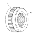
- FIG. 4 is a perspective view of the metal collar shown in FIG. 3. It is explanatory drawing of a connector fixing structure in case the outer diameter of the terminal connector of the electric wire end extended to the back surface of the power receiving side connector of one Embodiment is smaller than the electric wire penetration hole of a connector attachment part.
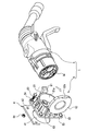
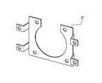
- FIG. 8 is a front view of the power receiving side connector of FIG. 7. It is a perspective view of the bracket used when attaching the conventional power receiving side connector to the back surface of a connector attaching part.
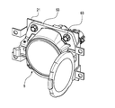
- FIG. 10 is a perspective view of a power receiving side connector to which the bracket shown in FIG. 9 is attached.
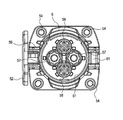
- FIG. 1 is a front view of an embodiment of the power receiving side connector of the connector fixing structure according to the present invention.
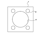
- 2 is a front view of the connector mounting portion of the vehicle body to which the power receiving side connector of FIG. 1 is mounted
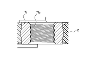
- FIG. 3 is a cross-sectional view taken along the line AA of FIG. 1, and FIG.
- the power receiving side connector 7 of this embodiment is an improvement of a part of the power receiving side connector 5 of FIG. 7, and the power feeding side connector 3 connected to the power feeding device can be fitted and connected so that it can be connected to the body of the electric vehicle. It is attached to the attachment part 4.
- the connector mounting portion 4 is formed around a wire insertion hole 41 for inserting an electric wire or the like extending from the back side of the power reception side connector 5, and the power reception side connector 41. And a screw insertion hole 42 for screwing 5.
- the power receiving side connector 7 includes an outer cylindrical wall portion 51 having a cylindrical structure smaller in diameter than the wire insertion hole 41, an opening / closing cap 52, a flange portion 53, a metal collar 71, and a temporary locking protrusion. .
- the configuration other than the metal collar 71 and the temporary locking protrusion may be the same as the corresponding configuration of the power receiving side connector 5 shown in FIG. Are given the same numbers and their explanation is omitted.
- reference numeral 74 denotes a power supply terminal held in the power supply terminal accommodating cylinder 57
- reference numeral 75 denotes a signal terminal held in the signal terminal accommodating cylinder 58.
- the metal collar 71 in the power receiving side connector 7 of the present embodiment is a cylindrical member through which a screw member can be inserted, and is fixed at a position on the flange portion 53 corresponding to the screw insertion hole 42 of the connector mounting portion 4.
- the metal collar 54 is fixed to the flange portion 53 by being press-fitted into a prepared hole penetratingly formed in the flange portion 53.
- this metal collar 71 is not a simple cylinder shape, but as shown in FIG.3 and FIG.4, it has the internal thread 71a in which the external thread which penetrated the screw insertion hole 42 can be screwed in the inner peripheral surface. .
- the temporary locking projection is provided on the outer periphery of the outer cylinder wall 51, and when the outer cylinder wall 51 is inserted into the electric wire insertion hole 41, the temporary engagement protrusion engages with the electric wire insertion hole 41, thereby receiving the power receiving side connector.
- 7 is a protruding member that temporarily fixes 7 to the connector mounting portion.
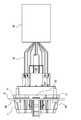
- FIG. 5 is an explanatory diagram of the connector fixing structure when the outer diameter of the terminal connector 82 at the end of the electric wire 81 extending to the back surface of the power receiving connector 7 of the embodiment is smaller than the electric wire insertion hole 41 of the connector mounting portion 4. is there.
- the electric wire 81 and the terminal connector 82 on the back surface of the power receiving side connector 7 are inserted into the electric wire insertion hole 41 of the connector mounting portion 4 from the vehicle body outer surface side, and the flange portion 53 is connected to the connector mounting portion 4 from the outer surface side of the vehicle body.
- the first male screw member 85 having a screw diameter smaller than the female screw 71 a of the metal collar 71 is inserted into the metal collar 71 and the screw insertion hole 42 of the connector mounting portion 4 from the outer surface side of the vehicle body.
- the power receiving connector 7 is fixed to the connector mounting portion 4 by screwing the nut 86 into the first male screw member 85 inserted through the screw insertion hole 42.
- FIG. 6 is an explanatory diagram of the connector fixing structure when the outer diameter of the terminal connector 82 at the end of the electric wire 81 extending to the back surface of the power receiving side connector 7 of the embodiment is larger than the electric wire insertion hole 41 of the connector mounting portion 4. is there.
- the terminal connector 82 cannot be inserted into the wire insertion hole 41 of the connector mounting portion 4. Therefore, the outer cylindrical wall portion 51 of the power receiving side connector 7 is inserted into the wire insertion hole 41 of the connector mounting portion 4 from the inner surface side of the vehicle body, and the flange portion 53 is overlapped with the connector mounting portion 4 from the inner surface side of the vehicle body.
- the outer cylinder wall 51 is inserted into the electric wire insertion hole 41, the temporary locking protrusion is engaged with the electric wire insertion hole 41, and the power receiving side connector 7 is temporarily fixed to the connector mounting portion 4.
- a second male screw member 88 having a male screw portion that is screwed into the female screw 71a portion is inserted into the screw insertion hole 42 of the connector mounting portion 4 from the outer surface side of the vehicle body, and screwed into the female screw 71a of the metal collar 71. By doing so, the power receiving side connector 7 is fixed to the connector mounting portion 4.
- the screw diameter is the metal collar 71 as shown in FIG.
- the power receiving side connector 7 can be easily fixed to the connector mounting portion 4 by a standard fastening operation using the first male screw member 85 having a smaller diameter than the female screw 71a and the nut 86.
- the second screw portion having a male screw portion that engages with the female screw 71 a portion of the metal collar 71 is provided. Only the male screw member 88 can fix the power-receiving-side connector 7 to the connector mounting portion 4, further facilitating the mounting operation.
- the outer cylindrical wall projecting to the front side of the power receiving side connector 7 when the flange portion 53 is attached to the connector mounting portion 4 from the inner surface side of the vehicle body.
- the portion 51 is inserted into the electric wire insertion hole 41 from the back side of the connector attachment portion 4, the temporary locking protrusion is engaged with the electric wire insertion hole 41, and the power receiving side connector 7 is temporarily fixed to the connector attachment portion 4. It becomes a state. For this reason, when the power receiving side connector 7 is fastened with screws, even if the power receiving side connector 7 is not supported from the back side of the connector mounting portion 4, the power receiving side connector 7 can be prevented from falling off. Fastening is further facilitated.
- each part of the power receiving side connector 7 fixed by the connector fixing structure of the present invention is not limited to the above-described embodiment, and appropriate modifications, improvements, and the like are possible.
- the present invention is not limited to the above-described embodiment, and can be appropriately modified and improved.
- the material, shape, dimension, numerical value, form, number, arrangement location, and the like of each component in the above-described embodiment are arbitrary and are not limited as long as the present invention can be achieved.
- the power receiving side connector of the present invention even when the power receiving side connector that is normally attached to the connector mounting portion of the vehicle body from the outer surface side of the vehicle body is attached to the connector mounting portion from the inner surface side of the vehicle body, a special part such as a bracket is attached.
- the attachment can be completed easily without using it, and the cost can be reduced and the workability can be improved.
Landscapes
- Engineering & Computer Science (AREA)
- Power Engineering (AREA)
- Transportation (AREA)
- Mechanical Engineering (AREA)
- Connector Housings Or Holding Contact Members (AREA)
- Details Of Connecting Devices For Male And Female Coupling (AREA)
Abstract
通常は車体の外面側から車体のコネクタ取付け部へ取り付けられる受電側コネクタを、車体の内面側からコネクタ取付け部に取り付ける場合でも、ブラケット等の特別な部品を用いることなく、簡単に取り付けを完了させることのできるコネクタ固定構造を提供することを目的とする。受電側コネクタ(7)のフランジ部(53)に固定される金属カラー(71)の内周面には雌ねじを形成しておき、フランジ部(53)が車体外面側からコネクタ取付け部(4)に装着されるときには、金属カラー(71)を挿通する第1の雄ねじ部材と該第1の雄ねじ部材に螺合するナットとでフランジ部(53)をコネクタ取付け部(4)に締結し、フランジ部(53)が車体内面側からコネクタ取付け部(4)に装着されるときには、金属カラー(71)に螺合する第2の雄ねじ部材(88)によりフランジ部(53)をコネクタ取付け部(4)に締結する。
Description
本発明は、電気自動車におけるバッテリの充電に使用される給電コネクタとして、車体に取り付けられる受電側コネクタのコネクタ固定構造に関する。
図7及び図8は、電気自動車におけるバッテリの充電に使用される給電コネクタの従来例を示したものである。
この給電コネクタ1は、下記特許文献1に開示されたもので、不図示の給電装置に接続された給電側コネクタ3と、該給電側コネクタ3が嵌合接続可能に電気自動車の車体のコネクタ取付け部4に取り付けられる受電側コネクタ5と、を備える。
コネクタ取付け部4は、受電側コネクタ5の背面から延出する電線等を挿通させるための電線挿通穴41と、該電線挿通穴41の周囲に形成されて受電側コネクタ5をねじ止めするためのねじ挿通穴42と、を備えている。
受電側コネクタ5は、電線挿通穴41よりも小径の筒状構造の外筒壁部51と、開閉キャップ52と、フランジ部53と、金属カラー54と、を備えている。
外筒壁部51は、給電側コネクタ3の筒状のハウジング前側筒部3aが内周に嵌合接続される筒状の部位である。この外筒壁部51の内側に、図8に示すように、電源用端子を収容保持する電源用端子収容筒部57と、信号用端子を収容保持する信号用端子収容筒部58とが備えられている。
開閉キャップ52は、外筒壁部51の開口51aを開閉可能に覆う略円形の蓋体である。この開閉キャップ52は、図7及び図8に示すように、外周の一側に係止部52aが設けられ、更に、係止部52aと対向する外周の他側は、ヒンジ機構59により外筒壁部51に回動可能に連結されている。
開閉キャップ52は、ヒンジ機構59による回動により、開口51aを開閉可能になっている。開閉キャップ52は、開口51aを閉じた状態では、別体に形成されて外筒壁部51の外周に固定されたキャップ係止片61が係止部52aに係合することで、開口51aを閉じた状態に固定される。
フランジ部53は、外筒壁部51の外周に鍔状に張り出し形成されている。このフランジ部53は、コネクタ取付け部4の電線挿通穴41の周縁部に重ねられる。
金属カラー54は、ねじ部材を挿通可能な筒状部材で、ねじ挿通穴42に対応するフランジ部53上の位置に固定されている。この金属カラー54は、フランジ部53に貫通形成された下孔に例えば圧入されることによって、フランジ部53に固定されている。なお、金属カラー54はフランジ部53に圧入して固定する以外に、フランジ部53の成形時に一体にインサート成形されてもよい。
以上に説明した受電側コネクタ5は、通常の場合、図7に示すように、フランジ部53が車体の外面側からコネクタ取付け部4に重ねられて、雄ねじ部材63とナット64により、コネクタ取付け部4に締結固定される。
フランジ部53をコネクタ取付け部4に重ねる際には、予め、受電側コネクタ5の背面から延出する電線等を、電線挿通穴41に挿通させる作業を行う。
ところで、受電側コネクタ5の背面から延出する電線等に接続される端末コネクタのサイズは、車載の給電部の規格等によって変化し、中には、電線挿通穴41を挿通できない大型のものもある。
このような大型の端末コネクタが接続されている電線は、電線挿通穴41に挿通できない。そのため、電線端に大型の端末コネクタが接続されている受電側コネクタ5の場合は、車体の内面側からコネクタ取付け部4に取り付ける。その際、従来では、図9及び図10に示すように、受電側コネクタ5にブラケット21を取り付け、このブラケット21を介して、受電側コネクタ5をコネクタ取付け部4に取り付けていた。
ところが、受電側コネクタ5を車体の内面側からコネクタ取付け部4に取り付ける場合に、図9及び図10に示したようにブラケット21を使用する従来のコネクタ固定構造では、別部品であるブラケット21を用意するために、コストアップを招くだけでなく、作業工程が増え、取り付け作業性が悪いという問題も生じた。
そこで、本発明の目的は、上記課題を解消することに係り、通常は車体の外面側から車体のコネクタ取付け部へ取り付けられる受電側コネクタを、車体の内面側からコネクタ取付け部に取り付ける場合でも、ブラケット等の特別な部品を用いることなく、簡単に取り付けを完了させることのできるコネクタ固定構造を提供することにある。
本発明の前述した目的は、下記の構成により達成される。
(1)給電側コネクタが嵌合接続可能な受電側コネクタを、電気自動車の車体のコネクタ取付け部にねじ部品により締結固定するコネクタ固定構造であって、
前記コネクタ取付け部は、前記受電側コネクタの背面から延出する電線等を挿通させるための電線挿通穴と、該電線挿通穴の周囲に形成されて前記受電側コネクタをねじ止めするためのねじ挿通穴と、を備え、
前記受電側コネクタは、前記電線挿通穴よりも小径の筒状構造に形成されて前記給電側コネクタの筒状のハウジング前側筒部が嵌合接続される外筒壁部と、前記外筒壁部の外周に張り出し形成されて前記電線挿通穴の周縁部に重ねられるフランジ部と、該フランジ部の前記ねじ挿通穴に対応する位置に固定されてねじ部材を挿通可能な筒状部材である金属カラーと、を備え、
前記金属カラーの内周面には、前記ねじ挿通穴を挿通させた雄ねじが螺合可能な雌ねじを備え、
前記フランジ部が前記車体の外面側から前記コネクタ取付け部に装着される場合には、ねじ径が前記雌ねじよりも小径の第1の雄ねじ部材を、前記車体の外面側から前記金属カラー及び前記ねじ挿通穴に挿通させ、前記ねじ挿通穴を挿通した前記第1の雄ねじ部材にナットを螺合させることで、受電側コネクタを前記コネクタ取付け部に固定し、
前記フランジ部が前記車体の内面側から前記コネクタ取付け部に装着される場合には、前記雌ねじ部に螺合する雄ねじ部を有した第2の雄ねじ部材を、前記車体の外面側から前記ねじ挿通穴に挿通し、前記金属カラーの雌ねじに螺合させることで、受電側コネクタを前記コネクタ取付け部に固定するコネクタ固定構造。
(1)給電側コネクタが嵌合接続可能な受電側コネクタを、電気自動車の車体のコネクタ取付け部にねじ部品により締結固定するコネクタ固定構造であって、
前記コネクタ取付け部は、前記受電側コネクタの背面から延出する電線等を挿通させるための電線挿通穴と、該電線挿通穴の周囲に形成されて前記受電側コネクタをねじ止めするためのねじ挿通穴と、を備え、
前記受電側コネクタは、前記電線挿通穴よりも小径の筒状構造に形成されて前記給電側コネクタの筒状のハウジング前側筒部が嵌合接続される外筒壁部と、前記外筒壁部の外周に張り出し形成されて前記電線挿通穴の周縁部に重ねられるフランジ部と、該フランジ部の前記ねじ挿通穴に対応する位置に固定されてねじ部材を挿通可能な筒状部材である金属カラーと、を備え、
前記金属カラーの内周面には、前記ねじ挿通穴を挿通させた雄ねじが螺合可能な雌ねじを備え、
前記フランジ部が前記車体の外面側から前記コネクタ取付け部に装着される場合には、ねじ径が前記雌ねじよりも小径の第1の雄ねじ部材を、前記車体の外面側から前記金属カラー及び前記ねじ挿通穴に挿通させ、前記ねじ挿通穴を挿通した前記第1の雄ねじ部材にナットを螺合させることで、受電側コネクタを前記コネクタ取付け部に固定し、
前記フランジ部が前記車体の内面側から前記コネクタ取付け部に装着される場合には、前記雌ねじ部に螺合する雄ねじ部を有した第2の雄ねじ部材を、前記車体の外面側から前記ねじ挿通穴に挿通し、前記金属カラーの雌ねじに螺合させることで、受電側コネクタを前記コネクタ取付け部に固定するコネクタ固定構造。
(2)前記外筒壁部には、前記電線挿通穴に挿通させたときに、前記電線挿通穴に係合して前記受電側コネクタを前記コネクタ取付け部に仮止めする仮係止突起を備えた上記(1)に記載のコネクタ固定構造。
上記(1)の構成によれば、フランジ部が車体の外面側からコネクタ取付け部に装着される場合には、ねじ径が金属カラーの雌ねじよりも小径の第1の雄ねじ部材とナットとを使った標準の締結作業により、簡単に、受電側コネクタをコネクタ取付け部に固定することができる。
一方、フランジ部が車体の内面側からコネクタ取付け部に装着される場合には、金属カラーの雌ねじ部に螺合する雄ねじ部を有した第2の雄ねじ部材のみで、受電側コネクタをコネクタ取付け部に固定することができ、更に取り付け作業が容易になる。
即ち、通常は車体の外面側から車体のコネクタ取付け部へ取り付けられる受電側コネクタを、車体の内面側からコネクタ取付け部に取り付ける場合でも、ブラケット等の特別な部品を用いることなく、簡単に取り付けを完了させることができ、コスト低減と作業性の向上を図ることができる。
上記(2)の構成によれば、フランジ部が車体の内面側からコネクタ取付け部に装着される場合に、受電側コネクタの前面側に突出している外筒壁部を、コネクタ取付け部の背面側から電線挿通穴に挿通させると、仮係止突起が電線挿通穴に係合して、受電側コネクタがコネクタ取付け部に仮止めされた状態になる。そのため、受電側コネクタをねじで締結する際に、コネクタ取付け部の背面側から受電側コネクタを支えていなくとも、受電側コネクタの脱落を防止することができ、受電側コネクタの締結作業が、更に容易になる。
以下、本発明に係る受電側コネクタ及びコネクタ固定構造の好適な実施形態について、図面を参照して詳細に説明する。
図1~図4は本発明に係るコネクタ固定構造の受電側コネクタの一実施形態を示したもので、図1は本発明に係るコネクタ固定構造の受電側コネクタの一実施形態の正面図、図2は図1の受電側コネクタが取り付けられる車体のコネクタ取付け部の正面図、図3は図1のA-A断面図、図4は図3に示した金属カラーの斜視図である。
この一実施形態の受電側コネクタ7は、図7の受電側コネクタ5の一部を改良したもので、給電装置に接続された給電側コネクタ3が嵌合接続可能に、電気自動車の車体のコネクタ取付け部4に取り付けられる。
コネクタ取付け部4は、図2に示すように、受電側コネクタ5の背面から延出する電線等を挿通させるための電線挿通穴41と、該電線挿通穴41の周囲に形成されて受電側コネクタ5をねじ止めするためのねじ挿通穴42と、を備えている。
受電側コネクタ7は、電線挿通穴41よりも小径の筒状構造の外筒壁部51と、開閉キャップ52と、フランジ部53と、金属カラー71と、仮係止突起と、を備えている。
本実施形態の受電側コネクタ7において、金属カラー71及び仮係止突起以外の構成は、図7に示した受電側コネクタ5の相応する構成と同様でよく、受電側コネクタ5と同様の構成については同番号を付して説明を省略する。
図1において、符号74は電源用端子収容筒部57内に保持された電源用端子を示し、符号75は信号用端子収容筒部58内に保持された信号用端子を示している。
本実施形態の受電側コネクタ7おける金属カラー71は、ねじ部材を挿通可能な筒状部材で、コネクタ取付け部4のねじ挿通穴42に対応するフランジ部53上の位置に固定されている。この金属カラー54は、フランジ部53に貫通形成された下孔に圧入されることによって、フランジ部53に固定されている。そして、この金属カラー71は、単純な筒状ではなく、図3及び図4に示すように、内周面に、ねじ挿通穴42を挿通させた雄ねじが螺合可能な雌ねじ71aを備えている。
前記仮係止突起は、外筒壁部51の外周に装備されていて、該外筒壁部51を電線挿通穴41に挿通させたときに電線挿通穴41に係合して、受電側コネクタ7をコネクタ取付け部に仮止めする突起部材である。
次に、以上に説明した受電側コネクタ7をコネクタ取付け部4に固定するコネクタ固定構造を図5及び図6を用いて説明する。
図5は、一実施形態の受電側コネクタ7の背面に延出した電線81端の端末コネクタ82の外径がコネクタ取付け部4の電線挿通穴41よりも小さい場合のコネクタ固定構造の説明図である。
この場合は、受電側コネクタ7の背面の電線81及び端末コネクタ82を、車体外面側からコネクタ取付け部4の電線挿通穴41に挿通させて、フランジ部53を車体の外面側からコネクタ取付け部4に重ね合わせる。次いで、ねじ径が金属カラー71の雌ねじ71aよりも小径の第1の雄ねじ部材85を、車体の外面側から前記金属カラー71及びコネクタ取付け部4のねじ挿通穴42に挿通させる。更に、ねじ挿通穴42を挿通した第1の雄ねじ部材85に、ナット86を螺合させることで、受電側コネクタ7をコネクタ取付け部4に固定する。
図6は、一実施形態の受電側コネクタ7の背面に延出した電線81端の端末コネクタ82の外径がコネクタ取付け部4の電線挿通穴41よりも大きい場合のコネクタ固定構造の説明図である。
この場合は、端末コネクタ82をコネクタ取付け部4の電線挿通穴41に挿通させることができない。そのため、受電側コネクタ7の外筒壁部51を車体の内面側からコネクタ取付け部4の電線挿通穴41に挿通させて、フランジ部53を車体の内面側からコネクタ取付け部4に重ね合わせる。外筒壁部51を電線挿通穴41に挿通させると、仮係止突起が電線挿通穴41に係合して、受電側コネクタ7がコネクタ取付け部4に仮止め状態となる。
次いで、雌ねじ71a部に螺合する雄ねじ部を有した第2の雄ねじ部材88を、車体の外面側からコネクタ取付け部4のねじ挿通穴42に挿通し、前記金属カラー71の雌ねじ71aに螺合させることで、受電側コネクタ7をコネクタ取付け部4に固定する。
以上に説明した一実施形態の受電側コネクタ7では、フランジ部53が車体の外面側からコネクタ取付け部4に装着される場合には、図5に示したように、ねじ径が金属カラー71の雌ねじ71aよりも小径の第1の雄ねじ部材85とナット86とを使った標準の締結作業により、簡単に、受電側コネクタ7をコネクタ取付け部4に固定することができる。
一方、フランジ部53が車体の内面側からコネクタ取付け部4に装着される場合には、図6に示したように、金属カラー71の雌ねじ71a部に螺合する雄ねじ部を有した第2の雄ねじ部材88のみで、受電側コネクタ7をコネクタ取付け部4に固定することができ、更に取り付け作業が容易になる。
即ち、通常は車体の外面側から車体のコネクタ取付け部4へ取り付けられる受電側コネクタ7を、車体の内面側からコネクタ取付け部4に取り付ける場合でも、ブラケット等の特別な部品を用いることなく、簡単に取り付けを完了させることができ、コスト低減と作業性の向上を図ることができる。
更に、以上に説明した一実施形態の受電側コネクタ7では、フランジ部53が車体の内面側からコネクタ取付け部4に装着される場合に、受電側コネクタ7の前面側に突出している外筒壁部51を、コネクタ取付け部4の背面側から電線挿通穴41に挿通させると、仮係止突起が電線挿通穴41に係合して、受電側コネクタ7がコネクタ取付け部4に仮止めされた状態になる。そのため、受電側コネクタ7をねじで締結する際に、コネクタ取付け部4の背面側から受電側コネクタ7を支えていなくとも、受電側コネクタ7の脱落を防止することができ、受電側コネクタ7の締結作業が、更に容易になる。
なお、本発明のコネクタ固定構造で固定する受電側コネクタ7の各部の具体的な構造は、前述した実施形態に限定されるものでなく、適宜な変形、改良等が可能である。
本発明は、上述した実施形態に限定されるものではなく、適宜、変形、改良等が自在である。その他、上述した実施形態における各構成要素の材質、形状、寸法、数値、形態、数、配置場所、等は本発明を達成できるものであれば任意であり、限定されない。
本発明を詳細にまた特定の実施態様を参照して説明したが、本発明の精神と範囲を逸脱することなく様々な変更や修正を加えることができることは当業者にとって明らかである。
本出願は、2010年12月20日出願の日本特許出願(特願2010-283314)に基づくものであり、その内容はここに参照として取り込まれる。
本発明による受電側コネクタによれば、通常は車体の外面側から車体のコネクタ取付け部へ取り付けられる受電側コネクタを、車体の内面側からコネクタ取付け部に取り付ける場合でも、ブラケット等の特別な部品を用いることなく、簡単に取り付けを完了させることができ、コスト低減と作業性の向上を図ることができる。
4 コネクタ取付け部
7 受電側コネクタ
41 電線挿通穴
42 ねじ挿通穴
51 外筒壁部
53 フランジ部
71 金属カラー
71a 雌ねじ
81 電線
82 端末コネクタ
85 第1の雄ねじ部材
86 ナット
88 第2の雄ねじ部材
7 受電側コネクタ
41 電線挿通穴
42 ねじ挿通穴
51 外筒壁部
53 フランジ部
71 金属カラー
71a 雌ねじ
81 電線
82 端末コネクタ
85 第1の雄ねじ部材
86 ナット
88 第2の雄ねじ部材
Claims (2)
- 給電側コネクタが嵌合接続可能な受電側コネクタを、電気自動車の車体のコネクタ取付け部にねじ部品により締結固定するコネクタ固定構造であって、
前記コネクタ取付け部は、前記受電側コネクタの背面から延出する電線等を挿通させるための電線挿通穴と、該電線挿通穴の周囲に形成されて前記受電側コネクタをねじ止めするためのねじ挿通穴と、を備え、
前記受電側コネクタは、前記電線挿通穴よりも小径の筒状構造に形成されて前記給電側コネクタの筒状のハウジング前側筒部が嵌合接続される外筒壁部と、前記外筒壁部の外周に張り出し形成されて前記電線挿通穴の周縁部に重ねられるフランジ部と、該フランジ部の前記ねじ挿通穴に対応する位置に固定されてねじ部材を挿通可能な筒状部材である金属カラーと、を備え、
前記金属カラーの内周面には、前記ねじ挿通穴を挿通させた雄ねじが螺合可能な雌ねじを備え、
前記フランジ部が前記車体の外面側から前記コネクタ取付け部に装着される場合には、ねじ径が前記雌ねじよりも小径の第1の雄ねじ部材を、前記車体の外面側から前記金属カラー及び前記ねじ挿通穴に挿通させ、前記ねじ挿通穴を挿通した前記第1の雄ねじ部材にナットを螺合させることで、受電側コネクタを前記コネクタ取付け部に固定し、
前記フランジ部が前記車体の内面側から前記コネクタ取付け部に装着される場合には、前記雌ねじ部に螺合する雄ねじ部を有した第2の雄ねじ部材を、前記車体の外面側から前記ねじ挿通穴に挿通し、前記金属カラーの雌ねじに螺合させることで、受電側コネクタを前記コネクタ取付け部に固定するコネクタ固定構造。 - 前記外筒壁部には、前記電線挿通穴に挿通させたときに、前記電線挿通穴に係合して前記受電側コネクタを前記コネクタ取付け部に仮止めする仮係止突起を備えた請求項1に記載のコネクタ固定構造。
Priority Applications (3)
| Application Number | Priority Date | Filing Date | Title |
|---|---|---|---|
| CN201180018375.5A CN102834985B (zh) | 2010-12-20 | 2011-12-08 | 连接器固定结构 |
| EP11850272.3A EP2658045B1 (en) | 2010-12-20 | 2011-12-08 | Connector fixing structure |
| US13/594,276 US8858256B2 (en) | 2010-12-20 | 2012-08-24 | Connector fixing structure |
Applications Claiming Priority (2)
| Application Number | Priority Date | Filing Date | Title |
|---|---|---|---|
| JP2010-283314 | 2010-12-20 | ||
| JP2010283314A JP5674123B2 (ja) | 2010-12-20 | 2010-12-20 | コネクタ固定構造 |
Related Child Applications (1)
| Application Number | Title | Priority Date | Filing Date |
|---|---|---|---|
| US13/594,276 Continuation US8858256B2 (en) | 2010-12-20 | 2012-08-24 | Connector fixing structure |
Publications (1)
| Publication Number | Publication Date |
|---|---|
| WO2012086430A1 true WO2012086430A1 (ja) | 2012-06-28 |
Family
ID=46313710
Family Applications (1)
| Application Number | Title | Priority Date | Filing Date |
|---|---|---|---|
| PCT/JP2011/078487 Ceased WO2012086430A1 (ja) | 2010-12-20 | 2011-12-08 | コネクタ固定構造 |
Country Status (5)
| Country | Link |
|---|---|
| US (1) | US8858256B2 (ja) |
| EP (1) | EP2658045B1 (ja) |
| JP (1) | JP5674123B2 (ja) |
| CN (1) | CN102834985B (ja) |
| WO (1) | WO2012086430A1 (ja) |
Cited By (2)
| Publication number | Priority date | Publication date | Assignee | Title |
|---|---|---|---|---|
| WO2014053221A1 (de) * | 2012-10-05 | 2014-04-10 | Audi Ag | Modulsystem für eine ladevorrichtung, ladevorrichtung sowie fahrzeug mit einer aus dem modulsystem erstellten ladevorrichtung |
| WO2014057958A1 (ja) * | 2012-10-12 | 2014-04-17 | 矢崎総業株式会社 | 充電インレット装置 |
Families Citing this family (9)
| Publication number | Priority date | Publication date | Assignee | Title |
|---|---|---|---|---|
| DE102012105139B4 (de) * | 2012-06-14 | 2025-02-13 | Dr. Ing. H.C. F. Porsche Aktiengesellschaft | Ladeanschlussvorrichtung für ein Kraftfahrzeug |
| DE102014003565A1 (de) * | 2013-03-19 | 2014-09-25 | Sumitomo Wiring Systems, Ltd. | Fahrzeugseitiger Verbinder und Verfahren zum Zusammenbauen desselben |
| WO2016144285A2 (en) * | 2013-12-13 | 2016-09-15 | Hewlett Packard Enterprise Development Lp | Connector with a retainer assembly |
| JP5952324B2 (ja) | 2014-02-21 | 2016-07-13 | トヨタ自動車株式会社 | 車両の充電部 |
| US9629272B1 (en) * | 2014-09-30 | 2017-04-18 | Apple Inc. | Electronic device with array of reworkable components |
| DE102018206837A1 (de) * | 2018-05-03 | 2019-11-07 | Bayerische Motoren Werke Aktiengesellschaft | Mittenverbinder für Fahrzeuge mit Hochvoltspeicher |
| JP7107859B2 (ja) * | 2019-01-25 | 2022-07-27 | トヨタ自動車株式会社 | 充電インレットの固定構造 |
| USD988991S1 (en) * | 2021-05-10 | 2023-06-13 | Ten Pao International Limited | Electric vehicle gun charger |
| JP7881645B2 (ja) * | 2024-05-17 | 2026-06-29 | ダイハツ工業株式会社 | 車両用外部充電ポート支持構造 |
Citations (2)
| Publication number | Priority date | Publication date | Assignee | Title |
|---|---|---|---|---|
| JP2752032B2 (ja) * | 1993-09-20 | 1998-05-18 | 矢崎総業株式会社 | 給電コネクタ |
| JP2006073207A (ja) * | 2004-08-31 | 2006-03-16 | Hirose Electric Co Ltd | 電気コネクタ |
Family Cites Families (9)
| Publication number | Priority date | Publication date | Assignee | Title |
|---|---|---|---|---|
| JP3262203B2 (ja) * | 1996-02-16 | 2002-03-04 | 矢崎総業株式会社 | 低挿抜力コネクタ |
| US6371768B1 (en) * | 1998-03-31 | 2002-04-16 | Daimlerchrysler Corporation | Universal charge port connector for electric vehicles |
| CA2474547C (en) * | 2004-07-16 | 2012-01-03 | Xantrex International | Electrical connector apparatus and cover therefor |
| US7121878B2 (en) * | 2005-03-07 | 2006-10-17 | Cheng Uei Precision Industry Co., Ltd. | Vibration resistant connector |
| EP1880448B1 (de) * | 2006-05-11 | 2013-10-23 | ABL SURSUM BAYERISCHE ELEKTROZUBEHÖR GmbH & Co. KG | Drehbare einspeisung |
| JP5392151B2 (ja) * | 2010-03-09 | 2014-01-22 | 住友電装株式会社 | 充電用コネクタ |
| JP5486398B2 (ja) * | 2010-05-12 | 2014-05-07 | 株式会社東海理化電機製作所 | 給電プラグロック装置 |
| JP5486397B2 (ja) * | 2010-05-12 | 2014-05-07 | 株式会社東海理化電機製作所 | 給電プラグロック装置 |
| US8075329B1 (en) * | 2010-06-08 | 2011-12-13 | Ford Global Technologies, Llc | Method and system for preventing disengagement between an electrical plug and a charge port on an electric vehicle |
-
2010
- 2010-12-20 JP JP2010283314A patent/JP5674123B2/ja active Active
-
2011
- 2011-12-08 CN CN201180018375.5A patent/CN102834985B/zh active Active
- 2011-12-08 EP EP11850272.3A patent/EP2658045B1/en active Active
- 2011-12-08 WO PCT/JP2011/078487 patent/WO2012086430A1/ja not_active Ceased
-
2012
- 2012-08-24 US US13/594,276 patent/US8858256B2/en active Active
Patent Citations (2)
| Publication number | Priority date | Publication date | Assignee | Title |
|---|---|---|---|---|
| JP2752032B2 (ja) * | 1993-09-20 | 1998-05-18 | 矢崎総業株式会社 | 給電コネクタ |
| JP2006073207A (ja) * | 2004-08-31 | 2006-03-16 | Hirose Electric Co Ltd | 電気コネクタ |
Cited By (4)
| Publication number | Priority date | Publication date | Assignee | Title |
|---|---|---|---|---|
| WO2014053221A1 (de) * | 2012-10-05 | 2014-04-10 | Audi Ag | Modulsystem für eine ladevorrichtung, ladevorrichtung sowie fahrzeug mit einer aus dem modulsystem erstellten ladevorrichtung |
| US10179517B2 (en) | 2012-10-05 | 2019-01-15 | Audi Ag | Module system for a charging apparatus, charging apparatus and vehicle including a charging apparatus constructed from the module system |
| WO2014057958A1 (ja) * | 2012-10-12 | 2014-04-17 | 矢崎総業株式会社 | 充電インレット装置 |
| US9463702B2 (en) | 2012-10-12 | 2016-10-11 | Yazaki Corporation | Charging inlet device |
Also Published As
| Publication number | Publication date |
|---|---|
| CN102834985A (zh) | 2012-12-19 |
| US8858256B2 (en) | 2014-10-14 |
| JP2012133925A (ja) | 2012-07-12 |
| CN102834985B (zh) | 2015-03-04 |
| EP2658045A4 (en) | 2014-05-28 |
| EP2658045A1 (en) | 2013-10-30 |
| JP5674123B2 (ja) | 2015-02-25 |
| US20120322302A1 (en) | 2012-12-20 |
| EP2658045B1 (en) | 2019-06-12 |
Similar Documents
| Publication | Publication Date | Title |
|---|---|---|
| JP5674123B2 (ja) | コネクタ固定構造 | |
| JP6434939B2 (ja) | コネクタ | |
| JP5772444B2 (ja) | クランプ | |
| JP5733573B2 (ja) | 機器用コネクタ | |
| KR20090012164A (ko) | 디바이스 커넥터와, 접속 방법, 그리고 이를 위한 장치 | |
| JP2018026286A (ja) | コネクタ | |
| US9231337B2 (en) | Connector and mounting method therefor | |
| JP6089105B2 (ja) | バッテリーセンサの位置決め具、これを備えるバッテリーセンサアッセンブリ、及びバッテリーセンサ | |
| US11121501B2 (en) | Connector having structure for separating connector from connection target | |
| JP6634420B2 (ja) | 機器直付用シールドコネクタ | |
| US20120178291A1 (en) | Device-connecting connector | |
| JP5532333B2 (ja) | 壁に取り付け可能な機器 | |
| JP5973261B2 (ja) | カバー | |
| US8038194B2 (en) | Mounting structure of deck side trim | |
| JP4648889B2 (ja) | 車両用ミラー・方向指示器装置 | |
| CN105684228B (zh) | 连接器 | |
| CN208484747U (zh) | 电动车辆及其充电口结构 | |
| MX2021014152A (es) | Estructura de equipo electrico de vehiculo. | |
| JP2010179680A (ja) | 車両用スピーカ装置 | |
| WO2014175116A1 (ja) | コネクタ | |
| JP2021066195A (ja) | スロットルパイプの取り付け構造 | |
| JP2013172163A (ja) | ケーシングのビス止め構造及びこれを具えた電子機器 | |
| JP2020127262A (ja) | 電気接続箱 | |
| JP2016095977A (ja) | コネクタ | |
| US20210276495A1 (en) | Externally mounted component of a motor vehicle |
Legal Events
| Date | Code | Title | Description |
|---|---|---|---|
| WWE | Wipo information: entry into national phase |
Ref document number: 201180018375.5 Country of ref document: CN |
|
| 121 | Ep: the epo has been informed by wipo that ep was designated in this application |
Ref document number: 11850272 Country of ref document: EP Kind code of ref document: A1 |
|
| WWE | Wipo information: entry into national phase |
Ref document number: 2011850272 Country of ref document: EP |
|
| NENP | Non-entry into the national phase |
Ref country code: DE |