WO2012086475A1 - スリット詰まり抑制装置 - Google Patents
スリット詰まり抑制装置 Download PDFInfo
- Publication number
- WO2012086475A1 WO2012086475A1 PCT/JP2011/078847 JP2011078847W WO2012086475A1 WO 2012086475 A1 WO2012086475 A1 WO 2012086475A1 JP 2011078847 W JP2011078847 W JP 2011078847W WO 2012086475 A1 WO2012086475 A1 WO 2012086475A1
- Authority
- WO
- WIPO (PCT)
- Prior art keywords
- slit
- opening
- shaft
- cleaning member
- rotation
- Prior art date
- Legal status (The legal status is an assumption and is not a legal conclusion. Google has not performed a legal analysis and makes no representation as to the accuracy of the status listed.)
- Ceased
Links
Images


Classifications
-
- B—PERFORMING OPERATIONS; TRANSPORTING
- B03—SEPARATION OF SOLID MATERIALS USING LIQUIDS OR USING PNEUMATIC TABLES OR JIGS; MAGNETIC OR ELECTROSTATIC SEPARATION OF SOLID MATERIALS FROM SOLID MATERIALS OR FLUIDS; SEPARATION BY HIGH-VOLTAGE ELECTRIC FIELDS
- B03C—MAGNETIC OR ELECTROSTATIC SEPARATION OF SOLID MATERIALS FROM SOLID MATERIALS OR FLUIDS; SEPARATION BY HIGH-VOLTAGE ELECTRIC FIELDS
- B03C1/00—Magnetic separation
- B03C1/02—Magnetic separation acting directly on the substance being separated
- B03C1/10—Magnetic separation acting directly on the substance being separated with cylindrical material carriers
- B03C1/14—Magnetic separation acting directly on the substance being separated with cylindrical material carriers with non-movable magnets
-
- B—PERFORMING OPERATIONS; TRANSPORTING
- B03—SEPARATION OF SOLID MATERIALS USING LIQUIDS OR USING PNEUMATIC TABLES OR JIGS; MAGNETIC OR ELECTROSTATIC SEPARATION OF SOLID MATERIALS FROM SOLID MATERIALS OR FLUIDS; SEPARATION BY HIGH-VOLTAGE ELECTRIC FIELDS
- B03C—MAGNETIC OR ELECTROSTATIC SEPARATION OF SOLID MATERIALS FROM SOLID MATERIALS OR FLUIDS; SEPARATION BY HIGH-VOLTAGE ELECTRIC FIELDS
- B03C1/00—Magnetic separation
- B03C1/02—Magnetic separation acting directly on the substance being separated
- B03C1/30—Combinations with other devices, not otherwise provided for
-
- B—PERFORMING OPERATIONS; TRANSPORTING
- B03—SEPARATION OF SOLID MATERIALS USING LIQUIDS OR USING PNEUMATIC TABLES OR JIGS; MAGNETIC OR ELECTROSTATIC SEPARATION OF SOLID MATERIALS FROM SOLID MATERIALS OR FLUIDS; SEPARATION BY HIGH-VOLTAGE ELECTRIC FIELDS
- B03C—MAGNETIC OR ELECTROSTATIC SEPARATION OF SOLID MATERIALS FROM SOLID MATERIALS OR FLUIDS; SEPARATION BY HIGH-VOLTAGE ELECTRIC FIELDS
- B03C1/00—Magnetic separation
- B03C1/02—Magnetic separation acting directly on the substance being separated
- B03C1/23—Magnetic separation acting directly on the substance being separated with material carried by oscillating fields; with material carried by travelling fields, e.g. generated by stationary magnetic coils; Eddy-current separators, e.g. sliding ramp
- B03C1/24—Magnetic separation acting directly on the substance being separated with material carried by oscillating fields; with material carried by travelling fields, e.g. generated by stationary magnetic coils; Eddy-current separators, e.g. sliding ramp with material carried by travelling fields
- B03C1/247—Magnetic separation acting directly on the substance being separated with material carried by oscillating fields; with material carried by travelling fields, e.g. generated by stationary magnetic coils; Eddy-current separators, e.g. sliding ramp with material carried by travelling fields obtained by a rotating magnetic drum
-
- B—PERFORMING OPERATIONS; TRANSPORTING
- B03—SEPARATION OF SOLID MATERIALS USING LIQUIDS OR USING PNEUMATIC TABLES OR JIGS; MAGNETIC OR ELECTROSTATIC SEPARATION OF SOLID MATERIALS FROM SOLID MATERIALS OR FLUIDS; SEPARATION BY HIGH-VOLTAGE ELECTRIC FIELDS
- B03C—MAGNETIC OR ELECTROSTATIC SEPARATION OF SOLID MATERIALS FROM SOLID MATERIALS OR FLUIDS; SEPARATION BY HIGH-VOLTAGE ELECTRIC FIELDS
- B03C1/00—Magnetic separation
- B03C1/02—Magnetic separation acting directly on the substance being separated
- B03C1/28—Magnetic plugs and dipsticks
-
- B—PERFORMING OPERATIONS; TRANSPORTING
- B03—SEPARATION OF SOLID MATERIALS USING LIQUIDS OR USING PNEUMATIC TABLES OR JIGS; MAGNETIC OR ELECTROSTATIC SEPARATION OF SOLID MATERIALS FROM SOLID MATERIALS OR FLUIDS; SEPARATION BY HIGH-VOLTAGE ELECTRIC FIELDS
- B03C—MAGNETIC OR ELECTROSTATIC SEPARATION OF SOLID MATERIALS FROM SOLID MATERIALS OR FLUIDS; SEPARATION BY HIGH-VOLTAGE ELECTRIC FIELDS
- B03C1/00—Magnetic separation
- B03C1/02—Magnetic separation acting directly on the substance being separated
- B03C1/28—Magnetic plugs and dipsticks
- B03C1/284—Magnetic plugs and dipsticks with associated cleaning means, e.g. retractable non-magnetic sleeve
-
- B—PERFORMING OPERATIONS; TRANSPORTING
- B03—SEPARATION OF SOLID MATERIALS USING LIQUIDS OR USING PNEUMATIC TABLES OR JIGS; MAGNETIC OR ELECTROSTATIC SEPARATION OF SOLID MATERIALS FROM SOLID MATERIALS OR FLUIDS; SEPARATION BY HIGH-VOLTAGE ELECTRIC FIELDS
- B03C—MAGNETIC OR ELECTROSTATIC SEPARATION OF SOLID MATERIALS FROM SOLID MATERIALS OR FLUIDS; SEPARATION BY HIGH-VOLTAGE ELECTRIC FIELDS
- B03C1/00—Magnetic separation
- B03C1/02—Magnetic separation acting directly on the substance being separated
- B03C1/28—Magnetic plugs and dipsticks
- B03C1/286—Magnetic plugs and dipsticks disposed at the inner circumference of a recipient, e.g. magnetic drain bolt
-
- B—PERFORMING OPERATIONS; TRANSPORTING
- B23—MACHINE TOOLS; METAL-WORKING NOT OTHERWISE PROVIDED FOR
- B23Q—DETAILS, COMPONENTS, OR ACCESSORIES FOR MACHINE TOOLS, e.g. ARRANGEMENTS FOR COPYING OR CONTROLLING; MACHINE TOOLS IN GENERAL CHARACTERISED BY THE CONSTRUCTION OF PARTICULAR DETAILS OR COMPONENTS; COMBINATIONS OR ASSOCIATIONS OF METAL-WORKING MACHINES, NOT DIRECTED TO A PARTICULAR RESULT
- B23Q11/00—Accessories fitted to machine tools for keeping tools or parts of the machine in good working condition or for cooling work; Safety devices specially combined with or arranged in, or specially adapted for use in connection with, machine tools
Definitions
- the present invention relates to a slit clogging suppression device for cleaning a slit of a rotary drum type magnetic separation device that separates and collects sludge contained in a used coolant liquid.
- Patent Document 1 discloses a conventional rotary drum type magnetic separation device.
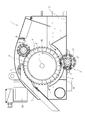
- FIG. 1 is a cross-sectional view taken along a plane orthogonal to the rotation axis of a rotary drum, showing the configuration of a conventional rotary drum type magnetic separation device.
- a conventional rotary drum type magnetic separation apparatus 1 is provided with a liquid reservoir 10 for storing a coolant liquid in a box-shaped main body.
- the rotary drum 3 is pivotally supported in a substantially horizontal direction in the vicinity of the central portion of the main body so as to divide the liquid reservoir 10 into two.
- the rotating drum 3 has a cylindrical body made of a non-magnetic material such as stainless steel, and an inner cylinder 5 in which a plurality of magnets 4, 4,. It is fixed coaxially inside. The polarities of the plurality of magnets 4, 4,. Is arranged to generate.
- Patent Document 1 a plurality of inner cylinders 5 corresponding to a portion corresponding to approximately three-fourths of the outer peripheral surface of the rotating drum 3, from the portion immersed in the liquid reservoir 10 of the rotating drum 3 to the top, are provided. Of magnets 4, 4,... Are arranged. The magnet 4 is not disposed on the inner cylinder 5 in the portion corresponding to the remaining substantially one-fourth, and the magnetic force does not act.
- the liquid component contained in the sludge is squeezed out, and only cutting chips, chips, etc. are separated at a position where the magnetic force does not reach. Is done.
- a slit-shaped opening 8 is provided at the bottom of the magnetic field flow path 16 along the outer peripheral surface of the rotating drum 3 in order to suppress the accumulation amount of abrasive grains that could not be collected. By providing the opening 8, it is possible to increase the recovery rate of cutting scraps and chips while maintaining the abrasive recovery rate.
- Patent Document 1 abrasive grains are collected from the slit-shaped opening 8, but there is a possibility that nonmagnetic particles that are larger than the opening width are clogged by the opening 8 and the abrasive recovery rate may be greatly reduced. There was a point. Moreover, the work of regularly cleaning is also complicated, and there is a possibility that work efficiency may be lowered as a whole process.
- This invention is made
- a slit clogging suppression device includes a rotary drum having a plurality of magnets arranged therein, and is used in a rotary drum type magnetic separation device that separates unnecessary substances in a treated coolant liquid.
- a slit-shaped opening is provided below the rotating drum, and a slit cleaning member partially inserted into the opening is configured to move along the longitudinal direction of the opening. It is characterized by.
- a rotating drum type magnetic separation device that includes a rotating drum on which a plurality of magnets are arranged and separates unnecessary substances in the treated coolant liquid is used.
- a slit cleaning member provided with a slit-like opening below the rotating drum and partially inserted into the opening moves along the longitudinal direction of the opening. When the slit cleaning member moves along the longitudinal direction of the slit-shaped opening, it is possible to prevent the opening from being clogged with abrasive grains.
- the moving mechanism for moving the slit cleaning member is disposed substantially parallel to the opening and at a position away from directly below the opening. It is characterized by being.
- the moving mechanism for moving the slit cleaning member is disposed substantially parallel to the opening and away from the position immediately below the opening. Thereby, the movement of a slit cleaning member is not controlled by the abrasive grain discharged from an opening part.
- the slit clogging suppressing device is characterized in that, in the second invention, a plate-like member is attached substantially in parallel to the opening between the moving mechanism and the opening.
- the third aspect of the invention by attaching a plate-like member between the moving mechanism and the opening, substantially parallel to the opening, the possibility that the abrasive particles discharged from the opening are guided to the moving mechanism is reduced. It becomes possible to separate and collect abrasive grains stably.
- a slit clogging suppressing device is any one of the first to third aspects, wherein the cylindrical shaft having a rotatable groove portion below the opening portion and the groove portion.
- a cylindrical groove cam mechanism configured with the slit cleaning member to be engaged is provided as the moving mechanism.
- a cylindrical groove cam mechanism including a cylindrical shaft having a rotatable groove portion and a slit cleaning member engaged with the groove portion is provided as a moving mechanism below the opening portion.
- the slit cleaning member connected to the cam mechanism moves along the longitudinal direction of the slit-shaped opening, so that the slit cleaning member can always move along the longitudinal direction of the opening. It is possible to suppress clogging of the opening due to the grains.
- the slit clogging suppression device is the fourth aspect, wherein the cylindrical groove cam mechanism is formed such that the groove portion is formed in a female screw shape and is formed in a male screw shape of the slit cleaning member.
- the protrusions are engaged and connected, and the slit cleaning member moves along the longitudinal direction of the opening according to the rotation of the shaft.
- the cylindrical groove cam mechanism has a groove portion formed in a female screw shape, and is connected by engaging a projection portion formed in a male screw shape of the slit cleaning member.
- the slit clogging suppression device is the fourth or fifth aspect of the present invention, wherein the cylindrical groove cam mechanism is such that the groove is formed in a cross screw shape, and the protrusion of the slit cleaning member is used as the groove.
- the slit cleaning member is moved along the longitudinal direction of the opening in accordance with the rotation of the shaft.
- the cylindrical groove cam mechanism has a groove portion formed in a cross screw shape, and is connected by engaging a protruding portion of the slit cleaning member with the groove portion.
- the slit clogging suppression device according to the sixth aspect, further comprising a rotation transmission mechanism that transmits the rotation of the rotation shaft to the shaft at least one end of the rotation shaft of the rotation drum.
- the cylindrical groove cam mechanism is operated.
- At least one end of the rotating shaft of the rotating drum is provided with a rotation transmission mechanism that transmits the rotation of the rotating shaft to the shaft, and the cylindrical groove cam mechanism is operated by the rotation of the rotating drum.
- the rotation transmission mechanism includes a chain unit mounted on at least one end of the shaft, and the chain is mounted on at least one end of the rotating shaft of the rotating drum. It is characterized by having a continuous protrusion that can mesh with the unit.
- a chain unit is attached to at least one end of the shaft, and at least one end of the rotating shaft of the rotating drum is provided with a continuous protrusion that can mesh with the chain unit.
- a slit clogging suppressing device is the first aspect of the invention, wherein two cylindrical members that can be rotated are provided below the opening, and an annular member that is wound around the cylindrical members. As a moving mechanism, and the slit cleaning member is fixed to a part of the annular member.
- two cylindrical members that can rotate and an annular member wound around the cylindrical member are provided as a moving mechanism below the opening, and a slit is formed in a part of the annular member.
- the cleaning member is fixed.
- the slit cleaning member provided with a slit-like opening below the rotating drum and partially inserted into the opening moves along the longitudinal direction of the opening.
- the slit cleaning member moves along the longitudinal direction of the slit-shaped opening, it is possible to prevent the opening from being clogged with abrasive grains.
- FIG. 2 is a cross-sectional view taken along a plane orthogonal to the rotation axis of the rotary drum, showing the configuration of the rotary drum type magnetic separation device using the slit clogging suppression device according to Embodiment 1 of the present invention.
- the rotary drum type magnetic separation device 1 using the slit clogging suppression device according to the first embodiment is provided with a liquid reservoir 10 that stores a coolant liquid in a box-shaped main body.
- the rotary drum 3 is pivotally supported by a rotary shaft 31 in the vicinity of the central portion of the main body so as to divide the liquid reservoir 10 in half so that the rotary drum 3 can rotate in a substantially horizontal direction.
- the rotating drum 3 is a cylindrical body made of a non-magnetic material such as stainless steel, and an inner cylinder 5 having a plurality of magnets 4, 4,.
- the shaft 31 is fixed coaxially.
- the plurality of magnets 4, 4,... Arranged in the inner cylinder 5 are arranged by appropriately adjusting the magnetic poles so that a required magnetic force acts on the outer peripheral surface of the rotating drum 3.
- a neodymium magnet is used as the magnet 4, and a pair of N and S is arranged in the order of N, S, N, and S from one end on the squeeze roller 6 side.
- the range in which the magnetic force is applied to the rotating drum 3 varies depending on the outer diameter of the drum, the position of the scraper 7, and the like.
- the magnets 4, 4,... are placed on the inner cylinder 5 so that the adsorption force extends in a range of about 3/4 of the outer peripheral surface from the portion immersed in the liquid reservoir 10 of the rotating drum 3 to the top.
- No magnet is arranged on the inner cylinder 5 in the remaining approximately 1/4 range of the outer peripheral surface. Sludge containing cutting waste, chips and the like adsorbed on the outer peripheral surface of the rotating drum 3 in the magnetic field flow path 16 where the magnetic force acts is conveyed to the top of the rotating drum 3 by the rotation of the rotating drum 3.
- a squeezing roller 6 is disposed near the top of the rotating drum 3 and is in contact with the outer peripheral surface of the rotating drum 3 with a predetermined pressure.
- the squeezing roller 6 squeezes out the liquid contained in the sludge that is adsorbed to the outer peripheral surface of the rotary drum 3 and conveyed.
- the scraps, chips, etc., from which the liquid has been squeezed out are released from the attractive force of the magnets 4, 4,... It is scraped and collected by the scraper 7.
- the coolant liquid is initially stored in the liquid reservoir 10 and then passes through the magnetic field channel 16 formed by the rotating drum 3 and the casing bottom plate 9 disposed along the rotating drum 3. By passing through the magnetic field flow path 16, cutting waste, chips and the like mixed in the liquid are separated and recovered.
- an opening 8 is provided at a position of the magnetic field channel 16 facing the outer cylinder of the rotating drum 3.
- the opening 8 has a parallel slit shape perpendicular to the rotation direction of the rotation shaft 31 of the rotary drum 3.
- the opening 8 is made by initially bending a plate-shaped stainless steel (SUS304) with a laser or a turret punch so as to form a constant opening width in the thickness direction, and then bending it into an arc shape. .
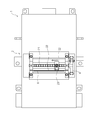
- FIG. 3 is a plan view showing the configuration of the slit clogging suppressing device 2 according to Embodiment 1 of the present invention.
- FIG. 3 is a view of the bottom surface of the rotary drum type magnetic separation device 1 as viewed from the bottom surface side.
- a cylindrical groove cam mechanism including a cylindrical shaft 21 having a rotatable groove portion and a slit cleaning member 22 engaged with the groove portion below the opening portion 8, It is provided as a moving mechanism for moving the slit cleaning member 22.
- the cylindrical shaft 21 is provided substantially parallel to the longitudinal direction of the slit-shaped opening 8, and is disposed at a position shifted from directly below the opening 8 in the rotation direction of the rotary drum 3. It is. By shifting from directly below the opening 8, the movement of the slit cleaning member 22 is not restricted by the abrasive particles discharged from the opening 8.
- the slit cleaning member 22 moves along the longitudinal direction of the opening 8 on the shaft 21.
- the slit cleaning pin 23 provided at the tip of the slit cleaning member 22 reciprocates in the slit-like opening 8 along the longitudinal direction of the opening 8. Abrasive grains deposited in the vicinity can be effectively eliminated.
- a plate-like member 28 is attached between the shaft 21 and the slit-like opening 8 so as to be substantially parallel to the longitudinal direction of the opening 8. This is because the possibility that the abrasive grains discharged from the opening 8 are guided to the cylindrical groove cam mechanism is reduced, and the abrasive grains can be stably separated and recovered.
- the cylindrical groove cam mechanism has a groove portion of the cylindrical shaft 21 formed in a cross screw shape, and the projection portion of the slit cleaning member 22 is engaged with the groove portion and connected.
- the shaft 21 rotates, the slit cleaning member 22 moves in the slit-shaped opening 8 along the longitudinal direction of the opening 8 according to the rotation of the shaft 21.
- the slit cleaning member 22 moves along the longitudinal direction of the opening 8 according to the rotation of the shaft 21, it is possible to suppress clogging of the abrasive grains in the opening 8 and to separate the abrasive grains by free maintenance. It becomes possible to collect.
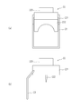
- FIG. 4 is a front view and a side view showing the configuration of the slit cleaning member 22 of the slit clogging suppression device 2 according to Embodiment 1 of the present invention.
- FIG. 4 (a) is a front view showing the configuration of the slit cleaning member 22 of the slit clogging suppression device 2 according to Embodiment 1 of the present invention
- FIG. 4 (b) shows the configuration of Embodiment 1 of the present invention.
- It is a side view which shows the structure of the slit cleaning member 22 of the slit clogging suppression apparatus 2 which concerns.
- the slit cleaning member 22 includes a main body portion 221 that reciprocates along the longitudinal direction of the opening 8 on the cylindrical shaft 21, a protrusion 222 that engages with a groove portion of the shaft 21, and a fixing portion 223. It is connected so that it can reciprocate on 21.
- the slit cleaning pin 23 has a shape bent toward the outside of the main body 221 so that the slit cleaning pin 23 can be inserted into the opening 8 at a position away from the protrusion 222 that engages with the groove of the shaft 21. Thereby, possibility that the reciprocating movement in the opening part 8 of the slit cleaning pin 23 will be prevented by the abrasive grain discharged and falling from the opening part 8 can be made low.
- the shape of the slit cleaning pin 23 is not limited to the shape shown in FIG. 4, and the slit cleaning pin 23 is formed in the slit-shaped opening without disposing the shaft 21 at a position shifted from directly below the opening 8. Any shape can be used as long as it can be inserted into the shape 8.
- the power source for rotating the shaft 21 is shared with the power source for rotating the rotary drum 3. That is, at least one end of the rotating shaft 31 of the rotating drum 3 is provided with a rotation transmission mechanism that transmits the rotation of the rotating shaft 31 to the shaft 21. In this way, there is no need to provide a separate power source for cleaning the slit-shaped opening 8 and suppressing clogging of the abrasive grains, and the shaft 21 is rotated by the power source for rotating the rotary drum 3. It is possible to suppress clogging of the abrasive grains in the opening 8 by moving the slit cleaning member 22.
- a chain unit 41 is mounted on at least one end of the shaft 21, and a continuous protrusion 42 that can mesh with the chain unit 41 on at least one end of the rotation shaft 31 of the rotary drum 3. It has. Thereby, it is not necessary to provide a separate power source for cleaning the slit-like opening 8 and suppressing clogging of the abrasive grains, and the shaft 21 is driven by the power source for rotating the rotary drum 3 via a simple mechanism. It is possible to suppress clogging of abrasive grains in the opening 8 by rotating the slit cleaning member 22.
- the chain unit 41 meshing with the plurality of continuous protrusions 42, 42,... Rotates clockwise.
- the shaft 21 is also rotated clockwise, and the protrusion 222 of the slit cleaning member 22 is engaged with a groove formed in a cross screw shape so that the shaft 21 is connected.
- the slit cleaning member 22 moves linearly along one of the longitudinal directions of the opening 8.
- the groove is formed in a cross screw shape, so that the protrusion 222 of the slit cleaning member 22 can be changed without changing the rotation direction of the shaft 21. It moves linearly in the opposite direction from one end of the opening 8 that has reached. Therefore, the slit cleaning member 22 moves along the longitudinal direction of the slit-shaped opening 8 while continuously rotating the rotary drum 3, so that the opening 8 can be prevented from being clogged with abrasive grains.
- the abrasive grains can be separated and recovered by free maintenance.
- the slit cleaning member 22 connected to the cylindrical groove cam mechanism moves along the longitudinal direction of the slit-shaped opening 8 to thereby perform slit cleaning.
- the slit cleaning pin 23 of the member 22 can always move in the opening 8 along the longitudinal direction of the opening 8, and it is possible to suppress the opening 8 from being clogged with abrasive grains.
- the cylindrical groove cam mechanism can be operated by a power source that rotates the rotary drum 3 through a simple mechanism such as the chain unit 41, the slit-shaped opening 8 is cleaned and the abrasive grains are clogged. There is no need to provide a separate power source in order to suppress this.
- Embodiment 2 Since the configuration of the rotary drum type magnetic separation device 1 itself using the slit clogging suppression device according to Embodiment 2 of the present invention is the same as the conventional configuration (see FIG. 1), the same reference numerals are attached. Therefore, detailed description is omitted.
- the second embodiment is different from the first embodiment in that the slit-shaped opening 8 is manually cleaned to prevent clogging of abrasive grains.
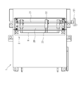
- FIG. 5 is a plan view showing the configuration of the slit clogging suppressing device 2 according to Embodiment 2 of the present invention.
- FIG. 5 is a view of the bottom surface of the rotary drum type magnetic separation device 1 as viewed from the bottom surface side.
- a cylindrical groove cam mechanism having a cylindrical shaft 21 having a rotatable groove portion and a slit cleaning member 22 engaged with the groove portion is provided below the opening 8. is doing.
- the cylindrical shaft 21 is provided substantially parallel to the longitudinal direction of the slit-shaped opening 8, and is disposed at a position shifted from directly below the opening 8 in the rotation direction of the rotary drum 3. It is. By shifting from directly below the opening 8, the movement of the slit cleaning member 22 is not restricted by the abrasive particles discharged from the opening 8.
- the cylindrical shaft 21 has a female screw-like groove, and the slit cleaning member 22 has a male screw-like protrusion 222.
- the groove portion of the shaft 21 and the projection portion 222 of the slit cleaning member 22 are engaged and connected, and the slit cleaning member 22 moves along the longitudinal direction of the slit-shaped opening 8 according to the rotation of the shaft 21.
- An operation handle 51 capable of manually rotating the shaft 21 is provided at one end of the shaft 21.
- the shaft 21 also rotates clockwise.
- the slit cleaning member 22 is operated along the longitudinal direction of the opening 8 in accordance with the rotation of the shaft 21 that is connected by engaging the protrusion 222 of the slit cleaning member 22 with the groove formed in a cross screw shape. It moves linearly in the direction approaching the handle 51.
- the shaft 21 also rotates counterclockwise. Due to the rotation of the shaft 21, the slit cleaning member 22 moves linearly in the direction away from the operation handle 51 along the longitudinal direction of the opening 8 through the protrusion 222 engaged with the groove portion of the shaft 21. .
- the slit cleaning pin 23 provided at the tip of the slit cleaning member 22 reciprocates in the slit-shaped opening 8 along the longitudinal direction of the opening 8. Abrasive grains deposited near the portion 8 can be effectively eliminated.
- a plate-like member 28 is attached between the shaft 21 and the slit-like opening 8 so as to be substantially parallel to the longitudinal direction of the opening 8. This is because the possibility that the abrasive grains discharged from the opening 8 are guided to the cylindrical groove cam mechanism is reduced, and the abrasive grains can be stably separated and recovered.
- the cylindrical groove cam mechanism is such that the groove portion is formed in a female screw shape, and the projection portion 222 formed in the male screw shape of the slit cleaning member 22 is engaged. Are connected.
- the cylindrical groove cam mechanism can be manually operated, a power source is provided separately from the power source for rotating the rotary drum 3 in order to clean the slit-like opening 8 and prevent clogging of abrasive grains. There is no need to provide it.
- Embodiment 3 Since the configuration of the rotary drum type magnetic separation device 1 itself using the slit clogging suppression device according to Embodiment 3 of the present invention is the same as the conventional configuration (see FIG. 1), the same reference numerals are attached. Therefore, detailed description is omitted.
- the third embodiment is different from the first and second embodiments in that the moving mechanism that moves the slit cleaning member 22 is an annular member that is wound around two cylindrical members.
- FIG. 6 is a plan view showing the configuration of the slit clogging suppressing device 2 according to Embodiment 3 of the present invention.
- FIG. 6 is a view of the bottom surface of the rotary drum type magnetic separation device 1 as viewed from the bottom surface side.
- the opening portion 8 As shown in FIG. 6, below the opening portion 8, it is composed of two columnar members 61, 61 that can rotate, and an annular member 62 that hangs around the columnar members 61, 61.
- a moving mechanism is provided.
- two sprockets are used as the cylindrical members 61 and 61 and a chain belt is used as the annular member 62, and the slit cleaning member 22 is fixed to a part of the chain belt.
- the present invention is not limited to the combination of the sprocket and the chain belt, and any combination is possible as long as the annular member 62 can move in accordance with the rotation of the two cylindrical members 61, 61, such as a combination of a roller and a belt. good.
- the annular member 62 moves in either direction of the arrow in FIG.
- the annular member 62 is rotated in the direction of the arrow A
- the annular member 62 is rotated by the arrow.
- Each moves in the B direction.
- the slit cleaning member 22 fixed to the annular member 62 also moves along the longitudinal direction of the slit-shaped opening 8. Since a part of the slit cleaning member 22 is inserted into the opening 8, the abrasive grains deposited in the vicinity of the opening 8 can be effectively eliminated.
- the two cylindrical members 61 and 61 that can rotate and the annular member that is wound around the cylindrical members 61 and 61 are provided below the opening 8. 62, and the slit cleaning member 22 is fixed to the annular member 62.
- a part of the slit cleaning member 22 that is fixed is inserted into the slit-shaped opening 8 by moving the annular member 62 that is wound around by rotating the two cylindrical members 61, 61. 8 along the longitudinal direction.
- a chain unit 41 is attached to at least one end of the shaft 21, and a continuous protrusion 42 that can mesh with the chain unit 41 at least one end of the rotation shaft 31 of the rotary drum 3.
- the chain unit 41 may be provided at both ends of the shaft 21, but the mechanism is not particularly limited as long as it is a mechanism capable of transmitting rotation, such as a gear mechanism and a belt mechanism, instead of the chain unit. Is not to be done.
Landscapes
- Engineering & Computer Science (AREA)
- Mechanical Engineering (AREA)
- Auxiliary Devices For Machine Tools (AREA)
- Cleaning In General (AREA)
- Combined Means For Separation Of Solids (AREA)
Abstract
Description
図2は、本発明の実施の形態1に係るスリット詰まり抑制装置を用いた回転ドラム型磁気分離装置の構成を示す回転ドラムの回転軸に直交する面での断面図である。図2に示すように、本実施の形態1に係るスリット詰まり抑制装置を用いた回転ドラム型磁気分離装置1は、箱型の本体内にクーラント液を溜め置く液溜め部10が設けられている。液溜め部10を二分するように、本体の中央部近傍に回転ドラム3が略水平方向に回転することが可能に回転軸31で軸支されている。
本発明の実施の形態2に係るスリット詰まり抑制装置を用いた回転ドラム型磁気分離装置1自体の構成は、従来の構成(図1参照)と同様であることから、同一の符号を付することにより、詳細な説明は省略する。本実施の形態2は、手動でスリット状の開口部8を清掃して砥粒が詰まるのを抑制する点で実施の形態1と相違する。
本発明の実施の形態3に係るスリット詰まり抑制装置を用いた回転ドラム型磁気分離装置1自体の構成は、従来の構成(図1参照)と同様であることから、同一の符号を付することにより、詳細な説明は省略する。本実施の形態3は、スリット清掃部材22を移動させる移動機構が、2基の円柱状部材に掛け回してある環状部材である点で実施の形態1及び2と相違する。
3 回転ドラム
4 磁石
5 内筒
6 絞りローラ
8 開口部
21 軸
22 スリット清掃部材
23 スリット清掃ピン
41 チェインユニット
42 突起部
51 操作ハンドル
61 円柱状部材
62 環状部材
Claims (9)
- 複数の磁石を配置した回転ドラムを備え、処理済クーラント液中の不要物を分離する回転ドラム型磁気分離装置で用いるスリット詰まり抑制装置において、
前記回転ドラムの下方にスリット状の開口部を設け、
該開口部に一部が挿入してあるスリット清掃部材が、前記開口部の長手方向に沿って移動するようにしてあることを特徴とするスリット詰まり抑制装置。 - 前記スリット清掃部材を移動させる移動機構は、前記開口部に略平行に、前記開口部の直下から離れた位置に配置してあることを特徴とする請求項1記載のスリット詰まり抑制装置。
- 前記移動機構と前記開口部との間に、前記開口部に略平行に板状部材を取り付けてあることを特徴とする請求項2記載のスリット詰まり抑制装置。
- 前記開口部の下方に、回転することが可能な溝部を有する円筒状の軸と前記溝部と係合する前記スリット清掃部材とで構成される円筒溝カム機構を前記移動機構として備えることを特徴とする請求項1乃至3のいずれか一項に記載のスリット詰まり抑制装置。
- 前記円筒溝カム機構は、前記溝部が雌ネジ状に形成してあり、前記スリット清掃部材の雄ネジ状に形成してある突起部を係合させて連結してあり、前記軸の回転に応じて前記スリット清掃部材が前記開口部の長手方向に沿って移動するようにしてあることを特徴とする請求項4記載のスリット詰まり抑制装置。
- 前記円筒溝カム機構は、前記溝部がクロスネジ状に形成してあり、前記スリット清掃部材の前記突起部を前記溝部に係合させて連結してあり、前記軸の回転に応じて前記スリット清掃部材が前記開口部の長手方向に沿って移動するようにしてあることを特徴とする請求項4又は5に記載のスリット詰まり抑制装置。
- 前記回転ドラムの回転軸の少なくとも一端に、前記軸へ前記回転軸の回転を伝える回転伝達機構を備え、
前記回転ドラムの回転により、前記円筒溝カム機構が動作するようにしてあることを特徴とする請求項6に記載のスリット詰まり抑制装置。 - 前記回転伝達機構は、前記軸の少なくとも一端にチェインユニットを装着してあり、前記回転ドラムの回転軸の少なくとも一端に前記チェインユニットと噛み合うことが可能な連続する突起部を備えていることを特徴とする請求項7に記載のスリット詰まり抑制装置。
- 前記開口部の下方に、回転することが可能な2基の円柱状部材と、
該円柱状部材に掛け回してある環状部材と
を移動機構として備え、
前記環状部材の一部に前記スリット清掃部材を固着してあることを特徴とする請求項1記載のスリット詰まり抑制装置。
Priority Applications (4)
| Application Number | Priority Date | Filing Date | Title |
|---|---|---|---|
| KR1020137008613A KR101470771B1 (ko) | 2010-12-24 | 2011-12-14 | 슬릿막힘억제장치 |
| EP11852023.8A EP2656920B1 (en) | 2010-12-24 | 2011-12-14 | Rotating-drum type magnetic separator comprising device for suppressing slit clogging |
| CN201180054290.2A CN103249491B (zh) | 2010-12-24 | 2011-12-14 | 狭缝堵塞抑制装置 |
| US13/996,257 US9023199B2 (en) | 2010-12-24 | 2011-12-14 | Device for suppressing slit clogging |
Applications Claiming Priority (2)
| Application Number | Priority Date | Filing Date | Title |
|---|---|---|---|
| JP2010286997A JP4912497B1 (ja) | 2010-12-24 | 2010-12-24 | スリット詰まり抑制装置 |
| JP2010-286997 | 2010-12-24 |
Publications (1)
| Publication Number | Publication Date |
|---|---|
| WO2012086475A1 true WO2012086475A1 (ja) | 2012-06-28 |
Family
ID=46170953
Family Applications (1)
| Application Number | Title | Priority Date | Filing Date |
|---|---|---|---|
| PCT/JP2011/078847 Ceased WO2012086475A1 (ja) | 2010-12-24 | 2011-12-14 | スリット詰まり抑制装置 |
Country Status (7)
| Country | Link |
|---|---|
| US (1) | US9023199B2 (ja) |
| EP (1) | EP2656920B1 (ja) |
| JP (1) | JP4912497B1 (ja) |
| KR (1) | KR101470771B1 (ja) |
| CN (1) | CN103249491B (ja) |
| TW (1) | TWI473656B (ja) |
| WO (1) | WO2012086475A1 (ja) |
Cited By (2)
| Publication number | Priority date | Publication date | Assignee | Title |
|---|---|---|---|---|
| US10525482B2 (en) * | 2012-12-04 | 2020-01-07 | Evoqua Water Technologies Llc | Magnetic drum inlet slide and scraper blade |
| US12595194B2 (en) | 2019-11-08 | 2026-04-07 | Evoqua Water Technologies Llc | Accelerated settlement of flocs after electrocoagulation/electrochemical process using ballasted flocculation |
Families Citing this family (8)
| Publication number | Priority date | Publication date | Assignee | Title |
|---|---|---|---|---|
| JP6259409B2 (ja) * | 2015-03-19 | 2018-01-10 | Primetals Technologies Japan株式会社 | 磁性物除去装置および磁性物除去方法 |
| CN111093833B (zh) * | 2017-09-27 | 2022-12-13 | 住友重机械精科技株式会社 | 磁力分离器 |
| WO2019073662A1 (ja) | 2017-10-13 | 2019-04-18 | 住友重機械ファインテック株式会社 | クーラント処理装置 |
| CN109822389A (zh) * | 2019-02-16 | 2019-05-31 | 宁夏共享机床辅机有限公司 | 一种磁性分离装置 |
| JP7146685B2 (ja) * | 2019-03-29 | 2022-10-04 | 住友重機械ファインテック株式会社 | ドラム型分離装置 |
| CN110694795B (zh) * | 2019-10-21 | 2021-01-01 | 广东省车汇莱再生物资回收有限公司 | 一种废机油回收再利用处理方法 |
| JP7696725B2 (ja) * | 2021-02-09 | 2025-06-23 | 住友重機械ファインテック株式会社 | 分離装置 |
| CN113600336A (zh) * | 2021-07-29 | 2021-11-05 | 安徽科信矿山机械制造有限公司 | 一种矿石磁选机尾矿槽 |
Citations (4)
| Publication number | Priority date | Publication date | Assignee | Title |
|---|---|---|---|---|
| JPH0310347U (ja) * | 1989-06-17 | 1991-01-31 | ||
| JP2007000978A (ja) | 2005-06-24 | 2007-01-11 | Sumitomo Heavy Industries Fine Tech Co Ltd | 混合流体分離装置及びその方法並びに再生クーラントの製造方法 |
| WO2009099188A1 (ja) * | 2008-02-08 | 2009-08-13 | Bunri Incorporation | マグネットセパレータ |
| JP2010064164A (ja) * | 2008-09-09 | 2010-03-25 | Mosunikku Kk | 金属切削加工に使用した使用済切削油に混入された切粉の中の小さな切粉を取り除いて濾過済切削油とする濾過機具、前記濾過機具を組み込んだ濾過装置 |
Family Cites Families (7)
| Publication number | Priority date | Publication date | Assignee | Title |
|---|---|---|---|---|
| JP3010347U (ja) | 1994-10-19 | 1995-05-02 | 株式会社シイエヌケイ | マグネチックセパレータの積極的な砥粒捕捉装置 |
| JPH08117689A (ja) | 1994-10-21 | 1996-05-14 | Kurita Mach Mfg Co Ltd | 振動ふるい機のふるい清掃装置 |
| JP2000061348A (ja) * | 1998-08-20 | 2000-02-29 | Nippon Jiryoku Senko Kk | 磁力選別機 |
| JP2003088710A (ja) | 2001-09-19 | 2003-03-25 | Aichi Electric Co Ltd | 固液分離装置 |
| TWM251648U (en) * | 2004-01-30 | 2004-12-01 | Guo-Yuan Yan | Magnet-based filtering device |
| JP4668830B2 (ja) * | 2005-12-22 | 2011-04-13 | 株式会社ブンリ | ダーティー液処理装置 |
| CN101448574B (zh) * | 2006-05-30 | 2011-05-04 | 住友重机械精科技株式会社 | 压辊以及旋转滚筒式磁分离装置 |
-
2010
- 2010-12-24 JP JP2010286997A patent/JP4912497B1/ja active Active
-
2011
- 2011-12-14 EP EP11852023.8A patent/EP2656920B1/en active Active
- 2011-12-14 US US13/996,257 patent/US9023199B2/en active Active
- 2011-12-14 KR KR1020137008613A patent/KR101470771B1/ko not_active Expired - Fee Related
- 2011-12-14 WO PCT/JP2011/078847 patent/WO2012086475A1/ja not_active Ceased
- 2011-12-14 CN CN201180054290.2A patent/CN103249491B/zh not_active Expired - Fee Related
- 2011-12-22 TW TW100148059A patent/TWI473656B/zh not_active IP Right Cessation
Patent Citations (4)
| Publication number | Priority date | Publication date | Assignee | Title |
|---|---|---|---|---|
| JPH0310347U (ja) * | 1989-06-17 | 1991-01-31 | ||
| JP2007000978A (ja) | 2005-06-24 | 2007-01-11 | Sumitomo Heavy Industries Fine Tech Co Ltd | 混合流体分離装置及びその方法並びに再生クーラントの製造方法 |
| WO2009099188A1 (ja) * | 2008-02-08 | 2009-08-13 | Bunri Incorporation | マグネットセパレータ |
| JP2010064164A (ja) * | 2008-09-09 | 2010-03-25 | Mosunikku Kk | 金属切削加工に使用した使用済切削油に混入された切粉の中の小さな切粉を取り除いて濾過済切削油とする濾過機具、前記濾過機具を組み込んだ濾過装置 |
Cited By (3)
| Publication number | Priority date | Publication date | Assignee | Title |
|---|---|---|---|---|
| US10525482B2 (en) * | 2012-12-04 | 2020-01-07 | Evoqua Water Technologies Llc | Magnetic drum inlet slide and scraper blade |
| DE112013005800B4 (de) | 2012-12-04 | 2021-11-11 | Evoqua Water Technologies Llc | Einlassgleitfläche und Schaberklinge für eine Magnettrommel |
| US12595194B2 (en) | 2019-11-08 | 2026-04-07 | Evoqua Water Technologies Llc | Accelerated settlement of flocs after electrocoagulation/electrochemical process using ballasted flocculation |
Also Published As
| Publication number | Publication date |
|---|---|
| CN103249491A (zh) | 2013-08-14 |
| TWI473656B (zh) | 2015-02-21 |
| EP2656920B1 (en) | 2020-03-04 |
| CN103249491B (zh) | 2016-01-20 |
| KR20130054406A (ko) | 2013-05-24 |
| TW201236761A (en) | 2012-09-16 |
| KR101470771B1 (ko) | 2014-12-08 |
| US9023199B2 (en) | 2015-05-05 |
| US20130333151A1 (en) | 2013-12-19 |
| JP4912497B1 (ja) | 2012-04-11 |
| JP2012130887A (ja) | 2012-07-12 |
| EP2656920A1 (en) | 2013-10-30 |
| EP2656920A4 (en) | 2016-01-13 |
Similar Documents
| Publication | Publication Date | Title |
|---|---|---|
| JP4912497B1 (ja) | スリット詰まり抑制装置 | |
| JP5153223B2 (ja) | ダーティー液処理装置 | |
| KR20170066426A (ko) | 회전드럼형 자기분리장치 | |
| CN108246498B (zh) | 磁选机 | |
| CN103402702A (zh) | 旋转滚筒式磁性分离装置 | |
| US12109659B2 (en) | Magnet separator | |
| JP5619081B2 (ja) | フィルタ除塵装置 | |
| CN111469271A (zh) | 一种陶瓷粉料磁选装置 | |
| US20210078014A1 (en) | Magnetic drum and magnetic separation device | |
| JP2002132111A5 (ja) | ||
| KR20160031168A (ko) | 연삭액 칩 분리장치의 탈착식 연삭액 담수 플레이트 | |
| KR20140102590A (ko) | 회전드럼 및 회전드럼형 자기분리장치 | |
| JP2005254130A (ja) | 磁気分離回収装置 | |
| KR20190038472A (ko) | 스크루 프레스 | |
| KR102522352B1 (ko) | 마그넷세퍼레이터 | |
| KR101549851B1 (ko) | 연원료 부착 방지를 위한 슈트 | |
| JP2013111661A (ja) | 濾過装置 | |
| JP5726346B2 (ja) | フィルタ除塵装置及び医療機器 | |
| CN216757177U (zh) | 一种自防堵的矸石泄介脱介筛 | |
| JP2009207972A (ja) | 磁性粉除去装置 | |
| JP2006181428A (ja) | 異物除去装置及び異物除去装置を備えた異物回収装置 | |
| JPS60812A (ja) | 薄板回転式フイルタ装置 |
Legal Events
| Date | Code | Title | Description |
|---|---|---|---|
| 121 | Ep: the epo has been informed by wipo that ep was designated in this application |
Ref document number: 11852023 Country of ref document: EP Kind code of ref document: A1 |
|
| ENP | Entry into the national phase |
Ref document number: 20137008613 Country of ref document: KR Kind code of ref document: A |
|
| WWE | Wipo information: entry into national phase |
Ref document number: 2011852023 Country of ref document: EP |
|
| NENP | Non-entry into the national phase |
Ref country code: DE |
|
| WWE | Wipo information: entry into national phase |
Ref document number: 13996257 Country of ref document: US |