WO2012086597A1 - 燃料電池用電極触媒の製造方法およびその用途 - Google Patents
燃料電池用電極触媒の製造方法およびその用途 Download PDFInfo
- Publication number
- WO2012086597A1 WO2012086597A1 PCT/JP2011/079395 JP2011079395W WO2012086597A1 WO 2012086597 A1 WO2012086597 A1 WO 2012086597A1 JP 2011079395 W JP2011079395 W JP 2011079395W WO 2012086597 A1 WO2012086597 A1 WO 2012086597A1
- Authority
- WO
- WIPO (PCT)
- Prior art keywords
- fuel cell
- catalyst
- group
- electrode
- transition metal
- Prior art date
- Legal status (The legal status is an assumption and is not a legal conclusion. Google has not performed a legal analysis and makes no representation as to the accuracy of the status listed.)
- Ceased
Links
Images


Classifications
-
- H—ELECTRICITY
- H01—ELECTRIC ELEMENTS
- H01M—PROCESSES OR MEANS, e.g. BATTERIES, FOR THE DIRECT CONVERSION OF CHEMICAL ENERGY INTO ELECTRICAL ENERGY
- H01M4/00—Electrodes
- H01M4/86—Inert electrodes with catalytic activity, e.g. for fuel cells
- H01M4/8647—Inert electrodes with catalytic activity, e.g. for fuel cells consisting of more than one material, e.g. consisting of composites
- H01M4/8652—Inert electrodes with catalytic activity, e.g. for fuel cells consisting of more than one material, e.g. consisting of composites as mixture
-
- H—ELECTRICITY
- H01—ELECTRIC ELEMENTS
- H01M—PROCESSES OR MEANS, e.g. BATTERIES, FOR THE DIRECT CONVERSION OF CHEMICAL ENERGY INTO ELECTRICAL ENERGY
- H01M4/00—Electrodes
- H01M4/86—Inert electrodes with catalytic activity, e.g. for fuel cells
- H01M4/88—Processes of manufacture
- H01M4/8825—Methods for deposition of the catalytic active composition
-
- H—ELECTRICITY
- H01—ELECTRIC ELEMENTS
- H01M—PROCESSES OR MEANS, e.g. BATTERIES, FOR THE DIRECT CONVERSION OF CHEMICAL ENERGY INTO ELECTRICAL ENERGY
- H01M4/00—Electrodes
- H01M4/86—Inert electrodes with catalytic activity, e.g. for fuel cells
- H01M4/88—Processes of manufacture
- H01M4/8878—Treatment steps after deposition of the catalytic active composition or after shaping of the electrode being free-standing body
- H01M4/8882—Heat treatment, e.g. drying, baking
- H01M4/8885—Sintering or firing
-
- H—ELECTRICITY
- H01—ELECTRIC ELEMENTS
- H01M—PROCESSES OR MEANS, e.g. BATTERIES, FOR THE DIRECT CONVERSION OF CHEMICAL ENERGY INTO ELECTRICAL ENERGY
- H01M4/00—Electrodes
- H01M4/86—Inert electrodes with catalytic activity, e.g. for fuel cells
- H01M4/90—Selection of catalytic material
- H01M4/9016—Oxides, hydroxides or oxygenated metallic salts
-
- H—ELECTRICITY
- H01—ELECTRIC ELEMENTS
- H01M—PROCESSES OR MEANS, e.g. BATTERIES, FOR THE DIRECT CONVERSION OF CHEMICAL ENERGY INTO ELECTRICAL ENERGY
- H01M4/00—Electrodes
- H01M4/86—Inert electrodes with catalytic activity, e.g. for fuel cells
- H01M4/90—Selection of catalytic material
- H01M4/9075—Catalytic material supported on carriers, e.g. powder carriers
- H01M4/9083—Catalytic material supported on carriers, e.g. powder carriers on carbon or graphite
-
- H—ELECTRICITY
- H01—ELECTRIC ELEMENTS
- H01M—PROCESSES OR MEANS, e.g. BATTERIES, FOR THE DIRECT CONVERSION OF CHEMICAL ENERGY INTO ELECTRICAL ENERGY
- H01M8/00—Fuel cells; Manufacture thereof
- H01M8/10—Fuel cells with solid electrolytes
- H01M2008/1095—Fuel cells with polymeric electrolytes
-
- Y—GENERAL TAGGING OF NEW TECHNOLOGICAL DEVELOPMENTS; GENERAL TAGGING OF CROSS-SECTIONAL TECHNOLOGIES SPANNING OVER SEVERAL SECTIONS OF THE IPC; TECHNICAL SUBJECTS COVERED BY FORMER USPC CROSS-REFERENCE ART COLLECTIONS [XRACs] AND DIGESTS
- Y02—TECHNOLOGIES OR APPLICATIONS FOR MITIGATION OR ADAPTATION AGAINST CLIMATE CHANGE
- Y02E—REDUCTION OF GREENHOUSE GAS [GHG] EMISSIONS, RELATED TO ENERGY GENERATION, TRANSMISSION OR DISTRIBUTION
- Y02E60/00—Enabling technologies; Technologies with a potential or indirect contribution to GHG emissions mitigation
- Y02E60/30—Hydrogen technology
- Y02E60/50—Fuel cells
Definitions
- the present invention relates to a method for producing a fuel cell electrode catalyst and its use. More specifically, the present invention relates to a method for producing an electrode catalyst for a fuel cell in which a high-performance catalyst having a particle size smaller than that of a conventional production method and a fuel cell including the catalyst.
- a polymer electrolyte fuel cell is a type in which a solid polymer solid electrolyte is sandwiched between an anode and a cathode, fuel is supplied to the anode, oxygen or air is supplied to the cathode, and oxygen is reduced at the cathode to extract electricity. It has a fuel cell. Hydrogen or methanol is mainly used as the fuel.
- the noble metal used on the cathode surface may be dissolved in an acidic atmosphere, and there is a problem that it is not suitable for applications that require long-term durability. Therefore, there has been a strong demand for the development of a catalyst that does not corrode in an acidic atmosphere, has excellent durability, and has a high oxygen reducing ability.
- transition metal compounds particularly transition metal oxynitrides
- transition metal substitute catalyst are cheaper and rich in resources than noble metal materials such as platinum.
- Non-Patent Document 1 reports a method for producing a catalyst in which a catalyst is supported on carbon particles using a polymer complex method.
- Non-Patent Document 1 a nitrogen-containing organic compound is not used for the organic compound contained, and a fuel cell electrode catalyst having sufficient performance has not been obtained.
- the nitrogen-containing organic substance has in the molecule at least one selected from a hydroxyl group, a carboxyl group, an aldehyde group, an acid halide group, a sulfo group, a phosphoric acid group, a ketone group, an ether group, and an ester group.
- a method for producing an electrode catalyst for a battery is characterized in that (6)
- the transition metal compound is a compound of at least one transition metal.
- the transition metal compound is selected from the group consisting of titanium, vanadium, chromium, manganese, iron, cobalt, copper, zirconium, niobium, tantalum and tungsten.
- one kind of transition metal is selected from the group consisting of titanium, zirconium, niobium and tantalum, and the other kind of transition metal is vanadium, chromium, manganese, iron, cobalt. , Selected from the group consisting of copper and tungsten.
- transition metal compounds include metal phosphates, metal sulfates, metal nitrates, metal organic acid salts, metal acid halides (metal halide intermediate hydrolysates), metal alkoxides, metal halides, metal Examples thereof include perhalogenates, metal halides and metal hypohalites, and metal complexes. These may be used alone or in combination of two or more.
- the metal alkoxide is preferably the transition metal methoxide, propoxide, isopropoxide, ethoxide, butoxide, or isobutoxide, and more preferably the transition metal isopropoxide, ethoxide, or butoxide.
- the metal alkoxide may have one type of alkoxy group or may have two or more types of alkoxy groups.
- the resulting catalyst becomes fine particles with a uniform particle size, and its activity is high, so that titanium tetraethoxide, titanium tetrachloride, titanium oxychloride, titanium tetraisopropoxide, titanium tetraacetylacetonate, Niobium pentaethoxide, niobium pentachloride, niobium oxychloride, niobium pentaisopropoxide, Zirconium tetraethoxide, zirconium tetrachloride, zirconium oxychloride, zirconium tetraisopropoxide, zirconium tetraacetylacetonate, Tantalum pentamethoxide, tantalum pentaethoxide, tantalum pentachloride, tantalum oxychloride, tantalum pentaisopropoxide, and
- the transition metal compound is selected from iron, chromium, cobalt, vanadium, manganese, copper and tungsten together with a first transition metal compound containing a transition metal element selected from the group consisting of titanium, zirconium, niobium and tantalum.
- a second transition metal compound containing at least one transition metal element may be used in combination. When the second transition metal compound is used, the performance of the resulting catalyst is improved.
- transition metal element M2 in the second transition metal compound iron and chromium are preferable and iron is more preferable from the viewpoint of balance between cost and the performance of the obtained catalyst.
- the nitrogen-containing organic substance is preferably a compound that can be a ligand capable of coordinating to a metal atom in the transition metal compound, and more preferably a compound that can form a mononuclear complex. Furthermore, a compound that can be a multidentate ligand, that is, a compound that can form a chelate is preferable, and among them, a compound that can be a bidentate ligand or a tridentate ligand is more preferable.
- the nitrogen-containing organic substance is a compound capable of forming a chelate, there is an advantage that it is complexed with a metal and the metal and the organic substance are uniformly dispersed at a molecular level. Examples of the compound capable of forming a chelate include amino acids, amine compounds, diketone compounds, amino alcohols, phenol derivatives, and heterocyclic compounds.
- the nitrogen-containing organic substance is preferably an amino group, a nitrile group, an imide group, an imine group, a nitro group, an amide group, an azido group, an aziridine group, an azo group, an isocyanate group, an isothiocyanate group, an oxime group, a diazo group, a nitroso group.
- a functional group such as a group, or a ring such as a pyrrole ring, a porphyrin ring, an imidazole ring, a pyridine ring, a pyrimidine ring, or a pyrazine ring (these functional groups and rings are also collectively referred to as “nitrogen-containing molecular groups”).
- an amino group, an imine group, an amide group, a pyrrole ring, a pyridine ring and a pyrazine ring are more preferable, an amino group, an imine group, a pyrrole ring and a pyrazine ring are more preferable, and an amino group and a pyrazine ring are preferable.
- an amino group, an imine group, a pyrrole ring and a pyrazine ring are more preferable, and an amino group and a pyrazine ring are preferable.
- nitrogen-containing organic substance not containing an oxygen atom examples include melamine, ethylenediamine, ethylenediamine dihydrochloride, triazole, acetonitrile, acrylonitrile, ethyleneimine, aniline, pyrrole, polyethyleneimine, etc.
- Ethylenediamine and ethylenediamine dihydrochloride are preferred because of the high activity of the resulting catalyst.
- oxygen-containing molecular groups carboxyl groups and aldehyde groups are particularly preferable because the activity of the resulting catalyst is particularly high.
- the nitrogen-containing organic substance preferably contains an oxygen atom in the molecule.
- the nitrogen-containing organic substance containing an oxygen atom in the molecule the nitrogen-containing molecular group and the compound having the oxygen-containing molecular group are preferable.
- Such a compound is considered to be able to coordinate particularly strongly to the transition metal atom derived from the transition metal compound via the step (i).
- amino acids having an amino group and a carboxyl group, and derivatives thereof are preferable.
- amino acids examples include alanine, arginine, asparagine, aspartic acid, cysteine, glutamine, glutamic acid, glycine, histidine, isoleucine, leucine, lysine, methionine, phenylalanine, serine, threonine, tryptophan, tyrosine, valine, norvaline, glycylglycine, Triglycine and tetraglycine are preferred, and the activity of the resulting catalyst is high. Alanine, glycine, lysine, methionine, and tyrosine are more preferred, and the resulting catalyst exhibits extremely high activity, so that alanine, glycine, and lysine are particularly preferred. preferable.
- nitrogen-containing organic substance containing an oxygen atom in the molecule examples include acylpyrroles such as acetylpyrrole, acylimidazoles such as pyrrolecarboxylic acid and acetylimidazole, carbonyldiimidazole, imidazolecarbon
- acylpyrroles such as acetylpyrrole
- acylimidazoles such as pyrrolecarboxylic acid and acetylimidazole
- carbonyldiimidazole imidazolecarbon
- pyrrole-2-carboxylic acid imidazole-4-carboxylic acid
- 2-pyrazinecarboxylic acid 2-piperidinecarboxylic acid
- 2-piperazine carboxylic acid, nicotinic acid, 2-pyridinecarboxylic acid, 2,4-pyridinedicarboxylic acid, and 8-quinolinol are preferable, and 2- pyrazine carboxylic acid, and 2-pyridine carboxylic acid is more preferable.
- the precipitation inhibitor is preferably a compound having a diketone structure, more preferably diacetyl, acetylacetone, 2,5-hexanedione and dimedone, and further preferably acetylacetone and 2,5-hexanedione.
- These precipitation inhibitors are preferably 1 to 70% by mass, more preferably 2 to 50% by mass in 100% by mass of the transition metal compound solution (the solution containing the transition metal compound and not containing the nitrogen-containing organic substance). %, More preferably 15 to 40% by mass.
- precipitation inhibitors are preferably in an amount of 0.1 to 40% by mass, more preferably 0.5 to 20% by mass, and further preferably 2 to 10% by mass in 100% by mass of the catalyst precursor mixture. Is added.
- the conductive particles are not particularly limited as long as they have high conductivity and stability and have a large surface area.
- carbon, conductive polymer, conductive ceramics, metal or conductive oxide such as tungsten oxide or iridium oxide can be used.
- Inorganic oxides can be used, and these can be used alone or in combination.
- conductive particles made of carbon are preferable because they have a large specific surface area, are easily available at low cost and have excellent chemical resistance and high potential resistance.
- carbon alone or a mixture of carbon and other conductive particles is preferable. Examples of carbon include carbon black, graphite, activated carbon, carbon nanotube, carbon nanofiber, carbon nanohorn, fullerene, porous carbon, and graphene.
- the average particle size obtained by TEM observation is preferably 1 to 1000 nm, more preferably 10 to 100 nm.
- the BET value of the electron conductive particles made of carbon is preferably 50 to 3000, and more preferably 100 to 3000.
- the conductive polymer is not particularly limited.
- polypyrrole, polyaniline, and polythiophene are preferable, and polypyrrole is more preferable.
- the molar ratio of the nitrogen-containing organic substance to the sum of the transition metal compounds used in step (I) is preferably 0.1 to 10, more preferably 0.5 to 10, and further preferably 1 to 7. 5.
- the molar ratio of carbon black to the sum of the transition metal compounds used in step (I) is preferably 1 to 15, more preferably 2 to 14, Preferably it is 2.5-13.
- the amount of catalyst for causing a reaction in the fuel cell and the formation of a conductive path are balanced.
- the molar ratio of carbon black is a value converted with the molecular weight of carbon black as 12.
- the method for mixing the nitrogen-containing organic substance, the transition metal compound and the conductive particles is not particularly limited as long as these compounds can be mixed uniformly.
- a method using an orifice contraction flow, a method using a rotating shear flow, a method using an ultrasonic wave, and the like can be given.
- step (ii) the solvent is removed from the catalyst precursor mixture obtained in step (i).
- the removal of the solvent may be performed in the atmosphere or in an inert gas (for example, nitrogen, argon, helium) atmosphere.
- an inert gas for example, nitrogen, argon, helium
- nitrogen and argon are preferable from the viewpoint of cost, and nitrogen is more preferable.
- the temperature at the time of solvent removal may be room temperature when the vapor pressure of the solvent is high, but from the viewpoint of mass production of the catalyst, it is preferably 30 ° C or higher, more preferably 40 ° C or higher, and still more preferably.
- the catalyst precursor which is estimated to be a metal complex such as a chelate, contained in the solution obtained in step (i) at 50 ° C or higher, preferably 250 ° C or lower, more preferably It is 150 degrees C or less, More preferably, it is 110 degrees C or less.
- the removal of the solvent may be performed under atmospheric pressure when the vapor pressure of the solvent is high, but in order to remove the solvent in a shorter time, it is performed under reduced pressure (for example, 0.1 Pa to 0.1 MPa). Also good.
- reduced pressure for example, 0.1 Pa to 0.1 MPa.
- an evaporator can be used to remove the solvent under reduced pressure.
- a roll rolling mill ball mill, small-diameter ball mill (bead mill), medium stirring mill, airflow crusher, mortar, automatic kneading mortar, tank crusher, jet mill
- the solid residue is small, preferably, a mortar, an automatic kneading mortar, or a batch type ball mill is used, and when the solid residue is large and continuous mixing and crushing are performed.
- a jet mill is preferably used.
- the firing temperature is preferably 500 to 1200 ° C., more preferably 600 to 1100 ° C., and still more preferably 700 to 1050 ° C.
- the temperature of the heat treatment is higher than the above range, sintering and grain growth occur between the particles of the obtained electrode catalyst, and as a result, the specific surface area of the electrode catalyst becomes small. The processability when processing into a catalyst layer may be inferior.
- the temperature of the heat treatment is lower than the above range, it is difficult to obtain an electrode catalyst having high activity.
- Examples of the firing method include a stationary method, a stirring method, a dropping method, and a powder trapping method.
- the stationary method is a method in which the solid residue obtained in step (I) is placed in a stationary electric furnace or the like and heated.
- the solid content residue weighed during heating may be put in a ceramic container such as an alumina board or a quartz board.
- the stationary method is preferable in that a large amount of the solid residue can be heated.
- the dropping method an atmospheric gas is passed through an induction furnace, the furnace is heated to a predetermined heating temperature, and after maintaining a thermal equilibrium at the temperature, the solid residue is placed in a crucible that is a heating area of the furnace. It is a method of dropping and heating this.
- the dropping method is preferred in that aggregation and growth of the obtained electrocatalyst particles can be minimized.
- Powder capture method is an inert gas atmosphere containing a small amount of oxygen gas, the solid residue is splashed and suspended, captured in a vertical tube furnace maintained at a predetermined heating temperature, It is a method of heating.
- the heating time of the solid residue is usually 10 minutes to 5 hours, preferably 30 minutes to 2 hours.
- the average residence time calculated from the steady sample flow rate in the furnace is set as the heating time.
- the heating time of the solid residue is usually 0.5 to 10 minutes, preferably 0.5 to 3 minutes.
- the heating time is within the above range, uniform electrode catalyst particles tend to be formed.
- the heating time of the solid residue is 0.2 seconds to 1 minute, preferably 0.2 to 10 seconds.
- the heating time is within the above range, uniform electrode catalyst particles tend to be formed.
- a heating furnace using LNG (liquefied natural gas), LPG (liquefied petroleum gas), light oil, heavy oil, electricity or the like as a heat source may be used as a heat treatment apparatus.
- LNG liquefied natural gas
- LPG liquefied petroleum gas
- light oil a heating furnace using LNG (liquefied natural gas), LPG (liquefied petroleum gas), light oil, heavy oil, electricity or the like as a heat source
- the fuel flame is present in the furnace, and is not heated from the inside of the furnace, but is heated from the outside of the furnace.
- An apparatus is preferred.
- a heating furnace using LNG or LPG as a heat source is preferable from the viewpoint of cost.
- the above heat source can be used, but the scale of the equipment is large when the solid residue is continuously heat-treated with an inclination in the rotary kiln among the stirring methods. Therefore, it is preferable to use a heat source derived from a fuel such as LPG because the amount of energy used tends to increase.
- the atmosphere for the calcination is preferably an inert gas atmosphere as a main component from the viewpoint of enhancing the activity of the obtained electrode catalyst.
- inert gases nitrogen, argon, and helium are preferable and nitrogen and argon are more preferable because they are relatively inexpensive and easily available.
- These inert gas may be used individually by 1 type, and may mix and use 2 or more types. These gases are generally called inert gases, but during the heat treatment in the step (II), these inert gases, that is, nitrogen, argon, helium, etc. It may be reacting.
- the obtained electrode catalyst may exhibit higher catalytic performance.
- calcination is performed using nitrogen gas, argon gas, a mixed gas of nitrogen gas and argon gas, or one or more gases selected from nitrogen gas and argon gas and one or more gases selected from hydrogen gas, ammonia gas, and oxygen gas.
- nitrogen gas argon gas
- a mixed gas of nitrogen gas and argon gas or one or more gases selected from nitrogen gas and argon gas and one or more gases selected from hydrogen gas, ammonia gas, and oxygen gas.
- the hydrogen gas concentration is, for example, 100% by volume or less, preferably 0.01 to 10% by volume, more preferably 1 to 5% by volume.
- the concentration of oxygen gas is, for example, 0.01 to 10% by volume, preferably 0.01 to 5% by volume.
- the heat treatment is preferably performed in an atmosphere containing oxygen gas.
- the heat treatment product may be crushed.
- pulverization is performed, workability in producing an electrode using the obtained fuel cell electrode catalyst and characteristics of the obtained electrode may be improved.
- a roll rolling mill for example, a ball mill, a small-diameter ball mill (bead mill), a medium stirring mill, an airflow pulverizer, a mortar, an automatic kneading mortar, a tank disintegrator, or a jet mill can be used.
- a roll rolling mill for example, a roll rolling mill, a ball mill, a small-diameter ball mill (bead mill), a medium stirring mill, an airflow pulverizer, a mortar, an automatic kneading mortar, a tank disintegrator, or a jet mill can be used.
- a mortar an automatic kneading mortar, and a batch type ball mill are preferable.
- a jet mill and a continuous ball mill are preferable.
- a bead mill is more preferable.
- the fuel cell electrode catalyst of the present invention is manufactured by the above-described method for manufacturing a fuel cell electrode catalyst of the present invention.
- the fuel cell electrode catalyst obtained by the above production method is, for example, at least one transition metal selected from the group consisting of titanium, vanadium, chromium, manganese, iron, cobalt, copper, zirconium, niobium, tantalum and tungsten. It is an electrode catalyst for fuel cells.
- the shape of the fuel cell electrode catalyst produced by the production method of the present invention is not particularly limited as long as it has a preferable composition ratio of carbon, nitrogen and oxygen and has activity as a fuel cell catalyst.
- a particulate form, a fiber form, a sheet form, a porous body structure, etc. are mentioned.
- the particle diameter of the fuel cell electrode catalyst produced by the production method of the present invention is much smaller than the particle diameter of the fuel cell electrode catalyst produced by the conventional production method. For this reason, the fuel cell electrode catalyst produced by the method for producing a fuel cell electrode catalyst of the present invention has high catalytic activity.
- the product obtained by the method for producing an electrode catalyst for a fuel cell of the present invention is dispersed in ethanol, and a copper microgrid is immersed and air-dried.
- a Hitachi transmission electron microscope H-9500 acceleration voltage 300 kV
- setting the magnification to 50.0 K ⁇ 10% measuring 10 fields of view, and analyzing each image.
- the particles of the electrode catalyst for the fuel cell can be confirmed by an image contrast and energy dispersive X-ray analyzer (EDX).
- EDX image contrast and energy dispersive X-ray analyzer
- Image analysis can be performed using particle-based image analysis software LUZEX AP.
- 90% or more of particles in terms of number is preferably 100 nm or less, more preferably 75 nm or less, and further preferably 50 nm or less.
- a fuel cell electrode catalyst that satisfies this condition has high dispersibility and high catalytic activity.
- a fuel cell electrode catalyst produced by a conventional method for producing a fuel cell electrode catalyst carbon black or the like is usually used as the fuel cell electrode catalyst in order to ensure high conductivity, stability and high surface area.
- the carrier is mixed.
- conductive particles such as carbon black serving as a carrier are used. Therefore, the electrode catalyst for fuel cell is supported on conductive particles such as carbon black serving as a carrier. It is generated in the state. For this reason, in the manufacturing method of the electrode catalyst for fuel cells of this invention, it is not necessary to mix the electrode catalyst for fuel cells with a support
- the surface of the fuel cell electrode catalyst is larger because the fuel cell electrode catalyst is larger than the carbon black particles.
- a plurality of carbon black particles are attached.
- the carbon black particles are attached to the surface of the substrate.
- This fuel cell electrode catalyst has a transition metal oxide, carbide, nitride, nitrogen oxide, carbon oxide contained in the fuel cell electrode catalyst as measured by powder X-ray diffraction (Cu-K ⁇ ray). At least one X-ray diffraction line peak corresponding to the structure of the product or carbonitride is observed.
- X-ray diffraction line peak means a peak obtained with a specific diffraction angle and diffraction intensity when a sample (crystalline) is irradiated with X-rays at various angles.
- a signal that can be detected with a signal (S) to noise (N) ratio (S / N) of 2 or more is regarded as one diffraction line peak.
- the noise (N) is the width of the baseline.
- X-ray diffraction measurement apparatus for example, a powder X-ray analysis apparatus: Rigaku RAD-RX can be used.
- the measurement conditions are X-ray output (Cu-K ⁇ ): 50 kV, 180 mA, scanning axis : ⁇ / 2 ⁇ , measurement range (2 ⁇ ): 10 ° to 89.98 °, measurement mode: FT, reading width: 0.02 °, sampling time: 0.70 seconds, DS, SS, RS: 0.5 ° 0.5 °, 0.15 mm, Gonometer radius: 185 mm.
- the oxygen reduction starting potential of the fuel cell electrode catalyst measured according to the following measurement method (A) is preferably 0.5 V (vs. RHE) or more with respect to the reversible hydrogen electrode.
- a reversible hydrogen electrode in a sulfuric acid aqueous solution of the same concentration at a temperature of 30 ° C. in a 0.5 mol / L sulfuric acid aqueous solution in an oxygen atmosphere and a nitrogen atmosphere was used as a reference electrode
- a difference of 0.5 ⁇ A / cm 2 or more appears between the reduction current in the oxygen atmosphere and the reduction current in the nitrogen atmosphere when the current-potential curve is measured by polarization at a potential scanning speed of 5 mV / sec.
- the starting potential is defined as the oxygen reduction starting potential.
- the oxygen reduction current density can be determined as follows.
- the difference between the reduction current in the oxygen atmosphere and the reduction current in the nitrogen atmosphere at 0.8 V is calculated from the result of the measurement method (A).
- a value obtained by dividing the calculated value by the electrode area is defined as an oxygen reduction current density (mA / cm 2 ).
- the fuel cell electrode catalyst of the present invention can be used as an alternative catalyst for a platinum catalyst.
- the fuel cell catalyst layer of the present invention includes the fuel cell electrode catalyst.
- the fuel cell catalyst layer includes an anode catalyst layer and a cathode catalyst layer, and the fuel cell electrode catalyst can be used for both. Since the fuel cell electrode catalyst is excellent in durability and has a large oxygen reducing ability, it is preferably used in the cathode catalyst layer.
- the fuel cell electrode catalyst produced by the method for producing a fuel cell electrode catalyst of the present invention is produced in a state of being supported on carbon black, it is not necessary to newly add conductive particles. You may add electroconductive particle newly.
- the polymer electrolyte is not particularly limited as long as it is generally used in a fuel cell catalyst layer.
- a perfluorocarbon polymer having a sulfonic acid group for example, NAFION (registered trademark) (DuPont 5% NAFION (registered trademark) solution (DE521), etc.
- a hydrocarbon polymer compound having a sulfonic acid group for example, NAFION (registered trademark) (DuPont 5% NAFION (registered trademark) solution (DE521), etc.
- a hydrocarbon polymer compound having a sulfonic acid group for example, NAFION (registered trademark) (DuPont 5% NAFION (registered trademark) solution (DE521), etc.
- Polymer compounds doped with inorganic acids such as phosphoric acid, organic / inorganic hybrid polymers partially substituted with proton-conducting functional groups, proton conduction with polymer matrix impregnated with aqueous phosphoric acid or sulfuric acid
- inorganic acids such as phosphoric acid, organic / inorganic hybrid polymers partially substituted with proton-conducting functional groups, proton conduction with polymer matrix impregnated with aqueous phosphoric acid or sulfuric acid
- NAFION registered trademark
- DuPont 5% NAFION registered trademark
- the fuel cell catalyst layer of the present invention can be used for either an anode catalyst layer or a cathode catalyst layer.
- the catalyst layer for a fuel cell of the present invention includes a catalyst layer (catalyst catalyst for cathode) provided on the cathode of a fuel cell because it contains a catalyst having high oxygen reducing ability and hardly corroded even in a high potential in an acidic electrolyte. Layer).
- a catalyst layer provided on the cathode of a membrane electrode assembly provided in a polymer electrolyte fuel cell.
- Examples of the method for dispersing the fuel cell electrode catalyst in a solvent include air flow dispersion and liquid dispersion.
- Dispersion in liquid is preferable because a catalyst in which a catalyst is dispersed in a solvent can be used in the fuel cell catalyst layer forming step.
- Examples of the dispersion in the liquid include a method using an orifice contraction flow, a method using a rotating shear flow, and a method using an ultrasonic wave.
- the solvent used for dispersion in the liquid is not particularly limited as long as it does not erode the catalyst or electron conductive particles and can be dispersed, but a volatile liquid organic solvent or water is generally used.
- the electrolyte and the dispersant may be further dispersed simultaneously.
- the method for forming the fuel cell catalyst layer is not particularly limited, and examples thereof include a method of applying a suspension containing the fuel cell electrode catalyst and an electrolyte to an electrolyte membrane or a gas diffusion layer described later.
- the coating method include a bar coater method, a dipping method, a screen printing method, a roll coating method, and a spray method.
- a fuel cell catalyst layer is formed on a base material by a transfer method after forming a suspension containing the fuel cell electrode catalyst and an electrolyte on a base material by a coating method or a filtration method. The method of doing is mentioned.
- the electrode of the present invention is characterized by having the fuel cell catalyst layer and a porous support layer (gas diffusion layer).
- the electrode of the present invention can be used as either a cathode or an anode. Since the electrode of the present invention is excellent in durability and has a large catalytic ability, it is more industrially superior when used as a cathode.
- the gas diffusion layer is a layer that diffuses gas.
- the gas diffusion layer is not particularly limited as long as it has electron conductivity, high gas diffusibility, and high corrosion resistance.
- carbon-based porous materials such as carbon paper and carbon cloth, In order to reduce the weight, aluminum foil coated with stainless steel and corrosion-resistant material is used.
- the membrane electrode assembly of the present invention is a membrane electrode assembly having a cathode, an anode, and an electrolyte membrane disposed between the cathode and the anode, wherein the cathode and / or the anode is the electrode. It is characterized by that.
- an electrolyte membrane using a perfluorosulfonic acid system or a hydrocarbon electrolyte membrane is generally used.
- a membrane or porous body in which a polymer microporous membrane is impregnated with a liquid electrolyte is used.
- a membrane filled with a polymer electrolyte may be used.
- the fuel cell of the present invention is characterized by comprising the membrane electrode assembly.
- Fuel cell electrode reactions occur at the so-called three-phase interface (electrolyte-electrode catalyst-reaction gas). Fuel cells are classified into several types depending on the electrolyte used, etc., and include molten carbonate type (MCFC), phosphoric acid type (PAFC), solid oxide type (SOFC), and solid polymer type (PEFC). . Especially, it is preferable to use the membrane electrode assembly of this invention for a polymer electrolyte fuel cell.
- MCFC molten carbonate type
- PAFC phosphoric acid type
- SOFC solid oxide type
- PEFC solid polymer type
- Specific example of article provided with fuel cell of the present invention include buildings, houses, buildings such as tents, fluorescent lamps, LEDs, etc., organic EL, street lamps, indoor lighting, lighting fixtures such as traffic lights, machines, Automotive equipment including the vehicle itself, home appliances, agricultural equipment, electronic equipment, portable information terminals including mobile phones, beauty equipment, portable tools, sanitary equipment such as bathroom accessories, furniture, toys, decorations, bulletin boards , Outdoor supplies such as cooler boxes, outdoor generators, teaching materials, artificial flowers, objects, power supplies for cardiac pacemakers, power supplies for heating and cooling devices with Peltier elements.
- the number of diffraction line peaks in powder X-ray diffraction of each sample was counted by regarding a signal that can be detected with a ratio (S / N) of signal (S) to noise (N) of 2 or more as one peak.
- the noise (N) is the width of the baseline.
- Example 1 Preparation of catalyst In addition to 3.42 mL of titanium tetraisopropoxide (Pure Chemical), 3.59 mL of acetylacetone (Pure Chemical) and 5.47 mL of acetic acid (Wako Pure Chemical), stirring at room temperature A titanium-containing mixture solution was prepared. Further, 3.43 g of glycine (Wako Pure Chemical Industries) and 0.199 g of iron acetate (Aldrich) are added to a mixed solution of 75 mL of pure water and 50 mL of ethanol (Wako Pure Chemical Industries), and stirred at room temperature to completely dissolve. A glycine-containing mixture solution was made.
- the titanium-containing mixture solution was slowly added to the glycine-containing mixture solution to make a mixed solution.
- 0.71 g of carbon black (Ketjen Black EC300J, manufactured by LION) was added and stirred at room temperature for 1 hour.
- This carbon-containing mixed solution was evaporated to dryness with an evaporator, and the obtained solid was finely and uniformly crushed with a mortar to obtain a powder.
- the molar ratio of the nitrogen-containing organic substance to the transition metal compound was 3.5, and the molar ratio of carbon black to the transition metal compound was 4.5.
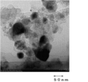
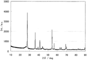
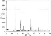
- the powder X-ray diffraction spectrum of the catalyst (1) is shown in FIG. Diffraction line peaks of titanium carbonitride with cubic structure and titanium oxide with rutile structure were observed.
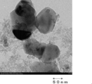
- FIG. 2 shows a TEM photograph of catalyst (1).
- the black portion represents the catalyst, and the thin portion represents carbon black.
- the molar ratio of the nitrogen-containing organic substance to the transition metal compound was 3.5, and the molar ratio of carbon black to the transition metal compound was 6.8.
- the powder X-ray diffraction spectrum of the catalyst (2) is shown in FIG. Diffraction line peaks of titanium carbonitride with cubic structure and titanium oxide with rutile structure were observed.
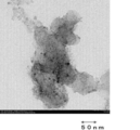
- FIG. 4 shows a TEM photograph of the catalyst (2).
- catalyst (3) (hereinafter also referred to as "catalyst (3)") powder was obtained in the same manner as in Example except that the amount of carbon black added was 1.42 g.
- the molar ratio of the nitrogen-containing organic substance to the transition metal compound was 3.5, and the molar ratio of carbon black to the transition metal compound was 8.9.
- the powder X-ray diffraction spectrum of the catalyst (3) is shown in FIG. Diffraction line peaks of titanium carbonitride with cubic structure and titanium oxide with rutile structure were observed.
- FIG. 6 shows a TEM photograph of the catalyst (3).
- Example 4 Preparation of catalyst Titanium tetraisopropoxide (Pure Chemical) 3.42 mL and acetylacetone (Pure Chemical) 3.59 mL and acetic acid (Wako Pure Chemical) 5.47 mL were added to a solution and stirred at room temperature. A titanium-containing mixture solution was prepared.
- ethylene diammonium dichloride (Wako Pure Chemical) and 0.262 g of chromium acetate (Aldrich) were added to a mixed solution of 75 mL of pure water and 50 mL of ethanol (Wako Pure Chemical) and stirred at room temperature to completely It was made to melt
- the titanium-containing mixture solution was slowly added to the ethylenediammonium dichloride-containing mixture solution to prepare a mixed solution.
- 1.065 g of carbon black (Ketjen Black EC300J, manufactured by LION) was added and stirred at room temperature for 1 hour.
- This carbon-containing mixed solution was evaporated to dryness with an evaporator, and the obtained solid was finely and uniformly crushed with a mortar to obtain a powder.
- This powder is heated at 900 ° C. for 1 hour in a rotary kiln while flowing a mixed gas of nitrogen gas and hydrogen gas having a mixing ratio of 4% by volume of hydrogen gas, so that at least titanium, carbon, nitrogen, and oxygen are contained.
- a contained catalyst hereinafter also referred to as “catalyst (4)” was obtained.
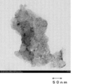
- FIG. 7 shows a TEM photograph of the catalyst (4).
- catalyst (5) The catalyst (hereinafter also referred to as "catalyst (5)") powder was prepared in the same manner as in Example 2 except that 0.199 g of iron acetate (manufactured by Aldrich) was not added. Obtained.
- Example 6 Preparation of catalyst The catalyst was prepared in the same manner as in Example 5 except that 2.87 mL of niobium ethoxide (manufactured by Aldrich) was added instead of 3.42 mL of titanium tetraisopropoxide (Pure Chemical). (Hereinafter also referred to as “catalyst (6)”) powder was obtained.
- the molar ratio of the nitrogen-containing organic substance to the transition metal compound was 4, and the molar ratio of carbon black to the transition metal compound was 7.4.
- catalyst (7) a catalyst (hereinafter referred to as "catalyst (7)") powder was obtained in the same manner as in Example 1 except that carbon black was not added.
- the powder X-ray diffraction spectrum of the catalyst (7) is shown in FIG. Diffraction line peaks of titanium carbonitride with cubic structure and titanium oxide with rutile structure were observed.
- FIG. 9 shows a TEM photograph of the catalyst (7).
- Electrode having fuel cell catalyst layer An electrode having a cathode catalyst layer (5) was prepared in the same manner as in Example 11 except that the cathode ink (5) was used instead of the cathode ink (1). did.
- Electrode having fuel cell catalyst layer An electrode having a cathode catalyst layer (7) was prepared in the same manner as in Example 11 except that the cathode ink (7) was used instead of the cathode ink (1). did.
- Electrode having fuel cell catalyst layer An electrode having a cathode catalyst layer (8) was prepared in the same manner as in Example 11 except that the cathode ink (8) was used instead of the cathode ink (1). did.
- MEA MEA (8) was produced in the same manner as in Example 11 except that the electrode having the cathode catalyst layer (8) was used instead of the electrode having the cathode catalyst layer (1).
- Electrode having fuel cell catalyst layer An electrode having a cathode catalyst layer (9) was prepared in the same manner as in Example 11 except that the cathode ink (9) was used instead of the cathode ink (1). did.
- MEA MEA (9) was produced in the same manner as in Example 11 except that an electrode having a cathode catalyst layer (9) was used instead of an electrode having a cathode catalyst layer (1).
- a cathode ink (10) was produced in the same manner as in Comparative Example 7, except that the fuel cell catalyst (20) was used instead of the fuel cell catalyst (13).
- Electrode having fuel cell catalyst layer An electrode having a cathode catalyst layer (10) was prepared in the same manner as in Example 11 except that the cathode ink (10) was used instead of the cathode ink (1). did.
- MEA MEA (10) was produced in the same manner as in Example 11 except that an electrode having a cathode catalyst layer (10) was used instead of an electrode having a cathode catalyst layer (1).
- unit cell (10) of a polymer electrolyte fuel cell was produced in the same manner as in Example 11 except that MEA (10) was used instead of MEA (1).
- a gas diffusion layer (carbon paper TGP-H-060, manufactured by Toray Industries, Inc.) was immersed in acetone for 30 seconds to perform degreasing. After drying, it was immersed in a 10% polytetrafluoroethylene (hereinafter also referred to as “PTFE”) aqueous solution for 30 seconds. After drying at room temperature, heating was performed at 350 ° C. for 1 hour to disperse PTFE inside the carbon paper to obtain a gas diffusion layer (hereinafter also referred to as “GDL”) having water repellency.
- PTFE polytetrafluoroethylene
- the anode ink (1) prepared in 1 above was applied to the surface of the GDL having a size of 5 cm ⁇ 5 cm at 80 ° C. by an automatic spray coating apparatus (manufactured by Saneitec Co., Ltd.). By repeatedly spraying, an electrode having an anode catalyst layer (1) having a Pt amount of 1 mg / cm 2 per unit area was produced.
- the maximum amount obtained from the current-potential characteristic curve is obtained by preparing a catalyst raw material by mixing carbon black in a specific ratio in addition to nitrogen-containing organic substance and metal salt, and preparing a catalyst It was found that the power density increased.
Landscapes
- Chemical & Material Sciences (AREA)
- Chemical Kinetics & Catalysis (AREA)
- Electrochemistry (AREA)
- General Chemical & Material Sciences (AREA)
- Engineering & Computer Science (AREA)
- Manufacturing & Machinery (AREA)
- Materials Engineering (AREA)
- Thermal Sciences (AREA)
- Physics & Mathematics (AREA)
- Composite Materials (AREA)
- Catalysts (AREA)
- Inert Electrodes (AREA)
- Life Sciences & Earth Sciences (AREA)
- Sustainable Development (AREA)
- Sustainable Energy (AREA)
- Fuel Cell (AREA)
Abstract
Description
(1)窒素含有有機物、遷移金属化合物および導電性粒子を溶媒に混合する工程(I)と、該工程(I)で得られた混合物を焼成する工程(II)とを含むことを特徴とする燃料電池用電極触媒の製造方法。
(2)前記導電性粒子がカーボンブラックあることを特徴とする前記(1)に記載の燃料電池用電極触媒の製造方法。
(3)前記工程(I)において、遷移金属化合物の総和に対するカーボンブラックのモル比が1~15であることを特徴とする前記(2)に記載の燃料電池用電極触媒の製造方法。
(4)前記窒素含有有機物が、アミノ基、ニトリル基、イミド基、イミン基、ニトロ基、アミド基、アジド基、アジリジン基、アゾ基、イソシアネート基、イソチオシアネート基、オキシム基、ジアゾ基、およびニトロソ基、ならびにピロール環、ポルフィリン環、イミダゾール環、ピリジン環、ピリミジン環、およびピラジン環から選ばれる1種類以上を分子中に有することを特徴とする前記(1)~(3)のいずれかに記載の燃料電池用電極触媒の製造方法。
(5)前記窒素含有有機物が、水酸基、カルボキシル基、アルデヒド基、酸ハライド基、スルホ基、リン酸基、ケトン基、エーテル基、およびエステル基から選ばれる1種類以上を分子中に有することを特徴とする前記(1)~(4)のいずれかに記載の燃料電池用電極触媒の製造方法。
(6)前記工程(I)において、遷移金属化合物の総和に対する窒素含有有機物のモル比が0.1~10であることを特徴とする前記(1)~(5)のいずれかに記載の燃料電池用電極触媒の製造方法。
(7)前記遷移金属化合物の金属が、チタン、バナジウム、クロム、マンガン、鉄、コバルト、銅、ジルコニウム、ニオブ、タンタルおよびタングステンからなる群から選ばれる少なくとも一種であることを特徴とする前記(1)~(6)のいずれか1項に記載の燃料電池用電極触媒の製造方法。
(8)前記遷移金属化合物が少なくとも二種の遷移金属の化合物であり、そのうち一種の遷移金属はチタン、ジルコニウム、ニオブおよびタンタルからなる群から選ばれ、他の一種は、バナジウム、クロム、マンガン、鉄、コバルト、銅およびタングステンからなる群から選ばれることを特徴とする前記(1)~(6)のいずれか1項に記載の燃料電池用電極触媒の製造方法。
(9)前記工程(I)が、前記窒素含有有機物、遷移金属化合物および導電性粒子を溶媒に混合して触媒前駆体混合液を得た後、該触媒前駆体混合液から溶媒を除去して前記混合物を得る工程であることを特徴とする前記(1)~(8)のいずれかに記載の燃料電池用電極触媒の製造方法。
(10)前記触媒前駆体混合液にジケトン構造を有する化合物からなる沈殿抑制剤を混合することを特徴とする前記(9)に記載の燃料電池用電極触媒の製造方法。
(11)前記工程(I)が、前記遷移金属化合物を溶媒に混合して得られた溶液と前記沈殿抑制剤とを混合し、次いで前記窒素含有有機物を混合し、その後前記導電性粒子を混合して前記触媒前駆体混合液を得た後、該触媒前駆体混合液から溶媒を除去して前記混合物を得る工程であることを特徴とする前記(9)または(10)に記載の燃料電池用電極触媒の製造方法。
(12)前記遷移金属化合物が、分子中に酸素原子を含む遷移金属化合物であることを特徴とする前記(1)~(11)に記載の燃料電池用電極触媒の製造方法。
(13)前記(1)~(12)のいずれかに記載の製造方法により得られることを特徴とする燃料電池用電極触媒。
(14)前記(13)に記載の燃料電池用電極触媒を含むことを特徴とする燃料電池用触媒層。
(15)前記(14)に記載の燃料電池用触媒層とガス拡散層とを有することを特徴とする電極。
(16)カソードとアノードと前記カソードおよび前記アノードの間に配置された電解質膜とを有する膜電極接合体であって、前記カソードおよび/または前記アノードが前記(15)に記載の電極であることを特徴とする膜電極接合体。
(17)前記(16)に記載の膜電極接合体を備えることを特徴とする燃料電池。
(18)前記(16)に記載の膜電極接合体を備えることを特徴とする固体高分子型燃料電池。
本発明の燃料電池用電極触媒の製造方法は、窒素含有有機物、遷移金属化合物および導電性粒子を溶媒に混合する工程(I)と、該工程(I)で得られた混合物を焼成する工程(II)とを含むことを特徴とする。
工程(I)は、窒素含有有機物、遷移金属化合物および導電性粒子を溶媒に混合する工程であり、好ましくは遷移金属化合物、窒素含有有機物、導電性粒子および溶媒を混合して混合液(本明細書において「触媒前駆体混合液」とも記す。)を得る工程(i)、および前記触媒前駆体混合液から溶媒を除去する工程(ii)を含む。工程(I)において、前記窒素含有有機物、遷移金属化合物、導電性粒子および溶媒の少なくともいずれか1つが酸素原子を有すると、炭素原子、窒素原子および酸素原子を構成原子として有する燃料電池用電極触媒を製造することができ、この燃料電池用電極触媒はより高い触媒活性を有するので好適である。
遷移金属化合物は、少なくとも一種の遷移金属の化合物である。前記遷移金属化合物が、一種の遷移金属の化合物である場合には、その遷移金属はチタン、バナジウム、クロム、マンガン、鉄、コバルト、銅、ジルコニウム、ニオブ、タンタルおよびタングステンからなる群から選ばれる。二種の遷移金属の化合物である場合には、そのうちの一種の遷移金属はチタン、ジルコニウム、ニオブおよびタンタルからなる群から選ばれ、他の一種の遷移金属はバナジウム、クロム、マンガン、鉄、コバルト、銅およびタングステンからなる群から選ばれる。
五酸化ニオブ、ニオブ1原子に対し2.5以下の酸素原子を有する酸化ニオブ、ニオブペンタメトキシド、ニオブペンタエトキシド、ニオブペンタイソプロポキシド、ニオブペンタブトキシド、ニオブペンタペントキシド、五塩化ニオブ、オキシ塩化ニオブ、五臭化ニオブ、オキシ臭化ニオブ、五ヨウ化ニオブ、オキシヨウ化ニオブ等のニオブ化合物;
二酸化ジルコニウム、ジルコニウム1原子に対し1以上2以下の酸素原子を有する酸化ジルコニウム、ジルコニウムテトラメトキシド、ジルコニウムテトラエトキシド、ジルコニウムテトラプロポキシド、ジルコニウムテトライソプロポキシド、ジルコニウムテトラブトキシド、ジルコニウムテトライソブトキシド、ジルコニウムテトラペントキシド、ジルコニウムテトラアセチルアセトナート、四塩化ジルコニウム、オキシ塩化ジルコニウム、四臭化ジルコニウム、オキシ臭化ジルコニウム、四ヨウ化ジルコニウム、オキシヨウ化ジルコニウム等のジルコニウム化合物;
五酸化タンタル、タンタル1原子に対し2.5以下の酸素原子を有する酸化タンタル、タンタルペンタメトキシド、タンタルペンタエトキシド、タンタルペンタイソプロポキシド、タンタルペンタブトキシド、タンタルペンタペントキシド、タンタルテトラエトキシアセチルアセトナート、五塩化タンタル、オキシ塩化タンタル、五臭化タンタル、オキシ臭化タンタル、五ヨウ化タンタル、オキシヨウ化タンタル等のタンタル化合物;
が挙げられる。
塩化クロム(II)、塩化クロム(III)、硫酸クロム(III)、硫化クロム(III)、硝酸クロム(III)、シュウ酸クロム(III)、リン酸クロム(III)、水酸化クロム(III)、酸化クロム(II)、酸化クロム(III)、酸化クロム(IV)、酸化クロム(VI)、酢酸クロム(II)、酢酸クロム(III)、乳酸クロム(III)等のクロム化合物;
塩化コバルト(II)、塩化コバルト(III)、硫酸コバルト(II)、硫化コバルト(II)、硝酸コバルト(II)、硝酸コバルト(III)、シュウ酸コバルト(II)、リン酸コバルト(II)、コバルトセン、水酸化コバルト(II)、酸化コバルト(II)、酸化コバルト(III)、四酸化三コバルト、酢酸コバルト(II)、乳酸コバルト(II)等のコバルト化合物;
塩化バナジウム(II)、塩化バナジウム(III)、塩化バナジウム(IV)、オキシ硫酸バナジウム(IV)、硫化バナジウム(III)、オキシシュウ酸バナジウム(IV)、バナジウムメタロセン、酸化バナジウム(V)、酢酸バナジウム、クエン酸バナジウム等のバナジウム化合物;
塩化マンガン(II)、硫酸マンガン(II)、硫化マンガン(II)、硝酸マンガン(II)、シュウ酸マンガン(II)、水酸化マンガン(II)、酸化マンガン(II)、酸化マンガン(III)、酢酸マンガン(II)、乳酸マンガン(II)、クエン酸マンガン等のマンガン化合物が挙げられる。
ジルコニウムテトラエトキシド、四塩化ジルコニウム、オキシ塩化ジルコニウム、ジルコニウムテトライソプロポキシド、ジルコニウムテトラアセチルアセトナート、
タンタルペンタメトキシド、タンタルペンタエトキシド、五塩化タンタル、オキシ塩化タンタル、タンタルペンタイソプロポキシド、およびタンタルテトラエトキシアセチルアセトナート、塩化鉄(II)、塩化鉄(III)、フェロシアン化カリウム、フェリシアン化カリウム、フェロシアン化アンモニウム、フェリシアン化アンモニウム、酢酸鉄(II)、乳酸鉄(II)、塩化クロム(II)、塩化クロム(III)、酢酸クロム(II)、酢酸クロム(III)、乳酸クロム(III)、塩化コバルト(II)、塩化コバルト(III)、酢酸コバルト(II)、乳酸コバルト(II)、塩化バナジウム(II)、塩化バナジウム(III)、塩化バナジウム(IV)、オキシ硫酸バナジウム(IV)、酢酸バナジウム、クエン酸バナジウム、塩化マンガン(II)、酢酸マンガン(II)、乳酸マンガン(II)が好ましく、チタンテトライソプロポキシド、チタンテトラアセチルアセトナート、ニオブエトキシド、ニオブイソプロポキシド、オキシ塩化ジルコニウム、ジルコニウムテトライソプロポキシド、およびタンタルペンタイソプロポキシド、塩化鉄(II)、塩化鉄(III)、フェロシアン化カリウム、フェリシアン化カリウム、フェロシアン化アンモニウム、フェリシアン化アンモニウム、酢酸鉄(II)、乳酸鉄(II)、塩化クロム(II)、塩化クロム(III)、酢酸クロム(II)、酢酸クロム(III)、乳酸クロム(III)がさらに好ましい。
前記窒素含有有機物としては、前記遷移金属化合物中の金属原子に配位可能な配位子となり得る化合物が好ましく、単核の錯体を形成し得る化合物がより好ましい。さらには、多座配位子となり得る化合物、つまりキレートを形成し得る化合物が好ましく、その中でも、2座配位子または3座配位子となり得る化合物がさらに好ましい。窒素含有有機物が、キレートを形成し得る化合物であると、金属と錯形成し、金属と有機物が分子レベルで均一に分散するという利点がある。キレートを形成し得る化合物としては、たとえば、アミノ酸、アミン化合物、ジケトン化合物、アミノアルコール、フェノール誘導体、複素環式化合物等を挙げることができる。
前記溶媒としては、たとえば水、アルコール類および酸類が挙げられる。アルコール類としては、エタノール、メタノール、ブタノール、プロパノールおよびエトキシエタノールが好ましく、エタノールおよびメタノールさらに好ましい。酸類としては、酢酸、硝酸、塩酸、リン酸およびクエン酸が好ましく、酢酸および硝酸がさらに好ましい。これらは、1種単独で用いてもよく2種以上を併用してもよい。
前記遷移金属化合物が、塩化チタン、塩化ニオブ、塩化ジルコニウム、塩化タンタルなど、ハロゲン原子を含む場合には、これらの化合物は一般的に水によって容易に加水分解され、水酸化物や、酸塩化物等の沈殿を生じやすい。よって、前記遷移金属化合物がハロゲン原子を含む場合は、沈殿抑制剤として強酸を1質量%以上という高濃度で添加することが好ましい。たとえば酸が塩酸であれば、溶液中の塩化水素の濃度が5質量%以上、より好ましくは10質量%以上となるように酸を添加すると、前記遷移金属化合物に由来する沈殿がない触媒前駆体混合液を得ることができる。
導電性粒子としては、導電性および安定性が高く、表面積が広いものであれば、特に限定されないが、例えば、炭素、導電性高分子、導電性セラミクス、金属または酸化タングステンもしくは酸化イリジウムなどの導電性無機酸化物が挙げられ、それらを単独または組み合わせて用いることができる。特に、炭素からなる導電性粒子は比表面積が大きいため、また、安価に小粒径のものを入手しやすく、耐薬品性、耐高電位性に優れるため好ましい。炭素からなる導電性粒子を用いる場合、炭素単独または炭素とその他の導電性粒子との混合物が好ましい。炭素としては、カーボンブラック、グラファイト、活性炭、カーボンナノチューブ、カーボンナノファイバー、カーボンナノホーン、フラーレン、多孔体カーボン、グラフェンなどが挙げられる。炭素からなる導電性粒子の粒子径、ストラクチャーおよび表面性状については特に制限はないが、小さすぎると電子伝導パスが形成されにくくなり、また大きすぎると燃料電池用触媒層のガス拡散性の低下や触媒の利用率の低下が起こる傾向があるため、TEM観察により求められるその平均粒子径は、好ましくは1~1000nmであり、より好ましくは10~100nmである。
工程(II)においては工程(I)で得られた混合物を焼成する。
本発明の燃料電池用電極触媒は、上述した本発明の燃料電池用電極触媒の製造方法により製造されることを特徴としている。
該触媒とNAFION(登録商標)(デュポン社 5%NAFION(登録商標)溶液(DE521))を溶剤中に入れ、超音波で攪拌し懸濁液を得る。なお、溶剤としては、イソプロピルアルコール:水(質量比)=1:1を用いる。
本発明において、酸素還元電流密度は、以下のとおり求めることができる。
本発明の燃料電池用電極触媒は、白金触媒の代替触媒として使用することができる。
本発明の燃料電池を備えることができる前記物品の具体例としては、ビル、家屋、テント等の建築物、蛍光灯、LED等、有機EL、街灯、屋内照明、信号機等の照明器具、機械、車両そのものを含む自動車用機器、家電製品、農業機器、電子機器、携帯電話等を含む携帯情報端末、美容機材、可搬式工具、風呂用品トイレ用品等の衛生機材、家具、玩具、装飾品、掲示板、クーラーボックス、屋外発電機などのアウトドア用品、教材、造花、オブジェ、心臓ペースメーカー用電源、ペルチェ素子を備えた加熱および冷却器用の電源が挙げられる。
1.粉末X線回折
理学電機株式会社製 ロータフレックスを用いて、試料の粉末X線回折を行った。
得られた製造物をエタノールに分散し、銅製マイクログリッドを浸漬、風乾させることで準備した。日立製透過型電子顕微鏡 H-9500(加速電圧300kV)を使用し、倍率を50.0K±10%に設定し、10視野を測定し、それぞれ画像解析を行った。画像解析は、粒子系画像解析ソフトLUZEX APを使用して行った。
チタンテトライソプロポキシド(純正化学)3.42mLおよびアセチルアセトン(純正化学)3.59mLと酢酸(和光純薬)5.47mLとの溶液に加え、室温で攪拌しながらチタン含有混合物溶液を作成した。また、グリシン(和光純薬)3.43gおよび酢酸鉄(Aldrich社製)0.199gを純水75mLとエタノール(和光純薬)50mLの混合溶液に加え、室温で攪拌して完全に溶解させてグリシン含有混合物溶液を作成した。チタン含有混合物溶液をグリシン含有混合物溶液にゆっくり添加し、混合溶液を作製した。この混合溶液に、カーボンブラック(ケッチェンブラックEC300J、LION社製)0.71gを加え、室温で1時間攪拌した。このカーボン含有混合溶液をエバポレーターによって蒸発乾固させ、得られた固形物を乳鉢で細かく、均一に潰して粉末を得た。
カーボンブラックの添加量を1.065gにしたこと以外は実施例と同様に行い、触媒(以下「触媒(2)」とも記す。)の粉末を得た。
図4に、触媒(2)のTEM写真を示す。
カーボンブラックの添加量を1.42gにしたこと以外は実施例と同様に行い、触媒(以下「触媒(3)」とも記す。)の粉末を得た。
チタンテトライソプロポキシド(純正化学)3.42mLおよびアセチルアセトン(純正化学)3.59mLと酢酸(和光純薬)5.47mLとの溶液に加え、室温で攪拌しながらチタン含有混合物溶液を作成した。また、エチレンジアンモニウムジクロリド(和光純薬)3.04gおよび酢酸クロム(Aldrich社製)0.262gを純水75mLとエタノール(和光純薬)50mLの混合溶液に加え、室温で攪拌して完全に溶解させてエチレンジアンモニウムジクロリド含有混合物溶液を作成した。チタン含有混合物溶液をエチレンジアンモニウムジクロリド含有混合物溶液にゆっくり添加し、混合溶液を作製した。この混合溶液に、カーボンブラック(ケッチェンブラックEC300J、LION社製)1.065gを加え、室温で1時間攪拌した。このカーボン含有混合溶液をエバポレーターによって蒸発乾固させ、得られた固形物を乳鉢で細かく、均一に潰して粉末を得た。この粉末を、水素ガスの混合比率が4容量%である窒素ガスと水素ガスとの混合ガスを流しながら、ロータリーキルンで、900℃、1時間加熱することにより、チタン、炭素、窒素、酸素を少なくとも含有する触媒(以下「触媒(4)」とも記す。)を得た。
図7に、触媒(4)のTEM写真を示す。
酢酸鉄(Aldrich社製)0.199gを添加しなかったこと以外は実施例2と同様に行い、触媒(以下「触媒(5)」とも記す。)の粉末を得た。
チタンテトライソプロポキシド(純正化学)3.42mLの代わりに、ニオビウムエトキシド(Aldrich社製)2.87mLを添加したこと以外は実施例5と同様に行い、触媒(以下「触媒(6)」とも記す。)の粉末を得た。
カーボンブラックを添加しなかったこと以外は実施例1と同様に行い、触媒(以下「触媒(7)」とも記す。)の粉末を得た。
カーボンブラックを添加しなかったこと以外は実施例4と同様に行い、触媒(以下「触媒(8)」とも記す。)の粉末を得た。
カーボンブラックを添加しなかったこと以外は実施例5と同様に行い、触媒(以下「触媒(9)」とも記す。)の粉末を得た。
カーボンブラックを添加しなかったこと以外は実施例6と同様に行い、触媒(以下「触媒(10)」とも記す。)の粉末を得た。
1.燃料電池用電極の製造
触媒(1)0.015gに、イソプロピルアルコール:純水=1:1の容積比で混合した溶液1212μlとNAFION(登録商標)(デュポン社 5%NAFION(登録商標)溶液(DE521))37.5μlを入れ、超音波で分散させ、懸濁液とした。この懸濁液を、超音波をかけながら10μLを採取し、すばやくグラッシーカーボン電極(直径:5.2mm)上に滴下し、60℃で5分間乾燥させた。この滴下および乾燥操作を、カーボン電極表面に1.0mgの燃料電池触媒層が形成されるまで行い、燃料電池用電極(1)を得た。
作製した燃料電池用電極(1)を、酸素雰囲気および窒素雰囲気で、0.5mol/dm3の硫酸溶液中、30℃、5mV/秒の電位走査速度で分極し、電流-電位曲線を測定した。その際、同濃度の硫酸溶液中での可逆水素電極を参照電極とした。
1.燃料電池用電極の製造
触媒(1)の替わりに触媒(2)を使用したこと以外は実施例7と同様に行い、燃料電池用電極(2)を得た。
燃料電池用電極(1)の替わりに燃料電池用電極(2)を使用したこと以外は実施例7と同様に行い、酸素還元電流密度(mA/cm2)@0.8Vを測定した。
1.燃料電池用電極の製造
触媒(1)の替わりに触媒(3)を使用したこと以外は実施例7と同様に行い、燃料電池用電極(3)を得た。
燃料電池用電極(1)の替わりに燃料電池用電極(3)を使用したこと以外は実施例7と同様に行い、酸素還元電流密度(mA/cm2)@0.8Vを測定した。
1.燃料電池用電極の製造
触媒(1)の替わりに触媒(4)を使用したこと以外は実施例7と同様に行い、燃料電池用電極(4)を得た。
燃料電池用電極(1)の替わりに燃料電池用電極(4)を使用したこと以外は実施例7と同様に行い、酸素還元電流密度(mA/cm2)@0.8Vを測定した。
1.燃料電池用電極の製造
触媒(7)0.012gとカーボンブラック(ケッチェンブラックEC300J、LION社製)0.003gの混合物に、イソプロピルアルコール:純水=1:1の容積比で混合した溶液1212μlとNAFION(登録商標)(デュポン社 5%NAFION(登録商標)溶液(DE521))37.5μlを入れ、超音波で分散させ、懸濁液とした。この懸濁液を、超音波をかけながら10μLを採取し、すばやくグラッシーカーボン電極(直径:5.2mm)上に滴下し、60℃で5分間乾燥させた。この滴下および乾燥操作を、カーボン電極表面に1.0mgの燃料電池触媒層が形成されるまで行い、燃料電池用電極(5)を得た。
燃料電池用電極(1)の替わりに燃料電池用電極(5)を使用したこと以外は実施例7と同様に行い、酸素還元電流密度(mA/cm2)@0.8Vを測定した。
1.燃料電池用電極の製造
触媒(7)の替わりに触媒(8)を使用したこと以外は比較例5と同様に行い、燃料電池用電極(6)を得た。
燃料電池用電極(1)の替わりに燃料電池用電極(6)を使用したこと以外は実施例7と同様に行い、酸素還元電流密度(mA/cm2)@0.8Vを測定した。
1.インクの調製
触媒(5)を、遊星ボールミル(フリッチェ社製 Premium7、自転半径:2.3cm、公転半径:16.3cm)により以下のとおり解砕した。
ガス拡散層(カーボンペーパーTGP-H-060、東レ社製)を、アセトンに30秒間浸漬し、脱脂を行った。乾燥後、10%のポリテトラフルオロエチレン(以下「PTFE」とも記す。)水溶液に30秒間浸漬した。
電解質膜として、Nafion膜N-212(DuPont社製)を用いた。カソードとして、上記2で作製したGDLの表面にカソード触媒層(1)を有する電極を用いた。アノードとして、参考例1で作製したGDLの表面にアノード触媒層(1)を有する電極を用いた。
上記3で作製したMEA(1)を、2つシール材(ガスケット)、2つのガス流路付きセパレーター、2つの集電板およびで2つのラバーヒータで挟んでボルトで固定し、所定の面圧(4N)になるように締め付けて、固体高分子形燃料電池の単セル(1)(25cm2)を作製した。
上記4で作製した単セル(1)を90℃、アノード加湿器を90℃、カソード加湿器を50℃に温度調節した。アノード側に燃料として水素を流量1リットル/分で供給し、カソード側に酸化剤として酸素を流量2リットル/分で供給し、両側ともに300kPaの背圧をかけながら、単セル(1)における電流―電圧特性を測定した。得られた電流―電圧特性曲線から最大出力密度を算出した。当該最大出力密度が大きいほど、MEAにおける触媒能が高いことを示す。MEA(1)における触媒能、すなわち最大出力密度は、162mW/cm2であった。
1.インクの調製
触媒(5)の代わりに触媒(6)を用いた以外は、実施例11と同様にして、燃料電池用触媒(12)を作製した。
カソード用インク(1)の代わりにカソード用インク(2)を用いた以外は、実施例11と同様にして、カソード触媒層(2)を有する電極を作製した。
カソード触媒層(1)を有する電極の代わりにカソード触媒層(2)を有する電極を用いた以外は、実施例11と同様にして、MEA(2)を作製した。
MEA(1)の代わりにMEA(2)を用いた以外は、実施例11と同様にして、固体高分子形燃料電池の単セル(2)を作製した。
単セル(1)の代わりに単セル(2)を用いた以外は、実施例11と同様にして、単セル(2)における電流―電圧特性を測定し、最大出力密度を算出した。MEA(2)における触媒能、すなわち最大出力密度は、101mW/cm2であった。
1.インクの調製
触媒(5)の代わりに触媒(9)を用いた以外は、実施例11と同様にして、燃料電池用触媒(13)を作製した。
カソード用インク(1)の代わりにカソード用インク(3)を用いた以外は、実施例11と同様にして、単位面積あたりの触媒(13)とカーボンブラックの総量が5mg/cm2のカソード触媒層(3)を有する電極を作製した。
カソード触媒層(1)を有する電極の代わりにカソード触媒層(3)を有する電極を用いた以外は、実施例11と同様にして、MEA(3)を作製した。
MEA(1)の代わりにMEA(3)を用いた以外は、実施例11と同様にして、固体高分子形燃料電池の単セル(3)を作製した。
単セル(1)の代わりに単セル(3)を用いた以外は、実施例11と同様にして、単セル(3)における電流―電圧特性を測定し、最大出力密度を算出した。MEA(3)における触媒能、すなわち最大出力密度は、76mW/cm2であった。
1.インクの調製
触媒(1)の代わりに触媒(10)を用いた以外は、実施例11と同様にして、燃料電池用触媒(14)を作製した。
カソード用インク(1)の代わりにカソード用インク(4)を用いた以外は、実施例11と同様にして、カソード触媒層(4)を有する電極を作製した。
カソード触媒層(1)を有する電極の代わりにカソード触媒層(4)を有する電極を用いた以外は、実施例11と同様にして、MEA(4)を作製した。
MEA(1)の代わりにMEA(4)を用いた以外は、実施例11と同様にして、固体高分子形燃料電池の単セル(4)を作製した。
単セル(1)の代わりに単セル(4)を用いた以外は、実施例11と同様にして、単セル(4)における電流―電圧特性を測定し、最大出力密度を算出した。MEA(4)における触媒能、すなわち最大出力密度は、53mW/cm2であった。
第二金属として鉄の効果を検証した。
触媒(5)の代わりに触媒(1)を用いた以外は、実施例11と同様にして、燃料電池用触媒(15)を作製した。
カソード用インク(1)の代わりにカソード用インク(5)を用いた以外は、実施例11と同様にして、カソード触媒層(5)を有する電極を作製した。
カソード触媒層(1)を有する電極の代わりにカソード触媒層(5)を有する電極を用いた以外は、実施例11と同様にして、MEA(5)を作製した。
MEA(1)の代わりにMEA(5)を用いた以外は、実施例11と同様にして、固体高分子形燃料電池の単セル(5)を作製した。
単セル(1)の代わりに単セル(5)を用いた以外は、実施例11と同様にして、単セル(5)における電流―電圧特性を測定し、最大出力密度を算出した。MEA(5)における触媒能、すなわち最大出力密度は、688mW/cm2であった。
第二金属として鉄の効果を検証した。
触媒(5)の代わりに触媒(2)を用いた以外は、実施例11と同様にして、燃料電池用触媒(16)を作製した。
カソード用インク(1)の代わりにカソード用インク(6)を用いた以外は、実施例11と同様にして、カソード触媒層(6)を有する電極を作製した。
カソード触媒層(1)を有する電極の代わりにカソード触媒層(6)を有する電極を用いた以外は、実施例11と同様にして、MEA(6)を作製した。
MEA(1)の代わりにMEA(6)を用いた以外は、実施例11と同様にして、固体高分子形燃料電池の単セル(6)を作製した。
単セル(1)の代わりに単セル(6)を用いた以外は、実施例11と同様にして、単セル(6)における電流―電圧特性を測定し、最大出力密度を算出した。MEA(6)における触媒能、すなわち最大出力密度は、742mW/cm2であった。
第二金属として鉄の効果を検証した。
触媒(5)の代わりに触媒(3)を用いた以外は、実施例11と同様にして、燃料電池用触媒(17)を作製した。
カソード用インク(1)の代わりにカソード用インク(7)を用いた以外は、実施例11と同様にして、カソード触媒層(7)を有する電極を作製した。
カソード触媒層(1)を有する電極の代わりにカソード触媒層(7)を有する電極を用いた以外は、実施例11と同様にして、MEA(7)を作製した。
MEA(1)の代わりにMEA(7)を用いた以外は、実施例11と同様にして、固体高分子形燃料電池の単セル(7)を作製した。
単セル(1)の代わりに単セル(7)を用いた以外は、実施例11と同様にして、単セル(7)における電流―電圧特性を測定し、最大出力密度を算出した。MEA(7)における触媒能、すなわち最大出力密度は、643mW/cm2であった。
1.インクの調製
触媒(5)の代わりに触媒(7)を用いた以外は、実施例11と同様にして、燃料電池用触媒(18)を作製した。
カソード用インク(1)の代わりにカソード用インク(8)を用いた以外は、実施例11と同様にして、カソード触媒層(8)を有する電極を作製した。
カソード触媒層(1)を有する電極の代わりにカソード触媒層(8)を有する電極を用いた以外は、実施例11と同様にして、MEA(8)を作製した。
MEA(1)の代わりにMEA(8)を用いた以外は、実施例11と同様にして、固体高分子形燃料電池の単セル(8)を作製した。
単セル(1)の代わりに単セル(8)を用いた以外は、実施例11と同様にして、単セル(8)における電流―電圧特性を測定し、最大出力密度を算出した。MEA(8)における触媒能、すなわち最大出力密度は、520mW/cm2であった。
第二金属としてクロムの効果を検証した。
触媒(5)の代わりに触媒(4)を用いた以外は、実施例11と同様にして、燃料電池用触媒(19)を作製した。
カソード用インク(1)の代わりにカソード用インク(9)を用いた以外は、実施例11と同様にして、カソード触媒層(9)を有する電極を作製した。
カソード触媒層(1)を有する電極の代わりにカソード触媒層(9)を有する電極を用いた以外は、実施例11と同様にして、MEA(9)を作製した。
MEA(1)の代わりにMEA(9)を用いた以外は、実施例11と同様にして、固体高分子形燃料電池の単セル(9)を作製した。
単セル(1)の代わりに単セル(9)を用いた以外は、実施例11と同様にして、単セル(9)における電流―電圧特性を測定し、最大出力密度を算出した。MEA(9)における触媒能、すなわち最大出力密度は、532mW/cm2であった。
1.インクの調製
触媒(5)の代わりに触媒(8)を用いた以外は、実施例11と同様にして、燃料電池用触媒(20)を作製した。
カソード用インク(1)の代わりにカソード用インク(10)を用いた以外は、実施例11と同様にして、カソード触媒層(10)を有する電極を作製した。
カソード触媒層(1)を有する電極の代わりにカソード触媒層(10)を有する電極を用いた以外は、実施例11と同様にして、MEA(10)を作製した。
MEA(1)の代わりにMEA(10)を用いた以外は、実施例11と同様にして、固体高分子形燃料電池の単セル(10)を作製した。
単セル(1)の代わりに単セル(10)を用いた以外は、実施例11と同様にして、単セル(10)における電流―電圧特性を測定し、最大出力密度を算出した。MEA(10)における触媒能、すなわち最大出力密度は、342mW/cm2であった。
1.アノード用インクの調製
Pt担持カーボン(TEC10E60E、田中貴金属工業製)0.6gを純水50mlに加え、さらにプロトン伝導性材料(NAFION(登録商標);0.25g)を含有する水溶液(Nafion5%水溶液、和光純薬工業製)5gを入れて、超音波分散機(UT-106H型シャープマニファクチャリングシステム社製)で1時間混合することにより、アノード用インク(1)を調製した。
ガス拡散層(カーボンペーパーTGP-H-060、東レ社製)を、アセトンに30秒間浸漬し、脱脂を行った。乾燥後、10%のポリテトラフルオロエチレン(以下「PTFE」とも記す。)水溶液に30秒間浸漬した。室温乾燥後、350℃で1時間加熱することにより、カーボンペーパー内部にPTFEを分散させ、撥水性を持たせたガス拡散層(以下「GDL」とも記す。)を得た。

Claims (18)
- 窒素含有有機物、遷移金属化合物および導電性粒子を溶媒に混合する工程(I)と、該工程(I)で得られた混合物を焼成する工程(II)とを含むことを特徴とする燃料電池用電極触媒の製造方法。
- 前記導電性粒子がカーボンブラックあることを特徴とする請求項1に記載の燃料電池用電極触媒の製造方法。
- 前記工程(I)において、遷移金属化合物の総和に対するカーボンブラックのモル比が1~15であることを特徴とする請求項2に記載の燃料電池用電極触媒の製造方法。
- 前記窒素含有有機物が、アミノ基、ニトリル基、イミド基、イミン基、ニトロ基、アミド基、アジド基、アジリジン基、アゾ基、イソシアネート基、イソチオシアネート基、オキシム基、ジアゾ基、およびニトロソ基、ならびにピロール環、ポルフィリン環、イミダゾール環、ピリジン環、ピリミジン環、およびピラジン環から選ばれる1種類以上を分子中に有することを特徴とする請求項1~3のいずれかに記載の燃料電池用電極触媒の製造方法。
- 前記窒素含有有機物が、水酸基、カルボキシル基、アルデヒド基、酸ハライド基、スルホ基、リン酸基、ケトン基、エーテル基、およびエステル基から選ばれる1種類以上を分子中に有することを特徴とする請求項1~4のいずれかに記載の燃料電池用電極触媒の製造方法。
- 前記工程(I)において、遷移金属化合物の総和に対する窒素含有有機物のモル比が0.1~10であることを特徴とする請求項1~5のいずれかに記載の燃料電池用電極触媒の製造方法。
- 前記遷移金属化合物の金属が、チタン、バナジウム、クロム、マンガン、鉄、コバルト、銅、ジルコニウム、ニオブ、タンタルおよびタングステンからなる群から選ばれる少なくとも一種であることを特徴とする請求項1~6のいずれか1項に記載の燃料電池用電極触媒の製造方法。
- 前記遷移金属化合物が少なくとも二種の遷移金属の化合物であり、そのうち一種の遷移金属はチタン、ジルコニウム、ニオブおよびタンタルからなる群から選ばれ、他の一種は、バナジウム、クロム、マンガン、鉄、コバルト、銅およびタングステンからなる群から選ばれることを特徴とする請求項1~6のいずれかに記載の燃料電池用電極触媒の製造方法。
- 前記工程(I)が、前記窒素含有有機物、遷移金属化合物および導電性粒子を溶媒に混合して触媒前駆体混合液を得た後、該触媒前駆体混合液から溶媒を除去して前記混合物を得る工程であることを特徴とする請求項1~8のいずれかに記載の燃料電池用電極触媒の製造方法。
- 前記触媒前駆体混合液にジケトン構造を有する化合物からなる沈殿抑制剤を混合することを特徴とする請求項9に記載の燃料電池用電極触媒の製造方法。
- 前記工程(I)が、前記遷移金属化合物を溶媒に混合して得られた溶液と前記沈殿抑制剤とを混合し、次いで前記窒素含有有機物を混合し、その後前記導電性粒子を混合して前記触媒前駆体混合液を得た後、該触媒前駆体混合液から溶媒を除去して前記混合物を得る工程であることを特徴とする請求項9または10に記載の燃料電池用電極触媒の製造方法。
- 前記遷移金属化合物が、分子中に酸素原子を含む遷移金属化合物であることを特徴とする請求項1~11のいずれかに記載の燃料電池用電極触媒の製造方法。
- 請求項1~12のいずれかに記載の製造方法により得られることを特徴とする燃料電池用電極触媒。
- 請求項13に記載の燃料電池用電極触媒を含むことを特徴とする燃料電池用触媒層。
- 請求項14に記載の燃料電池用触媒層とガス拡散層とを有することを特徴とする電極。
- カソードとアノードと前記カソードおよび前記アノードの間に配置された電解質膜とを有する膜電極接合体であって、前記カソードおよび/または前記アノードが請求項15に記載の電極であることを特徴とする膜電極接合体。
- 請求項16に記載の膜電極接合体を備えることを特徴とする燃料電池。
- 請求項16に記載の膜電極接合体を備えることを特徴とする固体高分子型燃料電池。
Priority Applications (6)
| Application Number | Priority Date | Filing Date | Title |
|---|---|---|---|
| JP2012527540A JP5148020B2 (ja) | 2010-12-22 | 2011-12-19 | 燃料電池用電極触媒の製造方法およびその用途 |
| KR1020137019005A KR101618928B1 (ko) | 2010-12-22 | 2011-12-19 | 연료 전지용 전극 촉매의 제조 방법 및 그 용도 |
| US13/996,124 US9570755B2 (en) | 2010-12-22 | 2011-12-19 | Production process for electrode catalyst for fuel cell and uses thereof |
| CN201180060909.0A CN103262320B (zh) | 2010-12-22 | 2011-12-19 | 燃料电池用电极催化剂的制造方法和其用途 |
| EP11852004.8A EP2658018B1 (en) | 2010-12-22 | 2011-12-19 | Production process for electrode catalyst for fuel cell and uses thereof |
| KR1020167005151A KR101880373B1 (ko) | 2010-12-22 | 2011-12-19 | 연료 전지용 전극 촉매의 제조 방법 및 그 용도 |
Applications Claiming Priority (2)
| Application Number | Priority Date | Filing Date | Title |
|---|---|---|---|
| JP2010-285729 | 2010-12-22 | ||
| JP2010285729 | 2010-12-22 |
Publications (1)
| Publication Number | Publication Date |
|---|---|
| WO2012086597A1 true WO2012086597A1 (ja) | 2012-06-28 |
Family
ID=46313867
Family Applications (1)
| Application Number | Title | Priority Date | Filing Date |
|---|---|---|---|
| PCT/JP2011/079395 Ceased WO2012086597A1 (ja) | 2010-12-22 | 2011-12-19 | 燃料電池用電極触媒の製造方法およびその用途 |
Country Status (6)
| Country | Link |
|---|---|
| US (1) | US9570755B2 (ja) |
| EP (1) | EP2658018B1 (ja) |
| JP (2) | JP5148020B2 (ja) |
| KR (2) | KR101880373B1 (ja) |
| CN (2) | CN103262320B (ja) |
| WO (1) | WO2012086597A1 (ja) |
Cited By (2)
| Publication number | Priority date | Publication date | Assignee | Title |
|---|---|---|---|---|
| JP2016037404A (ja) * | 2014-08-05 | 2016-03-22 | 旭化成ケミカルズ株式会社 | 炭素材料複合体、窒素含有炭素材料、及びそれらの製造方法 |
| CN119549174A (zh) * | 2024-10-16 | 2025-03-04 | 广东工业大学 | 一种一维纳米反应器及其制备方法与应用 |
Families Citing this family (8)
| Publication number | Priority date | Publication date | Assignee | Title |
|---|---|---|---|---|
| JP5706595B1 (ja) * | 2013-07-12 | 2015-04-22 | 昭和電工株式会社 | 酸素還元触媒、その用途およびその製造方法 |
| JP6217754B2 (ja) * | 2013-09-27 | 2017-10-25 | 日立化成株式会社 | 燃料電池用電極触媒、その製造方法、および燃料電池用電極触媒を用いた膜電極接合体 |
| JP6634340B2 (ja) * | 2016-05-12 | 2020-01-22 | 昭和電工株式会社 | 酸素還元触媒の製造方法 |
| CN106450355A (zh) * | 2016-11-01 | 2017-02-22 | 首都师范大学 | 一种氧还原催化剂及其制备方法 |
| US11680329B2 (en) * | 2019-10-01 | 2023-06-20 | King Fahd University Of Petroleum And Minerals | Manganese oxide nanoparticle carbon microparticle electrocatalyst and method of making from Albizia procera leaf |
| CN115244740A (zh) * | 2020-03-06 | 2022-10-25 | 日产化学株式会社 | 新型催化剂组合物以及具有含氮基团的碳材料 |
| CN111755725B (zh) * | 2020-06-17 | 2021-11-26 | 鄂尔多斯市国科能源有限公司 | 包含自交联离子聚合物的膜电极组件及其制备方法 |
| CN115172769A (zh) * | 2022-07-29 | 2022-10-11 | 华南理工大学 | 一种自支撑微生物燃料电池阳极及其制备方法与应用 |
Citations (4)
| Publication number | Priority date | Publication date | Assignee | Title |
|---|---|---|---|---|
| JP2005063749A (ja) * | 2003-08-08 | 2005-03-10 | Mitsubishi Gas Chem Co Inc | 燃料電池電極用触媒の製造方法及びその用途 |
| JP2006181541A (ja) * | 2004-12-28 | 2006-07-13 | Nissan Motor Co Ltd | 電極触媒の製造方法 |
| JP2007273371A (ja) * | 2006-03-31 | 2007-10-18 | Nittetsu Gijutsu Joho Center:Kk | 酸素還元複合触媒及びその製造方法並びにこれを用いた燃料電池 |
| JP2008251413A (ja) | 2007-03-30 | 2008-10-16 | Gunma Univ | 金属酸化物担持カーボンの製造方法 |
Family Cites Families (19)
| Publication number | Priority date | Publication date | Assignee | Title |
|---|---|---|---|---|
| KR100951345B1 (ko) | 2005-02-18 | 2010-04-08 | 지엠 글로벌 테크놀러지 오퍼레이션스, 인코포레이티드 | 연료전지용 내산화성 전극 |
| US7892299B2 (en) | 2005-09-15 | 2011-02-22 | Headwaters Technology Innovation, Llc | Methods of manufacturing fuel cell electrodes incorporating highly dispersed nanoparticle catalysts |
| AU2007217054A1 (en) * | 2006-02-17 | 2007-08-30 | Monsanto Technology Llc | Transition metal-containing catalysts and processes for their preparation and use as fuel cell catalysts |
| JP2007257888A (ja) | 2006-03-20 | 2007-10-04 | Allied Material Corp | 固体高分子形燃料電池用酸素極触媒およびそれを用いた酸素還元電極およびそれらの製造方法 |
| CN100391612C (zh) * | 2006-03-30 | 2008-06-04 | 上海交通大学 | 一种碳载钴卟啉氧还原催化剂的制备方法 |
| JP4142092B2 (ja) | 2006-12-13 | 2008-08-27 | 財団法人川村理化学研究所 | ドーピング酸化チタンの製造方法、ドーピング酸化チタン及びこれを用いる可視光応答型光触媒 |
| EP2523243A1 (en) | 2007-03-09 | 2012-11-14 | Sumitomo Chemical Company, Limited | Membrane-electrode assembly and fuel battery using the same |
| JP2008258152A (ja) * | 2007-03-09 | 2008-10-23 | Sumitomo Chemical Co Ltd | 膜−電極接合体およびこれを用いた燃料電池 |
| EP2178142A4 (en) | 2007-07-31 | 2014-04-30 | Showa Denko Kk | METAL OXIDE ELECTRODE CATALYST, ITS USE AND METHOD FOR PRODUCING A METAL OXIDE ELECTRODE CATALYST |
| JP5578849B2 (ja) * | 2007-09-07 | 2014-08-27 | 昭和電工株式会社 | 触媒およびその製造方法ならびにその用途 |
| JP5144244B2 (ja) | 2007-12-20 | 2013-02-13 | 昭和電工株式会社 | 電極触媒およびその用途、ならびに電極触媒の製造方法 |
| KR101202104B1 (ko) | 2008-02-28 | 2012-11-15 | 쇼와 덴코 가부시키가이샤 | 촉매 및 그 제조 방법 및 그 용도 |
| JP5462150B2 (ja) | 2008-03-24 | 2014-04-02 | 昭和電工株式会社 | 触媒及びその製造方法ならびにその用途 |
| US8883674B2 (en) | 2008-06-11 | 2014-11-11 | GM Global Technology Operations LLC | Mesoporous electrically conductive metal oxide catalyst supports |
| CN101306385A (zh) * | 2008-07-03 | 2008-11-19 | 上海交通大学 | 一种燃料电池用氧还原催化剂及其制备方法 |
| CN101322948A (zh) * | 2008-07-24 | 2008-12-17 | 上海交通大学 | 一种碳载金属卟啉氧还原催化剂的制备方法 |
| JP4970597B2 (ja) | 2008-10-06 | 2012-07-11 | 昭和電工株式会社 | 炭窒化物混合物粒子または炭窒酸化物混合物粒子の製造方法及びその用途 |
| WO2010140612A1 (ja) * | 2009-06-03 | 2010-12-09 | 昭和電工株式会社 | 燃料電池用触媒およびそれを用いた固体高分子型燃料電池 |
| CN102299347A (zh) | 2010-06-25 | 2011-12-28 | 中国科学院大连化学物理研究所 | 一种催化剂在碱性燃料电池中的应用 |
-
2011
- 2011-12-19 US US13/996,124 patent/US9570755B2/en not_active Expired - Fee Related
- 2011-12-19 CN CN201180060909.0A patent/CN103262320B/zh not_active Expired - Fee Related
- 2011-12-19 WO PCT/JP2011/079395 patent/WO2012086597A1/ja not_active Ceased
- 2011-12-19 CN CN201710190922.7A patent/CN106935867B/zh not_active Expired - Fee Related
- 2011-12-19 KR KR1020167005151A patent/KR101880373B1/ko not_active Expired - Fee Related
- 2011-12-19 KR KR1020137019005A patent/KR101618928B1/ko not_active Expired - Fee Related
- 2011-12-19 EP EP11852004.8A patent/EP2658018B1/en active Active
- 2011-12-19 JP JP2012527540A patent/JP5148020B2/ja not_active Expired - Fee Related
-
2012
- 2012-11-27 JP JP2012258385A patent/JP5819280B2/ja not_active Expired - Fee Related
Patent Citations (4)
| Publication number | Priority date | Publication date | Assignee | Title |
|---|---|---|---|---|
| JP2005063749A (ja) * | 2003-08-08 | 2005-03-10 | Mitsubishi Gas Chem Co Inc | 燃料電池電極用触媒の製造方法及びその用途 |
| JP2006181541A (ja) * | 2004-12-28 | 2006-07-13 | Nissan Motor Co Ltd | 電極触媒の製造方法 |
| JP2007273371A (ja) * | 2006-03-31 | 2007-10-18 | Nittetsu Gijutsu Joho Center:Kk | 酸素還元複合触媒及びその製造方法並びにこれを用いた燃料電池 |
| JP2008251413A (ja) | 2007-03-30 | 2008-10-16 | Gunma Univ | 金属酸化物担持カーボンの製造方法 |
Non-Patent Citations (2)
| Title |
|---|
| ELECTROCHEMISTRY COMMUNICATIONS, vol. 12, 2010, pages 1177 - 1179 |
| See also references of EP2658018A4 * |
Cited By (2)
| Publication number | Priority date | Publication date | Assignee | Title |
|---|---|---|---|---|
| JP2016037404A (ja) * | 2014-08-05 | 2016-03-22 | 旭化成ケミカルズ株式会社 | 炭素材料複合体、窒素含有炭素材料、及びそれらの製造方法 |
| CN119549174A (zh) * | 2024-10-16 | 2025-03-04 | 广东工业大学 | 一种一维纳米反应器及其制备方法与应用 |
Also Published As
| Publication number | Publication date |
|---|---|
| KR20160031025A (ko) | 2016-03-21 |
| KR20130119461A (ko) | 2013-10-31 |
| JPWO2012086597A1 (ja) | 2014-05-22 |
| CN106935867A (zh) | 2017-07-07 |
| EP2658018A1 (en) | 2013-10-30 |
| JP5819280B2 (ja) | 2015-11-24 |
| JP5148020B2 (ja) | 2013-02-20 |
| EP2658018A4 (en) | 2014-06-18 |
| CN106935867B (zh) | 2020-05-12 |
| US9570755B2 (en) | 2017-02-14 |
| CN103262320B (zh) | 2017-05-10 |
| KR101880373B1 (ko) | 2018-07-19 |
| CN103262320A (zh) | 2013-08-21 |
| JP2013051214A (ja) | 2013-03-14 |
| US20130280639A1 (en) | 2013-10-24 |
| KR101618928B1 (ko) | 2016-05-09 |
| EP2658018B1 (en) | 2020-06-24 |
Similar Documents
| Publication | Publication Date | Title |
|---|---|---|
| JP6061998B2 (ja) | 燃料電池用電極触媒、遷移金属炭窒酸化物およびその用途 | |
| JP5819280B2 (ja) | 燃料電池用電極触媒およびその用途 | |
| JP5855023B2 (ja) | 触媒担体の製造方法、複合触媒の製造方法、複合触媒、およびこれを用いた燃料電池 | |
| JP5302468B2 (ja) | 酸素還元触媒およびその製造方法、並びに固体高分子形燃料電池 | |
| JP5325355B2 (ja) | 燃料電池用電極触媒の製造方法、燃料電池用電極触媒およびその用途 | |
| JP5255160B1 (ja) | 燃料電池用電極触媒およびその製造方法 | |
| WO2012096022A1 (ja) | 燃料電池用電極触媒の製造方法、燃料電池用電極触媒およびその用途 | |
| JP2012221928A (ja) | 電解質膜・触媒層接合体の製造方法 | |
| JP2012221929A (ja) | 膜・電極接合体の製造方法および固体高分子型燃料電池の製造方法 |
Legal Events
| Date | Code | Title | Description |
|---|---|---|---|
| WWE | Wipo information: entry into national phase |
Ref document number: 2012527540 Country of ref document: JP |
|
| 121 | Ep: the epo has been informed by wipo that ep was designated in this application |
Ref document number: 11852004 Country of ref document: EP Kind code of ref document: A1 |
|
| WWE | Wipo information: entry into national phase |
Ref document number: 13996124 Country of ref document: US |
|
| NENP | Non-entry into the national phase |
Ref country code: DE |
|
| ENP | Entry into the national phase |
Ref document number: 20137019005 Country of ref document: KR Kind code of ref document: A |