WO2012086630A1 - 飛行時間型質量分析装置 - Google Patents
飛行時間型質量分析装置 Download PDFInfo
- Publication number
- WO2012086630A1 WO2012086630A1 PCT/JP2011/079471 JP2011079471W WO2012086630A1 WO 2012086630 A1 WO2012086630 A1 WO 2012086630A1 JP 2011079471 W JP2011079471 W JP 2011079471W WO 2012086630 A1 WO2012086630 A1 WO 2012086630A1
- Authority
- WO
- WIPO (PCT)
- Prior art keywords
- ion
- potential
- time
- mass spectrometer
- reflector
- Prior art date
- Legal status (The legal status is an assumption and is not a legal conclusion. Google has not performed a legal analysis and makes no representation as to the accuracy of the status listed.)
- Ceased
Links
Images




Classifications
-
- H—ELECTRICITY
- H01—ELECTRIC ELEMENTS
- H01J—ELECTRIC DISCHARGE TUBES OR DISCHARGE LAMPS
- H01J49/00—Particle spectrometers or separator tubes
- H01J49/26—Mass spectrometers or separator tubes
- H01J49/34—Dynamic spectrometers
- H01J49/40—Time-of-flight spectrometers
- H01J49/405—Time-of-flight spectrometers characterised by the reflectron, e.g. curved field, electrode shapes
-
- G—PHYSICS
- G01—MEASURING; TESTING
- G01N—INVESTIGATING OR ANALYSING MATERIALS BY DETERMINING THEIR CHEMICAL OR PHYSICAL PROPERTIES
- G01N27/00—Investigating or analysing materials by the use of electric, electrochemical, or magnetic means
- G01N27/62—Investigating or analysing materials by the use of electric, electrochemical, or magnetic means by investigating the ionisation of gases, e.g. aerosols; by investigating electric discharges, e.g. emission of cathode
-
- H—ELECTRICITY
- H01—ELECTRIC ELEMENTS
- H01J—ELECTRIC DISCHARGE TUBES OR DISCHARGE LAMPS
- H01J49/00—Particle spectrometers or separator tubes
- H01J49/26—Mass spectrometers or separator tubes
- H01J49/34—Dynamic spectrometers
- H01J49/40—Time-of-flight spectrometers
- H01J49/403—Time-of-flight spectrometers characterised by the acceleration optics and/or the extraction fields
Definitions
- the present invention relates to a time-of-flight mass spectrometer, and more particularly, to a time-of-flight mass spectrometer using an ion reflector (reflector).
- the time-of-flight mass spectrometer measures the time of flight until the ion group ejected from the ion source reaches the detector. Is calculated (strictly speaking, the mass-to-charge ratio m / z).
- TOFMS Time of Flight Mass Spectrometer
- m / z mass-to-charge ratio
- One of the major factors that lower the mass resolution is the spread of the initial energy of ions. If there is a spread in the initial energy of ions ejected from the ion source, a spread occurs in the flight time of ions of the same mass, and the mass resolution is lowered.
- ion reflectors are widely used. In the following description, TOFMS using an ion reflector is referred to as a reflectron according to common usage.
- the ion reflector has a potential that increases in the direction of ion travel, and has the function of reflecting ions flying in an electric field drift space. Since ions having a larger initial energy (initial velocity) penetrate deeper into the ion reflector, the time of flight inside the ion reflector when reflected is longer. On the other hand, since ions having a larger initial energy have a higher velocity, the flight time in a drift space with a constant distance is short.
- the total flight time from the ion source to the detector is In the certain energy range, it hardly depends on the initial energy (refer to Non-Patent Document 1 for details). Convergence of ions of the same kind having different initial energies on the time-of-flight axis and at the same time reaching the detector is called energy convergence according to common usage.
- Reflectron has been developed in various types so far, but can be divided into two types.
- One is a multi-stage system in which regions of a uniform electric field (or a nearly constant electric field) are connected in series, and the other is a method of continuously changing the potential as a function of distance. This is due to the non-uniform electric field method.
- the multi-stage method will be described.
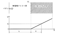
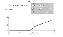
- the single stage reflectron is the most simplified multi-stage structure. An outline of the potential of the single stage reflectron is shown in FIG. 23 (see Non-Patent Document 1).
- the ion reflector has a uniform electric field (that is, the potential U is proportional to the distance X), and a grid electrode G through which ions can pass is disposed at the boundary between the non-electric field drift portion and the ion reflector.
- the time-of-flight spread is compensated to the first derivative of the energy, resulting in first order energy convergence (hereinafter simply referred to as first order convergence).
- first order convergence 2 ⁇ a
- first-order convergence the time-of-flight spread does not compensate for the second and higher order higher order derivatives of energy, so high mass resolution is obtained only for ions with a relatively small energy spread.
- a point at the depth a in the single stage reflectron is referred to as a primary convergence position.
- FIG. 24 is a potential schematic diagram of a dual stage reflectron.
- the dual-stage reflectron was originally developed by Mamyrin et al. (See Non-Patent Document 2).
- the ion reflector is composed of a two-stage uniform electric field.
- the boundary between the drift portion and the first stage uniform electric field (first stage) and the boundary between the first stage uniform electric field and the second stage uniform electric field (second stage) are both determined by the grid electrode G. It is partitioned. If the length of the first stage is sufficiently short and about 2/3 of the initial energy is lost in the first stage, the time-of-flight spread is compensated to the second derivative of energy, in other words, the second-order energy convergence. (Hereinafter, simply referred to as quadratic convergence) holds, so that high mass resolution can be obtained.
- Equation (2) shows that a and p satisfying the second-order convergence condition are uniquely determined when the lengths of b and c are determined.
- the spread of time of flight is compensated to the second derivative of the ion energy, so that a higher mass resolution can be obtained for ions having a relatively wide energy spread than the single stage reflectron. it can.
- a point at the depth a in the dual stage reflectron is referred to as a secondary convergence position.
- Patent Document 1 and Non-Patent Document 4 an ion reflector is used for the purpose of suppressing the spread of the flight time even when the non-electric field drift portion is connected to an ion reflector having a gradient electric field.
- the internal potential is the sum of a potential proportional to the distance X and a potential proportional to the square of the distance X.
- Patent Document 2 describes the configuration of a TOF-TOF apparatus for performing MS 2 analysis.
- the ion reflector in the subsequent stage has a non-uniform electric field type potential.
- the entire ion reflector is divided into two parts, a front-stage deceleration part and a rear-stage (non-uniform) correction potential part.
- the total flight time can be made completely independent of the initial energy of ions (above a certain threshold), that is, complete isochronism is theoretically possible. It is made clear.
- an ideal (one-dimensional) potential distribution on the central axis of the correction potential portion is determined by an integration formula, and an example in which the integration result is an analytical function form is given.
- Patent Document 3 has greatly contributed to the practical use of a reflectron having both high mass resolution and high energy convergence (ie, high sensitivity). This can be said to be a compromise between the multi-stage uniform electric field method and the non-uniform electric field method.
- an electric field that is almost constant is used until all of the first stage and the middle of the second stage.
- a correction electric potential portion is formed which is a uniform electric field portion and adopts a non-uniform electric field from there to the end, and correction is made so that the electric field strength on the central axis is substantially increased.
- the grid electrode is not used to avoid ion loss, and the electric field strength at the first stage is reduced to improve the convergence of the ion beam, and the mass resolution is sacrificed accordingly.
- the correction amount of the electric field intensity in the second stage is as small as 10% or less of the uniform electric field intensity.
- the equipotential surface of the gridless reflector is not flat but curved, ions passing through the trajectory away from the central axis. Is described that ion trajectory divergence occurs due to lens action.
- the ideal reflectron is expressed as “infinite high-order in terms of time-of-flight spread above a certain energy E 0 by using a potential distribution by a non-uniform electric field. It is defined that the energy can be converged up to the term. As will be described later, the following five basic conditions must be satisfied in order to put the ideal reflectron into practical use. ⁇ 1: Complete isochronism> Energy convergence is possible up to an infinite high-order term in terms of flight time. ⁇ 2: Suppression of beam divergence> Suppressing beam divergence at the reflector.
- ⁇ 3 Suppression of off-axis aberration> Suppressing temporal aberration with respect to the ion trajectory off the central axis, that is, off-axis aberration.
- ⁇ 4 Realization of potential> A practical ideal potential can be formed using a finite number of electrode groups.
- ⁇ 5 Non-uniform electric field tolerance before correction> As described later, a practical ideal potential can be realized even when a non-uniform electric field exists in the vicinity of the correction potential start part before correction.
- T (E) T (E 0 ) + (dT / dE) (EE ⁇ 0 ) + (1/2) (d 2 T / dE 2 ) ⁇ (EE ⁇ E 0 ) 2 + (1/6) (d 3 T / dE 3 ) (EE 0 ) 3 + ...
- Wiley-McLaren Wiley- McLaren
- McLaren Wiley-McLaren
- the Mamyrin solution uses a second-order convergence that cancels up to the second-order differential coefficient in the equation (5) by the dual-stage reflectron. Since the differential coefficients of the second order or higher in the former and the third or higher order of the differential coefficients remain in the latter without being canceled out, none of them is an ideal reflectron.
- ⁇ 2: Suppression of beam divergence> and ⁇ 3: Suppression of off-axis aberration> are also very important for practical use of an ideal reflectron.
- the causes of beam divergence and temporal aberration are both due to the fact that the non-uniform electric field in vacuum is divE ⁇ 0.
- the ion reflector acts as a concave lens, causing divergence of the ion trajectory, leading to a decrease in signal intensity.
- the former will be referred to as a divergence problem, and the latter as a time aberration due to off-axis.
- ⁇ 4: potential realization> is also important. This is because even if a correction potential formed inside the reflector in order to realize complete isochronism is theoretically obtained, it cannot always be realized as a three-dimensional potential distribution. In other words, even if a one-dimensional potential distribution having an ideal value on the central axis (hereinafter referred to as 1D-IDL) is found, a potential distribution (hereinafter referred to as 3D-SIM) simulating it in three dimensions. 3D-SIM is not guaranteed to be a practical approximation of 1D-IDL because there is an absolute constraint that it is a solution of the Laplace equation.
- the correction potential is analytically obtained on the premise that the electric field that is the base before correction is a uniform electric field in the vicinity of the correction potential start portion.
- the grid electrode installed at the boundary of the electric field, there is a disturbance of the electric field due to the seepage of the electric field, and it is clear from the examination of the present inventors that this drastically reduces isochronism. Became.
- the electric field non-uniformity is further increased, and the problem is further increased.
- ⁇ 1: complete isochronism> is achieved in, for example, Patent Document 4 and Non-Patent Document 7 (hereinafter referred to as “Koter et al.”). . That is, according to these documents, a general solution of the potential distribution of an ideal reflectron capable of infinitely high-order energy convergence has already been obtained. However, these documents are limited to only one dimension (the ions move on the central axis). With the techniques described in these documents, ⁇ 2: suppression of beam divergence> and ⁇ 3: axis There is no mention at all about how to satisfy the basic condition regarding the movement in three dimensions, such as “suppression of outlier aberration>. Therefore, an ideal reflectron that can achieve both high mass resolution and high sensitivity has not been put into practical use. In other words, it can be said that the current reflectron sacrifices at least one of mass resolution and sensitivity.
- Step 1 An ideal potential distribution in the correction potential portion is expressed as a general solution including design parameters (distance and voltage).
- Step 2 The general solution obtained in Step 1 is expanded with a half-integer power series of (U ⁇ E 0 ).
- Step 3 The design parameters are adjusted so that the expansion coefficients obtained in Step 2 are individually made zero.
- the Nth order convergence position when the position where the Nth order convergence is established (hereinafter simply referred to as the Nth order convergence position) does not exist originally, the curvature of the potential distribution is small. It is automatically derived that there is no specific solution.
- the Nth-order convergence position is defined in more detail, it is assumed that the total flight time is a function of energy, and an energy E is assumed such that the differential value from the first floor to the Nth floor is 0, and the potential value is equal to that. The position on the central axis.
- the Nth-order convergence position does not necessarily exist in an arbitrary design, but rather the range of design parameters in which the Nth-order convergence position does not exist. It is known that there are quite a few. In other words, depending on how the design parameters are taken, the case where the Nth-order convergence position does not exist originally can occur more frequently.
- Non-patent document 8 (hereinafter referred to as “Droshenko's document”) is a continuous study of the technology described in Koter et al., And is one-dimensional, similar to Koter et al. According to Koter et al., The entire ion flight path including the ion source (or ion acceleration part) is divided into the forward path (upstream part), the return path (downstream part), and the corrected potential reflection part, and the forward path having an arbitrary potential distribution. For the return path, a general integration formula that determines the ideal potential distribution of the correction potential reflecting portion for realizing isochronism is given.
- the present invention has been made to solve the above-mentioned problems, and an object of the present invention is to provide a reflectron that is the ideal limit. Specifically, it has no deviation from a uniform electric field that causes severe ion divergence, suppresses the effects of off-axis time aberrations, and is practically isochronous for ions passing through the central trajectory. Is a reflectron that satisfies the condition that More specifically, a three-dimensional ideal reflectron that satisfies all the basic conditions from ⁇ 1: perfect isochronism> to ⁇ 5: non-uniform electric field tolerance before correction> is provided. This is the object of the present invention.
- One object of the present invention is to obtain a practical potential distribution that satisfies isochronism in a wider energy range than the prior art and has a small potential distribution curvature even when there is no electric field drift space. . This is because if such a potential distribution is obtained, it is assumed that the device design and the adjustment of experimental parameters are easy.
- Another object of the present invention is to provide a reflectron that satisfies isochronism as a whole mass analysis system including an ion source, which is indispensable as a component of a mass spectrometer.
- This technique employed in the present invention not only finds a general solution of the ideal potential distribution shown in the above-mentioned Koter et al. Document, but also has a small potential distribution curvature and is practical (that is, ⁇ 2 above). : Suppression of beam divergence> to ⁇ 5: Non-uniform electric field tolerance before correction>) and a specific special solution can be obtained.
- Step 1 Setting of Base Potential
- a model that approximately satisfies isochronism is considered with reference to a multistage reflectron such as a Wiley-McLaren solution or a Mamilin solution.
- the potential distribution X A (U) of the model optimized in this way is an object to be improved by correction. In the following description, this is referred to as a base potential.
- Step 2 Superimposition of correction potential
- This sum potential X R (U) is a potential to be realized in real on the central axis, and in the following description, this is referred to as a real potential.
- the starting point at which the correction potential is superimposed is the primary convergence position in the Wiley-McLaren solution, the secondary convergence position in the Mamilyn solution, and the correction potential X C (U) is superimposed only on the back side of the reflector from this point. .
- Step 1 based on a well-known fact (the first and second derivatives can be made zero using only a uniform electric field, and the first and second convergence positions are uniquely determined)
- X C (U) an optimized correction potential
- This method is completely new in that the lower-order terms such as the first order and the second order in the above equation (5) are canceled by the Wiley-McLaren solution and the Mamilyn solution, and the remaining higher-order terms are canceled by the correction potential. It is based on technical thought.
- the steps 1 and 2 on the premise that the uniform electric field is the base potential due to the influence of the electric field leaking out through the grid electrode provided at the electric field boundary, and In the method described in Droshenko, it is difficult to avoid a reduction in isochronism. Further, in a gridless reflector that does not use a grid electrode, the electric field non-uniformity is further increased, and the problem is further increased. Therefore, as an improvement of the above method, the condition that the single-stage type or two or more multi-stage type reflectors consist only of a uniform electric field is removed, and the case where it consists of a non-uniform electric field is included. Then, the base potential X A (U) is not necessarily a potential due to a uniform electric field, but even in that case, the starting point at which the correction potential is superimposed is the Nth-order convergence position newly obtained by numerical calculation or the like.
- the time-of-flight mass spectrometer uses an ideal potential distribution obtained by the above-described novel technique, and provides an ion ejection unit that accelerates by applying constant energy to the ions to be analyzed.
- An ion reflector for reflecting and folding the ions ejected from the ion ejection part by the action of an electric field, an ion detector for detecting ions reflected by the ion reflector and exiting the ion reflector, and Reflector driving means for driving the ion reflector to form a reflected electric field inside the ion reflector, and a time-of-flight mass spectrometer comprising the reflector driving means,
- the coordinate along the central axis of the ion reflector is X
- the potential monotonously changes along the central axis of the ion reflector, and as a result, the inverse function X A (U)
- U A (X) By applying a voltage to the ion reflector so that a predetermined potential distribution U
- a front ion drift unit is provided between the ion ejection unit and the ion reflector to fly forward ions emitted from the ion ejection unit,
- the ion reflector then reflects the ions that have passed through the forward ion drift portion by the action of an electric field and folds them back, and is further reflected by the ion reflector between the ion reflector and the ion detector and exits the ion reflector.
- It can be set as the structure provided with the back ion drift part for making the ion which flew next fly in the opposite direction to the said front ion drift part.
- These ion drift portions can be electric field drift portions for allowing ions to fly freely.
- the front ion drift part and the rear ion drift part are not essential, and the ion ejection part and the ion reflector, and the ion reflector and the ion detector are not interposed between the drift part and the space, respectively. It is good also as a structure connected.
- the electric field that becomes the predetermined potential distribution X A (U) may be a uniform electric field at least in the vicinity of the coordinate X 0 .
- the electric field may be uniform not only in the vicinity of the coordinate X 0 but also over the entire ion reflector.
- a grid electrode is disposed in a hollow region of the ion reflector, and the ion reflector is divided into a plurality of stages by the grid electrode. it can.
- the ion reflector operates as a single stage type or a multistage type ion reflector having two or more stages.
- it can also be set as the gridless structure without a grid electrode in the hollow area
- the stage is divided by the grid electrode.
- the electric field does not become a uniform electric field at least near the boundary. (In other words, a non-uniform electric field).
- non-uniformity of the electric field is more remarkable when trying to realize a plurality of stages with a gridless structure.
- the predetermined potential distribution X A (U) may be due to a non-uniform electric field.
- the number of N is theoretically not limited, but in practice, the calculation of the Nth order convergence position becomes more difficult as N is increased. Also, N is about 1 or 2 from the point of cancellation of higher-order terms by the correction potential.
- N 1 near the boundary of the starting point starting from the primary convergence position inside the ion reflector ⁇ U (X) ⁇
- a correction potential proportional to E 0 ⁇ 2.5 may be superimposed.
- the ion ejection unit can take various configurations, for example, an orthogonal acceleration ion source, a MALDI ion source, or the like.
- an aperture or a slit for limiting the ion passage range may be provided between the ion ejection portion and the reflector in order to suppress the influence of off-axis aberration. Or you may give the function which restrict
- the ion drift part when the front ion drift part and the rear ion drift part are provided, the ion drift part often does not have an electric field, but an acceleration / deceleration part is provided in a part thereof. It may be.
- a converging lens for suppressing the influence of off-axis aberration may be installed in a part of the front ion drift part, or the ion emitting part itself may have the effect of the converging lens.
- the ion reflector can take various configurations.
- the ion reflector may include a plurality of thin electrodes arranged along the ion optical axis.
- the reflector driving means can be a voltage source that individually applies a predetermined DC voltage to the plurality of thin electrodes.
- a plurality of thin electrodes are connected to each resistor included in the resistor network, and a predetermined voltage is applied between both ends of the resistor network so that an appropriate voltage is applied to each thin electrode. You may be made to do.
- the ion reflector may include a resistor whose electric resistance is adjusted along the ion optical axis. When such a resistor is used, the potential can be continuously changed along the ion optical axis, so that a more ideal potential can be formed compared to the case where a plurality of thin electrodes are used. Is possible.
- the ion reflector may be configured using a printed circuit board or a substrate formed by a fine precision processing technique. If a plurality of electrodes are formed on a printed circuit board or a microfabricated substrate by etching or the like, the electrode position accuracy can be achieved at a lower price than when a plurality of thin electrodes are used. Processing is possible with a precision of several tens of microns for printed circuit boards and several micron to submicron for microfabricated boards.
- the time-of-flight mass spectrometer installs not only a TOFMS composed of a single ion reflector but also a plurality of ion reflectors so as to reflect ions a plurality of times between the plurality of ion reflectors.
- a multi-reflection time-of-flight mass spectrometer wherein at least one of the plurality of ion reflectors includes the ion reflector in which a predetermined correction potential X C (U) is superimposed on a predetermined potential X A (U). It can also be set as the structure which is. According to this configuration, the flight distance can be made very long, which is particularly effective for improving the mass resolution.
- time-of-flight mass spectrometer of the present invention high energy convergence is obtained for ions having a wider energy spread than before by using a true ideal reflectron that could not be realized in the past. It is done. For this reason, for example, ions are spread and distributed over a wide spatial range during ion ejection inside the ion source (ion ejection unit), and high mass resolution can be achieved even when there is a large variation in applied energy. . Furthermore, since divergence of ions inside the ion reflector can be prevented, it contributes to improvement of ion detection sensitivity as a result.
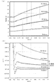
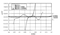
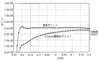
- FIG. 6 is a diagram showing a calculation result (3D-SIM) (b) of a relationship between relative energy spread ⁇ U / U and relative time spread ⁇ T / T.
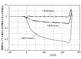
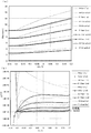
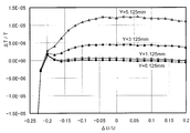
- FIG. 6 is a diagram showing an error between an ideal real potential (1D-IDL) and a corresponding three-dimensional approximate potential distribution (3D-SIM) for a single-stage reflectron.
- FIG. 18 is a diagram showing a simulation result (3D-SIM) when the grid electrode is an ideal grid electrode in the configuration shown in FIG. 17.
- FIG. 18 is a diagram showing a simulation result (3D-SIM) when a realistic grid electrode is used in the configuration shown in FIG. 17 and an electric field exudation at the grid electrode is taken into consideration.
- the ideal system here is the following situation.
- the component of the apparatus does not include an ion source (ion ejection unit), and a group of ions that have started flying with different initial energies from a certain point in the no-field drift unit is reflected by the reflector and is detected. Shall be reached.
- an ideal grid electrode in which no electric field oozes out and no ion deflection occurs in the grid electrode that partitions the electric field.
- the guard ring electrode (electrode thickness 0.2 [mm]) used for the simulation has a circular opening (inner diameter ⁇ 40 [mm]), the electrode interval is 5 [mm], and there is no limit on the number of electrodes. To do.
- the electric field inside the ion reflector is assumed to be a uniform electric field.
- this inverse function X * (U) is also simply referred to as a potential.
- the base potential X A (U) represents the following electric field (6) It is expressed by the linear equation.
- X A (U) L + (a / U a ) U (6)
- this equation (6) is effective when X A (U) ⁇ 0, and X A (U) ⁇ 0 is naturally determined from left-right symmetry.
- T S (E) 4 (T free (E) + T ref-a (E)) (7-2)
- T free (E) L / ⁇ (2E) (7-3)
- T ref-a (E) a ⁇ (2E) (7-4)
- T free (E) is the time required for ions to pass through the no-field drift part
- T ref-a (E) is the time required for ions to fly in the uniform electric field of the ion reflector.
- a solution satisfying complete isochronism is searched by superimposing a correction potential on the base potential X A (U) by the uniform electric field expressed by the above formula (6).
- isochronism can be realized only by adding a small correction potential X C (U) to the potential X A (U) by a uniform electric field in the range of
- Non-Patent Document 6 describes an inverse function of a potential distribution U (X) that gives such a flight time from a flight time T (E) for an arbitrary round, that is, the above-described real potential X R (U). A method of back calculation is described.
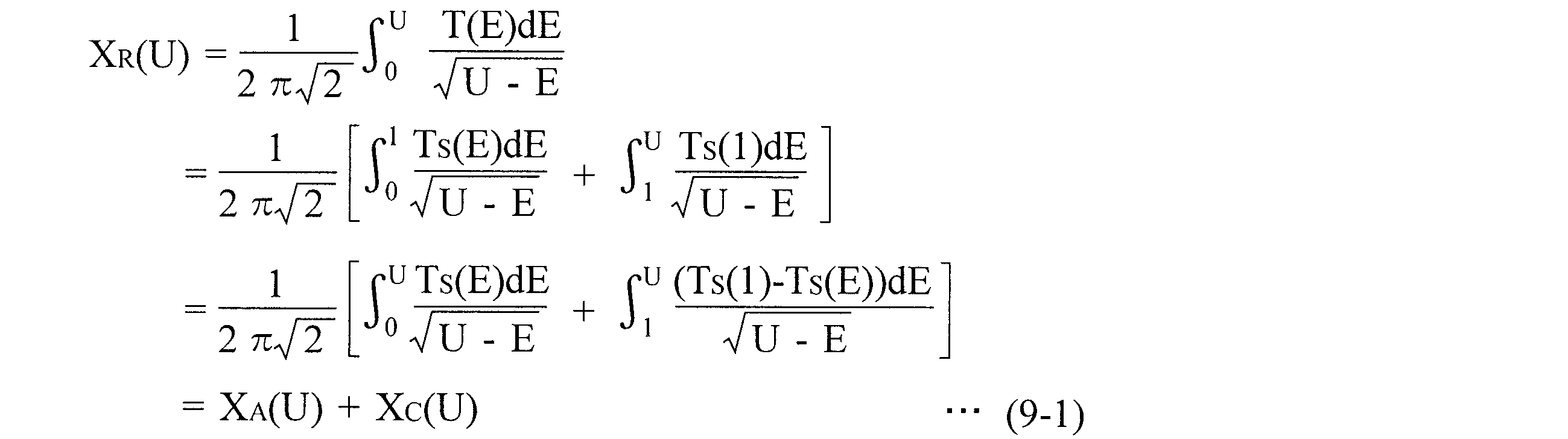
- Non-Patent Document 6 (12.2) is re-expressed as the following (8). If this equation (8) is used, it can be rewritten as the following equation (9-1), and it can be seen that the ideal potential distribution is uniquely determined by the integral calculation.
- the base potential X A (U) and the correction potential X C (U) by the uniform electric field are the following equations (9-2) and (9-3).
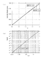
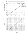
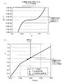
- the result (1D-IDL) of the real potential X R (U) obtained by the calculation is shown in FIG.
- FIG. 3B shows the result (1D-IDL) of the logarithm plot of the correction potential X C (U) with respect to U ⁇ 1.
- the correction potential X C (U) is almost linear and small U ⁇ 1. It can be seen that X C (U) ⁇ (U-1) 2.5 in the range.
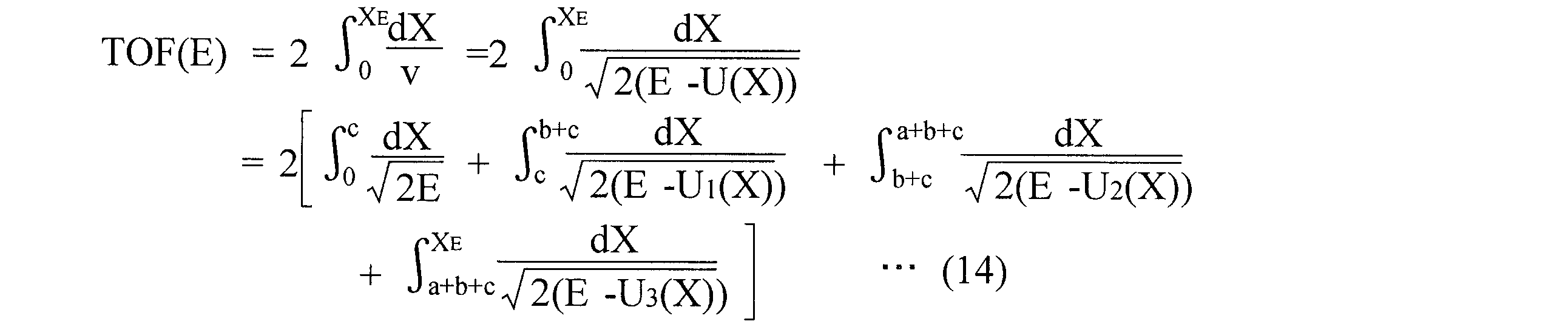
- Flight time TOF (E) can be obtained from the following equation (10).
- X E is an X coordinate of an ion turning point (turning position)
- U 1 (X) and U 2 (X) are potential distributions at L ⁇ X ⁇ L + a and X ⁇ L + a, respectively.
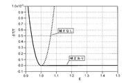
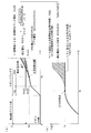
- FIG. 4 shows calculation results (1D-IDL) with and without the correction potential.
- the correction potential X C (U) it is understood that isochronism is fairly strictly established in the range of E ⁇ 1.
- Such loss of symmetry is not possible with a multi-stage reflectron and cannot be extended to the low energy side (U ⁇ 1), such as X C (U) ⁇ (U-1) 2.5. It is necessary to add a correct potential. In other words, a half-integer power is required to generate such an asymmetric state.
- the correction potential X C (U) near the correction potential start point is a half integer (2.5). Since it is approximated by a power, this function form always diverges the higher-order derivative with respect to the position. For this reason, it is impossible to strictly realize the potential distribution in the vacuum atmosphere. Moreover, since the correction potential start point is a point through which all ions of E ⁇ 1 pass, it is necessary to quantitatively grasp the influence. Therefore, it was verified by simulation (3D-SIM) whether practical isochronism can be obtained even with an approximate potential distribution using a limited number of guard ring electrode groups.
- L 829.123 [mm]
- the total length of the reflectron was 670 [mm].
- the size of one electrode was an inner diameter of 40 [mm] and the thickness was 0.2 [mm]
- 134 electrode plates were arranged at intervals of 5 [mm].
- the potential is corrected within a range of 5600 [V] or more so that ions having an energy spread of 7 [keV] ⁇ 20% can be converged.
- an optimum voltage was applied to each guard ring electrode so that an ideal real potential was formed on the central axis of the reflectron.
- FIG. 5A shows the calculation result (3D-SIM) of the relationship with U
- FIG. 6 shows an error between an ideal real potential (1D-IDL) and a corresponding three-dimensional potential distribution (3D-SIM) in a single stage reflectron.
- This off-axis time aberration is approximately proportional to the square of the displacement amount R, and in order to suppress the off-axis time aberration, it is necessary to use a spatial region near the central axis where the displacement amount R is small.
- the displacement amount R should be limited to about 3 [mm] in order to achieve the mass resolution of 50000 in the range of ⁇ 0.2 ⁇ ⁇ U / U ⁇ 0.2.
- mass resolution is sacrificed, a wider spatial spread of ions can be allowed. From these results, it was confirmed that practical isochronism can be obtained even with an approximate potential distribution using a finite number of guard ring electrodes.
- the single-stage reflectron described above requires a certain length of ion reflector, so the overall length is longer than that of the dual-stage reflectron described later, but the number of grid electrodes required is small. Therefore, there is an advantage that the ion loss due to the collision with the grid electrode is relatively small and the sensitivity can be easily increased.
- the second-order convergence condition in the dual-stage reflectron is also new as described below. To consider.
- T D (E) 4 (T free (E) + T ref-a (E) + T ref-b (E)) (12-2)
- T free (E) c / ⁇ (2E) (12-3)
- T ref-a (E) ⁇ a / (1-p) ⁇ ⁇ ⁇ 2 (Ep) ⁇ (12-4)
- T ref-b (E) (b / p) [ ⁇ (2E) ⁇ ⁇ 2 (Ep) ⁇ ] (12-5)
- T free (E) is the time for ions to pass through the no-field drift region
- T ref-a (E) is the ions flying in the second stage consisting of a uniform electric field.
- T ref-b (E) represents the time required to pass through the first stage consisting of a uniform electric field.
- the correction potential is superimposed on the base potential X A (U) in the range of
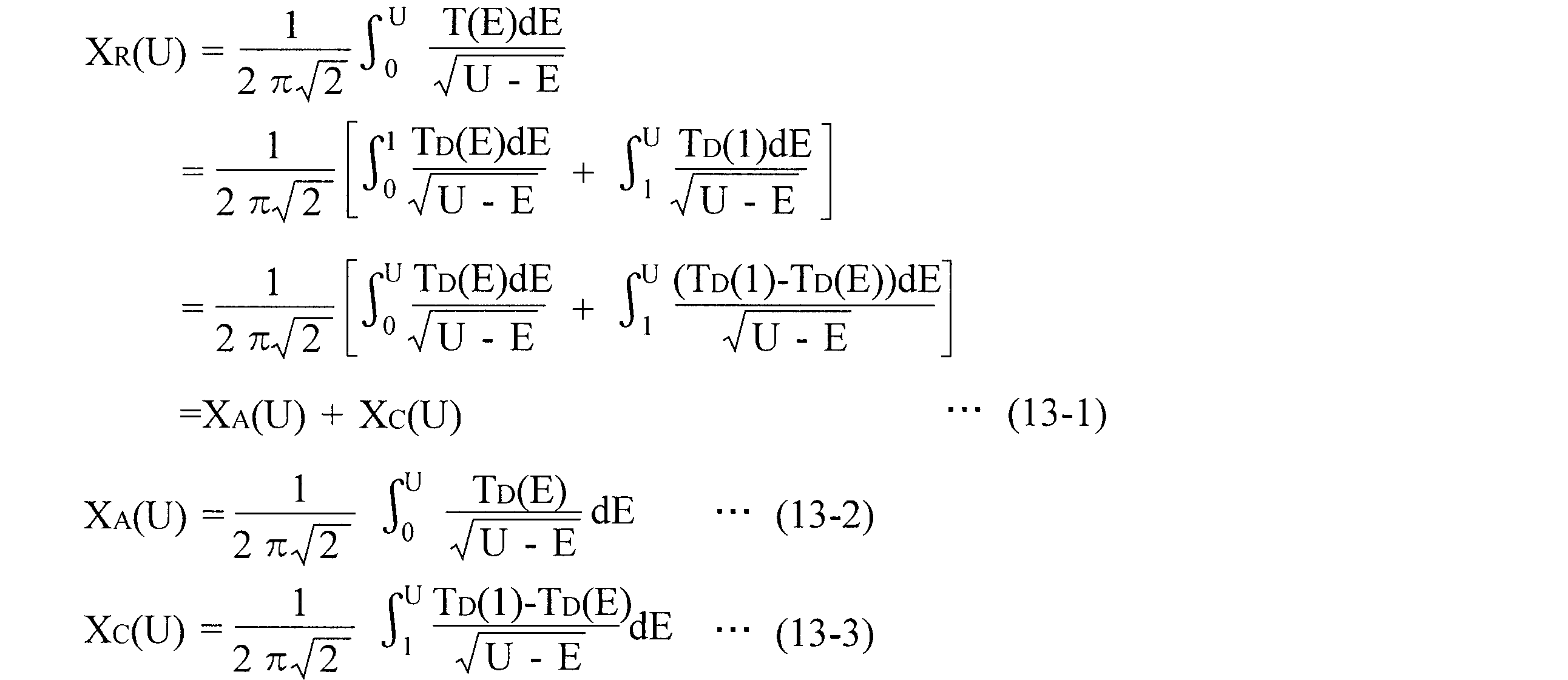
- the same relational expression as the expression (9) is established from the expression (8) as follows, regardless of the difference in the flight time T (E) for one lap.
- the base potential X A (U) represents a value obtained by extending the uniform electric field of the second stage to U> 1 in Equation (11), and the correction potential X C (U) represents a deviation from the uniform electric field. Represents.
- FIG. 9A shows the calculation result (1D-IDL) of the real potential X R (U).
- the base potential X A (U) is a uniform electric field when U ⁇ 1, and a small correction potential is added to the base potential X A (U) due to a uniform electric field of the same intensity when U ⁇ 1.
- X C (U) is added.
- FIG. 9B shows the result (1D-IDL) of the logarithmic plot of the correction potential X C (U) with U-1 as the horizontal axis.
- the correction potential X C (U) ⁇ (U ⁇ 1) 3.5 is obtained in a small range of U on a substantially straight line. This indicates that the correction amount is smaller than X C (U) ⁇ (U ⁇ 1) 2.5 of the Wiley-McLaren solution.
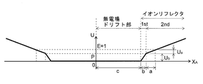
- FIG. 10A is a conceptual diagram showing a relationship between a base potential and a real potential due to a uniform electric field in a dual stage reflectron. That is, as viewed from the direction in which ions enter the ion reflector, the correction potential X C (U) is applied to the deeper side starting from the secondary convergence position.
- X E is the ion turning point (turning position)
- U 1 (X), U 2 (X), and U 3 (X) are c ⁇ X ⁇ b + c, b + c ⁇ X ⁇ a + b + c, and X ⁇ a + b + c, respectively.
- FIG. 11 shows the result (1D-IDL) of calculating the relative value ⁇ T / T of the deviation in flight time with respect to the initial energy in the case with and without the correction potential X C (U).
- Such a loss of symmetry is not possible with a multi-stage reflectron, and can be extended to the low energy side (U ⁇ 1) of X C (U) ⁇ (U-1) 3.5. It is necessary to add an impossible correction potential X C (U). In other words, a half integer, specifically, a power of 3.5 is required to generate such an asymmetric state.
- the number of grid electrodes required is two, so although the ion loss due to collision with the grid electrode increases compared to the single stage reflectron, the ion reflector is short. Therefore, there is an advantage that the total length is reduced. More importantly, since the correction potential amount is small, it is possible to further suppress the influence of the undesired ion divergence problem.
- the correction potential X c (U) near the correction potential start point is a half integer. Since it is approximated by a power of (3.5), a high-order differential coefficient related to the position of the ideal real potential X A (U) always diverges. Therefore, it is necessary to confirm whether or not such a real potential can be formed by practical hardware. Therefore, the inventor of the present application examined by simulation (3D-SIM) whether or not it is possible to form the ideal real potential with a practical number of guard ring electrodes.
- c 1400 [mm]
- b 30 [mm]
- the length of the second stage is 370 [mm].
- guard ring electrodes with an inner diameter of 40 [mm], a thickness of 0.2 [mm], and an interval of 5 [mm].
- the potential is corrected within a range of 5600 [V] or more so that ions having an energy spread of 7 [keV] ⁇ 20% can be converged.
- an optimum voltage was applied to each guard ring electrode so that an ideal potential was formed on the central axis of the reflectron.
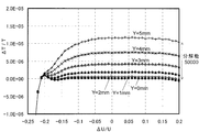
- FIG. 12 shows a simulation result (3D-SIM) of the relative time spread ⁇ T / T with respect to the relative energy spread ⁇ U / U when ions fly over the central axis of the reflectron.
- 3D-SIM simulation result
- the relative time spread ⁇ T / T is isochronous at a high level of the order of 10 minus 6 (center). On the axis) has been achieved. Accordingly, it was confirmed that the above method is effective even when a finite number of guard ring electrodes are used.
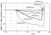
- the ions in the range of ⁇ U / U ⁇ 0.2, the ions cannot reach the correction potential portion and are reflected at the front portion from the secondary convergence position consisting of a uniform electric field. No divergence occurs. Divergence is seen in the range of -0.2 ⁇ ⁇ U / U ⁇ 0.2 where the ions are reflected at the correction potential part, but since the deviation from the uniform electric field is small, the equipotential surface is almost parallel and suppressed to a minimum Has been. The degree of divergence increases as the displacement amount R increases. It can be seen that the degree of divergence is suppressed in the dual stage reflectron compared to the single stage reflectron.
- FIG. 14 shows an error between an ideal real potential (1D-IDL) and a corresponding three-dimensional approximate potential distribution (3D-SIM) in the dual stage reflectron.
- ions in the range of ⁇ U / U ⁇ 0.2 cannot reach the correction potential portion, and are reflected at a portion before the secondary convergence position consisting of a uniform electric field. Therefore, there is no dependency of the flight time on the displacement amount R.
- the mass resolution decreases due to time aberration due to off-axis as the ion trajectory deviates from the central axis.
- This off-axis aberration is approximately proportional to the square of the displacement amount R, and it can be said that it is necessary to use a spatial region near the central axis with a small displacement amount R in order to suppress the off-axis aberration. Nevertheless, the effects of off-axis aberrations are small compared to single-stage reflectrons, and as long as the ion trajectory is limited to a range of deviation R ⁇ 10 [mm] from the central axis, TOFMS currently in practical use It can be confirmed by simulation that the upper limit of mass resolution of 40000 to 50000 can be cleared.
- the main cause of off-axis aberration is an error of the actual potential distribution from the ideal potential distribution.
- the potential distribution U (R, X) inside the reflector is given by the following equation (15).
- U (R, X) ⁇ (X) ⁇ A ⁇ R 2 ⁇ ′′ (X)
- ⁇ (X) is the potential on the central axis
- A is a constant determined by the opening shape of the guard ring electrode
- ⁇ ′′ (X) is the second derivative of ⁇ (X).
- ⁇ ′′ (X) becomes smaller as the real potential X R (U) that satisfies complete isochronism is closer to a uniform electric field, so that it can be said that this is a more preferable solution in practical use.
- the correction potential start point is set to the Nth-order convergence position, and the higher the order N, the closer to a uniform electric field, which is preferable in reducing off-axis aberrations.
- the opening shape of the guard ring electrode was a round hole shape.
- the opening shape is not limited thereto, and a guard ring electrode having a slit shape or a long hole shape should be used. Is also possible.
- a guard whose opening shape is a slit shape or a long hole shape It is more convenient to use a ring electrode because a wide space region capable of achieving high mass resolution can be secured in one direction. Even in this case, the same good performance as that of the guard ring electrode whose opening shape is a round hole shape can be achieved.
- the basic procedure of the present invention is to firstly define the apparatus configuration of a single stage type or multistage type reflectron.
- a reference model satisfying approximate isochronism is used, and a base potential X A (U) is formed inside the ion reflector to create an Nth-order convergence position.
- the non-uniform correction potential X C (U) is superimposed on the base potential X A (U), and the real potential X C ( U). Therefore, in the case of the single stage reflectron described above, the first-order differential coefficient is zero in the absence of the correction potential X C (U).
- the correction potential X C (U) is raised to a power of half integer (U ⁇ E 0 ) n + 1. / 2 is necessary. That is, by using the following equation (18) in which the correction potential X C (U) is expanded by a half-integer power series, the energy in the flight time T (E) for one round is corrected to the nth order ( That is, the differential coefficients up to the nth order can be made zero), and high isochronism can be realized for ions whose energy E is E ⁇ 1.
- X C (U) ⁇ a k (U ⁇ 1) k + 1/2 (18)
- the allowable range of the exponent of “half-integer power” or “N + 3/2” as used in this specification is a range of about 0.2, which is about twice of 0.1. In other words, it can be understood that “N + 1.5 ⁇ 0.2”, that is, a range of about N + 1.3 to N + 1.7.
- the distribution of the correction potential X C (U) is well expressed by the power of the half integer described above is limited to the range near the boundary that is the starting point of the correction potential.
- the correction potential X C (U) may be expressed by a power of a half integer in the range of 0 ⁇ U ⁇ 1 ⁇ 0.01. As the range becomes wider, the exponent deviates from the half integer value.
- the index is 3.48 in the range of 0 ⁇ U ⁇ 1 ⁇ 0.01, but when the range is expanded to 0 ⁇ U ⁇ 1 ⁇ 0.1, the index is 3. 30.
- the “near the boundary of the starting point” in this specification is 0 ⁇ U ⁇ 1 ⁇ 0. It is a spatial range that satisfies about one.
- the range of the “Nth order convergence position” will be described.
- a single-stage or multi-stage ion reflector having a base potential of only a uniform electric field before the correction potential X c (U) for realizing isochronism is superimposed is considered as a reference model.
- the mass resolution targeted for practical use is RSa
- the ion reflection space region in which the mass resolution RSa can be realized using the Nth-order convergence condition with this reflector is S
- this ion reflection space region S is the starting point of the correction potential superposition.
- the range of “Nth order convergence position” is as follows. As a specific example, a case where a quadratic convergence condition is used in a dual stage reflectron is illustrated.
- the ion emitting part such as the ion source exists only in the forward path of the ion flight path, and the forward and backward paths are compared, for example, the presence or absence of an ion beam optical element such as an ion lens or a deflector is different.
- an ion beam optical element such as an ion lens or a deflector
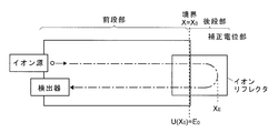
- the rear stage portion is provided with a correction potential portion in which some correction potential is superimposed on a uniform electric field so that the entire flight time from the ion source to the detection portion is kept constant.
- the rear stage portion is different from the front stage portion, and guarantees perfect symmetry between the forward path and the return path.
- T (E) is the total flight time
- T A-1 (E) is the flight time in the front stage that combines the forward and return paths
- T B (E is the flight time in the rear stage that combines the forward and return paths.
- T (E) T A-1 (E) + T B (E) (19-1)
- T B (E) ⁇ 0.
- the relationship between the flight time T B (E) in the rear stage and the potential distribution U B (E) in the correction potential part is expressed by the following equation (19-2).
- Equation (19-3) When both sides of equation (19-2) are multiplied by 1 / ⁇ ( ⁇ E) and energy E is integrated from E 0 to ⁇ , the potential distribution in the correction potential section as shown in the following equation (19-3): ⁇ X B ( ⁇ ) is derived.
- the potential distribution in the correction potential portion is not U B (X), but the base potential consisting of a uniform electric field in the vicinity of the boundary extends to the correction potential portion, and accordingly the time required for ions in the correction potential portion.
- T A-2 (E) is substituted for T B (E)
- the following equation (19-4) is obtained.
- ⁇ X A ( ⁇ ) is a potential distribution in which the base potential formed of a uniform electric field near the boundary extends to the correction potential portion.
- Equation (19-1) is used to derive the last equation.
- T A (E) T A-1 (E) + T A-2 (E), and this T A (E) is temporarily followed by a base potential consisting of a uniform electric field from the front stage to the rear stage. It is the total flight time when it is assumed. (19-6) from the equation, T (E 0) in the integral equation -T A deviation [Delta] X B (alpha) from a uniform electric field more (E) is less - ⁇ X A ( ⁇ ) can be easily be reduced Can understand.
- the Nth-order convergence position inside the ion reflector is calculated as a whole system including all such components, and the N It is proved for the case where the uniform electric field is used as the base potential that the complete isochronism of the entire system can be realized by superimposing a correction potential consisting of an appropriate nonuniform electric field in the space behind the next convergence position. That is why.
- This is in contrast to the technique described in Non-Patent Document 3 that has been widely used in the past, in which the ions emitted from the ion source are once converged for a time and the focused position is used as a virtual ion source for the reflectron. .
- the grid electrode is disposed at the boundary of each stage of the multi-stage reflectron.
- an ion reflector having a gridless structure is assumed, and the potential distribution and the Nth-order convergence are formed inside the grid reflector. If the position is obtained by numerical calculation, an ideal reflectron can be configured even in a configuration that does not use a grid electrode, as in the configuration that uses a grid electrode.
- the configuration not using the grid electrode has an advantage that there is no loss of ions due to collision with the grid electrode, which is advantageous for high sensitivity.
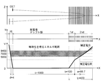
- FIG. 17 shows a schematic diagram of the electrode shape and the potential shape used in the simulation (3D-SIM).
- T ID (E) T is (E) + T free (E) + T ref-a (E) + T ref-b (E)
- T free (E) 2c / ⁇ (2E)
- T ref-a (E) ⁇ 2a / (1-p) ⁇ ⁇ ⁇ 2 (Ep) ⁇
- T ref-b (E) (2b / p) [ ⁇ (2E) ⁇ ⁇ 2 (Ep) ⁇ ]
- T is (E) is the time for ions to fly through the ion accelerator
- T free (E) is the time for ions to fly through the no-field drift region
- T ref-a (E) and T ref-b (E) Is the time for ions to fly through the second and first stages of the reflector, respectively.
- An ideal correction potential was calculated using equation (19), and an appropriate voltage was applied to each guard ring electrode so that an ideal real potential was formed on the central axis of the reflector.
- FIG. 18 shows a simulation result (3D-SIM) when the grid electrode is an ideal grid electrode (no electric field oozes and no ion deflection occurs).
- isochronism is greatly impaired when parallel wire grid electrodes are used, and high mass resolution cannot be achieved. This is because the secondary convergence condition has changed due to the leakage of the electric field at the grid electrode.
- FIG. 20 shows an ideal real potential V ideal at this time and a deviation ⁇ V from the ideal value of the corresponding approximate three-dimensional potential distribution (3D-SIM). It can be seen that the potential distribution formed varies greatly due to the seepage of the electric field through the grid electrode. Further, it is understood that the electric field oozes up to the vicinity of the correction potential start point (secondary convergence position), and the electric field is not uniform near the correction potential start point. This means that there is a limit in the prior art (Kota et al. And Droshenko) which assumes a uniform electric field in the vicinity of the correction potential start point when considering the reality.
- the Nth-order convergence position obtained by assuming a uniform electric field is the best starting point for minimizing the correction potential even for non-periodic motion, or is not important for periodic motion such as an ion source. Even when the components are included, if the Nth-order convergence position inside the ion reflector is calculated as the entire system including all such components, and the correction potential is superimposed in the back space from that position, the entire system will be The conclusion that the complete isochronism can be realized also holds when a non-uniform electric field is used as the base potential.
- FIG. 21 shows a simulation result (3D-SIM) in the case where the electric field oozes out at the grid electrode. Comparing the results of FIG. 21 with FIGS. 18 and 19, it can be seen that a high level of isochronism is realized again by recalculation in consideration of the leakage of the electric field.
- the first method is to reduce the secondary differential ⁇ ′′ (X) of the potential on the central axis, and as described above, this is achieved by using a potential distribution that is as close to a uniform electric field as possible. .
- the second method is to reduce the spatial extent of the ion beam near the correction potential start point.
- an aperture or a slit for limiting the ion beam spread is provided between the reflector and the ion source, or the electrode of the reflector or the ion source has a function for limiting the ion beam spread. This removes (shields) ions incident at a large distance from the central axis.
- the aperture diameter and slit width may be adjusted according to the required mass resolution and sensitivity. For example, when high mass resolution is desired, the aperture diameter and slit width are reduced. This reduces the amount of ions and sacrifices signal strength, but can increase mass resolution using only components with small temporal aberrations.
- the space between the ion source (orthogonal acceleration unit) and the reflector is reduced so that the spatial spread of the ion beam is reduced near the correction potential start point. It is conceivable to install a focusing lens on the ion path. Alternatively, the ion source itself may have a converging lens effect. By adjusting the voltage applied to these converging lenses, the spatial spread of ions incident on the reflector can be reduced, and the divergence and temporal aberration of the ion beam can be reduced.
- Equation (19-3) is central to the handling of non-periodic motion.
- This equation (19-3) is the most general method of deriving the potential distribution ⁇ X B (U) in an area from the flight time T B (E) in an arbitrary area (referred to herein as the “rear stage”). It is a formula.
- T B (E) is only defined as the time of flight at the rear stage, and only the condition that the total flight time is strictly constant T (E 0 ) is imposed. .
- T A-1 (E) T (E 0 ) ⁇ T A-1 (E).
- T A-1 (E) can only be physically positive as a function of energy E.
- T B (E) positive (19-3) ) Is also true.
- E 0 is replaced with 0
- X 0 is replaced with 0, that is, the energy and the origin of coordinates are translated to assume a potential distribution that is symmetric between X ⁇ 0 and X> 0.
- the formula (8) important in periodic motion can be obtained again as a special example.
- equation (19-3) when comparing the equation (19-3) with the equation (8) which is the corresponding general equation for the case of periodic motion, both are 1 / ⁇ (constant ⁇ E). It is a definite integral of energy that has an integral kernel. Therefore, equation (19-3) also satisfies the superposition principle. That is, the potential distribution at the rear stage is ⁇ X B1 ( ⁇ ) with respect to the flight time T B1 (E) at the rear stage, and the potential distribution at the rear stage with respect to the flight time T B2 (E) at the rear stage.
- the deviation ⁇ X B ( ⁇ ) - ⁇ X A ( ⁇ ) from the uniform electric field, which is the base potential, for non-periodic motion, that is, the correction potential is a half integer power expansion. Re-arrange what you can express. This is because the above ⁇ 5: non-uniform electric field tolerance before correction> can be derived.
- the above equation (19-5) assumes two cases. That is, one is a case where the potential distribution ⁇ X B ( ⁇ ) corresponds to the flight time T B (E) at the rear stage part to satisfy the complete isochronism as a whole. The other is a case where the same uniform electric field ⁇ X A ( ⁇ ) is continuously used from the front stage to the rear stage, and the flight time T A-2 (E) at the rear stage can be obtained.
- the difference in potential distribution with respect to the difference ⁇ T B (E) -T A-2 (E) ⁇ in the flight time at the rear stage, that is, the base potential is one. It can be concluded that the deviation from the electric field is ⁇ X B ( ⁇ ) ⁇ X A ( ⁇ ) ⁇ .
- Equation (19-7) is a method often used in the multistage reflectron for the difference in total flight time T (E 0 ) ⁇ T A (E), that is, Taylor expansion in the vicinity of energy E 0. , T (E 0 ) ⁇ T A (E) is expressed as the sum of the integer power expansion terms of (E 0 ⁇ E).
- equation (19-7) is correct when the Taylor expansion holds for the total flight time difference T (E 0 ) ⁇ T A (E), but this constraint is that ⁇ X A ( ⁇ ) is the correction potential. If the function is such that it is smoothly connected before and after the start point (that is, an infinite-order higher-order derivative is possible), it should be possible even if it is not a uniform electric field. Actually, this constraint condition is automatically established when a potential distribution formed in a vacuum region using a thin plate opening electrode as a guard ring electrode is set as a base potential.
- both the base potential X A (U) and the correction potential X C (U) may be based on a non-uniform electric field.
- the present invention can be applied even when a grid electrode is not used.
- the base potential X A (U) is drawn as a uniform electric field, but the base potential X A (U) may be a non-uniform electric field.
- the total flight time T (E) for energy E is examined. This is the “total flight time due to the real potential” indicated by a solid line in FIG. When E ⁇ E 0 , the flight time is ideally constant.
- the total flight time T D (E) based on the base potential at E ⁇ E 0 is determined by extrapolation from the function form at E ⁇ E 0 .
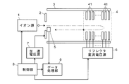
- FIG. 22 is a schematic configuration diagram of the TOFMS of this embodiment.
- ions derived from a sample generated by an ion source (corresponding to an ion ejection part in the present invention) 1 are given initial energy by an electric field formed by a voltage applied from the acceleration voltage source 7 to the acceleration electrode 2. And put into the flight space formed in the flight tube 3.
- an ion reflector 4 composed of a plurality of guard ring electrodes 41 arranged along the ion optical axis is installed, and each ion is reflected by an electric field formed by the ion reflector 4.
- the ions that are reflected and returned reach the detector 5, and the detector 5 outputs a detection signal corresponding to the amount of ions that have reached.
- a predetermined DC voltage is applied to each guard ring electrode 41 constituting the ion reflector 4 from a reflector DC voltage source (corresponding to the reflector driving means in the present invention) 6, whereby a predetermined DC voltage is applied to the internal space of the ion reflector 4.
- An electrostatic field (DC electric field) having a potential distribution is formed.
- the control unit 8 controls the ion source 1, the acceleration voltage source 7, the reflector DC voltage source 6, and the like.
- the data processing unit 9 obtains ion acceleration timing information, that is, flight departure time information from the control unit 8, and uses this as a reference to measure the flight time based on the detection signal of each ion.
- a mass spectrum is created in terms of mass to charge ratio m / z.
- the ion source 1 can be a MALDI ion source, for example.
- an atmospheric pressure ion source such as ESI or APCI may be used as the ion source
- EI or CI may be used as the ion source.
- an ion trap may be provided instead of the ion source 1 in FIG. 22, and ions may be ejected toward the flight tube 3 after the ions are once trapped in the ion trap.
- ions extracted from the ion source 1 may be accelerated by an accelerating electric field in a direction orthogonal to the ion extraction direction and introduced into the flight tube 3.
- the guard ring electrode 41 is set by setting the DC voltages V 1 , V 2 ,..., V n applied from the reflector DC voltage source 6 to each guard ring electrode 41 to predetermined values calculated in advance.
- V 1 , V 2 ,..., V n applied from the reflector DC voltage source 6 to each guard ring electrode 41 to predetermined values calculated in advance.
- the voltage to be applied to each guard ring electrode 41 of the ion reflector 4 and the potential distribution formed thereby can be obtained by simulation calculation. Therefore, if a desired potential distribution is determined as described above, a voltage value that realizes this can be obtained in advance (at the device design stage) by calculation.
- each guard ring electrode 41 constituting the ion reflector 4 only needs to have a structure surrounding one space as a whole, and the specific form has a degree of freedom. That is, as described above, when viewed from the central axis C of the ion reflector 4, the opening may not be circular, but may be oval, square, polygonal, slit, or the like, or one guard ring electrode. May be constituted by an electrode divided into a plurality of parts.
- each guard ring electrode 41 may be divided by resistance and applied to each guard ring electrode 41.
- the voltage applied to each guard ring electrode 41 can be adjusted by adjusting the resistance value of the network resistance for resistance division.
- the electrode itself may be a resistor having a cylindrical shape, for example, and the electric resistance may be adjusted along the ion optical axis so that the potential as described above can be formed inside.
- the reflector may be manufactured by drawing an electrode group on the printed board by etching or the like and forming a reflected electric field in a space surrounded by the plurality of printed boards.
- the ions may be incident substantially parallel to the central axis C so that the forward and backward paths of the ions are substantially on the same line.
- ions may be incident with a predetermined angle with respect to the central axis C so that the forward and backward paths of ions do not overlap.
- the TOFMS according to the present invention includes components that do not have periodic motion, complete isochronism can be realized by appropriately setting the electric field by the ion reflector.
- an electric field or a magnetic field for converging the ions between the ion reflector 4 and the ion source 1 or the detector 5 in the space in the flight tube 3 that is, no electric field drift part.
- an ion optical element such as a deflector for bending the ion trajectory.
- the ions are detected after reciprocating flight using the characteristic ion reflector described above, but this is not a simple reflection type configuration.
- a TOFMS having a multiple reflection type configuration in which the ion reflectors described above with the sandwiched therebetween are installed oppositely and ions are reciprocated a plurality of times between the ion reflectors may be used.
- the correction potential start point is set to the secondary convergence position using the secondary convergence condition.
- the primary convergence condition in the dual stage reflectron it is possible to set the correction potential start point as the primary convergence position.
- the multi-stage reflector is described as a reference model, but the TOFMS according to the present invention does not depend on the shape of the reflector at all, such as the number of stages and the presence or absence of grid electrodes. That is, the characteristics of the TOFMS according to the present invention defined by the claims of the present application can be organized as follows.
- a virtual reflectron serving as a base that approximately satisfies isochronism based on the prior art is considered.
- the base reflectron satisfies the following three conditions.
- the shape of the reflector does not matter at all, such as the number of stages and the presence or absence of grid electrodes.
- the reflector is hollow and changes monotonically to reflect ions (increases monotonically when the analysis target is positive ions, and decreases monotonically when the analysis target is negative ions). It does not matter whether the gradient potential is due to a uniform electric field or a non-uniform electric field.
- the first convergence condition is used for the Wiley-McLaren solution
- the second convergence condition is used for the Mamilyn solution.
- isochronism can be realized for ions reflected in a region deeper than the correction potential start point (Nth-order convergence position), and ion beam divergence and off-axis aberrations can be minimized.
- the potential is smoothly connected before and after the correction potential start point. As mentioned above, this is also applicable when dealing with non-periodic movements involving an ion source.
Landscapes
- Chemical & Material Sciences (AREA)
- Analytical Chemistry (AREA)
- Physics & Mathematics (AREA)
- Life Sciences & Earth Sciences (AREA)
- Electrochemistry (AREA)
- Health & Medical Sciences (AREA)
- Chemical Kinetics & Catalysis (AREA)
- Biochemistry (AREA)
- General Health & Medical Sciences (AREA)
- General Physics & Mathematics (AREA)
- Immunology (AREA)
- Pathology (AREA)
- Optics & Photonics (AREA)
- Other Investigation Or Analysis Of Materials By Electrical Means (AREA)
- Electron Tubes For Measurement (AREA)
Abstract
Description
L=2・a …(1)
しかしながら、1次収束では、飛行時間の広がりはエネルギについて2次以上の高次微分が補償されないため、高い質量分解能が得られるのは比較的小さなエネルギ広がりを持つイオンに対してのみである。なお、以下の説明では、シングルステージ式リフレクトロンにおいて深さaとなる点を1次収束位置と呼ぶこととする。
a=[(c-2b)/2(b+c)]・{b+[(√3)・(c-2b)3/2/9√c]}
p=2(b+c)/3c …(2)
ここでaは第2ステージへのイオン侵入深さ、bは第1ステージの長さ、cは無電場ドリフト部の長さ、pは第1ステージで失われるイオンエネルギの割合である。(2)式は、b、cの各長さが決まると2次収束条件を満たすaとpとが一意に決まることを示している。このデュアルステージ式リフレクトロンでは飛行時間の広がりがイオンエネルギの2次微分まで補償されるので、上記シングルステージ式リフレクトロンよりも比較的広いエネルギ広がりを持つイオンに対して高い質量分解能を得ることができる。なお、以下の説明では、デュアルステージ式リフレクトロンにおいて深さaとなる点を2次収束位置と呼ぶこととする。
U=(1/2)・k・X2 …(3)
TOF=π√(m/k) …(4)
ここで、mはイオンの質量、kは定数である。
即ち、飛行時間はイオンの初期エネルギに依存せず、厳密に等時性が成り立つ。しかしながら、TOFMSとしては(3)式の調和関数のように、無電場ドリフト部が全く存在しないような電位分布は実用的にはかなり深刻な欠点である。何故なら、無電場ドリフト部が全く存在しない場合、イオン源及び検出器をポテンシャルの底以外に配置することができず、装置設計上の制約が大きすぎるからである。そこで、この欠点を解消するため、特許文献1及び非特許文献4では、無電場ドリフト部を傾斜電場を持つイオンリフレクタと連結した場合にも飛行時間の広がりを抑制することを目的として、イオンリフレクタ内部のポテンシャルを距離Xに比例するポテンシャルと距離Xの2乗に比例するポテンシャルとの和としている。これにより、比較的広いエネルギ範囲に亘って或る程度のエネルギ収束性が確保される。その反面、厳密な等時性は崩れてしまうことになり、質量分解能の向上には限界がある。
<1:完全等時性>飛行時間について無限の高次の項までエネルギ収束が可能である。
<2:ビーム発散の抑制>リフレクタにおけるビームの発散を抑えること。
<3:軸外れ収差の抑制>中心軸を外したイオン軌道に対する時間収差、即ち、軸外れ収差を抑えること。
<4:電位の実現性>有限枚数の電極群を用いて、実用的な理想電位を形成できること。
<5:補正前の非一様電場許容性>後述するように、補正前に補正電位開始部付近に非一様電場が存在した場合であっても、実用的な理想電位を実現できること。
T(E)=T(E0)+(dT/dE)(E-E0)+(1/2)(d2T/dE2)・(E-E0)2+(1/6)(d3T/dE3)(E-E0)3+… …(5)
前述したように、一様電場によるポテンシャルを用い、シングルステージ式リフレクトロンで上記(5)式中の1次の微分係数までを打ち消すような1次収束を利用するのがワイリー・マクラーレン(Wiley-McLaren)解である。また、デュアルステージ式リフレクトロンにより上記(5)式中の2次の微分係数までを打ち消すような2次収束を利用するのがマミリン(Mamyrin)解である。前者では2次以上の、後者では3次以上の微分係数は打ち消されずに残るため、いずれも理想リフレクトロンとはいえない。
[ステップ1]補正電位部での理想的な電位分布を、設計パラメータ(距離や電圧)を含んだ一般解として表す。
[ステップ2]ステップ1で得られた一般解を(U-E0)の半整数べき級数で展開する。
[ステップ3]ステップ2で得られる展開係数を個別にゼロにするように設計パラメータを調整する。
[ステップ1:ベース電位の設定]ワイリー・マクラーレン解やマミリン解のようなマルチステージ式リフレクトロンなどを参考にして、近似的に等時性を満たすモデルを考える。具体的には、1次収束や2次収束などが達成されるように(即ち、dT/dE=0、d2T/dE2=0などとなるように)設計パラメータを調整する(1次収束位置や2次収束位置などを計算する)。このように最適化されたモデルの電位分布XA(U)は補正を加えて改良する対象であり、以下の説明ではこれをベース電位と称する。
[ステップ2:補正電位の重畳]ステップ1において設定したベース電位XA(U)に適切に算出した補正電位XC(U)を重畳して、和の電位XR(U)=XA(U)+XC(U)が<1:完全等時性>を満たすようにする。この和の電位XR(U)こそが中心軸上にリアルに実現されるべき電位であって、以下の説明ではこれをリアル電位と称する。ここで補正電位を重畳させる始点は、ワイリー・マクラーレン解における1次収束位置、マミリン解における2次収束位置などであって、この点よりリフレクタ奥側だけに補正電位XC(U)を重畳する。
前記イオンリフレクタの中心軸に沿った座標をXとしたとき、該イオンリフレクタの中心軸に沿って、該イオンリフレクタの全体に亘り電位が単調に変化し、その結果、逆関数XA(U)も一意的に得られる所定の電位分布UA(X)が該イオンリフレクタの中空領域に形成されるように該イオンリフレクタに電圧を印加することで、該イオンリフレクタ内部の座標X0で電位E0である位置にN次収束位置を形成するとともに、
座標X0であるN次収束位置を始点とする奥側の空間において、前記座標X0の近傍では{U(X)-E0}N+3/2に比例する式で近似でき、且つ前記座標X0から奥側において滑らかな関数となる所定の補正電位XC(U)を、前記所定の電位XA(U)に重畳させるように、前記イオンリフレクタに電圧を印加することを特徴としている。
まず、本発明に係るTOFMSにおいて特徴的なイオンリフレクタにおけるポテンシャルの設計手法を理想系に適用した場合について詳述する。ここでいう理想系とは、以下の状況である。
(1)装置の構成要素にはイオン源(イオン射出部)を含めず、無電場ドリフト部内の或る点から、異なる初期エネルギを持って飛行を開始したイオン群がリフレクタで反射されて検出器に到達するものとする。
(2)シミュレーションでは、電場を仕切るグリッド電極において電場の染み出しが無く、イオンの偏向も起こらない理想グリッド電極を用いるものとする。
(3)シミュレーションに用いるガードリング電極(電極厚み0.2[mm])は円形開口(内径φ40[mm])を有し、電極間隔は5[mm]で電極枚数に制限を設けないものとする。
(4)イオンリフレクタ内部での電場は一様電場であるとする。
以下、本発明に係るTOFMSのイオンリフレクタの設計手法を、シングルステージ式リフレクトロンとデュアルステージ式リフレクトロンの二つの具体例に沿って順に説明する。
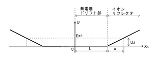
まず、1段の一様電場を有するシングルステージ式リフレクトロンのモデルについて、前述のベース電位XA(U)や補正電位XC(U)の算出方法を詳しく述べる。後の考察のため、図23に示した電位分布を座標原点X=0に関して左右対称とした、図1に示すようなベース電位XA(U)を想定し、この電位分布内でのイオンの周期運動を考える。(ここでUは電位値、X*は中心軸に沿った座標、*は区別のための任意の下付文字、をそれぞれ表すものとすると、X*(U)は通常では電位分布の逆関数を意味するが、これ以降はこの逆関数X*(U)も単に電位と呼ぶことにする。)具体的には、ベース電位XA(U)は一様な電場を表す次の(6)式の直線式で表される。
XA(U)=L+(a/Ua)U …(6)
但し、この(6)式はXA(U)≧0において有効であって、XA(U)<0については左右対称性から自ずと決まる。
TS(E)=4{[L/√(2E/m)]+(a/Ua)√(2mE)} …(7-1)
質量m=1、エネルギUa=1を基準として(7-1)式を簡略化すると以下の式が得られる。
TS(E)=4(Tfree(E)+Tref-a(E)) …(7-2)
Tfree(E)=L/√(2E) …(7-3)
Tref-a(E)=a√(2E) …(7-4)
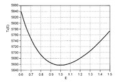
ここで、Tfree(E)は無電場ドリフト部をイオンが通過する時間、Tref-a(E)はイオンリフレクタの一様電場中をイオンが飛行するのに要する時間であって、1次収束の条件、つまり(dTS/dE)E=1=0のときによく知られた上述の(1)式が得られる。計算例として、L=1000[mm]としたときのエネルギEと1周分の飛行時間TS(E)との関係を図2に示す。エネルギE=1で1次の微分係数がゼロ(TS(E)が極小)になっており、1次の補正((5)式における1次の項の打ち消し)がなされていることが確認できる。ここまでは従来技術であるワイリー・マクラーレン解そのものである。


TS(1)-TS(E)=-(dTS/dE)E=1(E-1)-{1/(2!)}(d2TS/dE2)E=1(E-1)2-……-{1/(n!)}(dnTS/dEn)E=1(E-1)n-… …(9-4)

次に、本発明に係るTOFMSの設計手法を、2段の一様電場を備えるデュアルステージ式リフレクトロンに適用した例を説明する。前述のシングルステージ式リフレクトロンと同様に、ベース電位XA(U)は図7に示す通り、X=0に関して左右対称な形状(図24に示したポテンシャルをX=0に関して左右対称に展開した形状)である。具体的には一様電場を持つ二つの領域をつないだ電位分布として、次の(11)式を考える。
XA(U)=c+b(U/Ub) (但し0≦U≦Ubである場合)
XA(U)=c+b+a{(U-Ub)/Ua} (但しUb≦Uである場合) …(11)
TD(E)=4[c/√(2E/m)+(b/Ub)[√(2mE)-√(2m(E-Ub))]+(a/Ua)√{2m(E-Ub)}] …(12-1)
ここで質量m=1、エネルギUa+Ub=1を基準とし、Ub=pとして(12-1)式を簡略化すると次の各式が得られる。
TD(E)=4(Tfree(E)+Tref-a(E)+Tref-b(E)) …(12-2)
Tfree(E)=c/√(2E) …(12-3)
Tref-a(E)={a/(1-p)}√{2(E-p)} …(12-4)
Tref-b(E)=(b/p)[√(2E)-√{2(E-p)}] …(12-5)
ここではシングルステージ式リフレクトロンと同様に、Tfree(E)は無電場ドリフト領域をイオンが通過する時間、Tref-a(E)は一様電場からなる第2ステージ中をイオンが飛行するのに要する時間、Tref-b(E)は一様電場からなる第1ステージを通過するのに要する時間、を表している。ここで、2次の収束条件である(dTD/dE)E=1=0及び(d2TD/dE2)E=1=0を課すと、上述した(2)式の条件が得られる。E≦pの条件の下ではイオンは第1ステージで反射されるので、全エネルギ領域での1周分の飛行時間T(E)は以下の(12-6)式の通りになる。
TD(E)=4{Tfree(E)+(b/p)√(2E)} (但し0≦E≦pである場合)
TD(E)=4{Tfree(E)+Tref-a(E)+Tref-b(E)} (但しp≦Eである場合) …(12-6)
U(R,X)=Φ(X)-A・R2Φ”(X) …(15)
ここでΦ(X)は中心軸上での電位、Aはガードリング電極の開口形状で決まる定数、Φ”(X)はΦ(X)の2次微分である。(15)式から、軸外れ収差の影響を抑える方法として、変位量Rを小さくする、電位の2次微分Φ”(X)を小さくする、の二つを採り得ることが分かる。したがって、完全等時性を満たすようなリアル電位XR(U)が一様電場に近いほどΦ”(X)は小さくなるので、実用的にもより好ましい解であるといえる。つまり、マルチステージ式リフレクトロンで、補正電位の開始点をN次収束位置とし、その次数Nを大きくするほど一様電場に近くなるので、軸外れ収差を小さくする上で好ましい。
次に、上記実施例において補正電位関数XC(U)に2.5乗、3.5乗等の半整数のべき乗が出てきた理由について説明する。ここで基礎となるのは、リアル電位XR(U)と1周分の飛行時間T(E)との間で成り立つ重ね合わせの原理である。
上記(8)式が意味するところは、関数XR(U)と関数T(E)とが線形な積分変換で結ばれていることにより、解には重ね合わせの原理が成り立つということである。即ち、XR1(U)に対する1周分の飛行時間をT1(E)、XR2(U)に対する1周分の飛行時間をT2(E)とすると、XR1(U)+XR2(U)という電位分布に対する1周分の飛行時間はT1(E)+T2(E)となり、1周分の飛行時間T(E)とリアル電位XR(U)の立場を逆転させた重ね合わせの原理も当然成り立つことになる。


XC(U)=Σak(U-1)k+1/2 …(18)
但し、Σはk=1からnまでの総和である。
続いて、上述したベース電位への補正電位の重畳による等時性実現手法で、非周期的な運動を取り扱う場合について説明する。
上記(8)式は明瞭な積分式であるため、理想リフレクトロンについて新たな知見が得られ、これに基づいて上記手法に想到することが可能であったが、(8)式の適用は周期運動に限定されていて非周期的な運動は一切取り扱えないという難点がある。一方、現実のTOFMSでは、イオン源等のイオン射出部はイオン飛行経路の往路だけに存在し、往路と復路とを比較するとイオンレンズやデフレクタ等のイオンビーム光学素子の有無が異なるなど、周期運動から外れる重要な構成要素が存在する。コターらの文献ではそのような非周期的な運動を取り扱える形式に理論がまとめられてはいるものの、本願発明者が得た、N次収束位置を始点としてベース電位に補正電位を重畳するのが適切であるという知見が非周期運動まで適用できるのか否かは自明ではない。そこで以下に、ベース電位が一様電場である場合について、その厳密な証明を示す。
T(E)=TA-1(E)+TB(E) …(19-1)
但し、ここではE≧E0のエネルギのみを考えているのでTB(E)≧0である。エネルギEでの転回点をXEとすると、後段部中の飛行時間TB(E)と補正電位部での電位分布UB(E)との関係は次の(19-2)式となる。但し、ここではq=m=1と規格化している。





T(E0)-TA(E)=-(dTA/dE)(E-E0)-(1/2)(d2TA/dE2)(E-E0)2-(1/6)(d3TA/dE3)(E-E0)3-… …(19-7)
この式から、非周期運動に対してもN次収束位置が一様電場からの電位のズレを小さくする最良の始点である、ということを厳密に証明することができる。
TID(E)=Tis(E)+Tfree(E)+Tref-a(E)+Tref-b(E)
Tis(E)=d/√(2E)
Tfree(E)=2c/√(2E)
Tref-a(E)={2a/(1-p)}√{2(E-p)}
Tref-b(E)=(2b/p)[√(2E)-√{2(E-p)}]
ここでTis(E)はイオン加速部をイオンが飛行する時間、Tfree(E)は無電場ドリフト領域をイオンが飛行する時間、Tref-a(E)及びTref-b(E)はそれぞれリフレクタの第2ステージ及び第1ステージをイオンが飛行する時間である。イオン源を含む場合でも、2次の収束条件である、(dTID/dE)E=1=0、且つ(d2TID/dE2)E=1=0を課すことで、(2)式よりも遥かに複雑な結果になるものの、(2)式に対応する2次収束条件(a、p)を解析的に得ることが可能である。つまり、パラメータb、c、dが与えられれば、2次収束条件を満たす(a、p)は一意に決まることになる。
上記説明において、理想リフレクトロンの実用化には前述した<5:補正前の非一様電場許容性>が必要であることをシミュレーション結果に基づいて示したが、この<5:補正前の非一様電場許容性>の理論的な根拠を提示する。
TB(E)-TA-2(E)={TA-1(E)+TB(E)}-{TA-1(E)+TA-2(E)}=T(E0)-TA(E) …(20)
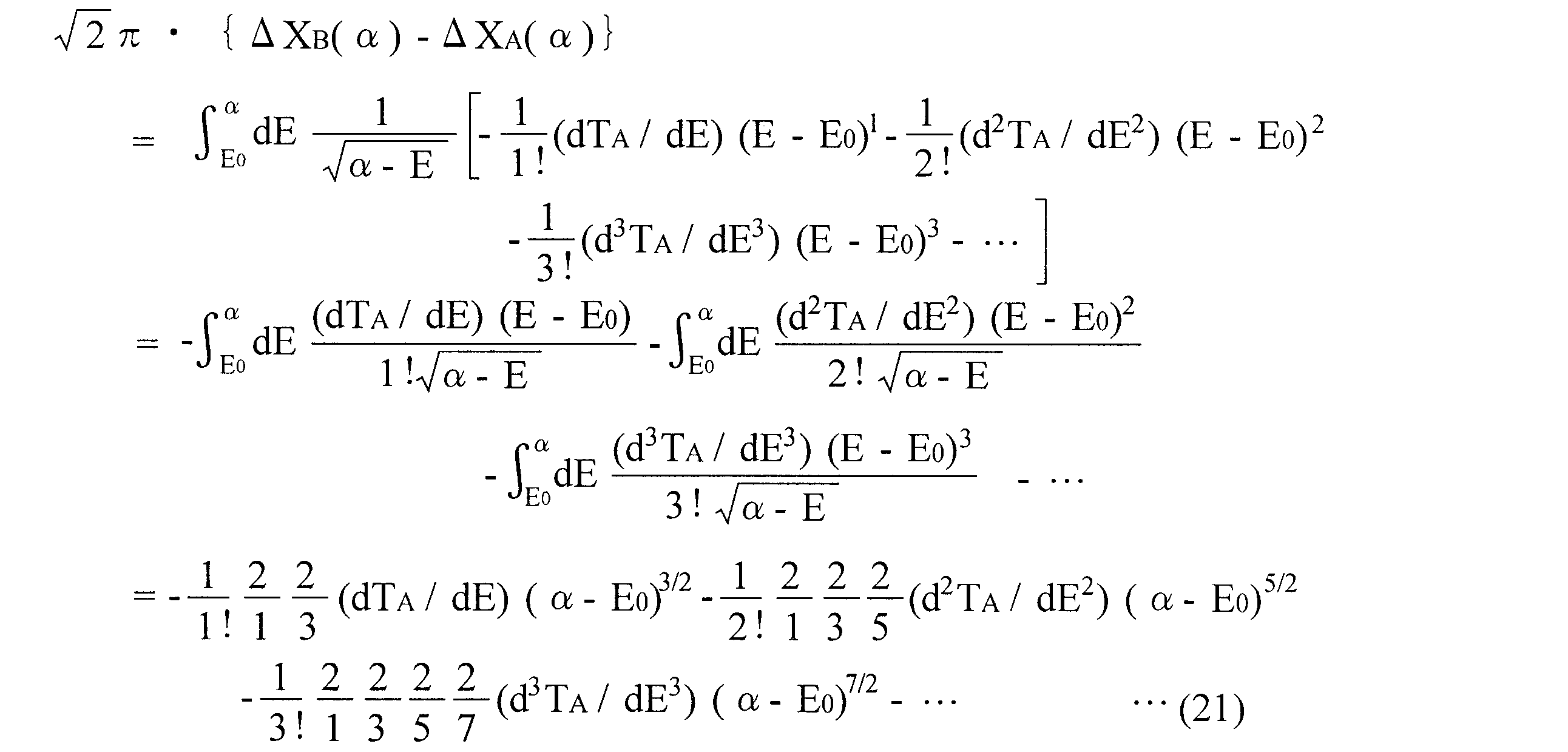
続いて、リフレクタの中心軸に沿って形成されるリアル電位XR(U)が与えられたときに、ベース電位XA(U)と補正電位XC(U)の寄与を識別する一つの方法について述べる。なお、ここで述べる方法は、ベース電位XA(U)と補正電位XC(U)とが共に非一様電場によるものであってもよく、グリッド電極での電場の染み出しがある場合や、グリッド電極を用いない場合においても適用可能である。
まず、エネルギEに対する全飛行時間T(E)を調べる。これは図10(b)中に実線で示した「リアル電位による全飛行時間」である。E≧E0では飛行時間は理想的には一定となる。次に、E≧E0でのベース電位による全飛行時間TD(E)を、E<E0での関数形から外挿により決める。これは、2次収束点E=E0における飛行時間のエネルギに関する微分係数が無限に高次の項まで連続であるという条件から求まる。つまり、E=E0の低エネルギ側から近付いたときの微分係数(dT/dE)E→E0-、(d2T/dE2)E→E0-、(d3T/dE3)E→E0-、…を用いて、TD(E)のE≧E0での関数形を予測する。そして、(13-3)式の右辺にTD(E0)-TD(E)を代入することにより補正電位XC(U)が求まる。また、リアル電位XR(U)から補正電位XC(U)を差し引くことで、ベース電位XA(U)を求めることができる。
次に、上述した特徴的なイオンリフレクタを備えた本発明の一実施例であるTOFMSについて説明する。図22は本実施例のTOFMSの概略構成図である。
(i)ステージの段数やグリッド電極の有無など、リフレクタの形状は一切問わない。
(ii)リフレクタ内部は中空であって、イオンを反射させるための単調に変化する(分析対象が正イオンである場合は単調増加する、分析対象が負イオンである場合は単調減少する)傾斜電位さえあればよく、その傾斜電位が一様電場によるものか或いは非一様電場によるものかは問わない。
(iii)或るエネルギ範囲でエネルギ収束(飛行時間が初期エネルギに依存しない)が達成されるべく、M次収束条件を満たすように調整が施されている。例えば上記実施例での説明の通り、ワイリー・マクラーレン解のときは1次収束条件、マミリン解のときは2次収束条件などである。この延長で、M段式リフレクタを用いる場合には、最大でM次収束条件を満たすように調整することができる。グリッドレス構造のリフレクトロンの場合には、マルチステージ式の場合とは異なり収束条件を解析的に求めることはできないが、数値計算などによりM次収束条件を求めればよい。一般化すれば、ベースとなるリフレクトロンでは、解析的に又は数値計算によりM次収束条件を求め、これをエネルギ収束に利用している。
2…加速電極
3…フライトチューブ
4…イオンリフレクタ
41…ガードリング電極
5…検出器
6…リフレクタ直流電圧源
7…加速電圧源
8…制御部
9…データ処理部
Claims (20)
- 分析対象のイオンに一定のエネルギを付与して加速するイオン射出部と、該イオン射出部から射出されたイオンを電場の作用により反射して折り返すためのイオンリフレクタと、該イオンリフレクタで反射され該イオンリフレクタを出て来たイオンを検出するイオン検出器と、前記イオンリフレクタの内部に反射電場を形成するために該イオンリフレクタを駆動するリフレクタ駆動手段と、を具備する飛行時間型質量分析装置において、前記リフレクタ駆動手段は、
前記イオンリフレクタの中心軸に沿った座標をXとしたとき、該イオンリフレクタの中心軸に沿って、該イオンリフレクタの全体に亘り電位が単調に変化し、その結果、逆関数XA(U)も一意的に得られる所定の電位分布UA(X)が該イオンリフレクタの中空領域に形成されるように該イオンリフレクタに電圧を印加することで、該イオンリフレクタ内部の座標X0で電位E0である位置にN次収束位置を形成するとともに、
座標X0であるN次収束位置を始点とする奥側の空間において、前記座標X0の近傍では{U(X)-E0}N+3/2に比例する式で近似でき、且つ前記座標X0から奥側において滑らかな関数となる所定の補正電位XC(U)を、前記所定の電位XA(U)に重畳させるように、前記イオンリフレクタに電圧を印加することを特徴とする飛行時間型質量分析装置。 - 請求項1に記載の飛行時間型質量分析装置において、
前記イオン射出部と前記イオンリフレクタとの間に、該イオン射出部から出たイオンを前方へ向けて飛行させるための前方イオンドリフト部を備え、前記イオンリフレクタは該前方イオンドリフト部を通過したイオンを次に電場の作用により反射して折り返し、
さらに、該イオンリフレクタと前記イオン検出器との間に、該イオンリフレクタで反射され該イオンリフレクタを出て来たイオンを次に前記前方イオンドリフト部とは逆方向に飛行させるための後方イオンドリフト部を備えることを特徴とする飛行時間型質量分析装置。 - 請求項1に記載の飛行時間型質量分析装置において、
前記イオン射出部と前記イオンリフレクタ、又は該イオンリフレクタと前記イオン検出器の少なくとも一方は、間に空間を介さずに接続されていることを特徴とする飛行時間型質量分析装置。 - 請求項1~3のいずれかに記載の飛行時間型質量分析装置において、
前記所定の電位分布XA(U)となる電場は少なくとも前記座標X0の近傍で一様電場であることを特徴とする飛行時間型質量分析装置。 - 請求項1~4のいずれかに記載の飛行時間型質量分析装置において、
前記イオンリフレクタの中空領域にはグリッド電極が配設され、該グリッド電極により該イオンリフレクタが複数のステージに分割されてなることを特徴とする飛行時間型質量分析装置。 - 請求項1~4のいずれかに記載の飛行時間型質量分析装置において、
前記イオンリフレクタの中空領域にはグリッド電極が無いグリッドレス構造であることを特徴とする飛行時間型質量分析装置。 - 請求項1~6のいずれかに記載の飛行時間型質量分析装置において、
前記イオンリフレクタはシングルステージ式であって、該イオンリフレクタ内部の1次収束位置を始点とする該始点の境界付近に、N=1である{U(X)-E0}2.5に比例する補正電位を重畳することを特徴とする飛行時間型質量分析装置。 - 請求項1~6のいずれかに記載の飛行時間型質量分析装置において、
前記イオンリフレクタはデュアルステージ式であって、該イオンリフレクタ内部の2次収束位置を始点とする該始点の境界付近に、N=2である{U(X)-E0}3.5に比例する補正電位を重畳することを特徴とする飛行時間型質量分析装置。 - 請求項1~6のいずれかに記載の飛行時間型質量分析装置において、
前記イオンリフレクタはデュアルステージ式であって、該イオンリフレクタ内部の1次収束位置を始点とする該始点の境界付近に、N=1である{U(X)-E0}2.5に比例する補正電位を重畳することを特徴とする飛行時間型質量分析装置。 - 請求項1~9のいずれかに記載の飛行時間型質量分析装置において、
前記イオン射出部は直交加速型であることを特徴とする飛行時間型質量分析装置。 - 請求項1~9のいずれかに記載の飛行時間型質量分析装置において、
前記イオン射出部はMALDIイオン源であることを特徴とする飛行時間型質量分析装置。 - 請求項1~11のいずれかに記載の飛行時間型質量分析装置において、
前記前方イオンドリフト部及び/又は後方イオンドリフト部の一部に加減速部を設けたことを特徴とする飛行時間型質量分析装置。 - 請求項1~12のいずれかに記載の飛行時間型質量分析装置において、
前記前方イオンドリフト部の一部に収束レンズを設けたことを特徴とする飛行時間型質量分析装置。 - 請求項1~13のいずれかに記載の飛行時間型質量分析装置において、
前記イオン射出部は収束レンズの機能を有することを特徴とする飛行時間型質量分析装置。 - 請求項1~14のいずれかに記載の飛行時間型質量分析装置において、
前記イオン射出部と前記イオンリフレクタとの間にイオンの通過範囲を制限するアパーチャ又はスリットを設置することを特徴とする飛行時間型質量分析装置。 - 請求項1~15のいずれかに記載の飛行時間型質量分析装置において、
前記イオン射出部、又はイオンリフレクタの電極の一部は、イオンの通過範囲を制限する機能を有することを特徴とする飛行時間型質量分析装置。 - 請求項1~16のいずれかに記載の飛行時間型質量分析装置において、
前記イオンリフレクタはイオン光軸に沿って配列された複数の薄型電極を含むことを特徴とする飛行時間型質量分析装置。 - 請求項1~16のいずれかに記載の飛行時間型質量分析装置において、
前記イオンリフレクタはイオン光軸に沿って電気抵抗が調整された抵抗体を含むことを特徴とする飛行時間型質量分析装置。 - 請求項1~16のいずれかに記載の飛行時間型質量分析装置において、
前記イオンリフレクタはプリント基板や微細加工基板を用いて構成されることを特徴とする飛行時間型質量分析装置。 - 請求項1~19のいずれかに記載の飛行時間型質量分析装置において、
複数のイオンリフレクタを対向して設置し、その複数のイオンリフレクタ間でイオンを複数回反射させる多重反射飛行時間型質量分析装置であって、その複数のイオンリフレクタのうちの少なくとも一つは、所定の補正電位XC(U)が前記所定の電位XA(U)に重畳された前記イオンリフレクタであることを特徴とする飛行時間型質量分析装置。
Priority Applications (5)
| Application Number | Priority Date | Filing Date | Title |
|---|---|---|---|
| CN201180068055.0A CN103380479B (zh) | 2010-12-20 | 2011-12-20 | 飞行时间型质量分析装置 |
| EP17202314.5A EP3306640B1 (en) | 2010-12-20 | 2011-12-20 | Time-of-flight mass spectrometer |
| US13/996,372 US8772708B2 (en) | 2010-12-20 | 2011-12-20 | Time-of-flight mass spectrometer |
| JP2012549822A JP5629928B2 (ja) | 2010-12-20 | 2011-12-20 | 飛行時間型質量分析装置 |
| EP11851297.9A EP2669930B1 (en) | 2010-12-20 | 2011-12-20 | Time-of-flight mass spectrometer |
Applications Claiming Priority (2)
| Application Number | Priority Date | Filing Date | Title |
|---|---|---|---|
| JP2010283187 | 2010-12-20 | ||
| JP2010-283187 | 2010-12-20 |
Publications (1)
| Publication Number | Publication Date |
|---|---|
| WO2012086630A1 true WO2012086630A1 (ja) | 2012-06-28 |
Family
ID=46313899
Family Applications (1)
| Application Number | Title | Priority Date | Filing Date |
|---|---|---|---|
| PCT/JP2011/079471 Ceased WO2012086630A1 (ja) | 2010-12-20 | 2011-12-20 | 飛行時間型質量分析装置 |
Country Status (5)
| Country | Link |
|---|---|
| US (1) | US8772708B2 (ja) |
| EP (2) | EP2669930B1 (ja) |
| JP (2) | JP5629928B2 (ja) |
| CN (1) | CN103380479B (ja) |
| WO (1) | WO2012086630A1 (ja) |
Cited By (5)
| Publication number | Priority date | Publication date | Assignee | Title |
|---|---|---|---|---|
| WO2014057777A1 (ja) | 2012-10-10 | 2014-04-17 | 株式会社島津製作所 | 飛行時間型質量分析装置 |
| WO2016103339A1 (ja) * | 2014-12-24 | 2016-06-30 | 株式会社島津製作所 | 飛行時間型質量分析装置 |
| JP2017195183A (ja) * | 2016-04-19 | 2017-10-26 | 亨 絹川 | 飛行時間型質量分析装置 |
| US9892902B2 (en) | 2015-11-26 | 2018-02-13 | Shimadzu Corporation | Ion radiation device and surface analyzer using said device |
| US11862451B2 (en) | 2021-07-21 | 2024-01-02 | Shimadzu Corporation | Orthogonal acceleration time-of-flight mass spectrometer |
Families Citing this family (29)
| Publication number | Priority date | Publication date | Assignee | Title |
|---|---|---|---|---|
| US10621042B2 (en) * | 2014-12-31 | 2020-04-14 | Pure Storage, Inc. | Vault transformation within a dispersed storage network |
| GB201507363D0 (en) | 2015-04-30 | 2015-06-17 | Micromass Uk Ltd And Leco Corp | Multi-reflecting TOF mass spectrometer |
| GB201520130D0 (en) | 2015-11-16 | 2015-12-30 | Micromass Uk Ltd And Leco Corp | Imaging mass spectrometer |
| GB201520134D0 (en) | 2015-11-16 | 2015-12-30 | Micromass Uk Ltd And Leco Corp | Imaging mass spectrometer |
| GB201520540D0 (en) | 2015-11-23 | 2016-01-06 | Micromass Uk Ltd And Leco Corp | Improved ion mirror and ion-optical lens for imaging |
| WO2017122276A1 (ja) * | 2016-01-12 | 2017-07-20 | 株式会社島津製作所 | 飛行時間型質量分析装置 |
| GB201613988D0 (en) | 2016-08-16 | 2016-09-28 | Micromass Uk Ltd And Leco Corp | Mass analyser having extended flight path |
| GB2558221B (en) * | 2016-12-22 | 2022-07-20 | Micromass Ltd | Ion mobility separation exit transmission control |
| GB2567794B (en) | 2017-05-05 | 2023-03-08 | Micromass Ltd | Multi-reflecting time-of-flight mass spectrometers |
| GB2563571B (en) | 2017-05-26 | 2023-05-24 | Micromass Ltd | Time of flight mass analyser with spatial focussing |
| US11211238B2 (en) | 2017-08-06 | 2021-12-28 | Micromass Uk Limited | Multi-pass mass spectrometer |
| US11081332B2 (en) | 2017-08-06 | 2021-08-03 | Micromass Uk Limited | Ion guide within pulsed converters |
| EP3662501A1 (en) | 2017-08-06 | 2020-06-10 | Micromass UK Limited | Ion mirror for multi-reflecting mass spectrometers |
| WO2019030473A1 (en) | 2017-08-06 | 2019-02-14 | Anatoly Verenchikov | FIELDS FOR SMART REFLECTIVE TOF SM |
| EP3662503A1 (en) | 2017-08-06 | 2020-06-10 | Micromass UK Limited | Ion injection into multi-pass mass spectrometers |
| US11295944B2 (en) | 2017-08-06 | 2022-04-05 | Micromass Uk Limited | Printed circuit ion mirror with compensation |
| US11817303B2 (en) | 2017-08-06 | 2023-11-14 | Micromass Uk Limited | Accelerator for multi-pass mass spectrometers |
| GB2568354B (en) * | 2017-09-28 | 2022-08-10 | Bruker Daltonics Gmbh & Co Kg | Wide-range high mass resolution in reflector time-of-flight mass spectrometers |
| GB201806507D0 (en) * | 2018-04-20 | 2018-06-06 | Verenchikov Anatoly | Gridless ion mirrors with smooth fields |
| GB201807605D0 (en) | 2018-05-10 | 2018-06-27 | Micromass Ltd | Multi-reflecting time of flight mass analyser |
| GB201807626D0 (en) | 2018-05-10 | 2018-06-27 | Micromass Ltd | Multi-reflecting time of flight mass analyser |
| WO2019220553A1 (ja) | 2018-05-16 | 2019-11-21 | 株式会社島津製作所 | 飛行時間型質量分析装置 |
| GB201808459D0 (en) * | 2018-05-23 | 2018-07-11 | Thermo Fisher Scient Bremen Gmbh | Ion front tilt correction for time of flight(tof) mass spectrometer |
| GB201808530D0 (en) | 2018-05-24 | 2018-07-11 | Verenchikov Anatoly | TOF MS detection system with improved dynamic range |
| GB201810573D0 (en) | 2018-06-28 | 2018-08-15 | Verenchikov Anatoly | Multi-pass mass spectrometer with improved duty cycle |
| GB201901411D0 (en) | 2019-02-01 | 2019-03-20 | Micromass Ltd | Electrode assembly for mass spectrometer |
| GB201903779D0 (en) | 2019-03-20 | 2019-05-01 | Micromass Ltd | Multiplexed time of flight mass spectrometer |
| JP7322650B2 (ja) * | 2019-10-11 | 2023-08-08 | 株式会社島津製作所 | マルチターン型飛行時間型質量分析装置及びその製造方法 |
| CN118862313B (zh) * | 2024-09-24 | 2024-12-06 | 中国空气动力研究与发展中心计算空气动力研究所 | 一种飞行器流场等离子体环境收敛判别方法 |
Citations (4)
| Publication number | Priority date | Publication date | Assignee | Title |
|---|---|---|---|---|
| US4625112A (en) | 1983-11-30 | 1986-11-25 | Shimadzu Corporation | Time of flight mass spectrometer |
| US5464985A (en) | 1993-10-01 | 1995-11-07 | The Johns Hopkins University | Non-linear field reflectron |
| US6365892B1 (en) | 1997-11-24 | 2002-04-02 | Robert J. Cotter | Method and apparatus for correction of initial ion velocity in a reflectron time-of-flight mass spectrometer |
| JP3797200B2 (ja) | 2001-11-09 | 2006-07-12 | 株式会社島津製作所 | 飛行時間型質量分析装置 |
Family Cites Families (14)
| Publication number | Priority date | Publication date | Assignee | Title |
|---|---|---|---|---|
| US5300774A (en) * | 1991-04-25 | 1994-04-05 | Applied Biosystems, Inc. | Time-of-flight mass spectrometer with an aperture enabling tradeoff of transmission efficiency and resolution |
| DE4322101C2 (de) * | 1993-07-02 | 1995-06-14 | Bergmann Thorald | Ionenquelle für Flugzeit-Massenspektrometer |
| AU2622195A (en) * | 1994-05-31 | 1995-12-21 | University Of Warwick | Tandem mass spectrometry apparatus |
| US5942758A (en) * | 1997-09-10 | 1999-08-24 | Bruker Daltronics, Inc. | Shielded lens |
| US6518569B1 (en) * | 1999-06-11 | 2003-02-11 | Science & Technology Corporation @ Unm | Ion mirror |
| DE10005698B4 (de) * | 2000-02-09 | 2007-03-01 | Bruker Daltonik Gmbh | Gitterloses Reflektor-Flugzeitmassenspektrometer für orthogonalen Ioneneinschuss |
| WO2002001599A2 (en) * | 2000-06-28 | 2002-01-03 | The Johns Hopkins University | Time-of-flight mass spectrometer array instrument |
| DE10156604A1 (de) * | 2001-11-17 | 2003-05-28 | Bruker Daltonik Gmbh | Raumwinkelfokussierender Reflektor für Flugzeitmassenspektrometer |
| US6900431B2 (en) * | 2003-03-21 | 2005-05-31 | Predicant Biosciences, Inc. | Multiplexed orthogonal time-of-flight mass spectrometer |
| US6998607B1 (en) * | 2004-08-31 | 2006-02-14 | Thermo Finnigan Llc | Temperature compensated time-of-flight mass spectrometer |
| JP4691712B2 (ja) * | 2005-03-17 | 2011-06-01 | 独立行政法人産業技術総合研究所 | 飛行時間質量分析計 |
| CN107833823B (zh) * | 2005-10-11 | 2021-09-17 | 莱克公司 | 具有正交加速的多次反射飞行时间质谱仪 |
| US7589319B2 (en) * | 2007-05-01 | 2009-09-15 | Virgin Instruments Corporation | Reflector TOF with high resolution and mass accuracy for peptides and small molecules |
| EP2413346B1 (en) * | 2009-03-27 | 2022-05-04 | Osaka University | Ion source, and mass spectroscope provided with same |
-
2011
- 2011-12-20 US US13/996,372 patent/US8772708B2/en active Active
- 2011-12-20 EP EP11851297.9A patent/EP2669930B1/en active Active
- 2011-12-20 WO PCT/JP2011/079471 patent/WO2012086630A1/ja not_active Ceased
- 2011-12-20 EP EP17202314.5A patent/EP3306640B1/en active Active
- 2011-12-20 CN CN201180068055.0A patent/CN103380479B/zh active Active
- 2011-12-20 JP JP2012549822A patent/JP5629928B2/ja active Active
-
2014
- 2014-09-17 JP JP2014188598A patent/JP5924387B2/ja active Active
Patent Citations (4)
| Publication number | Priority date | Publication date | Assignee | Title |
|---|---|---|---|---|
| US4625112A (en) | 1983-11-30 | 1986-11-25 | Shimadzu Corporation | Time of flight mass spectrometer |
| US5464985A (en) | 1993-10-01 | 1995-11-07 | The Johns Hopkins University | Non-linear field reflectron |
| US6365892B1 (en) | 1997-11-24 | 2002-04-02 | Robert J. Cotter | Method and apparatus for correction of initial ion velocity in a reflectron time-of-flight mass spectrometer |
| JP3797200B2 (ja) | 2001-11-09 | 2006-07-12 | 株式会社島津製作所 | 飛行時間型質量分析装置 |
Non-Patent Citations (10)
Cited By (10)
| Publication number | Priority date | Publication date | Assignee | Title |
|---|---|---|---|---|
| WO2014057777A1 (ja) | 2012-10-10 | 2014-04-17 | 株式会社島津製作所 | 飛行時間型質量分析装置 |
| JP5862791B2 (ja) * | 2012-10-10 | 2016-02-16 | 株式会社島津製作所 | 飛行時間型質量分析装置 |
| US9490114B2 (en) | 2012-10-10 | 2016-11-08 | Shimadzu Corporation | Time-of-flight mass spectrometer |
| EP2908329B1 (en) * | 2012-10-10 | 2022-01-12 | Shimadzu Corporation | Time-of-flight mass spectrometer |
| WO2016103339A1 (ja) * | 2014-12-24 | 2016-06-30 | 株式会社島津製作所 | 飛行時間型質量分析装置 |
| JPWO2016103339A1 (ja) * | 2014-12-24 | 2017-04-27 | 株式会社島津製作所 | 飛行時間型質量分析装置 |
| US10186413B2 (en) | 2014-12-24 | 2019-01-22 | Shimadzu Corporation | Time-of-flight mass spectrometer |
| US9892902B2 (en) | 2015-11-26 | 2018-02-13 | Shimadzu Corporation | Ion radiation device and surface analyzer using said device |
| JP2017195183A (ja) * | 2016-04-19 | 2017-10-26 | 亨 絹川 | 飛行時間型質量分析装置 |
| US11862451B2 (en) | 2021-07-21 | 2024-01-02 | Shimadzu Corporation | Orthogonal acceleration time-of-flight mass spectrometer |
Also Published As
| Publication number | Publication date |
|---|---|
| EP2669930A4 (en) | 2015-12-23 |
| EP3306640B1 (en) | 2024-04-10 |
| US8772708B2 (en) | 2014-07-08 |
| CN103380479B (zh) | 2016-01-20 |
| JPWO2012086630A1 (ja) | 2014-05-22 |
| EP2669930B1 (en) | 2018-02-14 |
| EP2669930A1 (en) | 2013-12-04 |
| JP2014241298A (ja) | 2014-12-25 |
| JP5924387B2 (ja) | 2016-05-25 |
| CN103380479A (zh) | 2013-10-30 |
| EP3306640A1 (en) | 2018-04-11 |
| JP5629928B2 (ja) | 2014-11-26 |
| US20140054456A1 (en) | 2014-02-27 |
Similar Documents
| Publication | Publication Date | Title |
|---|---|---|
| JP5629928B2 (ja) | 飛行時間型質量分析装置 | |
| JP5914515B2 (ja) | 改善された空間フォーカス飛行時間質量分析計 | |
| JP6203749B2 (ja) | 飛行時間におけるフィールドフリー領域を用いた一次および二次の集束 | |
| US10141176B2 (en) | Multi-reflection mass spectrometer with deceleration stage | |
| EP2686870B1 (en) | Electrostatic gimbal for correction of errors in time of flight mass spectrometers | |
| JP6287419B2 (ja) | 飛行時間型質量分析装置 | |
| JP5862791B2 (ja) | 飛行時間型質量分析装置 | |
| US7709789B2 (en) | TOF mass spectrometry with correction for trajectory error | |
| EP2710622B1 (en) | Segmented planar calibration for correction of errors in time of flight mass spectrometers | |
| CN105009251A (zh) | 多反射质谱仪 | |
| JP6292319B2 (ja) | 飛行時間型質量分析装置 | |
| JP6160472B2 (ja) | 飛行時間型質量分析装置 | |
| JP6346973B2 (ja) | 飛行時間型質量分析装置 | |
| Kozlov et al. | Modeling Known Sources of Mass Calibration Deviations in High Resolution ToF MS | |
| Poteshin et al. | The 2nd Order Focusing by Energy for TOF Sector Field Mass Analyzer with an Orthogonal Acceleration: Theory, Modeling, Experiment |
Legal Events
| Date | Code | Title | Description |
|---|---|---|---|
| WWE | Wipo information: entry into national phase |
Ref document number: 201180068055.0 Country of ref document: CN |
|
| 121 | Ep: the epo has been informed by wipo that ep was designated in this application |
Ref document number: 11851297 Country of ref document: EP Kind code of ref document: A1 |
|
| ENP | Entry into the national phase |
Ref document number: 2012549822 Country of ref document: JP Kind code of ref document: A |
|
| NENP | Non-entry into the national phase |
Ref country code: DE |
|
| WWE | Wipo information: entry into national phase |
Ref document number: 2011851297 Country of ref document: EP |
|
| WWE | Wipo information: entry into national phase |
Ref document number: 13996372 Country of ref document: US |