WO2012086814A1 - ハニカム構造体 - Google Patents
ハニカム構造体 Download PDFInfo
- Publication number
- WO2012086814A1 WO2012086814A1 PCT/JP2011/079936 JP2011079936W WO2012086814A1 WO 2012086814 A1 WO2012086814 A1 WO 2012086814A1 JP 2011079936 W JP2011079936 W JP 2011079936W WO 2012086814 A1 WO2012086814 A1 WO 2012086814A1
- Authority
- WO
- WIPO (PCT)
- Prior art keywords
- honeycomb structure
- electrode
- silicon carbide
- outer peripheral
- pair
- Prior art date
- Legal status (The legal status is an assumption and is not a legal conclusion. Google has not performed a legal analysis and makes no representation as to the accuracy of the status listed.)
- Ceased
Links
Images




Classifications
-
- F—MECHANICAL ENGINEERING; LIGHTING; HEATING; WEAPONS; BLASTING
- F01—MACHINES OR ENGINES IN GENERAL; ENGINE PLANTS IN GENERAL; STEAM ENGINES
- F01N—GAS-FLOW SILENCERS OR EXHAUST APPARATUS FOR MACHINES OR ENGINES IN GENERAL; GAS-FLOW SILENCERS OR EXHAUST APPARATUS FOR INTERNAL-COMBUSTION ENGINES
- F01N3/00—Exhaust or silencing apparatus having means for purifying, rendering innocuous, or otherwise treating exhaust
- F01N3/08—Exhaust or silencing apparatus having means for purifying, rendering innocuous, or otherwise treating exhaust for rendering innocuous
- F01N3/10—Exhaust or silencing apparatus having means for purifying, rendering innocuous, or otherwise treating exhaust for rendering innocuous by thermal or catalytic conversion of noxious components of exhaust
- F01N3/18—Exhaust or silencing apparatus having means for purifying, rendering innocuous, or otherwise treating exhaust for rendering innocuous by thermal or catalytic conversion of noxious components of exhaust characterised by methods of operation; Control
- F01N3/20—Exhaust or silencing apparatus having means for purifying, rendering innocuous, or otherwise treating exhaust for rendering innocuous by thermal or catalytic conversion of noxious components of exhaust characterised by methods of operation; Control specially adapted for catalytic conversion
- F01N3/2006—Periodically heating or cooling catalytic reactors, e.g. at cold starting or overheating
- F01N3/2013—Periodically heating or cooling catalytic reactors, e.g. at cold starting or overheating using electric or magnetic heating means
- F01N3/2026—Periodically heating or cooling catalytic reactors, e.g. at cold starting or overheating using electric or magnetic heating means directly electrifying the catalyst substrate, i.e. heating the electrically conductive catalyst substrate by joule effect
-
- H—ELECTRICITY
- H05—ELECTRIC TECHNIQUES NOT OTHERWISE PROVIDED FOR
- H05B—ELECTRIC HEATING; ELECTRIC LIGHT SOURCES NOT OTHERWISE PROVIDED FOR; CIRCUIT ARRANGEMENTS FOR ELECTRIC LIGHT SOURCES, IN GENERAL
- H05B3/00—Ohmic-resistance heating
- H05B3/02—Details
- H05B3/03—Electrodes
-
- C—CHEMISTRY; METALLURGY
- C04—CEMENTS; CONCRETE; ARTIFICIAL STONE; CERAMICS; REFRACTORIES
- C04B—LIME, MAGNESIA; SLAG; CEMENTS; COMPOSITIONS THEREOF, e.g. MORTARS, CONCRETE OR LIKE BUILDING MATERIALS; ARTIFICIAL STONE; CERAMICS; REFRACTORIES; TREATMENT OF NATURAL STONE
- C04B35/00—Shaped ceramic products characterised by their composition; Ceramics compositions; Processing powders of inorganic compounds preparatory to the manufacturing of ceramic products
- C04B35/515—Shaped ceramic products characterised by their composition; Ceramics compositions; Processing powders of inorganic compounds preparatory to the manufacturing of ceramic products based on non-oxide ceramics
- C04B35/56—Shaped ceramic products characterised by their composition; Ceramics compositions; Processing powders of inorganic compounds preparatory to the manufacturing of ceramic products based on non-oxide ceramics based on carbides or oxycarbides
- C04B35/565—Shaped ceramic products characterised by their composition; Ceramics compositions; Processing powders of inorganic compounds preparatory to the manufacturing of ceramic products based on non-oxide ceramics based on carbides or oxycarbides based on silicon carbide
-
- C—CHEMISTRY; METALLURGY
- C04—CEMENTS; CONCRETE; ARTIFICIAL STONE; CERAMICS; REFRACTORIES
- C04B—LIME, MAGNESIA; SLAG; CEMENTS; COMPOSITIONS THEREOF, e.g. MORTARS, CONCRETE OR LIKE BUILDING MATERIALS; ARTIFICIAL STONE; CERAMICS; REFRACTORIES; TREATMENT OF NATURAL STONE
- C04B38/00—Porous mortars, concrete, artificial stone or ceramic ware; Preparation thereof
- C04B38/0006—Honeycomb structures
-
- F—MECHANICAL ENGINEERING; LIGHTING; HEATING; WEAPONS; BLASTING
- F01—MACHINES OR ENGINES IN GENERAL; ENGINE PLANTS IN GENERAL; STEAM ENGINES
- F01N—GAS-FLOW SILENCERS OR EXHAUST APPARATUS FOR MACHINES OR ENGINES IN GENERAL; GAS-FLOW SILENCERS OR EXHAUST APPARATUS FOR INTERNAL-COMBUSTION ENGINES
- F01N3/00—Exhaust or silencing apparatus having means for purifying, rendering innocuous, or otherwise treating exhaust
- F01N3/08—Exhaust or silencing apparatus having means for purifying, rendering innocuous, or otherwise treating exhaust for rendering innocuous
- F01N3/10—Exhaust or silencing apparatus having means for purifying, rendering innocuous, or otherwise treating exhaust for rendering innocuous by thermal or catalytic conversion of noxious components of exhaust
- F01N3/24—Exhaust or silencing apparatus having means for purifying, rendering innocuous, or otherwise treating exhaust for rendering innocuous by thermal or catalytic conversion of noxious components of exhaust characterised by constructional aspects of converting apparatus
- F01N3/28—Construction of catalytic reactors
- F01N3/2803—Construction of catalytic reactors characterised by structure, by material or by manufacturing of catalyst support
- F01N3/2825—Ceramics
- F01N3/2828—Ceramic multi-channel monoliths, e.g. honeycombs
-
- H—ELECTRICITY
- H05—ELECTRIC TECHNIQUES NOT OTHERWISE PROVIDED FOR
- H05B—ELECTRIC HEATING; ELECTRIC LIGHT SOURCES NOT OTHERWISE PROVIDED FOR; CIRCUIT ARRANGEMENTS FOR ELECTRIC LIGHT SOURCES, IN GENERAL
- H05B3/00—Ohmic-resistance heating
- H05B3/10—Heating elements characterised by the composition or nature of the materials or by the arrangement of the conductor
- H05B3/12—Heating elements characterised by the composition or nature of the materials or by the arrangement of the conductor characterised by the composition or nature of the conductive material
- H05B3/14—Heating elements characterised by the composition or nature of the materials or by the arrangement of the conductor characterised by the composition or nature of the conductive material the material being non-metallic
- H05B3/141—Conductive ceramics, e.g. metal oxides, metal carbides, barium titanate, ferrites, zirconia, vitrous compounds
-
- H—ELECTRICITY
- H05—ELECTRIC TECHNIQUES NOT OTHERWISE PROVIDED FOR
- H05B—ELECTRIC HEATING; ELECTRIC LIGHT SOURCES NOT OTHERWISE PROVIDED FOR; CIRCUIT ARRANGEMENTS FOR ELECTRIC LIGHT SOURCES, IN GENERAL
- H05B3/00—Ohmic-resistance heating
- H05B3/40—Heating elements having the shape of rods or tubes
- H05B3/42—Heating elements having the shape of rods or tubes non-flexible
-
- B—PERFORMING OPERATIONS; TRANSPORTING
- B01—PHYSICAL OR CHEMICAL PROCESSES OR APPARATUS IN GENERAL
- B01J—CHEMICAL OR PHYSICAL PROCESSES, e.g. CATALYSIS OR COLLOID CHEMISTRY; THEIR RELEVANT APPARATUS
- B01J35/00—Catalysts, in general, characterised by their form or physical properties
- B01J35/30—Catalysts, in general, characterised by their form or physical properties characterised by their physical properties
- B01J35/33—Electric or magnetic properties
-
- C—CHEMISTRY; METALLURGY
- C04—CEMENTS; CONCRETE; ARTIFICIAL STONE; CERAMICS; REFRACTORIES
- C04B—LIME, MAGNESIA; SLAG; CEMENTS; COMPOSITIONS THEREOF, e.g. MORTARS, CONCRETE OR LIKE BUILDING MATERIALS; ARTIFICIAL STONE; CERAMICS; REFRACTORIES; TREATMENT OF NATURAL STONE
- C04B2111/00—Mortars, concrete or artificial stone or mixtures to prepare them, characterised by specific function, property or use
- C04B2111/90—Electrical properties
- C04B2111/94—Electrically conducting materials
-
- C—CHEMISTRY; METALLURGY
- C04—CEMENTS; CONCRETE; ARTIFICIAL STONE; CERAMICS; REFRACTORIES
- C04B—LIME, MAGNESIA; SLAG; CEMENTS; COMPOSITIONS THEREOF, e.g. MORTARS, CONCRETE OR LIKE BUILDING MATERIALS; ARTIFICIAL STONE; CERAMICS; REFRACTORIES; TREATMENT OF NATURAL STONE
- C04B2235/00—Aspects relating to ceramic starting mixtures or sintered ceramic products
- C04B2235/02—Composition of constituents of the starting material or of secondary phases of the final product
- C04B2235/30—Constituents and secondary phases not being of a fibrous nature
- C04B2235/38—Non-oxide ceramic constituents or additives
- C04B2235/3817—Carbides
- C04B2235/3826—Silicon carbides
-
- C—CHEMISTRY; METALLURGY
- C04—CEMENTS; CONCRETE; ARTIFICIAL STONE; CERAMICS; REFRACTORIES
- C04B—LIME, MAGNESIA; SLAG; CEMENTS; COMPOSITIONS THEREOF, e.g. MORTARS, CONCRETE OR LIKE BUILDING MATERIALS; ARTIFICIAL STONE; CERAMICS; REFRACTORIES; TREATMENT OF NATURAL STONE
- C04B2235/00—Aspects relating to ceramic starting mixtures or sintered ceramic products
- C04B2235/02—Composition of constituents of the starting material or of secondary phases of the final product
- C04B2235/30—Constituents and secondary phases not being of a fibrous nature
- C04B2235/42—Non metallic elements added as constituents or additives, e.g. sulfur, phosphor, selenium or tellurium
- C04B2235/428—Silicon
-
- C—CHEMISTRY; METALLURGY
- C04—CEMENTS; CONCRETE; ARTIFICIAL STONE; CERAMICS; REFRACTORIES
- C04B—LIME, MAGNESIA; SLAG; CEMENTS; COMPOSITIONS THEREOF, e.g. MORTARS, CONCRETE OR LIKE BUILDING MATERIALS; ARTIFICIAL STONE; CERAMICS; REFRACTORIES; TREATMENT OF NATURAL STONE
- C04B2235/00—Aspects relating to ceramic starting mixtures or sintered ceramic products
- C04B2235/02—Composition of constituents of the starting material or of secondary phases of the final product
- C04B2235/50—Constituents or additives of the starting mixture chosen for their shape or used because of their shape or their physical appearance
- C04B2235/54—Particle size related information
- C04B2235/5418—Particle size related information expressed by the size of the particles or aggregates thereof
- C04B2235/5436—Particle size related information expressed by the size of the particles or aggregates thereof micrometer sized, i.e. from 1 to 100 micron
-
- H—ELECTRICITY
- H05—ELECTRIC TECHNIQUES NOT OTHERWISE PROVIDED FOR
- H05B—ELECTRIC HEATING; ELECTRIC LIGHT SOURCES NOT OTHERWISE PROVIDED FOR; CIRCUIT ARRANGEMENTS FOR ELECTRIC LIGHT SOURCES, IN GENERAL
- H05B2203/00—Aspects relating to Ohmic resistive heating covered by group H05B3/00
- H05B2203/022—Heaters specially adapted for heating gaseous material
- H05B2203/024—Heaters using beehive flow through structures
-
- Y—GENERAL TAGGING OF NEW TECHNOLOGICAL DEVELOPMENTS; GENERAL TAGGING OF CROSS-SECTIONAL TECHNOLOGIES SPANNING OVER SEVERAL SECTIONS OF THE IPC; TECHNICAL SUBJECTS COVERED BY FORMER USPC CROSS-REFERENCE ART COLLECTIONS [XRACs] AND DIGESTS
- Y02—TECHNOLOGIES OR APPLICATIONS FOR MITIGATION OR ADAPTATION AGAINST CLIMATE CHANGE
- Y02T—CLIMATE CHANGE MITIGATION TECHNOLOGIES RELATED TO TRANSPORTATION
- Y02T10/00—Road transport of goods or passengers
- Y02T10/10—Internal combustion engine [ICE] based vehicles
- Y02T10/12—Improving ICE efficiencies
Definitions
- the present invention relates to a honeycomb structure. More specifically, the present invention relates to a honeycomb structure that is a catalyst carrier and also functions as a heater by applying a voltage, and further has excellent thermal shock resistance.
- a honeycomb structure made of conductive ceramics and having electrodes disposed on both ends is used as a catalyst carrier with a heater (see, for example, Patent Document 3).
- the power source used for the electric system of the car is commonly used. Therefore, for example, a power supply having a high voltage of 200V is used. However, a metal heater has a low electrical resistance. Therefore, when a high voltage power supply as described above is used, there is a problem that an excessive current flows and the power supply circuit may be damaged.
- the heater is made of metal, it is difficult to support the catalyst even if it is processed into a honeycomb structure. Therefore, it was difficult to integrate the heater and the catalyst.
- the heater-supported catalyst carrier in which the electrodes are disposed at both ends of the honeycomb structure made of conductive ceramics may easily deteriorate the electrodes and increase the resistance value. This is because the electrode is directly exposed to exhaust gas when the catalyst support with a heater is mounted on an automobile and used.
- the present invention has been made in view of the above-described problems, and aims to provide a honeycomb structure that is a catalyst carrier and also functions as a heater by applying a voltage, and further has excellent thermal shock resistance. To do.
- the present invention provides the following honeycomb structure.
- a cylindrical honeycomb structure portion having a porous partition wall defining a plurality of cells extending from one end face to the other end face that serves as a fluid flow path and an outer peripheral wall located at the outermost periphery, and the honeycomb
- a pair of electrode portions disposed on a side surface of the structure portion, wherein the honeycomb structure portion has an electrical resistivity of 1 to 200 ⁇ cm, and each of the pair of electrode portions extends from a cell of the honeycomb structure portion.
- the cross section formed in a band shape extending in the direction and orthogonal to the cell extending direction
- one of the electrode portions in the pair of electrode portions is in the honeycomb structure with respect to the other electrode portion in the pair of electrode portions.
- a honeycomb structure disposed on the opposite side across the center of the portion, wherein the total heat capacity of the pair of electrode portions is 2 to 150% of the heat capacity of the entire outer peripheral wall.
- the electrical resistivity of the honeycomb structure part is 1 to 200 ⁇ cm. Therefore, even if a current is supplied using a high voltage power source, the current does not flow excessively and can be suitably used as a heater.
- each of the pair of electrode portions is formed in a strip shape extending in the cell extending direction of the honeycomb structure portion.
- one electrode portion of the pair of electrode portions is centered on the honeycomb structure portion with respect to the other electrode portion of the pair of electrode portions. It is arrange
- the honeycomb structure of the present invention can suppress the uneven temperature distribution when a voltage is applied. Furthermore, in the honeycomb structure of the present invention, the total heat capacity of the pair of electrode portions is 2 to 150% of the heat capacity of the entire outer peripheral wall. Therefore, the honeycomb structure of the present invention suppresses the generation of a large stress in the honeycomb structure portion even when there is a sudden temperature change when the honeycomb structure is used in an exhaust system of an internal combustion engine. Can do. Thereby, it can suppress that a crack arises in a honeycomb structure.
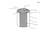
- FIG. 1 is a perspective view schematically showing an embodiment of a honeycomb structure of the present invention.
- 1 is a schematic diagram showing a cross section parallel to a cell extending direction of an embodiment of a honeycomb structure of the present invention.
- FIG. 1 is a schematic diagram showing a cross section orthogonal to a cell extending direction of an embodiment of a honeycomb structure of the present invention. It is a front view which shows typically other embodiment of the honeycomb structure of this invention. It is a schematic diagram which shows the cross section orthogonal to the cell extending direction of other embodiment of the honeycomb structure of this invention.
- FIG. 6 is a front view schematically showing still another embodiment of the honeycomb structure of the present invention.
- FIG. 7 is a schematic diagram showing an A-A ′ cross section in FIG. 6.
- FIG. 6 is a side view schematically showing still another embodiment of the honeycomb structure of the present invention. It is a perspective view which shows typically other embodiment of the honeycomb structure of this invention. It is a schematic diagram which shows the cross section parallel to the cell extending direction of other embodiment of the honeycomb structure of this invention.
- FIG. 6 is a front view schematically showing still another embodiment of the honeycomb structure of the present invention.
- 1 is a schematic diagram showing a cross section orthogonal to a cell extending direction of an embodiment of a honeycomb structure of the present invention.
- honeycomb structure One embodiment of the honeycomb structure of the present invention is a tubular honeycomb structure having a porous partition wall 1 and an outer peripheral wall 3 located at the outermost periphery, as in the honeycomb structure 100 shown in FIGS. Part 4 and a pair of electrode parts 21, 21 arranged on side surface 5 of honeycomb structure part 4.
- the partition wall 1 partitions and forms a plurality of cells 2 "extending from one end surface 11 to the other end surface 12 serving as a fluid flow path".
- the honeycomb structure portion 4 has an electrical resistivity of 1 to 200 ⁇ cm.
- Each of the pair of electrode portions 21 and 21 of the honeycomb structure 100 is formed in a strip shape extending in the extending direction of the cells 2 of the honeycomb structure portion 4.
- FIG. 1 is a perspective view schematically showing one embodiment of a honeycomb structure of the present invention.
- Fig. 2 is a schematic diagram showing a cross section parallel to the cell extending direction of one embodiment of the honeycomb structure of the present invention.
- FIG. 3 is a schematic view showing a cross section perpendicular to the cell extending direction of one embodiment of the honeycomb structure of the present invention. In FIG. 3, the partition walls are omitted.
- the electrical resistivity of the honeycomb structure portion 4 is 1 to 200 ⁇ cm. Therefore, even if a current is supplied using a high voltage power source, the current does not flow excessively and can be suitably used as a heater.
- each of the pair of electrode portions 21 and 21 is formed in a band shape, and one electrode portion 21 is opposite to the other electrode portion 21 with the center of the honeycomb structure portion 4 interposed therebetween. It is arranged on the side. Therefore, it is possible to suppress an uneven temperature distribution of the honeycomb structure portion 4 when a voltage is applied between the pair of electrode portions 21 and 21.
- the total heat capacity of the pair of electrode portions 21 and 21 is 2 to 150% of the heat capacity of the entire outer peripheral wall 3. Therefore, it is possible to suppress the occurrence of large stress in the honeycomb structure portion 4 when there is rapid heating or rapid cooling.
- one electrode portion 21 in the pair of electrode portions 21, 21 is more than the other electrode portion 21 in the pair of electrode portions 21, 21.
- “Disposed on the opposite side across the center O” is defined as follows. In other words, in the cross section perpendicular to the extending direction of the cell 2, the positional relationship is such that the angle ⁇ formed by the line segment (A) and the line segment (B) is in the range of 170 ° to 190 °. This means that the pair of electrode portions 21 and 21 are disposed in the honeycomb structure portion 4.
- the line segment (A) is a line segment connecting the center point of one electrode portion 21 (the center point in the “circumferential direction of the honeycomb structure portion 4”) and the center O of the honeycomb structure portion 4.
- the line segment (B) is a line segment connecting the center point of the other electrode portion 21 (the center point in the “circumferential direction of the honeycomb structure portion 4”) and the center O of the honeycomb structure portion 4.
- the angle ⁇ is an angle centered on the “center O”.
- the material of the partition walls 1 and the outer peripheral wall 3 is preferably a silicon-silicon carbide composite material or a silicon carbide material as a main component, and a silicon-silicon carbide composite material or More preferably, it is a silicon carbide material.
- the material of the partition wall 1 and the outer peripheral wall 3 is mainly composed of a silicon-silicon carbide composite material or a silicon carbide material
- the partition wall 1 and the outer peripheral wall 3 are formed of a silicon-silicon carbide composite material or carbonized carbon. It means that 90% by mass or more of the silicon material is contained.
- the electrical resistivity of the honeycomb structure portion can be set to 1 to 200 ⁇ cm.
- the silicon-silicon carbide composite material contains silicon carbide particles as an aggregate and silicon as a binder for bonding the silicon carbide particles.
- the plurality of silicon carbide particles are preferably bonded by silicon so as to form pores between the silicon carbide particles.
- the silicon carbide material is obtained by sintering silicon carbide particles.
- the electrical resistivity of the honeycomb structure part is a value at 400 ° C.
- a pair of electrode portions 21 and 21 are disposed on the side surface 5 of the honeycomb structure portion 4 (the surface of the outer peripheral wall 3).
- the honeycomb structure 100 of the present embodiment generates heat when a voltage is applied between the pair of electrode portions 21 and 21.
- the applied voltage is preferably 12 to 900V, and more preferably 64 to 600V.
- each of the pair of electrode portions 21 and 21 is formed in a strip shape extending in the direction in which the cells 2 of the honeycomb structure portion 4 extend.
- one electrode portion 21 in the pair of electrode portions 21, 21 has a honeycomb structure with respect to the other electrode portion 21 in the pair of electrode portions 21, 21. It is arranged on the opposite side across the central portion O of the portion 4.
- 0.5 times the central angle ⁇ is preferably 15 to 65 °, and more preferably 30 to 60 °.
- the central angle ⁇ is a central angle of each of the electrode portions 21 and 21 in a cross section orthogonal to the extending direction of the cell 2.
- 0.5 times the central angle ⁇ means an angle ⁇ that is 0.5 times the central angle ⁇ .
- the center angle ⁇ of each electrode portion 21, 21 is 0.5.
- the double angle ⁇ is 15 to 65 °.
- the central angle ⁇ of the electrode portion 21 is two lines connecting the both ends of the electrode portion 21 and the center O of the honeycomb structure portion 4 in a cross section orthogonal to the extending direction of the cell 2.
- the above “angle formed by two line segments” refers to the shape formed by the electrode part 21, the line segment (a), and the line segment (b) in the cross section orthogonal to the extending direction of the cell 2 (for example, , A sector shape) is an inner angle of the center O portion.
- the line segment (a) is a line segment connecting one end of the electrode portion 21 and the center O.
- the line segment (b) is a line segment connecting the other end of the electrode portion 21 and the center O.
- the “angle ⁇ that is 0.5 times the central angle ⁇ ” of the one electrode portion 21 is 0.8 ⁇
- the size is preferably 1.2 times, and more preferably 1.0 times the size (the same size).
- the electrode portion 21 has a shape in which a planar rectangular member is curved along the outer periphery of a cylindrical shape. It has become.
- the shape when the curved electrode portion 21 is deformed so as to be a flat member that is not curved is referred to as a “planar shape” of the electrode portion 21.
- the “planar shape” of the electrode portion 21 shown in FIGS. 1 to 3 is a rectangle.
- the outer peripheral shape of the electrode part means “the outer peripheral shape in the planar shape of the electrode part”.
- the outer peripheral shape of the strip-shaped electrode portion 21 may be rectangular.
- the outer peripheral shape of the strip-shaped electrode portion 21 is “a shape in which rectangular corners are formed in a curved shape”.
- the outer peripheral shape of the strip-shaped electrode portion 21 is “a shape in which rectangular corner portions are linearly chamfered”.
- a combined application of “curved” and “linear” is also preferred.
- the outer peripheral shape of the strip-shaped electrode portion 21 is a rectangle, at least one of the corners is a “shape formed in a curved shape”, and at least one of the corners is “straightly chamfered” It is also preferable that the shape is a “shape”.
- the “strip shape” in this specification can also be referred to as a sheet shape or a film shape. That is, the “electrode part” in the present specification does not include the one that protrudes outward like the “electrode terminal protrusion” in the present specification.
- the outer peripheral shape of the electrode portion 21 is “a shape in which rectangular corners are curved” or “a shape in which rectangular corners are chamfered linearly”. It is possible to further improve the thermal shock resistance.
- the corner portion of the electrode portion is a right angle, the stress in the vicinity of the “corner portion of the electrode portion” in the honeycomb structure portion tends to be relatively high as compared with other portions.
- the corners of the electrode parts are curved or chamfered in a straight line, the stress in the vicinity of the “corner parts of the electrode parts” in the honeycomb structure part can be reduced.
- the electrode portion does not have “a corner portion having an“ inner angle of less than 90 ° ””.
- the electrode portion has a “corner portion with an“ inner angle of less than 90 ° ””
- when a thermal shock is applied to the honeycomb structure in the vicinity of the “corner portion with an inner angle of less than 90 °” of the electrode portion. This is because high stress is easily applied to the honeycomb structure portion.
- a pair of electrode portions are disposed on the side surface of the cylindrical honeycomb structure portion.
- a current flows in a direction orthogonal to the cell extending direction of the honeycomb structure portion (or a direction close to the orthogonal direction).
- the electrode portion is disposed on the side surface of the honeycomb structure portion. Therefore, heat accumulates in the portion of the outer peripheral wall where the electrode portion is disposed, and a temperature difference is likely to occur between the portion of the outer peripheral wall where the electrode portion is not disposed. Therefore, the thermal shock resistance of the honeycomb structure may be reduced.
- the total heat capacity of the pair of electrode portions is 2 to 150% of the heat capacity of the entire outer peripheral wall.
- the total heat capacity of the pair of electrode portions is preferably less than or equal to the heat capacity of the entire outer peripheral wall (that is, 2 to 100%), and more preferably smaller than the heat capacity of the entire outer peripheral wall.
- the sum of the heat capacities of the pair of electrode portions is a value derived by a heat capacity calculation method that takes into account the porosity, the specific gravity of the material, and the specific heat based on the volume of the electrode portions.
- the “volume of the electrode part” is the volume of the electrode part calculated using the average thickness of the electrode part and the electrode angle (center angle ⁇ in FIG. 3) measured with an optical microscope.
- the heat capacity of the entire outer peripheral wall is a value derived by a heat capacity calculation method that takes into account the porosity, the specific gravity of the material, and the specific heat based on the volume of the outer peripheral wall.
- the “volume of the outer peripheral wall” refers to the volume of the outer peripheral wall calculated using the average thickness of the outer peripheral wall measured with an optical microscope.
- contact area of the electrode portion the area of the portion where the electrode portion is in contact with the side surface of the honeycomb structure portion.
- a cylinder that is coaxial with the honeycomb structure part and divides the electrode part is assumed, and a divided surface of the electrode part divided into the cylinder is defined as a virtual divided surface.
- the area of this virtual division plane is referred to as “virtual division area”.
- the “virtual division” is used in the calculation of the “heat capacity of the electrode portion” in the present specification.
- a portion where the “area” is 90% or more of the “contact area of the electrode portion” is referred to as an “electrode portion”. That is, in the above case, when calculating the “heat capacity of the electrode part” in this specification, the part where the “virtual divided area” is less than 90% of the “contact area of the electrode part” is not an electrode part.
- the total heat capacity of the pair of electrode portions is smaller than the heat capacity of the entire outer peripheral wall
- the total heat capacity of the pair of electrode portions is the entire outer wall. It is preferably 2 to 80% of the heat capacity.
- the lower limit is more preferably 9%, and particularly preferably 15%.
- the upper limit value is more preferably 75%, and particularly preferably 50%. If it is less than 2%, the effect of “more uniformly flowing the current through the entire honeycomb structure when a voltage is applied” may be reduced. If it exceeds 80%, the effect of reducing the thermal shock resistance may be reduced.
- the thickness of the pair of electrode portions is preferably 5 to 200%, more preferably 5 to 140% of the thickness of the outer peripheral wall of the honeycomb structure portion. It is particularly preferably 5 to 100%.
- the heat capacity of the electrode portion can be made lower than the heat capacity of the outer peripheral wall of the honeycomb structure portion. Therefore, the thermal shock resistance of the honeycomb structure can be improved. If the thickness of the electrode portion is less than 5% of the thickness of the outer peripheral wall of the honeycomb structure portion, it may be difficult to flow a current uniformly through the honeycomb structure portion. If the thickness of the electrode part is larger than 200% of the thickness of the outer peripheral wall of the honeycomb structure part, it may be difficult to reduce the heat capacity of the electrode part.
- the thickness of the electrode part is a value measured with an optical microscope. Specifically, it is the value of the average thickness at three points in the circumferential direction of the electrode part in “the central part of the honeycomb structure in the cell extending direction”.
- the “value of the average thickness at three points in the circumferential direction of the electrode portion” is a value defined as follows. That is, the electrode part is divided into three parts in the “circumferential direction of the honeycomb structure part” to form three divided parts, and the thickness of the central part in the “circumferential direction of the honeycomb structure part” is measured in each divided part to obtain It is the value which averaged the measurement result of thickness of 3 points
- the above-mentioned “dividing the electrode part into three equal parts in the“ circumferential direction of the honeycomb structure part ” means that the electrode part is divided into three equal parts by a straight line parallel to the cell extending direction.
- the thickness of the outer peripheral wall of the honeycomb structure is a value measured with an optical microscope. Specifically, it is the value of the average thickness at eight points in the circumferential direction of the outer peripheral wall in “the central portion of the honeycomb structure in the cell extending direction”.
- the “eight points in the circumferential direction of the outer peripheral wall” is defined as follows. That is, as shown in FIG. 12, in the “cross section orthogonal to the cell extending direction” of the honeycomb structure portion 4, four straight lines L 1, L 2, L 3, and L 4 are the straight lines of the honeycomb structure portion 4. The eight points intersecting the outer peripheral wall 3.
- the straight line L1 is a straight line that passes through the center O and is parallel to one partition.
- the straight line L2 is a straight line passing through the center O and having an angle of 45 ° with the straight line L1.
- the straight line L3 is a straight line that passes through the center O and has an angle of 45 ° with the straight line L2 (an angle with the straight line L1 is 90 °).
- the straight line L4 is a straight line that passes through the center O and has an angle of 45 ° with the straight line L3 (an angle with the straight line L2 is 90 °).
- FIG. 12 is a schematic view showing a cross section perpendicular to the cell extending direction of one embodiment (honeycomb structure 100) of the honeycomb structure of the present invention.
- the electrode part is omitted.
- the thickness of the pair of electrode portions is preferably 0.025 to 1.0 mm, more preferably 0.025 to 0.7 mm, and 0.05 to A thickness of 0.5 mm is particularly preferable.
- the thickness of the electrode part is less than 0.025 mm, it may be difficult to flow a current uniformly through the honeycomb structure part.
- the thickness of the electrode part is greater than 1.0 mm, it may be difficult to reduce the heat capacity of the electrode part.
- the thickness of the outer peripheral wall of the honeycomb structure portion is preferably 0.1 to 1.0 mm, more preferably 0.2 to 0.8 mm, It is particularly preferred that the thickness is 0.5 mm.
- the thermal shock resistance of the honeycomb structure can be improved. In addition, this makes it possible to suppress an excessive increase in pressure loss when exhaust gas flows even when the honeycomb structure is used as a catalyst carrier and a catalyst is supported. If the thickness of the outer peripheral wall of the honeycomb structure is thinner than 0.1 mm, the strength of the honeycomb structure may be lowered.
- the thermal shock resistance of the honeycomb structure may be lowered. If the thickness of the outer peripheral wall of the honeycomb structure is greater than 1.0 mm, the area of the partition walls supporting the catalyst may be reduced when the catalyst is supported using the honeycomb structure as a catalyst carrier.
- the porosity of the pair of electrode portions is preferably 0.75 to 2 times the porosity of the outer peripheral wall of the honeycomb structure portion.
- Condition (V) is: “The thickness of the pair of electrode portions is 5 to 200% of the thickness of the outer peripheral wall of the honeycomb structure portion, and the thickness of the pair of electrode portions is 0.025 to 1. 0 mm ".
- the porosity of the pair of electrode portions is preferably 30 to 80%.
- the porosity of the pair of electrode portions is preferably 0.75 to 2 times the porosity of the outer peripheral wall of the honeycomb structure portion, and more preferably 1 to 2 times.
- the ratio is preferably 1 to 1.75 times.
- the porosity of the electrode part is smaller than 0.75 times the porosity of the outer peripheral wall of the honeycomb structure part, it may be difficult to make the heat capacity of the electrode part lower than the heat capacity of the outer peripheral wall. If the porosity of the electrode part is larger than twice the porosity of the outer peripheral wall of the honeycomb structure part, it may be difficult to flow a current uniformly through the honeycomb structure part.
- the porosity of an electrode part and an outer peripheral wall is the value measured with the mercury porosimeter.
- the porosity of the pair of electrode portions is preferably 30 to 80%, more preferably 30 to 70%, and particularly preferably 30 to 60%. .
- the porosity of the electrode part is in such a range, the heat capacity of the electrode part can be lowered. Therefore, the thermal shock resistance of the honeycomb structure can be improved.
- the porosity of the electrode part is smaller than 30%, it may be difficult to reduce the heat capacity of the electrode part.
- the porosity of the electrode part is greater than 80%, it may be difficult to flow a current uniformly through the honeycomb structure part. Further, if the porosity of the electrode part is larger than 80%, the electrical resistivity of the electrode part may become too high.
- the porosity of the outer peripheral wall of the honeycomb structure portion is preferably 35 to 60%, more preferably 35 to 55%, and more preferably 35 to 50%. Particularly preferred.
- the porosity of the outer peripheral wall of the honeycomb structure is within such a range, the thermal shock resistance of the honeycomb structure can be improved. If the porosity of the outer peripheral wall of the honeycomb structure is less than 35%, the effect of improving the thermal shock resistance of the honeycomb structure may be reduced. If the porosity of the outer peripheral wall of the honeycomb structure is larger than 60%, the mechanical strength of the honeycomb structure may be lowered.
- the thickness of the pair of electrode portions is preferably 5 to 200% of the thickness of the outer peripheral wall of the honeycomb structure portion.
- Condition (W) is: “The porosity of the pair of electrode portions is 0.75 to 2 times the porosity of the outer peripheral wall of the honeycomb structure portion, and the porosity of the pair of electrode portions is 30 to 80%. Is. At this time, the thickness of the pair of electrode portions is preferably 0.025 to 1.0 mm. Thereby, while improving the thermal shock resistance of a honeycomb structure, the effect of flowing an electric current uniformly can be exhibited more effectively.
- the electrical resistivity of the electrode portion 21 may be uniform or may be partially different.
- the electrical resistivity of the electrode portion 21 is preferably 0.01 to 100 ⁇ cm, more preferably 0.1 to 100 ⁇ cm, and more preferably 0.1 to 50 ⁇ cm. It is particularly preferred that By setting the electrical resistivity of the electrode portion 21 in such a range, the pair of electrode portions 21 and 21 effectively serve as electrodes in the pipe through which the high-temperature exhaust gas flows.
- the electrical resistivity of the electrode part 21 is smaller than 0.01 ⁇ cm, the temperature of the honeycomb structure part near both ends of the electrode part 21 may easily rise in a cross section orthogonal to the cell extending direction. If the electrical resistivity of the electrode portion 21 is larger than 100 ⁇ cm, it may be difficult to play a role as an electrode because current hardly flows.
- the electrical resistivity of the electrode part is a value at 400 ° C.
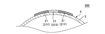
- the electrode part 21 is composed of a central part 21X and expansion parts 21Y and 21Y as in the honeycomb structure 500 shown in FIGS. It is preferable that the electrical resistivity of the central portion 21X of the 21 is smaller than the electrical resistivity of the extended portions 21Y and 21Y of the electrode portion 21.
- the central portion 21 ⁇ / b> X is a portion in the circumferential direction of the electrode portion 21 in a cross section orthogonal to the extending direction of the cell 2.
- the extended portions 21Y and 21Y are portions located on both sides in the circumferential direction of the central portion 21X in a cross section orthogonal to the extending direction of the cells 2.
- FIG. 4 is a front view schematically showing another embodiment of the honeycomb structure of the present invention.
- FIG. 5 is a schematic view showing a cross section perpendicular to the cell extending direction of another embodiment of the honeycomb structure of the present invention.
- the electrical resistivity of the central portion 21X is preferably 0.0001 to 70%, more preferably 0.001 to 50%, and particularly preferably 0.001 to 10% of the electrical resistivity of the extended portions 21Y and 21Y. If it is less than 0.0001%, the flow of current in the outer peripheral direction in the cross section perpendicular to the central axis of the honeycomb structure portion becomes small, and the deviation in temperature distribution may become large. If it is larger than 70%, the effect of suppressing the uneven temperature distribution of the honeycomb structure 400 may be reduced.
- the Young's modulus of the electrode portion 21 is preferably 2 to 50 GPa, more preferably 3 to 45 GPa, and particularly preferably 3 to 35 GPa.
- the Young's modulus of the electrode part 21 is preferably 2 to 50 GPa, more preferably 3 to 45 GPa, and particularly preferably 3 to 35 GPa.
- the Young's modulus may be uniform within the electrode portion 21 or may be partially different. When the Young's modulus is partially different, the above effect can be obtained if a part is within the above range, and the above effect is further enhanced if all are within the above range.
- the Young's modulus of the electrode part is a value measured by a bending resonance method in accordance with JIS R1602. As a test piece used for measurement, after a plurality of sheets made of electrode part forming raw materials for forming an electrode part were stacked to obtain a laminate, the laminate was dried and cut into a size of 3 mm ⁇ 4 mm ⁇ 40 mm. Use things.
- the electrode portion 21 is preferably mainly composed of silicon carbide particles and silicon, and more preferably formed from silicon carbide particles and silicon as raw materials except for impurities that are usually contained.
- “mainly composed of silicon carbide particles and silicon” means that the total mass of the silicon carbide particles and silicon is 90% by mass or more of the mass of the entire electrode portion.
- the component of the electrode part 21 and the component of the honeycomb structure part 4 are the same component or a close component (the material of the honeycomb structure part is silicon carbide). If there is). Therefore, the thermal expansion coefficients of the electrode part 21 and the honeycomb structure part 4 are the same value or close values.
- the bonding strength between the electrode part 21 and the honeycomb structure part 4 is also increased. Therefore, even when thermal stress is applied to the honeycomb structure, it is possible to prevent the electrode portion 21 from being peeled off from the honeycomb structure portion 4 and the joint portion between the electrode portion 21 and the honeycomb structure portion 4 being damaged.
- the electrode part 21 preferably has an average pore diameter of 5 to 45 ⁇ m, more preferably 7 to 40 ⁇ m.
- the average pore diameter of the electrode part 21 is in such a range, a suitable electrical resistivity can be obtained. If the average pore diameter of the electrode part 21 is smaller than 5 ⁇ m, the electrical resistivity may be too high. When the average pore diameter of the electrode part 21 is larger than 40 ⁇ m, the strength of the electrode part 21 is weakened and may be easily damaged.
- the average pore diameter is a value measured with a mercury porosimeter.
- the average particle diameter of the silicon carbide particles contained in the electrode part 21 is preferably 10 to 70 ⁇ m, and more preferably 10 to 60 ⁇ m. .
- the electrical resistivity of the electrode portion 21 can be controlled in the range of 0.1 to 100 ⁇ cm. If the average pore diameter of the silicon carbide particles contained in the electrode part 21 is smaller than 10 ⁇ m, the electrical resistivity of the electrode part 21 may become too large. When the average pore diameter of the silicon carbide particles contained in the electrode portion 21 is larger than 70 ⁇ m, the strength of the electrode portion 21 is weakened and may be easily damaged.
- the average particle diameter of the silicon carbide particles contained in the electrode part 21 is a value measured by a laser diffraction method.
- the ratio of the mass of silicon contained in the electrode part 21 to the “total of the respective masses of silicon carbide particles and silicon” contained in the electrode part 21 is preferably 20 to 50% by mass, and preferably 20 to 40%. More preferably, it is mass%.
- the electrical resistivity of electrode portion 21 is 0.1 to 100 ⁇ cm. Can be controlled by range. If the ratio of the mass of silicon to the total mass of silicon carbide particles and silicon contained in the electrode portion 21 is less than 20% by mass, the electrical resistivity may be too large. If it is larger than 50% by mass, it may be easily deformed during production.
- the partition wall thickness is 50 to 260 ⁇ m, and preferably 70 to 180 ⁇ m.
- the partition wall thickness is 50 to 260 ⁇ m, and preferably 70 to 180 ⁇ m.
- the honeycomb structure 100 of the present embodiment preferably has a cell density of 40 to 150 cells / cm 2 , and more preferably 70 to 100 cells / cm 2 .
- the purification performance of the catalyst can be enhanced while reducing the pressure loss when the exhaust gas is flowed.
- the cell density is lower than 40 cells / cm 2 , the catalyst supporting area may be reduced.
- the cell density is higher than 150 cells / cm 2 , when the honeycomb structure 100 is used as a catalyst carrier and a catalyst is supported, the pressure loss when the exhaust gas flows may increase.
- the average particle diameter of the silicon carbide particles (aggregate) constituting the honeycomb structure portion 4 is preferably 3 to 50 ⁇ m, and more preferably 3 to 40 ⁇ m.
- the electrical resistivity at 400 ° C. of the honeycomb structure part 4 can be 1 to 200 ⁇ cm.
- the electrical resistivity of the honeycomb structure portion 4 may be increased.
- the electrical resistivity of the honeycomb structure portion 4 may be reduced.
- the extrusion forming die may be clogged with the forming raw material when the honeycomb formed body is extruded.
- the average particle diameter of the silicon carbide particles is a value measured by a laser diffraction method.
- the electrical resistivity of the honeycomb structure portion 4 is 1 to 200 ⁇ cm, and preferably 40 to 100 ⁇ cm.
- the electrical resistivity is smaller than 1 ⁇ cm, for example, when the honeycomb structure 100 is energized by a high-voltage power supply of 200 V or higher, an excessive current may flow.
- the electrical resistivity is greater than 200 ⁇ cm, for example, when the honeycomb structure 100 is energized by a high-voltage power supply of 200 V or higher, it becomes difficult for current to flow, and heat generation may not occur sufficiently.
- the electrical resistivity of the honeycomb structure part is a value measured by a four-terminal method.
- the electrical resistivity of the honeycomb structure part is a value at 400 ° C.
- the electrical resistivity of the electrode portion 21 is lower than the electrical resistivity of the honeycomb structure portion 4. Furthermore, the electrical resistivity of the electrode portion 21 is more preferably 20% or less, and particularly preferably 1 to 10% of the electrical resistivity of the honeycomb structure portion 4. By setting the electrical resistivity of the electrode part 21 to 20% or less of the electrical resistivity of the honeycomb structure part 4, the electrode part 21 functions more effectively as an electrode.
- the “mass of silicon carbide particles” and the “mass of silicon” have the following relationship: Is preferred. That is, the ratio of “mass of silicon” to the total of “mass of silicon carbide particles” and “mass of silicon” is preferably 10 to 40% by mass, and more preferably 15 to 35% by mass. preferable. If it is lower than 10% by mass, the strength of the honeycomb structure may be lowered. If it is higher than 40% by mass, the shape may not be maintained during firing.
- the above “mass of silicon carbide particles” refers to “mass of silicon carbide particles as an aggregate” contained in the honeycomb structure portion 4.
- the above “mass of silicon” refers to “mass of silicon as a binder” contained in the honeycomb structure 4.
- the porosity of the partition walls 1 of the honeycomb structure portion 4 is preferably 35 to 60%, and more preferably 45 to 55%. If the porosity is less than 35%, deformation during firing may increase. When the porosity exceeds 60%, the strength of the honeycomb structure may be lowered.
- the porosity is a value measured with a mercury porosimeter.
- the average pore diameter of the partition walls 1 of the honeycomb structure part 4 is preferably 2 to 15 ⁇ m, and more preferably 4 to 8 ⁇ m. If the average pore diameter is smaller than 2 ⁇ m, the electrical resistivity may become too large. If the average pore diameter is larger than 15 ⁇ m, the electrical resistivity may be too small.
- the average pore diameter is a value measured with a mercury porosimeter.
- the shape of the cell 2 in a cross section perpendicular to the extending direction of the cell 2 is a quadrangle, a hexagon, an octagon, or a combination thereof.
- the shape of the honeycomb structure 100 of the present embodiment is not particularly limited.
- the bottom surface may have a circular cylindrical shape (cylindrical shape), the bottom surface may have an oval cylindrical shape, and the bottom surface may have a polygonal shape (square, pentagon, hexagon, heptagon, octagon, etc.). it can.
- the honeycomb structure has a bottom surface area of preferably 2000 to 20000 mm 2 , and more preferably 4000 to 10000 mm 2 .
- the length of the honeycomb structure in the central axis direction (cell extending direction) is preferably 50 to 200 mm, and more preferably 75 to 150 mm.
- the isostatic strength of the honeycomb structure 100 of the present embodiment is preferably 1 MPa or more, and more preferably 3 MPa or more. The larger the value of isostatic strength, the better. Considering the material and structure of the honeycomb structure 100, the upper limit is about 6 MPa. When the isostatic strength is less than 1 MPa, the honeycomb structure may be easily damaged when used as a catalyst carrier or the like. Isostatic strength is a value measured by applying hydrostatic pressure in water.
- the honeycomb structure 100 of the present embodiment has a pair of electrode portions 21 and 21 extending in the direction in which the cells 2 of the honeycomb structure portion 4 extend and “between both ends ( It is formed in a strip shape extending between both end faces 11 and 12).
- the pair of electrode portions 21 and 21 are disposed so as to extend between both ends of the honeycomb structure portion 4, so that when a voltage is applied between the pair of electrode portions 21 and 21, the honeycomb structure
- the bias of the current flowing through the portion 4 can be more effectively suppressed.
- the electrode portion 21 is formed (arranged) so as to extend between both end portions of the honeycomb structure portion 4” means that the following condition (X) is satisfied.
- Condition (X) is: “One end of the electrode part 21 is in contact with one end (one end face) of the honeycomb structure 4, and the other end of the electrode part 21 is the other end of the honeycomb structure 4. Part (the other end face) ".
- both end portions 21 a and 21 b of the electrode portion 21 in the “extending direction of the cells 2 of the honeycomb structure portion 4” are both end portions (both end surfaces 11 and 12 of the honeycomb structure portion 4). ) May not be in contact (not reached).
- one end portion 21 a of the electrode portion 21 is in contact with (reaches) one end portion (one end surface 11) of the honeycomb structure portion 4, and the other end portion 21 b is the other end of the honeycomb structure portion 4.
- the following distance D1 is from one end portion 21a of the remaining one electrode portion 21 of the pair of electrode portions 21 and 21 to "one end portion (one end surface 11) of the honeycomb structure portion 4".
- the distance is preferably the same, but may be different.
- the distance D1 is a distance from one end portion 21a of one electrode portion 21 of the pair of electrode portions 21 and 21 to "one end portion (one end surface 11) of the honeycomb structure portion 4".
- the following distance D2 is from the other end 21b of the remaining one electrode portion 21 of the pair of electrode portions 21 and 21 to the “other end portion (the other end surface 12) of the honeycomb structure portion 4”.
- the distance is preferably the same, but may be different.
- the distance D2 is a distance from the other end portion 21b of one electrode portion 21 of the pair of electrode portions 21 and 21 to "the other end portion (the other end face 12) of the honeycomb structure portion 4". It is.
- One end 21 a of the electrode portion 21 is an end facing the one end portion (one end surface 11) side of the honeycomb structure portion 4.
- the other end portion 21 b of the electrode portion 21 is an end portion facing the other end portion (the other end surface 12) side of the honeycomb structure portion 4.
- FIG. 9 is a perspective view schematically showing another embodiment (honeycomb structure 300) of the honeycomb structure of the present invention.
- each condition of the honeycomb structure 300 of the present embodiment is preferably the same as each condition in the embodiment (honeycomb structure 100) of the honeycomb structure of the present invention, except for the following condition (Y).
- the condition (Y) is “at least one end of the electrode portion 21 is not in contact with (has reached) the end (end surface) of the honeycomb structure 4”.
- the distance D3 is the length in the extending direction of the cells 2 of the honeycomb structure portion 4. It is preferably shorter than 50%, more preferably 25% or less. If it is 50% or more, when a voltage is applied between the pair of electrode parts 21 and 21, it may be difficult to suppress the bias of the current flowing in the honeycomb structure part 4.
- the distance D3 is a distance between “an end portion of the electrode portion 21” that is not in contact with the end portion (end surface) of the honeycomb structure portion 4 and “an end portion (end surface) of the honeycomb structure portion”.
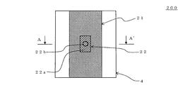
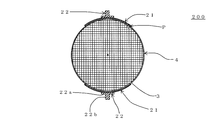
- the honeycomb structure 200 of the present embodiment is an electrode terminal protrusion 22 for connecting electric wirings in the honeycomb structure 100 of the present invention (see FIGS. 1 to 3). Is arranged.
- the electrode terminal protrusion 22 is a central portion of each electrode portion 21, 21 in the cross section perpendicular to the cell extending direction, and is disposed in the central portion in the cell extending direction.
- the electrode terminal protrusion 22 is a portion for connecting a wiring from a power source in order to apply a voltage between the electrode portions 21 and 21.
- FIG. 6 is a front view schematically showing still another embodiment of the honeycomb structure of the present invention.
- FIG. 7 is a schematic diagram showing an A-A ′ cross section in FIG. 6.
- Fig. 8 is a side view schematically showing still another embodiment of the honeycomb structure of the present invention.
- the conditions of the honeycomb structure 200 of the present embodiment are the same as the conditions in the embodiment of the honeycomb structure of the present invention (the honeycomb structure 100 (see FIGS. 1 to 3)) except for the following condition (Z). Preferably they are the same.
- the condition (Z) is “the electrode terminal for connecting the electric wiring to the center part of each electrode part 21, 21 in the cross section perpendicular to the extending direction of the cell 2 and to the center part in the extending direction of the cell 2.
- the protrusion 22 is disposed.
- the “central portion in the cross section perpendicular to the extending direction of the cells 2” refers to the central portion in the “peripheral direction of the honeycomb structure portion”.
- the main components of the electrode terminal protrusion 22 are also preferably silicon carbide particles and silicon.
- the electrode terminal protrusion 22 has silicon carbide particles and silicon as main components, the component of the electrode part 21 and the component of the electrode terminal protrusion 22 are the same (or close) components. Therefore, the thermal expansion coefficient of the electrode part 21 and the electrode terminal protrusion part 22 becomes the same (or close) value.
- the material of the electrode part 21 and the material of the electrode terminal protrusion part 22 become the same (or close), the joining strength of the electrode part 21 and the electrode terminal protrusion part 22 also becomes high.
- the electrode terminal protrusion 22 when “the electrode terminal protrusion 22 is composed mainly of silicon carbide particles and silicon”, the electrode terminal protrusion 22 contains 90% by mass or more of silicon carbide particles and silicon. Means that.
- the shape of the electrode terminal protrusion 22 is not particularly limited as long as it can be bonded to the electrode 21 and can be connected to the electric wiring.
- the electrode terminal protrusion 22 preferably has a shape in which a cylindrical protrusion 22b is disposed on a rectangular plate-like substrate 22a. With this shape, the electrode terminal protrusion 22 can be firmly bonded to the electrode portion 21 by the substrate 22a. Then, the electrical wiring can be reliably bonded by the protrusion 22b.
- the thickness of the substrate 22a is preferably 1 to 5 mm. By setting it as such thickness, the electrode terminal protrusion part 22 can be joined to the electrode part 21 reliably. If it is thinner than 1 mm, the substrate 22a becomes weak, and the protrusion 22b may be easily detached from the substrate 22a. If it is thicker than 5 mm, the space for arranging the honeycomb structure may become larger than necessary.
- the length (width) of the substrate 22 a is preferably 10 to 50%, more preferably 20 to 40% of the length of the electrode portion 21. By setting it as such a range, the electrode terminal protrusion part 22 becomes difficult to remove
- the “length (width) of the substrate 22a” is the length of the substrate 22a in the “peripheral direction in the cross section perpendicular to the cell extending direction of the honeycomb structure portion 4”.
- the “length of the electrode part 21” is the length of the electrode part 21 in “the outer peripheral direction (direction along the outer periphery) in the cross section of the honeycomb structure part 4 orthogonal to the cell extending direction”.
- the length of the substrate 22a in the “cell 2 extending direction” is preferably 5 to 30% of the length of the honeycomb structure 4 in the cell extending direction. By setting the length of the substrate 22a in the “direction in which the cells 2 extend” within such a range, sufficient bonding strength can be obtained. If the length of the substrate 22 a in the “cell 2 extending direction” is shorter than 5% of the length of the honeycomb structure portion 4 in the cell extending direction, the substrate 22 a may be easily detached from the electrode portion 21. And if it is longer than 30%, the mass may increase.
- the thickness of the protrusion 22b is preferably 3 to 15 mm. With such a thickness, the electrical wiring can be reliably bonded to the protrusion 22b. If it is thinner than 3 mm, the protrusion 22b may be easily broken. If it is thicker than 15 mm, it may be difficult to connect the electrical wiring.
- the length of the protrusion 22b is preferably 3 to 20 mm. With such a length, the electrical wiring can be reliably bonded to the protrusion 22b. If it is shorter than 3 mm, it may be difficult to join the electric wiring. If it is longer than 20 mm, the protrusion 22b may be easily broken.
- the electrical resistivity of the electrode terminal protrusion 22 is preferably 0.1 to 2.0 ⁇ cm, and more preferably 0.1 to 1.0 ⁇ cm. By setting the electrical resistivity of the electrode terminal protrusion 22 in such a range, current can be efficiently supplied from the electrode terminal protrusion 22 to the electrode portion 21 in the pipe through which high-temperature exhaust gas flows. If the electrical resistivity of the electrode terminal protrusion 22 is greater than 2.0 ⁇ cm, it may be difficult to supply current to the electrode portion 21 because current does not flow easily.
- the electrode terminal protrusion 22 preferably has a porosity of 30 to 45%, and more preferably 30 to 40%. When the porosity of the electrode terminal protrusion 22 is within such a range, an appropriate electrical resistivity can be obtained. If the porosity of the electrode terminal protrusion 22 is higher than 45%, the strength of the electrode terminal protrusion 22 may be reduced. In particular, when the strength of the protrusion 22b is lowered, the protrusion 22b may be easily broken.
- the porosity is a value measured with a mercury porosimeter.
- the electrode terminal protrusion 22 preferably has an average pore diameter of 5 to 20 ⁇ m, and more preferably 7 to 15 ⁇ m. When the average pore diameter of the electrode terminal protrusion 22 is within such a range, an appropriate electrical resistivity can be obtained. If the average pore diameter of the electrode terminal protrusion 22 is larger than 20 ⁇ m, the strength of the electrode terminal protrusion 22 may be reduced. In particular, when the strength of the protrusion 22b is lowered, the protrusion 22b may be easily broken.
- the average pore diameter is a value measured with a mercury porosimeter.
- the average particle diameter of the silicon carbide particles contained in the electrode terminal protrusion 22 is preferably 10 to 60 ⁇ m, and preferably 20 to 60 ⁇ m. More preferably.
- the electrical resistivity of the electrode terminal protrusion 22 can be set to 0.1 to 2.0 ⁇ cm. If the average pore diameter of the silicon carbide particles contained in the electrode terminal protrusion 22 is smaller than 10 ⁇ m, the electrical resistivity of the electrode terminal protrusion 22 may become too large.
- the average particle diameter of the silicon carbide particles contained in the electrode terminal protrusion 22 is a value measured by a laser diffraction method.
- the ratio of the mass of silicon contained in the electrode terminal projection 22 to the “total mass of silicon carbide particles and silicon” contained in the electrode terminal projection 22 is preferably 20 to 40% by mass. More preferably, the content is 25 to 35% by mass.
- an electrical resistivity of 0.1 to 2.0 ⁇ cm can be obtained. It becomes easy to obtain. If the ratio of the mass of silicon to the total mass of silicon carbide particles and silicon contained in the electrode terminal protrusion 22 is smaller than 20% by mass, the electrical resistivity may become too large. And when larger than 40 mass%, it may deform
- the honeycomb structure 400 (see FIG. 11) of the present embodiment is the same as the above-described embodiment of the honeycomb structure of the present invention (honeycomb structure 100 (see FIGS. 1 to 3)). It is installed on the surface of the electrode part 21.
- the conductor 23 has an electrical resistivity lower than the electrical resistivity of the electrode portion 21. Therefore, it is preferable that the honeycomb structure 400 of the present embodiment has the same conditions as the honeycomb structure 100 of the present invention (see FIGS. 1 to 3) except that the conductor 23 is included.
- FIG. 11 is a front view schematically showing still another embodiment of the honeycomb structure of the present invention.
- the conductor 23 having an electrical resistivity lower than that of the electrode portion 21 is provided on the surface of the electrode portion 21. Therefore, by applying a voltage to the conductor 23, it becomes possible to flow a current more uniformly through the entire honeycomb structure portion.
- the electrical resistivity of the conductor 23 is preferably 0.0001 to 70%, more preferably 0.001 to 50%, and particularly preferably 0.001 to 10% of the electrical resistivity of the electrode portion 21. If it is less than 0.0001%, the flow of current in the outer peripheral direction in the cross section perpendicular to the central axis of the honeycomb structure portion becomes small, and the deviation in temperature distribution may become large. If it is larger than 70%, the effect of suppressing the uneven temperature distribution of the honeycomb structure 400 may be reduced.
- the electrical resistivity is a value at 400 ° C.
- the shape (peripheral shape) of the conductor 23 is not particularly limited. As shown in FIG. 11, it is preferable that the electrode portion has a rectangular shape extending from one end portion 21a of the electrode portion to the other end portion 21b of the electrode portion.
- the conductor 23 may not extend between both end portions of the electrode portion. That is, there may be a gap between the end portion of the conductor 23 and the end portion of the electrode portion.
- the length of the conductor 23 is preferably 50% or more of the length of the electrode portion 21, more preferably 80% or more, and particularly preferably 100%. If it is shorter than 50%, when a voltage is applied, the effect of allowing a current to flow more uniformly through the entire honeycomb structure may be reduced.
- the “length of the conductor 23” is the length of the conductor 23 in the extending direction of the “cells of the honeycomb structure portion”.
- the “length of the electrode portion 21” is the length of the electrode portion 21 in the extending direction of the “cells of the honeycomb structure portion”.
- the length of the conductor 23 in the circumferential direction is not particularly limited as long as it is equal to or shorter than the length in the circumferential direction of the electrode portion.
- the circumferential length of the conductor 23 is preferably 5 to 75%, more preferably 10 to 60% of the circumferential length of the electrode portion. If it is longer than 75%, the temperature of the honeycomb structure near the both ends of the electrode portion 21 may easily rise in the cross section orthogonal to the cell extending direction. If it is shorter than 5%, when a voltage is applied, the effect of causing a current to flow more uniformly over the entire honeycomb structure may be reduced.
- Examples of the material for the conductor 23 include silicon carbide impregnated with silicon and a porosity of 5% or less.
- the thickness of the conductor 23 is preferably 0.1 to 2 mm, more preferably 0.2 to 1.5 mm, and particularly preferably 0.3 to 1 mm. If it is thicker than 2 mm, the thermal shock resistance of the honeycomb structure may be lowered. If it is thinner than 0.1 mm, the strength of the conductor 23 may be reduced.
- the honeycomb structure of the present invention can be used as a catalyst carrier.
- a known catalyst By supporting a known catalyst on the honeycomb structure of the present invention by a known method, it can be used as a catalyst for exhaust gas treatment.
- metal silicon powder metal silicon
- a binder a surfactant, a pore former, water and the like are added to silicon carbide powder (silicon carbide) to produce a forming raw material.
- the mass of the metal silicon is 10 to 40% by mass with respect to the total of the mass of the silicon carbide powder and the mass of the metal silicon.
- the average particle diameter of the silicon carbide particles in the silicon carbide powder is preferably 3 to 50 ⁇ m, and more preferably 3 to 40 ⁇ m.
- the average particle diameter of metal silicon (metal silicon powder) is preferably 2 to 35 ⁇ m.
- the average particle diameter of silicon carbide particles and metal silicon (metal silicon particles) is a value measured by a laser diffraction method.
- Silicon carbide particles are fine particles of silicon carbide constituting silicon carbide powder.
- the metal silicon particles are fine particles of metal silicon constituting the metal silicon powder. This is a composition of a forming raw material when the material of the honeycomb structure part is a silicon-silicon carbide based composite material. When the material of the honeycomb structure is silicon carbide, no metallic silicon is added.
- binder examples include methyl cellulose, hydroxypropyl methyl cellulose, hydroxypropoxyl cellulose, hydroxyethyl cellulose, carboxymethyl cellulose, and polyvinyl alcohol. Among these, it is preferable to use methyl cellulose and hydroxypropoxyl cellulose in combination.
- the content of the binder is preferably 2.0 to 10.0 parts by mass when the total mass of the silicon carbide powder and the metal silicon powder is 100 parts by mass.
- the water content is preferably 20 to 60 parts by mass when the total mass of the silicon carbide powder and the metal silicon powder is 100 parts by mass.
- ethylene glycol, dextrin, fatty acid soap, polyalcohol or the like can be used as the surfactant. These may be used individually by 1 type and may be used in combination of 2 or more type.
- the content of the surfactant is preferably 0.1 to 2.0 parts by mass when the total mass of the silicon carbide powder and the metal silicon powder is 100 parts by mass.
- the pore former is not particularly limited as long as it becomes pores after firing, and examples thereof include graphite, starch, foamed resin, water absorbent resin, silica gel and the like.
- the pore former content is preferably 0.5 to 10.0 parts by mass when the total mass of the silicon carbide powder and the metal silicon powder is 100 parts by mass.
- the average particle size of the pore former is preferably 10 to 30 ⁇ m. If it is smaller than 10 ⁇ m, pores may not be formed sufficiently. If it is larger than 30 ⁇ m, the die may be clogged during molding.
- the average particle diameter of the pore former is a value measured by a laser diffraction method.
- the forming raw material is kneaded to form a clay.
- molding raw material and forming a clay For example, the method of using a kneader, a vacuum clay kneader, etc. can be mentioned.
- the clay is extruded to form a honeycomb formed body.
- a die having a desired overall shape, cell shape, partition wall thickness, cell density and the like.
- a cemented carbide which does not easily wear is preferable.
- the honeycomb formed body has a structure having partition walls that form a plurality of cells that serve as fluid flow paths and an outer peripheral wall that is positioned on the outermost periphery.
- the partition wall thickness, cell density, outer peripheral wall thickness, etc. of the honeycomb molded body can be appropriately determined in accordance with the structure of the honeycomb structure of the present invention to be manufactured in consideration of shrinkage during drying and firing.
- the drying method is not particularly limited, and examples thereof include an electromagnetic heating method such as microwave heating drying and high-frequency dielectric heating drying, and an external heating method such as hot air drying and superheated steam drying. Among these, it is preferable to dry a certain amount of moisture by an electromagnetic heating method and then dry the remaining moisture by an external heating method. This is because the entire molded body can be dried quickly and uniformly without cracks. As drying conditions, it is preferable to remove 30 to 99% by mass of water with respect to the amount of moisture before drying by an electromagnetic heating method, and then to make the moisture to 3% by mass or less by an external heating method. . As the electromagnetic wave heating method, dielectric heating drying is preferable. As an external heating method, hot air drying is preferable.
- the length in the central axis direction of the honeycomb formed body is not a desired length, it is preferable to cut both end surfaces (both end portions) to a desired length.
- the cutting method is not particularly limited, and examples thereof include a method using a circular saw cutter.
- an electrode part forming raw material for forming the electrode part is prepared.
- the electrode part forming raw material is preferably formed by adding a predetermined additive to silicon carbide powder and silicon powder and kneading.
- a center part formation raw material and an expansion part formation raw material are each prepared.
- the central part forming raw material is preferably formed by adding predetermined additives to the silicon carbide powder and silicon powder and kneading.
- the extended portion forming raw material is preferably formed by adding a predetermined additive to the silicon carbide powder and the silicon powder and kneading.
- metal silicon powder metal silicon
- a binder a surfactant, a pore former, water and the like
- silicon carbide powder silicon carbide
- the mass of metal silicon is preferably 20 to 40 parts by mass.
- the average particle diameter of the silicon carbide particles in the silicon carbide powder is preferably 10 to 60 ⁇ m.
- the average particle diameter of the metal silicon powder (metal silicon) is preferably 2 to 20 ⁇ m. If it is smaller than 2 ⁇ m, the electrical resistivity may be too small. If it is larger than 20 ⁇ m, the electrical resistivity may become too large.
- the average particle diameter of silicon carbide particles and metal silicon (metal silicon particles) is a value measured by a laser diffraction method.
- Silicon carbide particles are fine particles of silicon carbide constituting silicon carbide powder.
- the metal silicon particles are fine particles of metal silicon constituting the metal silicon powder.
- binder examples include methyl cellulose, hydroxypropyl methyl cellulose, hydroxypropoxyl cellulose, hydroxyethyl cellulose, carboxymethyl cellulose, and polyvinyl alcohol. Among these, it is preferable to use methyl cellulose and hydroxypropoxyl cellulose in combination.
- the binder content is preferably 0.1 to 5.0 parts by mass when the total mass of the silicon carbide powder and the metal silicon powder is 100 parts by mass.
- the water content is preferably 15 to 60 parts by mass when the total mass of the silicon carbide powder and the metal silicon powder is 100 parts by mass.
- ethylene glycol, dextrin, fatty acid soap, polyalcohol or the like can be used as the surfactant. These may be used individually by 1 type and may be used in combination of 2 or more type.
- the content of the surfactant is preferably 0.1 to 2.0 parts by mass when the total mass of the silicon carbide powder and the metal silicon powder is 100 parts by mass.
- the pore former is not particularly limited as long as it becomes pores after firing, and examples thereof include graphite, starch, foamed resin, water absorbent resin, silica gel and the like.
- the pore former content is preferably 0.1 to 5.0 parts by mass when the total mass of the silicon carbide powder and the metal silicon powder is 100 parts by mass.
- the average particle size of the pore former is preferably 10 to 30 ⁇ m. If it is smaller than 10 ⁇ m, pores may not be formed sufficiently. When it is larger than 30 ⁇ m, air holes are easily formed, and the strength may be lowered.
- the average particle diameter of the pore former is a value measured by a laser diffraction method.
- a paste-like electrode part is formed by kneading a mixture obtained by mixing silicon carbide powder (silicon carbide), metal silicon (metal silicon powder), a binder, a surfactant, a pore former, water, and the like. It is preferable to use it as a raw material.
- the method of kneading is not particularly limited, and for example, a vertical stirrer can be used.
- the method for applying the electrode part forming raw material to the side surface of the honeycomb formed body is not particularly limited, and for example, a printing method can be used.
- the electrode part forming raw material is preferably applied to the side surface of the honeycomb molded body so as to have the shape and arrangement of the electrode part in the honeycomb structure of the present invention.
- the honeycomb part shown in FIG. 4 and FIG. 5 is provided on the side surface of the dried honeycomb formed body of the center part forming raw material and the extension part forming raw material.
- the structure 500 is preferably applied so as to have the shape of the central portion 21X and the extended portion 21Y of the electrode portion 21.
- the method for applying the central portion forming raw material and the extension portion forming raw material to the side surface of the honeycomb formed body is not particularly limited, and for example, a printing method can be used as in the case of applying the electrode portion forming raw material.
- the outer peripheral shape of the electrode part to be formed is the following shape. That is, it is a shape in which at least one corner of the rectangle is formed in a curved shape, or a shape in which at least one corner of the rectangle is chamfered in a straight line.
- the thickness of the electrode part can be set to a desired thickness by adjusting the thickness when the electrode part forming raw material is applied.
- an electrode part can be formed only by apply
- the electrode part forming raw material applied to the side surface of the honeycomb formed body it is preferable to dry.
- the drying conditions are preferably 50 to 100 ° C.
- the electrode terminal protrusion forming member is attached to the honeycomb formed body to become an electrode terminal protrusion.
- the shape of the electrode terminal protrusion forming member is not particularly limited, but for example, it is preferably formed in the shape as shown in FIGS. And it is preferable to affix the obtained electrode terminal protrusion part forming member to the part by which the electrode part formation raw material was apply
- the order of preparation of the honeycomb formed body, preparation of the electrode part forming raw material, and preparation of the electrode terminal protrusion forming member may be any order.
- the electrode terminal protrusion forming member is preferably obtained by molding and drying an electrode terminal protrusion forming raw material (a raw material for forming the electrode terminal protrusion forming member).
- the electrode terminal protrusion forming raw material is preferably formed by adding a predetermined additive to silicon carbide powder and silicon powder and kneading.
- a metal silicon powder (metal silicon), a binder, a surfactant, a pore former, water, etc. are added to silicon carbide powder (silicon carbide) and kneaded to prepare an electrode terminal protrusion forming raw material.
- the mass of the metal silicon is 20 to 40% by mass with respect to the total of the mass of the silicon carbide powder and the mass of the metal silicon.
- the average particle diameter of the silicon carbide particles in the silicon carbide powder is preferably 10 to 60 ⁇ m.
- the average particle diameter of the metal silicon powder (metal silicon) is preferably 2 to 20 ⁇ m. If it is smaller than 2 ⁇ m, the electrical resistivity may be too small.
- the average particle diameter of silicon carbide particles and metal silicon particles (metal silicon) is a value measured by a laser diffraction method.
- Silicon carbide particles are fine particles of silicon carbide constituting silicon carbide powder.
- the metal silicon particles are fine particles of metal silicon constituting the metal silicon powder.
- binder examples include methyl cellulose, hydroxypropyl methyl cellulose, hydroxypropoxyl cellulose, hydroxyethyl cellulose, carboxymethyl cellulose, and polyvinyl alcohol. Among these, it is preferable to use methyl cellulose and hydroxypropoxyl cellulose in combination.
- the content of the binder is preferably 2.0 to 10.0 parts by mass when the total mass of the silicon carbide powder and the metal silicon powder is 100 parts by mass.
- the water content is preferably 20 to 40 parts by mass when the total mass of the silicon carbide powder and the metal silicon powder is 100 parts by mass.
- ethylene glycol, dextrin, fatty acid soap, polyalcohol or the like can be used as the surfactant. These may be used individually by 1 type and may be used in combination of 2 or more type.
- the content of the surfactant is preferably 0.1 to 2.0 parts by mass when the total mass of the silicon carbide powder and the metal silicon powder is 100 parts by mass.
- the pore former is not particularly limited as long as it becomes pores after firing, and examples thereof include graphite, starch, foamed resin, water absorbent resin, silica gel and the like.
- the pore former content is preferably 0.1 to 5.0 parts by mass when the total mass of the silicon carbide powder and the metal silicon powder is 100 parts by mass.
- the average particle size of the pore former is preferably 10 to 30 ⁇ m. If it is smaller than 10 ⁇ m, pores may not be formed sufficiently. When it is larger than 30 ⁇ m, air holes are easily formed, and the strength may be lowered.
- the average particle diameter of the pore former is a value measured by a laser diffraction method.
- a mixture obtained by mixing silicon carbide powder (silicon carbide), metal silicon (metal silicon powder), a binder, a surfactant, a pore former, water, and the like is kneaded to obtain a material for forming electrode terminal protrusions. It is preferable that The method of kneading is not particularly limited, and for example, a kneader can be used.
- the method for forming the obtained electrode terminal protrusion forming raw material into the shape of the electrode terminal protrusion forming member is not particularly limited, and examples thereof include a method of processing after extrusion molding.
- the electrode terminal protrusion forming raw material into the shape of the electrode terminal protrusion forming member and then dry it to obtain the electrode terminal protrusion forming member.
- the drying conditions are preferably 50 to 100 ° C.
- the electrode terminal protrusion forming member is preferably attached to the honeycomb formed body coated with the electrode portion forming raw material.
- the method for attaching the electrode terminal protrusion forming member to the honeycomb formed body is not particularly limited. It is preferable that the electrode terminal protrusion forming member is attached to the honeycomb formed body using the electrode part forming raw material. For example, first, the electrode part forming raw material is applied to the “surface to be bonded to the honeycomb formed body (surface that contacts the honeycomb formed body)” of the electrode terminal protrusion forming member. Thereafter, the electrode terminal protrusion forming member is preferably attached to the honeycomb molded body so that the “surface coated with the electrode part forming raw material” is in contact with the honeycomb molded body.
- the “honeycomb formed body on which the electrode portion forming raw material is applied and the electrode terminal protrusion forming member is attached” it is preferable to dry and fire the “honeycomb formed body on which the electrode portion forming raw material is applied and the electrode terminal protrusion forming member is attached” to obtain the honeycomb structure of the present invention.
- the “dried honeycomb formed body” is fired by the following method, etc. May be performed.
- the above “dried honeycomb molded body” is the above “dried honeycomb molded body coated with the electrode part forming raw material (without the electrode terminal protrusion forming member attached)”. Treatments such as firing are provisional firing, firing, and oxidation treatment.
- the drying conditions at this time are preferably 50 to 100 ° C.
- pre-baking is preferably performed at 400 to 500 ° C. for 0.5 to 20 hours in an air atmosphere.
- the method of temporary baking and baking is not particularly limited, and baking can be performed using an electric furnace, a gas furnace, or the like.
- firing conditions it is preferable to heat at 1400 to 1500 ° C. for 1 to 20 hours in an inert atmosphere such as nitrogen or argon.
- oxygenation treatment it is preferable to perform oxygenation treatment at 1200 to 1350 ° C. for 1 to 10 hours after firing to improve durability.
- the electrode terminal protrusion forming member may be attached before firing the honeycomb formed body or may be attached after firing. When the electrode terminal protrusion forming member is attached after the honeycomb formed body is fired, it is preferably fired again under the above conditions.
- the conductor 23 is disposed without attaching the electrode terminal protrusion forming member. Is.
- the “dried honeycomb molded body” is a “honeycomb molded body coated with an electrode part forming raw material (without an electrode terminal protrusion forming member attached)” after drying.
- Example 1 Silicon carbide (SiC) powder and metal silicon (Si) powder were mixed at a mass ratio of 80:20. To this, hydroxypropylmethylcellulose as a binder and a water-absorbing resin as a pore former were added, and water was added to form a molding raw material. Thereafter, the forming raw material was kneaded with a vacuum kneader to produce a cylindrical clay. The content of the binder was 7 parts by mass when the total of silicon carbide (SiC) powder and metal silicon (Si) powder was 100 parts by mass. The content of the pore former was 3 parts by mass when the total of the silicon carbide (SiC) powder and the metal silicon (Si) powder was 100 parts by mass.
- the water content was 42 parts by mass when the total of silicon carbide (SiC) powder and metal silicon (Si) powder was 100 parts by mass.
- the average particle diameter of the silicon carbide powder was 20 ⁇ m.
- the average particle diameter of the metal silicon powder was 6 ⁇ m.
- the average particle diameter of the pore former was 20 ⁇ m.
- the average particle diameters of silicon carbide, metal silicon and pore former are values measured by a laser diffraction method.
- the obtained columnar kneaded material was molded using an extrusion molding machine to obtain a honeycomb molded body.
- the obtained honeycomb formed body was dried by high frequency dielectric heating. Then, it dried at 120 degreeC for 2 hours using the hot air dryer, and cut
- silicon carbide (SiC) powder and metal silicon (Si) powder were mixed at a mass ratio of 60:40.
- hydroxypropylmethylcellulose as a binder hydroxypropylmethylcellulose as a binder, glycerin as a humectant, a surfactant as a dispersant, and water were added and mixed.
- the mixture was kneaded to obtain an electrode part forming raw material.
- the content of the binder was 0.5 parts by mass when the total of silicon carbide (SiC) powder and metal silicon (Si) powder was 100 parts by mass.
- the content of glycerin was 10 parts by mass when the total of silicon carbide (SiC) powder and metal silicon (Si) powder was 100 parts by mass.
- the content of the surfactant was 0.3 parts by mass when the total of the silicon carbide (SiC) powder and the metal silicon (Si) powder was 100 parts by mass.
- the water content was 42 parts by mass when the total of silicon carbide (SiC) powder and metal silicon (Si) powder was 100 parts by mass.
- the average particle diameter of the silicon carbide powder was 52 ⁇ m.
- the average particle diameter of the metal silicon powder was 6 ⁇ m.
- the average particle diameter of silicon carbide and metal silicon is a value measured by a laser diffraction method. The kneading was performed with a vertical stirrer.
- the thickness (thickness after drying and firing) is 1.0 mm, “in the cross section perpendicular to the cell extending direction, the central angle is 0.
- the film was applied in the form of a band so that 5 times was 49.3 °.
- the electrode part forming raw material was applied to two sides of the dried honeycomb formed body. And, in the cross section orthogonal to the cell extending direction, one of the portions where the electrode part forming raw material is applied is arranged on the opposite side across the center of the honeycomb formed body with respect to the other. did.
- the shape (peripheral shape) of the electrode part forming raw material applied to the side surface of the honeycomb formed body was a rectangle. Then, the electrode part forming raw material was applied to the side surface of the honeycomb structure part so that the coating film made of the electrode part forming raw material extends between both ends of the honeycomb formed body.
- the electrode part forming raw material applied to the honeycomb formed body was dried.
- the drying conditions were 70 ° C.
- silicon carbide (SiC) powder and metal silicon (Si) powder were mixed at a mass ratio of 60:40.
- hydroxypropylmethylcellulose was added as a binder, and water was added and mixed.
- the mixture was kneaded to obtain an electrode terminal protrusion forming raw material.
- the electrode terminal protrusion forming raw material was made into clay using a vacuum kneader.
- the content of the binder was 4 parts by mass when the total of silicon carbide (SiC) powder and metal silicon (Si) powder was 100 parts by mass.
- the water content was 22 parts by mass when the total of silicon carbide (SiC) powder and metal silicon (Si) powder was 100 parts by mass.
- the average particle diameter of the silicon carbide powder was 52 ⁇ m.
- the average particle diameter of the metal silicon powder was 6 ⁇ m.
- the average particle diameter of silicon carbide and metal silicon is a value measured by a laser diffraction method.
- the obtained clay is processed into a shape like the electrode terminal protrusion 22 shown in FIGS. 6 to 8 (a shape composed of a substrate and a protrusion) and dried to form an electrode terminal protrusion forming member. Obtained.
- the drying conditions were 70 ° C.
- a portion corresponding to the plate-like substrate 22a was set to a size of “3 mm ⁇ 12 mm ⁇ 15 mm”.
- the portion corresponding to the protruding portion 22b was a columnar shape having a bottom surface diameter of 7 mm and a length in the central axis direction of 10 mm.
- Two electrode terminal protrusion forming members were produced.
- each of the two electrode terminal protrusion forming members was attached to each of the portions of the honeycomb formed body to which the electrode portion forming raw material was applied.
- the electrode terminal protrusion forming member was attached to the portion of the honeycomb formed body to which the electrode part forming raw material was applied using the electrode part forming raw material.
- “the honeycomb formed body on which the electrode part forming raw material was applied and the electrode terminal protrusion forming member was attached” was degreased, fired, and further oxidized to obtain a honeycomb structure.
- the degreasing conditions were 550 ° C. for 3 hours.
- the firing conditions were 1450 ° C. and 2 hours in an argon atmosphere.
- the conditions for the oxidation treatment were 1300 ° C. and 1 hour.
- the average pore diameter (pore diameter) of the partition walls of the obtained honeycomb structure was 8.6 ⁇ m, and the porosity was 45%.
- the average pore diameter and the porosity are values measured with a mercury porosimeter (manufactured by Micromeritics, Autopore IV9505).
- the honeycomb structure had a partition wall thickness of 101.6 ⁇ m and a cell density of 93 cells / cm 2 .
- the bottom surface of the honeycomb structure was a circle having a diameter of 93 mm, and the length of the honeycomb structure in the cell extending direction was 100 mm.
- the isostatic strength of the obtained honeycomb structure was 2.5 MPa. Isostatic strength is the breaking strength measured by applying hydrostatic pressure in water.
- the electrical resistivity of the electrode part was 0.8 ⁇ cm
- the electrical resistivity of the honeycomb structure part was 40 ⁇ cm
- the electrical resistivity of the electrode terminal protrusion was 0.8 ⁇ cm.
- the heat capacity of the electrode part of the obtained honeycomb structure (total heat capacity of the pair of electrode parts) was 7.9 J / gK.
- the heat capacity of the outer peripheral wall (whole) was 10.9 J / gK.
- the thickness of the electrode part was 0.4 mm and the thickness of the outer peripheral wall was 0.3 mm.
- the porosity of the electrode part was 40%, the Young's modulus of the electrode part was 29 GPa, and the porosity of the outer peripheral wall was 40%.
- the heat capacity of the electrode part is a value derived by a heat capacity calculation method taking into account the porosity, the specific gravity of the material, and the specific heat based on the volume of the electrode part.
- “Volume of electrode part” is the volume of the electrode part calculated using the average thickness of the electrode part and the electrode angle measured with an optical microscope.
- the heat capacity of the entire outer peripheral wall is a value derived by a heat capacity calculation method that takes into account the porosity, the specific gravity of the material, and the specific heat based on the volume of the outer peripheral wall.
- the “volume of the outer peripheral wall” is the volume of the outer peripheral wall calculated using the average thickness of the outer peripheral wall measured with an optical microscope.
- the thickness of an electrode part is the value of the average thickness of three points of the circumferential direction of the electrode part measured with the optical microscope.
- the thickness of the outer peripheral wall is a value of an average thickness at eight points in the circumferential direction of the outer peripheral wall measured with an optical microscope.
- the porosity of an electrode part and an outer peripheral wall is the value measured with the mercury porosimeter (The product made by Micromeritics, Autopore IV95505).
- the electrical resistivity of the honeycomb structure part, the electrode part, and the electrode terminal protrusion part was measured by the following method.
- a test piece of 10 mm ⁇ 10 mm ⁇ 50 mm was made of the same material as the measurement object. That is, when measuring the electrical resistivity of the honeycomb structure part, a test piece was made of the same material as that of the honeycomb structure part.
- a test piece was made of the same material as the electrode part.
- the test piece was produced with the same material as an electrode terminal protrusion part.
- a silver paste was applied to the entire surface of both ends (both ends in the longitudinal direction) of the test piece so that the wiring could be energized.
- a voltage application current measuring device was connected to the test piece and applied.
- a thermocouple was installed at the center of the test piece, and the time-dependent change in the test piece temperature during voltage application was confirmed with a recorder. 100 to 200 V was applied, and the current value and voltage value were measured at a test piece temperature of 400 ° C. The electrical resistivity was calculated from the obtained current value and voltage value, and the test piece size.
- the Young's modulus of the electrode part was measured by a bending resonance method in accordance with JIS R1602.
- a bulk body was prepared by using the raw material for forming the electrode portion, and the bulk body cut into a size of 3 mm ⁇ 4 mm ⁇ 40 mm (test piece) was used.
- the obtained honeycomb structure was measured for “temperature difference”, “thermal shock resistance” (crack), “resistance change”, and “maximum temperature” by the following methods.
- the results are shown in Table 1.
- the column “A / B” indicates the ratio (%) of the electrode thickness A to the outer peripheral wall thickness B.
- the column “C / D” indicates how many times the electrode porosity C is larger than the outer peripheral wall porosity D (times).
- E / F indicates the ratio (%) of the electrode portion heat capacity E to the outer peripheral wall heat capacity F.
- a heating / cooling test of the honeycomb structure was performed using a propane gas burner testing machine, and an evaluation test of a temperature difference in the honeycomb structure was performed at that time.
- the propane gas burner tester can supply a heating gas into a metal case that houses a honeycomb structure using a gas burner that burns propane gas.
- the obtained honeycomb structure was housed (canned) in a metal case of a propane gas burner testing machine.
- a gas heated by a gas burner was supplied into the metal case so that it passed through the honeycomb structure.
- the temperature condition of the heated gas flowing into the metal case was as follows. First, the temperature was raised to 950 ° C.
- the propane gas burner testing machine is capable of “supplying a heating gas using a gas burner that burns propane gas” into a metal case that houses a honeycomb structure.
- the evaluation test first, the obtained honeycomb structure was housed (canned) in a metal case of a propane gas burner testing machine.
- a gas heated by a gas burner was supplied into the metal case so that it passed through the honeycomb structure.
- the temperature condition of the heated gas flowing into the metal case was as follows. First, the temperature was raised to 950 ° C.
- “resistance change” was also evaluated according to the following evaluation criteria. If the difference in resistance value before and after the “thermal shock resistance” test is within 20% of the resistance value of the honeycomb structure before the “thermal shock resistance” test, the “resistance change” is “none”. The resistance change is “small” when the difference in resistance value exceeds 20% and less than 100% of the resistance value of the honeycomb structure before the “thermal shock resistance” test. When the difference in resistance value is 100% or more of the resistance value of the honeycomb structure before the “thermal shock resistance” test, the resistance change is “large”. This evaluation result is shown in the “resistance change (B)” column of Table 1. Evaluation based on the above evaluation criteria is referred to as “resistance change (B)”.
- the resistance value was measured by wiring the electrode terminal protrusions of the honeycomb structure and energizing them. During the measurement, a voltage application current measurement device was connected to the honeycomb structure and applied. A current value and a voltage value were measured by applying 100 to 200 V, and the honeycomb structure electric resistivity was calculated from the obtained current value and voltage value. The minimum resistance value during energization was taken as the resistance value (resistance) of the honeycomb structure. When a large crack occurs, the resistance value increases.
- the temperature of the honeycomb structure portion was measured when a voltage of 200 V was applied to the obtained honeycomb structure.
- “Temperature of the honeycomb structure portion” means that the “position at which the end portion of the electrode portion (the end portion in the circumferential direction) contacts with the center point in the circumferential direction of the electrode portion in the cross section perpendicular to the cell extending direction” It is the temperature at the “contact position”. The highest temperature among the measured temperatures was defined as the maximum temperature. In the honeycomb structure part, either the position where the end part (circumferential end part) of the electrode part touches or the position where the center point in the circumferential direction of the electrode part touches is the position where the most current flows. This is the highest temperature part. The position in the gas flow direction (temperature measurement position) was the center.
- Examples 2 to 23, Comparative Examples 1 to 7 The honeycomb structure was the same as in Example 1 except that the electrode thickness, outer peripheral wall thickness, electrode porosity, outer peripheral wall porosity, electrode heat capacity, and outer peripheral wall heat capacity were changed as shown in Table 1.
- a structure was produced.
- the “temperature difference”, “thermal shock resistance”, “resistance change”, and “maximum temperature” of the honeycomb structure were measured.
- “ ⁇ ” in the “temperature difference” column indicates that the test could not be performed.
- the test could not be performed because the obtained honeycomb structure could not be cannated (stored) in a metal case.
- the electrode thickness is large, a large local load is applied to the electrode portion during canning, so that it is in a state of being damaged when it is forcibly canned. The results are shown in Table 1.
- honeycomb structure is excellent in thermal shock resistance when the total heat capacity of the electrode portion is 2 to 150% of the heat capacity of the entire outer peripheral wall. It can also be seen that the honeycomb structures of Examples 1 to 23 have a low “maximum temperature”, whereas the honeycomb structures of Comparative Examples 1 to 7 have a very high “maximum temperature”.
- honeycomb structure of the present invention can be suitably used as a catalyst carrier for an exhaust gas purifying device that purifies exhaust gas from automobiles.
Landscapes
- Chemical & Material Sciences (AREA)
- Engineering & Computer Science (AREA)
- Ceramic Engineering (AREA)
- Chemical Kinetics & Catalysis (AREA)
- Toxicology (AREA)
- Health & Medical Sciences (AREA)
- Combustion & Propulsion (AREA)
- Mechanical Engineering (AREA)
- General Engineering & Computer Science (AREA)
- Materials Engineering (AREA)
- Structural Engineering (AREA)
- Organic Chemistry (AREA)
- Manufacturing & Machinery (AREA)
- Catalysts (AREA)
- Exhaust Gas Treatment By Means Of Catalyst (AREA)
- Exhaust Gas After Treatment (AREA)
- Porous Artificial Stone Or Porous Ceramic Products (AREA)
- Ceramic Products (AREA)
Abstract
複数のセル2を区画形成する多孔質の隔壁1と外周壁3とを有する筒状のハニカム構造部4と、ハニカム構造部4の側面5に配設された一対の電極部21とを備え、ハニカム構造部4の電気抵抗率が1~200Ωcmであり、一対の電極部21のそれぞれが、セル2の延びる方向に延びる帯状に形成され、セル2の延びる方向に直交する断面において、一方の電極部21が他方の電極部21に対して、ハニカム構造部4の中心を挟んで反対側に配設され、一対の電極部21の熱容量の合計が、外周壁3全体の熱容量の2~150%であるハニカム構造体100。触媒担体であると共に電圧を印加することによりヒーターとしても機能し、更に耐熱衝撃性に優れたハニカム構造体を提供する。
Description
本発明は、ハニカム構造体に関する。さらに詳しくは、触媒担体であると共に電圧を印加することによりヒーターとしても機能し、更に耐熱衝撃性に優れたハニカム構造体に関する。
従来、コージェライト製のハニカム構造体に触媒を担持したものを、自動車エンジンから排出された排ガス中の有害物質の処理に用いていた。また、炭化珪素質焼結体によって形成されたハニカム構造体を排ガスの浄化に使用することも知られている(例えば、特許文献1を参照)。
ハニカム構造体に担持した触媒によって排ガスを処理する場合、触媒を所定の温度まで昇温する必要がある。しかし、エンジン始動時には、触媒温度が低いため、排ガスが十分に浄化されないという問題があった。
そのため、触媒が担持されたハニカム構造体の上流側に、金属製のヒーターを設置して、排ガスを昇温させる方法が検討されている(例えば、特許文献2を参照)。
また、導電性セラミックスからなり両端部に電極が配設されたハニカム構造体を、ヒータ付触媒担体として使用することが開示されている(例えば、特許文献3を参照)。
上記のような金属製のヒーターを、自動車に搭載して使用する場合、自動車の電気系統に使用される電源が共通で使用される。そのため、例えば、200Vという高い電圧の電源が用いられる。しかし、金属製のヒーターは、電気抵抗が低い。そのため、上記のような高い電圧の電源を用いた場合、過剰に電流が流れ、電源回路を損傷させることがあるという問題があった。
また、ヒーターが金属製であると、仮にハニカム構造に加工したものであっても、触媒を担持し難い。そのため、ヒーターと触媒とを一体化させることは難しかった。
また、導電性セラミックスからなるハニカム構造体の両端部に電極を配設したヒーター付触媒担体は、電極が劣化し易く、抵抗値が上昇することがあった。これは、当該ヒーター付触媒担体を自動車に搭載して使用する際に、電極が、排ガスに直接暴露されるためであった。
本発明は、上述した問題に鑑みてなされたものであり、触媒担体であると共に電圧を印加することによりヒーターとしても機能し、更に耐熱衝撃性に優れたハニカム構造体を提供することを目的とする。
上述の課題を解決するため、本発明は、以下のハニカム構造体を提供する。
[1] 流体の流路となる一方の端面から他方の端面まで延びる複数のセルを区画形成する多孔質の隔壁と最外周に位置する外周壁とを有する筒状のハニカム構造部と、前記ハニカム構造部の側面に配設された一対の電極部とを備え、前記ハニカム構造部の電気抵抗率が、1~200Ωcmであり、前記一対の電極部のそれぞれが、前記ハニカム構造部のセルの延びる方向に延びる帯状に形成され、前記セルの延びる方向に直交する断面において、前記一対の電極部における一方の前記電極部が、前記一対の電極部における他方の前記電極部に対して、前記ハニカム構造部の中心を挟んで反対側に配設され、前記一対の電極部の熱容量の合計が、外周壁全体の熱容量の2~150%であるハニカム構造体。
[2] 前記一対の電極部の熱容量の合計が、外周壁全体の熱容量の2~80%である[1]に記載のハニカム構造体。
[3] 前記一対の電極部の厚さが、0.025~1.0mmである[1]又は[2]に記載のハニカム構造体。
[4] 前記一対の電極部の気孔率が、30~80%である[1]又は[2]に記載のハニカム構造体。
[5] 前記電極部の電気抵抗率が、0.01~100Ωcmである[1]~[4]のいずれかに記載のハニカム構造体。
[6] 前記電極部の電気抵抗率よりも低い電気抵抗率をもつ導電体が、前記電極部の表面に設置された[1]~[5]のいずれかに記載のハニカム構造体。
本発明のハニカム構造体は、ハニカム構造部の電気抵抗率が1~200Ωcmである。そのため、電圧の高い電源を用いて電流を流しても、過剰に電流が流れず、ヒーターとして好適に用いることができる。また、本発明のハニカム構造体は、一対の電極部のそれぞれが、ハニカム構造部のセルの延びる方向に延びる帯状に形成されている。そして、本発明のハニカム構造体は、セルの延びる方向に直交する断面において、一対の電極部における一方の電極部が、一対の電極部における他方の電極部に対して、ハニカム構造部の中心を挟んで反対側に配設される。そのため、本発明のハニカム構造体は、電圧を印加したときの温度分布の偏りを抑制することができる。更に、本発明のハニカム構造体は、一対の電極部の熱容量の合計が、外周壁全体の熱容量の2~150%である。そのため、本発明のハニカム構造体は、ハニカム構造体を内燃機関の排気システムに搭載して使用した際に、急激な温度変化があっても、ハニカム構造部に大きな応力が生じることを抑制することができる。これにより、ハニカム構造体にクラックが生じることを抑制することができる。
次に本発明を実施するための形態を図面を参照しながら詳細に説明するが、本発明は以下の実施形態に限定されるものではなく、本発明の趣旨を逸脱しない範囲で、当業者の通常の知識に基づいて、適宜設計の変更、改良等が加えられることが理解されるべきである。
(1)ハニカム構造体:
本発明のハニカム構造体の一の実施形態は、図1~図3に示すハニカム構造体100のように、多孔質の隔壁1と最外周に位置する外周壁3とを有する筒状のハニカム構造部4と、ハニカム構造部4の側面5に配設された一対の電極部21,21とを備えている。隔壁1は、「流体の流路となる、一方の端面11から他方の端面12まで延びる」複数のセル2を区画形成するものである。ハニカム構造体100は、ハニカム構造部4の電気抵抗率が、1~200Ωcmである。ハニカム構造体100の一対の電極部21,21のそれぞれは、ハニカム構造部4のセル2の延びる方向に延びる帯状に形成されている。そして、ハニカム構造体100は、セル2の延びる方向に直交する断面において、一対の電極部21,21における一方の電極部21が、一対の電極部21,21における他方の電極部21に対して、ハニカム構造部4の中心Oを挟んで反対側に配設されている。更に、ハニカム構造体100は、一対の電極部21,21の熱容量の合計が、外周壁3全体の熱容量の2~150%のものである。図1は、本発明のハニカム構造体の一の実施形態を模式的に示す斜視図である。図2は、本発明のハニカム構造体の一の実施形態の、セルの延びる方向に平行な断面を示す模式図である。図3は、本発明のハニカム構造体の一の実施形態の、セルの延びる方向に直交する断面を示す模式図である。尚、図3においては、隔壁が省略されている。
本発明のハニカム構造体の一の実施形態は、図1~図3に示すハニカム構造体100のように、多孔質の隔壁1と最外周に位置する外周壁3とを有する筒状のハニカム構造部4と、ハニカム構造部4の側面5に配設された一対の電極部21,21とを備えている。隔壁1は、「流体の流路となる、一方の端面11から他方の端面12まで延びる」複数のセル2を区画形成するものである。ハニカム構造体100は、ハニカム構造部4の電気抵抗率が、1~200Ωcmである。ハニカム構造体100の一対の電極部21,21のそれぞれは、ハニカム構造部4のセル2の延びる方向に延びる帯状に形成されている。そして、ハニカム構造体100は、セル2の延びる方向に直交する断面において、一対の電極部21,21における一方の電極部21が、一対の電極部21,21における他方の電極部21に対して、ハニカム構造部4の中心Oを挟んで反対側に配設されている。更に、ハニカム構造体100は、一対の電極部21,21の熱容量の合計が、外周壁3全体の熱容量の2~150%のものである。図1は、本発明のハニカム構造体の一の実施形態を模式的に示す斜視図である。図2は、本発明のハニカム構造体の一の実施形態の、セルの延びる方向に平行な断面を示す模式図である。図3は、本発明のハニカム構造体の一の実施形態の、セルの延びる方向に直交する断面を示す模式図である。尚、図3においては、隔壁が省略されている。
このように、本実施形態のハニカム構造体100は、ハニカム構造部4の電気抵抗率が1~200Ωcmである。そのため、電圧の高い電源を用いて電流を流しても、過剰に電流が流れず、ヒーターとして好適に用いることができる。また、ハニカム構造体100は、一対の電極部21,21のそれぞれが、帯状に形成され、一方の電極部21が、他方の電極部21に対して、ハニカム構造部4の中心を挟んで反対側に配設されている。そのため、一対の電極部21,21間に電圧を印加したときの、ハニカム構造部4の温度分布の偏りを抑制することができる。更に、ハニカム構造体100は、一対の電極部21,21の熱容量の合計が、外周壁3全体の熱容量の2~150%である。そのため、急加熱、急冷却があったときに、ハニカム構造部4に大きな応力が生じることを抑制することができる。
尚、「セル2の延びる方向に直交する断面において、一対の電極部21,21における一方の電極部21が、一対の電極部21,21における他方の電極部21に対して、ハニカム構造部4の中心Oを挟んで反対側に配設される」は、以下のように定義される。即ち、セル2の延びる方向に直交する断面において、線分(A)と線分(B)とにより形成される角度βが、170°~190°の範囲となるような位置関係になるように、一対の電極部21,21がハニカム構造部4に配設されていることを意味する。上記線分(A)は、一方の電極部21の中央点(「ハニカム構造部4の周方向」における中央の点)とハニカム構造部4の中心Oとを結ぶ線分のことである。上記線分(B)は、他方の電極部21の中央点(「ハニカム構造部4の周方向」における中央の点)とハニカム構造部4の中心Oとを結ぶ線分のことである。角度βは、「中心O」を中心とする角度のことである。
本実施形態のハニカム構造体100においては、隔壁1及び外周壁3の材質が、珪素-炭化珪素複合材又は炭化珪素材を主成分とするものであることが好ましく、珪素-炭化珪素複合材又は炭化珪素材であることが更に好ましい。「隔壁1及び外周壁3の材質が、珪素-炭化珪素複合材又は炭化珪素材を主成分とするものである」というときは、隔壁1及び外周壁3が、珪素-炭化珪素複合材又は炭化珪素材を、全体の90質量%以上含有していることを意味する。このような材質を用いることにより、ハニカム構造部の電気抵抗率を1~200Ωcmにすることができる。ここで、珪素-炭化珪素複合材は、骨材としての炭化珪素粒子、及び炭化珪素粒子を結合させる結合材としての珪素を含有するものである。複数の炭化珪素粒子は、炭化珪素粒子間に細孔を形成するようにして、珪素によって結合されていることが好ましい。また、炭化珪素材は、炭化珪素粒子同士が焼結したものである。ハニカム構造部の電気抵抗率は、400℃における値である。
図1~図3に示されるように、本実施形態のハニカム構造体100は、ハニカム構造部4の側面5(外周壁3の表面)に一対の電極部21,21が配設されている。本実施形態のハニカム構造体100は、一対の電極部21,21間に電圧を印加することにより、発熱する。印加する電圧は12~900Vが好ましく、64~600Vが更に好ましい。
図1~図3に示されるように、本実施形態のハニカム構造体100は、(i)一対の電極部21,21のそれぞれが、ハニカム構造部4のセル2の延びる方向に延びる帯状に形成されている。そして、(ii)セル2の延びる方向に直交する断面において、一対の電極部21,21における一方の電極部21が、一対の電極部21,21における他方の電極部21に対して、ハニカム構造部4の中心部Oを挟んで反対側に配設されている。本実施形態のハニカム構造体100は、更に、中心角αの0.5倍が、15~65°であることが好ましく、30~60°であることが更に好ましい。中心角αは、セル2の延びる方向に直交する断面における、それぞれの電極部21,21の中心角のことである。中心角αの0.5倍とは、中心角αの0.5倍の角度θのことである。このように、上記(i)のようにするとともに、上記(ii)のようにし、更に、セル2の延びる方向に直交する断面において、それぞれの電極部21,21の中心角αの0.5倍の角度θを、15~65°とする。このようにすることにより、一対の電極部21,21間に電圧を印加した時に、ハニカム構造部4内を流れる電流の偏りを、より効果的に抑制することができる。別言すれば、ハニカム構造部4内を流れる電流を、より均一に流すことができる。これによりハニカム構造部4内の発熱の偏りを抑制することができる。「電極部21の中心角α」は、図3に示されるように、セル2の延びる方向に直交する断面において、電極部21の両端とハニカム構造部4の中心Oとを結ぶ2本の線分により形成される角度である。上記「2本の線分により形成される角度」とは、セル2の延びる方向に直交する断面において、電極部21と線分(a)と線分(b)とにより形成される形状(例えば、扇形)における、中心Oの部分の内角のことである。上記線分(a)は、電極部21の一方の端部と中心Oとを結ぶ線分のことである。上記線分(b)は、電極部21の他方の端部と中心Oとを結ぶ線分のことである。
また、一方の電極部21の「中心角αの0.5倍の角度θ」は、他方の電極部21の「中心角αの0.5倍の角度θ」に対して、0.8~1.2倍の大きさであることが好ましく、1.0倍の大きさ(同じ大きさ)であることが更に好ましい。これにより、一対の電極部21,21間に電圧を印加した時に、ハニカム構造部4内を流れる電流の偏りを、より効果的に抑制することができる。その結果、ハニカム構造部4内の発熱の偏りを、より効果的に抑制することができる。
本実施形態のハニカム構造体においては、例えば、図1~図3に示されるように、電極部21は、平面状の長方形の部材を、円筒形状の外周に沿って湾曲させたような形状となっている。ここで、湾曲した電極部21を、湾曲していない平面状の部材になるように変形したときの形状を、電極部21の「平面形状」と称することにする。上記、図1~図3に示される電極部21の「平面形状」は、長方形になる。そして、「電極部の外周形状」というときは、「電極部の平面形状における外周形状」を意味する。
本実施形態のハニカム構造体においては、図1~図3に示されるように、帯状の電極部21の外周形状が長方形であってもよい。本実施形態のハニカム構造体においては、帯状の電極部21の外周形状が、「長方形の角部が曲線状に形成された形状」であることも好ましい態様である。また、帯状の電極部21の外周形状が、「長方形の角部が直線状に面取りされた形状」であることも好ましい態様である。「曲線状」と「直線状」の複合適用も好ましい。即ち、帯状の電極部21の外周形状が、長方形において、角部の少なくとも一つが「曲線状に形成された形状」となっており、且つ、角部の少なくとも一つが「直線状に面取りされた形状」となっている形状であることも好ましい。また、本明細書における「帯状」は、シート状または膜状ということもできる。つまり、本明細書における「電極部」は、本明細書における「電極端子突起部」のように外側に向かって突出したものを含まない。
このように、電極部21の外周形状が、「長方形の角部が曲線状に形成された形状」、又は「長方形の角部が直線状に面取りされた形状」であることにより、ハニカム構造体の耐熱衝撃性を更に向上させることができる。電極部の角部が直角であると、ハニカム構造部における「当該電極部の角部」付近の応力が、他の部分と比較して相対的に高くなる傾向にある。これに対し、電極部の角部を曲線状にしたり直線状に面取りしたりすると、ハニカム構造部における「当該電極部の角部」付近の応力を低下させることが可能となる。
また、本実施形態のハニカム構造体においては、電極部が、「「内角が90°未満」の角部」を有さないことが好ましい。電極部が、「「内角が90°未満」の角部」を有すると、ハニカム構造体に熱衝撃を与えたときに、当該電極部の「「内角が90°未満」の角部」付近において、ハニカム構造部に高い応力がかかり易いためである。
本発明のハニカム構造体は、筒状のハニカム構造部の側面に一対の電極部を配設している。このように一対の電極部を配設することにより、ハニカム構造部のセルの延びる方向に直交する方向(又は、直交する方向に近い方向)に電流が流れるようにしている。このような、「ハニカム構造部の側面に電極部を配設する構造」においては、ハニカム構造部の側面に電極部が配設されている。そのため、外周壁における電極部が配設されている部分に熱が溜まり、外周壁における電極部が配設されていない部分との間に温度差が生じ易くなる。そのため、ハニカム構造体の耐熱衝撃性が低下する可能性があった。
本実施形態のハニカム構造体は、一対の電極部の熱容量の合計を、外周壁全体の熱容量の2~150%にしている。このような範囲とすることにより、電極部に蓄積する熱量が少なくなり、ハニカム構造体の耐熱衝撃性が向上する。そのため、ハニカム構造体を内燃機関の排気システムに搭載して使用した際に、急激な温度変化があっても、ハニカム構造部に大きな応力が生じることを抑制することができる。一対の電極部の熱容量の合計は、外周壁全体の熱容量以下にすること(即ち、2~100%であること)が好ましく、外周壁全体の熱容量より小さくすることが更に好ましい。これにより、電極部に蓄積する熱量が更に少なくなり、ハニカム構造体の耐熱衝撃性が更に向上する。そのため、ハニカム構造体を内燃機関の排気システムに搭載して使用した際に、急激な温度変化があっても、ハニカム構造部に大きな応力が生じることを更に抑制することができる。一対の電極部の熱容量の合計は、電極部の体積をもとに、気孔率、材料の比重、及び比熱を考慮した熱容量計算の方法で導き出した値である。上記「電極部の体積」は、光学顕微鏡で測定された電極部の平均厚みと電極角度(図3における、中心角α)とを用いて計算された電極部の体積のことである。外周壁全体の熱容量は、外周壁の体積をもとに、気孔率、材料の比重、及び比熱を考慮した熱容量計算の方法で導き出した値である。上記「外周壁の体積」は、光学顕微鏡で測定された外周壁の平均厚みを用いて計算された外周壁の体積のことである。尚、本明細書において、電極部が、ハニカム構造部の側面と接触している部分の面積を「電極部の接触面積」とする。また、ハニカム構造部と同軸であり電極部を分割する円筒を仮定し、その円筒に分割された電極部の分割面を仮想分割面とする。更に、この仮想分割面の面積を「仮想分割面積」とする。帯状の電極部と後述する「電極端子突起部」のように外側に向かって突出したものとの境界が明確でない場合、本明細書における「電極部の熱容量」の算出に際しては、上記「仮想分割面積」が、上記「電極部の接触面積」の90%以上となる部分を「電極部」とする。即ち、上記の場合、本明細書における「電極部の熱容量」の算出に際しては、上記「仮想分割面積」が、上記「電極部の接触面積」の90%未満となる部分は電極部ではないものとする。
本実施形態のハニカム構造体においては、「一対の電極部の熱容量の合計が、外周壁全体の熱容量より小さい」場合、具体的には、一対の電極部の熱容量の合計が、外周壁全体の熱容量の2~80%であることが好ましい。下限値は、9%であることが更に好ましく、15%であることが特に好ましい。また、上限値は、75%であることが更に好ましく、50%であることが特に好ましい。2%より小さいと、「電圧を印加したときに、ハニカム構造部の全体に、より均一に電流を流す」という効果が低下することがある。80%より大きいと、耐熱衝撃性を低下させる効果が小さくなることがある。
本実施形態のハニカム構造体においては、一対の電極部の厚さが、ハニカム構造部の外周壁の厚さの5~200%であることが好ましく、5~140%であることが更に好ましく、5~100%であることが特に好ましい。電極部の厚さと、ハニカム構造部の外周壁の厚さとの関係をこのようにすることにより、電極部の熱容量を、ハニカム構造部の外周壁の熱容量より低くすることができる。そのため、ハニカム構造体の耐熱衝撃性を向上させることができる。電極部の厚さが、ハニカム構造部の外周壁の厚さの5%より薄いと、ハニカム構造部に均一に電流を流すことが難しくなることがある。電極部の厚さが、ハニカム構造部の外周壁の厚さの200%より厚いと、電極部の熱容量を低くし難くなることがある。
電極部の厚さは、光学顕微鏡で測定された値である。具体的には、「セルの延びる方向おけるハニカム構造体の中央部」における、電極部の周方向3点の平均厚みの値である。「電極部の周方向3点の平均厚みの値」とは、以下のように定義される値である。即ち、電極部を「ハニカム構造部の周方向」に3等分して3つの分割部分を形成し、各分割部分において「ハニカム構造部の周方向」における中央部の厚さを測定し、得られた3点の厚さの測定結果を平均した値である。上記「電極部を「ハニカム構造部の周方向」に3等分」するとは、セルの延びる方向に平行な直線で、電極部を3等分することである。
ハニカム構造部の外周壁の厚さは、光学顕微鏡で測定された値である。具体的には、「セルの延びる方向おけるハニカム構造体の中央部」における、外周壁の周方向8点の平均厚みの値である。「外周壁の周方向8点」とは、以下のように定義される。即ち、図12に示されるように、ハニカム構造部4の「セルの延びる方向に直交する断面」において、直線L1、直線L2、直線L3、及び直線L4の4本の直線がハニカム構造部4の外周壁3と交差する8点のことである。直線L1は、中心Oを通り一の隔壁に平行な直線のことである。直線L2は、中心Oを通り直線L1との角度が45°となる直線のことである。直線L3は、中心Oを通り直線L2との角度が45°となる(直線L1との角度が90°となる)直線のことである。直線L4は、中心Oを通り直線L3との角度が45°となる(直線L2との角度が90°となる)直線のことである。尚、外周壁3の厚さを測定する際には、外周壁3と隔壁とが当接していない部分を測定する。従って、上記周方向8点のいずれかが、外周壁3と隔壁とが当接する部分となる場合には、その点から最も近い「外周壁3における隔壁が接続されていない部分」を測定する。図12は、本発明のハニカム構造体の一の実施形態(ハニカム構造体100)の、セルの延びる方向に直交する断面を示す模式図である。尚、図12のハニカム構造体100においては、電極部は省略されている。
本実施形態のハニカム構造体においては、一対の電極部の厚さが、0.025~1.0mmであることが好ましく、0.025~0.7mmであることが更に好ましく、0.05~0.5mmであることが特に好ましい。このように電極部の厚さを薄くすることにより、電極部の熱容量を低くすることができる。そのため、ハニカム構造体の耐熱衝撃性を向上させることができる。電極部の厚さが0.025mmより薄いと、ハニカム構造部に均一に電流を流すことが難しくなることがある。電極部の厚さが1.0mmより厚いと、電極部の熱容量を低くし難くなることがある。また、上記「電極部の厚さと、ハニカム構造部の外周壁の厚さとの好ましい関係(比率)」を満たすと共に、上記「電極部の厚さの好ましい範囲」を満たすことが、特に好ましい。
本実施形態のハニカム構造体においては、ハニカム構造部の外周壁の厚さが0.1~1.0mmであることが好ましく、0.2~0.8mmであることが更に好ましく、0.2~0.5mmであることが特に好ましい。ハニカム構造部の外周壁の厚さをこのような範囲にすることにより、ハニカム構造体の耐熱衝撃性を向上させることができる。また、これにより、ハニカム構造体を触媒担体として用いて、触媒を担持しても、排ガスを流したときの圧力損失が大きくなり過ぎることを抑制できる。ハニカム構造部の外周壁の厚さが0.1mmより薄いと、ハニカム構造体の強度が低下することがある。ハニカム構造部の外周壁の厚さが1.0mmより厚いと、ハニカム構造体の耐熱衝撃性が低下することがある。また、ハニカム構造部の外周壁の厚さが1.0mmより厚いと、ハニカム構造体を触媒担体として用いて、触媒を担持した場合に、触媒を担持する隔壁の面積が小さくなることがある。
本実施形態のハニカム構造体においては、下記条件(V)を満たすときには、一対の電極部の気孔率が、ハニカム構造部の外周壁の気孔率の0.75~2倍であることが好ましい。条件(V)は、「一対の電極部の厚さが、ハニカム構造部の外周壁の厚さの5~200%であり、且つ、一対の電極部の厚さが、0.025~1.0mmである」である。また、このとき、一対の電極部の気孔率が、30~80%であることが好ましい。これにより、ハニカム構造体の耐熱衝撃性を向上させると共に、電流を均一に流すという効果を、より効果的に発揮することができる。
本実施形態のハニカム構造体においては、一対の電極部の気孔率が、ハニカム構造部の外周壁の気孔率の0.75~2倍であることが好ましく、1~2倍であることが更に好ましく、1~1.75倍であることが特に好ましい。電極部の気孔率と、ハニカム構造部の外周壁の気孔率との関係をこのようにすることにより、電極部の熱容量を、ハニカム構造部の外周壁の熱容量より低くすることができる。そのため、ハニカム構造体の耐熱衝撃性を向上させることができる。電極部の気孔率が、ハニカム構造部の外周壁の気孔率の0.75倍より小さいと、電極部の熱容量を、外周壁の熱容量よりも低くすることが難しくなることがある。電極部の気孔率が、ハニカム構造部の外周壁の気孔率の2倍より大きいと、ハニカム構造部に均一に電流を流すことが難しくなることがある。電極部及び外周壁の気孔率は、水銀ポロシメータで測定した値である。
本実施形態のハニカム構造体においては、一対の電極部の気孔率が、30~80%であることが好ましく、30~70%であることが更に好ましく、30~60%であることが特に好ましい。電極部の気孔率がこのような範囲であることにより、電極部の熱容量を低くすることができる。そのため、ハニカム構造体の耐熱衝撃性を向上させることができる。電極部の気孔率が30%より小さいと、電極部の熱容量を低くし難くなることがある。電極部の気孔率が80%より大きいと、ハニカム構造部に均一に電流を流すことが難しくなることがある。また、電極部の気孔率が80%より大きいと、電極部の電気抵抗率が高くなり過ぎることがある。また、上記「電極部の気孔率と、ハニカム構造部の外周壁の気孔率との好ましい関係(比率)」を満たすと共に、上記「電極部の気孔率の好ましい範囲」を満たすことが、特に好ましい。
本実施形態のハニカム構造体においては、ハニカム構造部の外周壁の気孔率が、35~60%であることが好ましく、35~55%であることが更に好ましく、35~50%であることが特に好ましい。ハニカム構造部の外周壁の気孔率がこのような範囲であることにより、ハニカム構造体の耐熱衝撃性を向上させることができる。ハニカム構造部の外周壁の気孔率が35%より小さいと、ハニカム構造体の耐熱衝撃性を向上させる効果が低下することがある。ハニカム構造部の外周壁の気孔率が60%より大きいと、ハニカム構造体の機械的強度が低下することがある。
本実施形態のハニカム構造体においては、下記条件(W)を満たすときには、一対の電極部の厚さが、ハニカム構造部の外周壁の厚さの5~200%であることが好ましい。条件(W)は、「一対の電極部の気孔率が、ハニカム構造部の外周壁の気孔率の0.75~2倍であり、且つ、一対の電極部の気孔率が、30~80%である」である。また、このとき、一対の電極部の厚さが、0.025~1.0mmであることが好ましい。これにより、ハニカム構造体の耐熱衝撃性を向上させると共に、電流を均一に流すという効果を、より効果的に発揮することができる。
本実施形態のハニカム構造体においては、電極部21の電気抵抗率は、均一であってもよいし、部分的に異なっていてもよい。電極部21の電気抵抗率が均一である場合、電極部21の電気抵抗率は、0.01~100Ωcmであることが好ましく、0.1~100Ωcmであることが更に好ましく、0.1~50Ωcmであることが特に好ましい。電極部21の電気抵抗率をこのような範囲にすることにより、一対の電極部21,21が、高温の排ガスが流れる配管内において、効果的に電極の役割を果たす。電極部21の電気抵抗率が0.01Ωcmより小さいと、セルの延びる方向に直交する断面において、電極部21の両端付近のハニカム構造部の温度が上昇し易くなることがある。電極部21の電気抵抗率が100Ωcmより大きいと、電流が流れ難くなるため、電極としての役割を果たし難くなることがある。電極部の電気抵抗率は、400℃における値である。
電極部21の電気抵抗率が部分的に異なる場合、図4、図5に示すハニカム構造体500のように、電極部21が、中央部21Xと拡張部21Y,21Yとから構成され、電極部21の中央部21Xの電気抵抗率が、電極部21の拡張部21Y,21Yの電気抵抗率より小さいものであることが好ましい。中央部21Xは、セル2の延びる方向に直交する断面において、電極部21の周方向における部分のことである。拡張部21Y,21Yは、セル2の延びる方向に直交する断面において、中央部21Xの周方向における両側に位置する部分のことである。このように、電極部21の中央部21Xの電気抵抗率が、電極部21の拡張部21Yの電気抵抗率より小さいと、電極部21の中央部21Xに電圧を印加したときに、電気抵抗率が低い中央部21Xに電流が容易に流れる。そのため、ハニカム構造体のセルの延びる方向における電流の流れの偏りが小さくなる。これにより、ハニカム構造体4のセル2の延びる方向における温度分布の偏りを効果的に抑制することができる。図4は、本発明のハニカム構造体の他の実施形態を模式的に示す正面図である。図5は、本発明のハニカム構造体の他の実施形態の、セルの延びる方向に直交する断面を示す模式図である。
中央部21Xの電気抵抗率は、拡張部21Y,21Yの電気抵抗率の0.0001~70%が好ましく、0.001~50%が更に好ましく、0.001~10%が特に好ましい。0.0001%より小さいと、ハニカム構造部の中心軸に直交する断面における外周方向への電流の流れが小さくなり、温度分布の偏りが大きくなることがある。70%より大きいと、ハニカム構造体400の温度分布の偏りを抑制する効果が低下することがある。
また、本実施形態のハニカム構造体においては、電極部21のヤング率は、2~50GPaであることが好ましく、3~45GPaであることが更に好ましく、3~35GPaであることが特に好ましい。電極部21のヤング率をこのような範囲にすることにより、電極部21のアイソスタティック強度を確保できるとともに、ハニカム構造部にクラックが発生し難くなる。電極部21のヤング率が2GPaより小さいと、電極部21のアイソスタティック強度を確保できなくなることがある。電極部21のヤング率が50GPaより大きいと、剛性が高くなるためハニカム構造部にクラックが発生し易くなることがある。ヤング率は、電極部21内で均一であってもよいし、部分的に異なっていてもよい。ヤング率が部分的に異なる場合、一部が上記範囲内であれば上記効果が得られ、全部が上記範囲内であれば上記効果が更に高まる。
電極部のヤング率は、JIS R1602に準拠して、曲げ共振法によって測定した値である。測定に用いる試験片としては、電極部を形成する電極部形成原料からなる複数のシートを積み重ねて積層体を得た後、この積層体を乾燥させ、3mm×4mm×40mmの大きさに切り出したものを用いる。
電極部21は、炭化珪素粒子及び珪素を主成分とすることが好ましく、通常含有される不純物以外は、炭化珪素粒子及び珪素を原料として形成されていることが更に好ましい。ここで、「炭化珪素粒子及び珪素を主成分とする」とは、炭化珪素粒子と珪素との合計質量が、電極部全体の質量の90質量%以上であることを意味する。このように、電極部21が炭化珪素粒子及び珪素を主成分とすることにより、電極部21の成分とハニカム構造部4の成分とが同じ成分又は近い成分(ハニカム構造部の材質が炭化珪素である場合)となる。そのため、電極部21とハニカム構造部4の熱膨張係数が同じ値又は近い値になる。また、電極部21の材質とハニカム構造部4の材質とが、同じもの又は近いものになるため、電極部21とハニカム構造部4との接合強度も高くなる。そのため、ハニカム構造体に熱応力がかかっても、電極部21がハニカム構造部4から剥れたり、電極部21とハニカム構造部4との接合部分が破損したりすることを防ぐことができる。
電極部21は、平均細孔径が5~45μmであることが好ましく、7~40μmであることが更に好ましい。電極部21の平均細孔径がこのような範囲であることにより、好適な電気抵抗率が得られる。電極部21の平均細孔径が、5μmより小さいと、電気抵抗率が高くなり過ぎることがある。電極部21の平均細孔径が、40μmより大きいと、電極部21の強度が弱くなり破損し易くなることがある。平均細孔径は、水銀ポロシメータで測定した値である。
電極部21の主成分が炭化珪素粒子及び珪素である場合に、電極部21に含有される炭化珪素粒子の平均粒子径が10~70μmであることが好ましく、10~60μmであることが更に好ましい。電極部21に含有される炭化珪素粒子の平均粒子径がこのような範囲であることにより、電極部21の電気抵抗率を0.1~100Ωcmの範囲で制御することができる。電極部21に含有される炭化珪素粒子の平均細孔径が、10μmより小さいと、電極部21の電気抵抗率が大きくなり過ぎることがある。電極部21に含有される炭化珪素粒子の平均細孔径が、70μmより大きいと、電極部21の強度が弱くなり破損し易くなることがある。電極部21に含有される炭化珪素粒子の平均粒子径は、レーザー回折法で測定した値である。
電極部21に含有される「炭化珪素粒子と珪素のそれぞれの質量の合計」に対する、電極部21に含有される珪素の質量の比率が、20~50質量%であることが好ましく、20~40質量%であることが更に好ましい。電極部21に含有される炭化珪素粒子と珪素のそれぞれの質量の合計に対する、珪素の質量の比率が、このような範囲であることにより、電極部21の電気抵抗率を0.1~100Ωcmの範囲で制御することができる。電極部21に含有される炭化珪素粒子と珪素のそれぞれの質量の合計に対する、珪素の質量の比率が、20質量%より小さいと、電気抵抗率が大きくなり過ぎることがある。50質量%より大きいと、製造時に変形し易くなることがある。
本実施形態のハニカム構造体100は、隔壁厚さが50~260μmであり、70~180μmであることが好ましい。隔壁厚さをこのような範囲にすることにより、ハニカム構造体100を触媒担体として用いて、触媒を担持しても、排ガスを流したときの圧力損失が大きくなり過ぎることを抑制できる。隔壁厚さが50μmより薄いと、ハニカム構造体の強度が低下することがある。隔壁厚さが260μmより厚いと、ハニカム構造体100を触媒担体として用いて、触媒を担持した場合に、排ガスを流したときの圧力損失が大きくなることがある。
本実施形態のハニカム構造体100は、セル密度が40~150セル/cm2であることが好ましく、70~100セル/cm2であることが更に好ましい。セル密度をこのような範囲にすることにより、排ガスを流したときの圧力損失を小さくした状態で、触媒の浄化性能を高くすることができる。セル密度が40セル/cm2より低いと、触媒担持面積が少なくなることがある。セル密度が150セル/cm2より高いと、ハニカム構造体100を触媒担体として用いて、触媒を担持した場合に、排ガスを流したときの圧力損失が大きくなることがある。
本実施形態のハニカム構造体100において、ハニカム構造部4を構成する炭化珪素粒子(骨材)の平均粒子径は、3~50μmであることが好ましく、3~40μmであることが更に好ましい。ハニカム構造部4を構成する炭化珪素粒子の平均粒子径をこのような範囲とすることにより、ハニカム構造部4の400℃における電気抵抗率を1~200Ωcmにすることができる。炭化珪素粒子の平均粒子径が3μmより小さいと、ハニカム構造部4の電気抵抗率が大きくなることがある。炭化珪素粒子の平均粒子径が50μmより大きいと、ハニカム構造部4の電気抵抗率が小さくなることがある。更に、炭化珪素粒子の平均粒子径が50μmより大きいと、ハニカム成形体を押出成形するときに、押出成形用の口金に成形用原料が詰まることがある。炭化珪素粒子の平均粒子径はレーザー回折法で測定した値である。
本実施形態のハニカム構造体100において、ハニカム構造部4の電気抵抗率は、1~200Ωcmであり、40~100Ωcmであることが好ましい。電気抵抗率が1Ωcmより小さいと、例えば、200V以上の高電圧の電源によってハニカム構造体100に通電したときに、電流が過剰に流れることがある。電気抵抗率が200Ωcmより大きいと、例えば、200V以上の高電圧の電源によってハニカム構造体100に通電したときに、電流が流れ難くなり、十分に発熱しないことがある。ハニカム構造部の電気抵抗率は、四端子法により測定した値である。ハニカム構造部の電気抵抗率は、400℃における値である。
本実施形態のハニカム構造体100においては、電極部21の電気抵抗率は、ハニカム構造部4の電気抵抗率より低いものであることが好ましい。更に、電極部21の電気抵抗率が、ハニカム構造部4の電気抵抗率の、20%以下であることが更に好ましく、1~10%であることが特に好ましい。電極部21の電気抵抗率を、ハニカム構造部4の電気抵抗率の、20%以下とすることにより、電極部21が、より効果的に電極として機能するようになる。
本実施形態のハニカム構造体100においては、ハニカム構造部4の材質が、珪素-炭化珪素複合材である場合、「炭化珪素粒子の質量」と「珪素の質量」とは以下の関係にあることが好ましい。即ち、「炭化珪素粒子の質量」と「珪素の質量」との合計に対する、「珪素の質量」の比率が、10~40質量%であることが好ましく、15~35質量%であることが更に好ましい。10質量%より低いと、ハニカム構造体の強度が低下することがある。40質量%より高いと、焼成時に形状を保持できないことがある。上記「炭化珪素粒子の質量」とは、ハニカム構造部4に含有される「骨材としての炭化珪素粒子の質量」のことである。上記「珪素の質量」とは、ハニカム構造部4に含有される「結合材としての珪素の質量」のことである。
ハニカム構造部4の隔壁1の気孔率は、35~60%であることが好ましく、45~55%であることが更に好ましい。気孔率が、35%未満であると、焼成時の変形が大きくなってしまうことがある。気孔率が60%を超えるとハニカム構造体の強度が低下することがある。気孔率は、水銀ポロシメータにより測定した値である。
ハニカム構造部4の隔壁1の平均細孔径は、2~15μmであることが好ましく、4~8μmであることが更に好ましい。平均細孔径が2μmより小さいと、電気抵抗率が大きくなり過ぎることがある。平均細孔径が15μmより大きいと、電気抵抗率が小さくなり過ぎることがある。平均細孔径は、水銀ポロシメータにより測定した値である。
本実施形態のハニカム構造体100は、セル2の延びる方向に直交する断面におけるセル2の形状が、四角形、六角形、八角形、又はこれらの組み合わせ、であることが好ましい。セル形状をこのようにすることにより、ハニカム構造体100に排ガスを流したときの圧力損失が小さくなり、触媒の浄化性能が優れたものとなる。
本実施形態のハニカム構造体100の形状は特に限定されない。例えば、底面が円形の筒状(円筒形状)、底面がオーバル形状の筒状、底面が多角形(四角形、五角形、六角形、七角形、八角形等)の筒状等の形状とすることができる。また、ハニカム構造体の大きさは、底面の面積が2000~20000mm2であることが好ましく、4000~10000mm2であることが更に好ましい。また、ハニカム構造体の中心軸方向(セルの延びる方向)の長さは、50~200mmであることが好ましく、75~150mmであることが更に好ましい。
本実施形態のハニカム構造体100のアイソスタティック強度は、1MPa以上であることが好ましく、3MPa以上であることが更に好ましい。アイソスタティック強度は、値が大きいほど好ましい。ハニカム構造体100の材質、構造等を考慮すると、6MPa程度が上限となる。アイソスタティック強度が1MPa未満であると、ハニカム構造体を触媒担体等として使用する際に、破損し易くなることがある。アイソスタティック強度は水中にて静水圧をかけて測定した値である。
図1、図2に示されるように、本実施形態のハニカム構造体100は、一対の電極部21,21のそれぞれが、ハニカム構造部4のセル2の延びる方向に延びると共に「両端部間(両端面11,12間)に亘る」帯状に形成されている。このように、一対の電極部21,21が、ハニカム構造部4の両端部間に亘るように配設されていることにより、一対の電極部21,21間に電圧を印加した時に、ハニカム構造部4内を流れる電流の偏りをより効果的に抑制することができる。その結果、ハニカム構造部4内の発熱の偏りをより効果的に抑制することができる。ここで、「電極部21が、ハニカム構造部4の両端部間に亘るように形成(配設)されている」というときは、下記条件(X)を満たしていることを意味する。条件(X)は、「電極部21の一方の端部がハニカム構造部4の一方の端部(一方の端面)に接し、電極部21の他方の端部がハニカム構造部4の他方の端部(他方の端面)に接している」である。
尚、一対の電極部21,21は、上記のように(図1、図2に示されるように)、ハニカム構造部4の両端部間に亘るように形成されていることが好ましい。一方、図9、図10に示されるように、電極部21の「ハニカム構造部4のセル2の延びる方向」における両端部21a,21bが、ハニカム構造部4の両端部(両端面11,12)に接していない(到達していない)状態であってもよい。また、電極部21の一方の端部21aが、ハニカム構造部4の一方の端部(一方の端面11)に接し(到達し)、他方の端部21bが、ハニカム構造部4の他方の端部(他方の端面12)に接していない(到達していない)状態であってもよい。また、下記距離D1は、一対の電極部21,21の中の残りの片方の電極部21における一方の端部21aから、「ハニカム構造部4の一方の端部(一方の端面11)」までの距離と、同じであることが好ましいが、異なっていてもよい。上記距離D1は、一対の電極部21,21の中の片方の電極部21における一方の端部21aから、「ハニカム構造部4の一方の端部(一方の端面11)」までの距離のことである。また、下記距離D2は、一対の電極部21,21の中の残りの片方の電極部21における他方の端部21bから、「ハニカム構造部4の他方の端部(他方の端面12)」までの距離と、同じであることが好ましいが、異なっていてもよい。上記距離D2は、一対の電極部21,21の中の片方の電極部21における他方の端部21bから、「ハニカム構造部4の他方の端部(他方の端面12)」までの距離のことである。尚、電極部21の一方の端部21aは、ハニカム構造部4の一方の端部(一方の端面11)側を向く端部である。電極部21の他方の端部21bは、ハニカム構造部4の他方の端部(他方の端面12)側を向く端部である。図9は、本発明のハニカム構造体の他の実施形態(ハニカム構造体300)を模式的に示す斜視図である。図10は、本発明のハニカム構造体の他の実施形態(ハニカム構造体300)の、セルの延びる方向に平行な断面を示す模式図である。本実施形態のハニカム構造体300の各条件は、下記条件(Y)以外は、本発明のハニカム構造体の一の実施形態(ハニカム構造体100)における各条件と同じであることが好ましい。上記条件(Y)は、「電極部21の少なくとも片方の端部が、ハニカム構造部4の端部(端面)に接して(到達して)いない」である。
電極部21の少なくとも片方の端部が、ハニカム構造部4の端部(端面)に接して(到達して)いない場合、距離D3は、ハニカム構造部4のセル2の延びる方向における長さの50%より短いことが好ましく、25%以下であることが更に好ましい。50%以上であると、一対の電極部21,21間に電圧を印加した時に、ハニカム構造部4内を流れる電流の偏りを抑制し難くなることがある。距離D3は、ハニカム構造部4の端部(端面)に接していない「電極部21の端部」と「ハニカム構造部の端部(端面)」の間の距離のことである。
次に、本発明のハニカム構造体の更に他の実施形態について説明する。図6~図8に示されるように、本実施形態のハニカム構造体200は、上記本発明のハニカム構造体100(図1~図3参照)において、電気配線を繋ぐための電極端子突起部22が配設されたものである。電極端子突起部22は、それぞれの電極部21,21の、セルの延びる方向に直交する断面における中央部であり、且つセルの延びる方向における中央部に配設されている。電極端子突起部22は、電極部21,21間に電圧を印加するために、電源からの配線を接続する部分である。このように、電極端子突起部22が配設されることにより、電極部に電圧を印加したときに、ハニカム構造部の温度分布の偏りを、より小さくすることができる。図6は、本発明のハニカム構造体の更に他の実施形態を模式的に示す正面図である。図7は、図6における、A-A’断面を示す模式図である。図8は、本発明のハニカム構造体の更に他の実施形態を模式的に示す側面図である。
本実施形態のハニカム構造体200の各条件は、下記条件(Z)以外は、本発明のハニカム構造体の一の実施形態(ハニカム構造体100(図1~図3参照))における各条件と同じであることが好ましい。条件(Z)は、「それぞれの電極部21,21の、セル2の延びる方向に直交する断面における中央部であり、且つセル2の延びる方向における中央部に、電気配線を繋ぐための電極端子突起部22が配設されている」である。「セル2の延びる方向に直交する断面における中央部」とは、「ハニカム構造部の外周方向」における中央部のことである。
電極部21の主成分が炭化珪素粒子及び珪素である場合、電極端子突起部22の主成分も、炭化珪素粒子及び珪素であることが好ましい。このように、電極端子突起部22が、炭化珪素粒子及び珪素を主成分とすることにより、電極部21の成分と電極端子突起部22の成分とが同じ(又は近い)成分となる。そのため、電極部21と電極端子突起部22の熱膨張係数が同じ(又は近い)値になる。また、電極部21の材質と電極端子突起部22の材質とが、同じ(又は近く)になるため、電極部21と電極端子突起部22との接合強度も高くなる。そのため、ハニカム構造体に熱応力がかかっても、電極端子突起部22が電極部21から剥れたり、電極端子突起部22と電極部21との接合部分が破損したりすることを防ぐことができる。ここで、「電極端子突起部22が、炭化珪素粒子及び珪素を主成分とする」というときは、電極端子突起部22が、炭化珪素粒子及び珪素を、全体の90質量%以上含有していることを意味する。
電極端子突起部22の形状は、特に限定されず、電極部21に接合でき、電気配線を接合できる形状であればよい。例えば、図6~図8に示すように、電極端子突起部22は、四角形の板状の基板22aに、円柱状の突起部22bが配設された形状であることが好ましい。このような形状にすることにより、電極端子突起部22は、基板22aにより電極部21に強固に接合されることができる。そして、突起部22bにより電気配線を確実に接合させることができる。
電極端子突起部22において、基板22aの厚さは、1~5mmが好ましい。このような厚さとすることにより、電極端子突起部22を確実に電極部21に接合することができる。1mmより薄いと、基板22aが弱くなり、突起部22bが基板22aから、はずれやすくなることがある。5mmより厚いと、ハニカム構造体を配置するスペースが必要以上に大きくなることがある。
電極端子突起部22において、基板22aの長さ(幅)は、電極部21の長さの、10~50%であることが好ましく、20~40%であることが更に好ましい。このような範囲にすることにより、電極端子突起部22が、電極部21から外れ難くなる。10%より短いと、電極端子突起部22が、電極部21から外れ易くなることがある。50%より長いと、質量が大きくなることがある。上記「基板22aの長さ(幅)」は、基板22aの、「ハニカム構造部4の、セルの延びる方向に直交する断面における外周方向」における長さのことである。上記「電極部21の長さ」は、電極部21の、「ハニカム構造部4の、セルの延びる方向に直交する断面における外周方向(外周に沿った方向)」における長さのことである。電極端子突起部22において、基板22aの「セル2の延びる方向」における長さは、ハニカム構造部4のセルの延びる方向における長さの、5~30%が好ましい。基板22aの「セル2の延びる方向」における長さをこのような範囲とすることにより、十分な接合強度が得られる。基板22aの「セル2の延びる方向」における長さを、ハニカム構造部4のセルの延びる方向における長さの5%より短くすると、電極部21から外れ易くなることがある。そして、30%より長くすると、質量が大きくなることがある。
電極端子突起部22において、突起部22bの太さは3~15mmが好ましい。このような太さにすることにより、突起部22bに、電気配線を確実に接合させることができる。3mmより細いと突起部22bが折れ易くなることがある。15mmより太いと、電気配線を接続し難くなることがある。また、突起部22bの長さは、3~20mmが好ましい。このような長さにすることにより、突起部22bに、電気配線を確実に接合させることができる。3mmより短いと電気配線を接合し難くなることがある。20mmより長いと、突起部22bが折れ易くなることがある。
電極端子突起部22の電気抵抗率は、0.1~2.0Ωcmであることが好ましく、0.1~1.0Ωcmであることが更に好ましい。電極端子突起部22の電気抵抗率をこのような範囲にすることにより、高温の排ガスが流れる配管内において、電極端子突起部22から、電流を電極部21に効率的に供給することができる。電極端子突起部22の電気抵抗率が2.0Ωcmより大きいと、電流が流れ難くなるため、電流を電極部21に供給し難くなることがある。
電極端子突起部22は、気孔率が30~45%であることが好ましく、30~40%であることが更に好ましい。電極端子突起部22の気孔率がこのような範囲であることにより、適切な電気抵抗率が得られる。電極端子突起部22の気孔率が、45%より高いと、電極端子突起部22の強度が低下することがある。特に突起部22bの強度が低下すると、突起部22bが折れ易くなることがある。気孔率は、水銀ポロシメータで測定した値である。
電極端子突起部22は、平均細孔径が5~20μmであることが好ましく、7~15μmであることが更に好ましい。電極端子突起部22の平均細孔径がこのような範囲であることにより、適切な電気抵抗率が得られる。電極端子突起部22の平均細孔径が、20μmより大きいと、電極端子突起部22の強度が低下することがある。特に突起部22bの強度が低下すると、突起部22bが折れ易くなることがある。平均細孔径は、水銀ポロシメータで測定した値である。
電極端子突起部22の主成分が炭化珪素粒子及び珪素である場合に、電極端子突起部22に含有される炭化珪素粒子の平均粒子径が10~60μmであることが好ましく、20~60μmであることが更に好ましい。電極端子突起部22に含有される炭化珪素粒子の平均粒子径がこのような範囲であることにより、電極端子突起部22の電気抵抗率を、0.1~2.0Ωcmにすることができる。電極端子突起部22に含有される炭化珪素粒子の平均細孔径が、10μmより小さいと、電極端子突起部22の電気抵抗率が大きくなり過ぎることがある。電極端子突起部22に含有される炭化珪素粒子の平均細孔径が、60μmより大きいと、電極端子突起部22の電気抵抗率が小さくなり過ぎることがある。電極端子突起部22に含有される炭化珪素粒子の平均粒子径は、レーザー回折法で測定した値である。
電極端子突起部22に含有される「炭化珪素粒子と珪素のそれぞれの質量の合計」に対する、電極端子突起部22に含有される珪素の質量の比率が、20~40質量%であることが好ましく、25~35質量%であることが更に好ましい。電極端子突起部22に含有される炭化珪素粒子と珪素のそれぞれの質量の合計に対する、珪素の質量の比率が、このような範囲であることにより、0.1~2.0Ωcmの電気抵抗率を得やすくなる。電極端子突起部22に含有される炭化珪素粒子と珪素のそれぞれの質量の合計に対する、珪素の質量の比率が、20質量%より小さいと、電気抵抗率が大きくなり過ぎることがある。そして、40質量%より大きいと、製造時に変形してしまうことがある。
次に、本発明のハニカム構造体の更に他の実施形態について説明する。本実施形態のハニカム構造体400(図11参照)は、上述した、本発明のハニカム構造体の一の実施形態(ハニカム構造体100(図1~図3参照))において、導電体23が、電極部21の表面に設置されたものである。本実施形態のハニカム構造体400において、導電体23は、電極部21の電気抵抗率よりも低い電気抵抗率をもつものである。従って、本実施形態のハニカム構造体400は、導電体23を有すること以外は、上記本発明のハニカム構造体100(図1~図3参照)と、同じ条件であることが好ましい。図11は、本発明のハニカム構造体の更に他の実施形態を模式的に示す正面図である。
このように、本実施形態のハニカム構造体400は、電極部21の電気抵抗率よりも低い電気抵抗率をもつ導電体23が、電極部21の表面に設置されたものである。そのため、導電体23に電圧を印加することにより、ハニカム構造部の全体に、より均一に電流を流すことが可能になる。
導電体23の電気抵抗率は、電極部21の電気抵抗率の0.0001~70%が好ましく、0.001~50%が更に好ましく、0.001~10%が特に好ましい。0.0001%より小さいと、ハニカム構造部の中心軸に直交する断面における外周方向への電流の流れが小さくなり、温度分布の偏りが大きくなることがある。70%より大きいと、ハニカム構造体400の温度分布の偏りを抑制する効果が低下することがある。電気抵抗率は、400℃における値である。
導電体23の形状(外周形状)は、特に限定されない。図11に示されるように、電極部の一方の端部21aから電極部の他方の端部21bに亘る、長方形であることが好ましい。導電体23は、電極部の両端部間に亘らなくてもよい。即ち、導電体23の端部と電極部の端部との間に隙間があってもよい。導電体23の長さは、電極部21の長さの50%以上が好ましく、80%以上が更に好ましく、100%が特に好ましい。50%より短いと、電圧を印加したときに、ハニカム構造部の全体に、より均一に電流を流すという効果が低下することがある。上記「導電体23の長さ」は、導電体23の、「ハニカム構造部のセル」の延びる方向における長さのことである。上記「電極部21の長さ」は、電極部21の、「ハニカム構造部のセル」の延びる方向における長さのことである。
また、導電体23の周方向(ハニカム構造部の外周(側面)における周方向)の長さは、電極部の周方向の長さ以下の長さであれば特に限定されない。導電体23の周方向の長さは、電極部の周方向の長さの5~75%が好ましく、10~60%が更に好ましい。75%より長いと、セルの延びる方向に直交する断面において、電極部21の両端付近のハニカム構造部の温度が上昇し易くなることがある。5%より短いと、電圧を印加したときに、ハニカム構造部の全体に、より均一に電流を流すという効果が低下することがある。
導電体23の材質としては、炭化珪素に珪素が含浸されて気孔率が5%以下となるもの等を挙げることができる。
また、導電体23の厚さは、0.1~2mmが好ましく、0.2~1.5mmが更に好ましく、0.3~1mmが特に好ましい。2mmより厚いと、ハニカム構造体の耐熱衝撃性が低下することがある。0.1mmより薄いと、導電体23の強度が低下することがある。
本発明のハニカム構造体は、触媒担体として使用することができる。本発明のハニカム構造体に、公知の触媒を公知の方法で担持することにより、排ガス処理用の触媒として使用することができる。
(2)ハニカム構造体の製造方法:
次に、本発明のハニカム構造体の製造方法について説明する。上記本発明のハニカム構造体の更に他の実施形態である、ハニカム構造体200(図6~図8参照)を製造する方法(以下、「製造方法(A)」と記す場合がある)を示す。
次に、本発明のハニカム構造体の製造方法について説明する。上記本発明のハニカム構造体の更に他の実施形態である、ハニカム構造体200(図6~図8参照)を製造する方法(以下、「製造方法(A)」と記す場合がある)を示す。
まず、炭化珪素粉末(炭化珪素)に、金属珪素粉末(金属珪素)、バインダ、界面活性剤、造孔材、水等を添加して成形原料を作製する。炭化珪素粉末の質量と金属珪素の質量との合計に対して、金属珪素の質量が10~40質量%となるようにすることが好ましい。炭化珪素粉末における炭化珪素粒子の平均粒子径は、3~50μmが好ましく、3~40μmが更に好ましい。金属珪素(金属珪素粉末)の平均粒子径は、2~35μmであることが好ましい。炭化珪素粒子及び金属珪素(金属珪素粒子)の平均粒子径はレーザー回折法で測定した値である。炭化珪素粒子は、炭化珪素粉末を構成する炭化珪素の微粒子である。金属珪素粒子は、金属珪素粉末を構成する金属珪素の微粒子である。尚、これは、ハニカム構造部の材質を、珪素-炭化珪素系複合材とする場合の成形原料の配合である。ハニカム構造部の材質を炭化珪素とする場合には、金属珪素は添加しない。
バインダとしては、メチルセルロース、ヒドロキシプロピルメチルセルロース、ヒドロキシプロポキシルセルロース、ヒドロキシエチルセルロース、カルボキシメチルセルロース、ポリビニルアルコール等を挙げることができる。これらの中でも、メチルセルロースとヒドロキシプロポキシルセルロースとを併用することが好ましい。バインダの含有量は、炭化珪素粉末及び金属珪素粉末の合計質量を100質量部としたときに、2.0~10.0質量部であることが好ましい。
水の含有量は、炭化珪素粉末及び金属珪素粉末の合計質量を100質量部としたときに、20~60質量部であることが好ましい。
界面活性剤としては、エチレングリコール、デキストリン、脂肪酸石鹸、ポリアルコール等を用いることができる。これらは、1種単独で使用してもよいし、2種以上を組み合わせて使用してもよい。界面活性剤の含有量は、炭化珪素粉末及び金属珪素粉末の合計質量を100質量部としたときに、0.1~2.0質量部であることが好ましい。
造孔材としては、焼成後に気孔となるものであれば特に限定されるものではなく、例えば、グラファイト、澱粉、発泡樹脂、吸水性樹脂、シリカゲル等を挙げることができる。造孔材の含有量は、炭化珪素粉末及び金属珪素粉末の合計質量を100質量部としたときに、0.5~10.0質量部であることが好ましい。造孔材の平均粒子径は、10~30μmであることが好ましい。10μmより小さいと、気孔を十分形成できないことがある。30μmより大きいと、成形時に口金に詰まることがある。造孔材の平均粒子径はレーザー回折方法で測定した値である。
次に、成形原料を混練して坏土を形成する。成形原料を混練して坏土を形成する方法としては特に制限はなく、例えば、ニーダー、真空土練機等を用いる方法を挙げることができる。
次に、坏土を押出成形してハニカム成形体を形成する。押出成形に際しては、所望の全体形状、セル形状、隔壁厚さ、セル密度等を有する口金を用いることが好ましい。口金の材質としては、摩耗し難い超硬合金が好ましい。ハニカム成形体は、流体の流路となる複数のセルを区画形成する隔壁と最外周に位置する外周壁とを有する構造である。
ハニカム成形体の隔壁厚さ、セル密度、外周壁の厚さ等は、乾燥、焼成における収縮を考慮し、作製しようとする本発明のハニカム構造体の構造に合わせて適宜決定することができる。
得られたハニカム成形体について、乾燥を行うことが好ましい。乾燥の方法は特に限定されず、例えば、マイクロ波加熱乾燥、高周波誘電加熱乾燥等の電磁波加熱方式と、熱風乾燥、過熱水蒸気乾燥等の外部加熱方式とを挙げることができる。これらの中でも、電磁波加熱方式で一定量の水分を乾燥させた後、残りの水分を外部加熱方式により乾燥させることが好ましい。成形体全体を迅速かつ均一に、クラックが生じないように乾燥することができるためである。乾燥の条件としては、電磁波加熱方式にて、乾燥前の水分量に対して、30~99質量%の水分を除いた後、外部加熱方式にて、3質量%以下の水分にすることが好ましい。電磁波加熱方式としては、誘電加熱乾燥が好ましい。外部加熱方式としては、熱風乾燥が好ましい。
ハニカム成形体の中心軸方向長さが、所望の長さではない場合は、両端面(両端部)を切断して所望の長さとすることが好ましい。切断方法は特に限定されるものではなく、例えば、丸鋸切断機等を用いる方法を挙げることができる。
次に、電極部を形成するための電極部形成原料を調合する。電極部の主成分を、炭化珪素及び珪素とする場合、電極部形成原料は、炭化珪素粉末及び珪素粉末に、所定の添加物を添加し、混練して形成することが好ましい。尚、中央部及び拡張部からなる電極部を形成する場合には、中央部形成原料及び拡張部形成原料をそれぞれ調合する。中央部形成原料は、中央部の主成分を、炭化珪素及び珪素とする場合、炭化珪素粉末及び珪素粉末に、所定の添加物を添加し、混練して形成することが好ましい。拡張部形成原料は、拡張部の主成分を、炭化珪素及び珪素とする場合、炭化珪素粉末及び珪素粉末に、所定の添加物を添加し、混練して形成することが好ましい。
具体的には、炭化珪素粉末(炭化珪素)に、金属珪素粉末(金属珪素)、バインダ、界面活性剤、造孔材、水等を添加して、混練して電極部形成原料を作製する。炭化珪素粉末及び金属珪素の合計質量を100質量部としたときに、金属珪素の質量が20~40質量部となるようにすることが好ましい。炭化珪素粉末における炭化珪素粒子の平均粒子径は、10~60μmが好ましい。金属珪素粉末(金属珪素)の平均粒子径は、2~20μmであることが好ましい。2μmより小さいと、電気抵抗率が小さくなり過ぎることがある。20μmより大きいと、電気抵抗率が大きくなり過ぎることがある。炭化珪素粒子及び金属珪素(金属珪素粒子)の平均粒子径はレーザー回折法で測定した値である。炭化珪素粒子は、炭化珪素粉末を構成する炭化珪素の微粒子である。金属珪素粒子は、金属珪素粉末を構成する金属珪素の微粒子である。
バインダとしては、メチルセルロース、ヒドロキシプロピルメチルセルロース、ヒドロキシプロポキシルセルロース、ヒドロキシエチルセルロース、カルボキシメチルセルロース、ポリビニルアルコール等を挙げることができる。これらの中でも、メチルセルロースとヒドロキシプロポキシルセルロースとを併用することが好ましい。バインダの含有量は、炭化珪素粉末及び金属珪素粉末の合計質量を100質量部としたときに、0.1~5.0質量部であることが好ましい。
水の含有量は、炭化珪素粉末及び金属珪素粉末の合計質量を100質量部としたときに、15~60質量部であることが好ましい。
界面活性剤としては、エチレングリコール、デキストリン、脂肪酸石鹸、ポリアルコール等を用いることができる。これらは、1種単独で使用してもよいし、2種以上を組み合わせて使用してもよい。界面活性剤の含有量は、炭化珪素粉末及び金属珪素粉末の合計質量を100質量部としたときに、0.1~2.0質量部であることが好ましい。
造孔材としては、焼成後に気孔となるものであれば特に限定されるものではなく、例えば、グラファイト、澱粉、発泡樹脂、吸水性樹脂、シリカゲル等を挙げることができる。造孔材の含有量は、炭化珪素粉末及び金属珪素粉末の合計質量を100質量部としたときに、0.1~5.0質量部であることが好ましい。造孔材の平均粒子径は、10~30μmであることが好ましい。10μmより小さいと、気孔を十分形成できないことがある。30μmより大きいと、大気孔ができやすくなり、強度低下を起こすことがある。造孔材の平均粒子径はレーザー回折方法で測定した値である。
次に、炭化珪素粉末(炭化珪素)、金属珪素(金属珪素粉末)、バインダ、界面活性剤、造孔材、水等を混合して得られた混合物を混練して、ペースト状の電極部形成原料とすることが好ましい。混練の方法は特に限定されず、例えば、縦型の撹拌機を用いることができる。
次に、得られた電極部形成原料を、乾燥させたハニカム成形体の側面に塗布することが好ましい。電極部形成原料をハニカム成形体の側面に塗布する方法は、特に限定されるものではなく、例えば、印刷方法を用いることができる。また、電極部形成原料は、上記本発明のハニカム構造体における電極部の形状及び配置になるように、ハニカム成形体の側面に塗布することが好ましい。尚、中央部及び拡張部からなる電極部を形成する場合には、中央部形成原料及び拡張部形成原料のそれぞれを、乾燥させたハニカム成形体の側面に、図4、図5に示されるハニカム構造体500における、電極部21の中央部21X及び拡張部21Yの形状になるように、塗布することが好ましい。中央部形成原料及び拡張部形成原料をハニカム成形体の側面に塗布する方法は、特に限定されるものではなく、電極部形成原料を塗布する場合と同様に、例えば印刷方法を用いることができる。
また、電極部形成原料をハニカム成形体の側面に塗布する際に、形成される電極部の外周形状が、下記形状となるようにしたりすることも、好ましい態様である。即ち、長方形の少なくとも一の角部が曲線状に形成された形状、又は長方形の少なくとも一の角部が直線状に面取りされた形状である。
電極部の厚さは、電極部形成原料を塗布するときの厚さを調整することにより、所望の厚さとすることができる。このように、電極部形成原料をハニカム成形体の側面に塗布し、乾燥、焼成するだけで電極部を形成することができる。そのため、非常に容易に電極部を形成することができる。
次に、ハニカム成形体の側面に塗布した電極部形成原料を乾燥させることが好ましい。これにより、「乾燥後の「電極部形成原料が塗布されたハニカム成形体(電極端子突起部形成用部材が貼り付いていないもの)」」を得ることができる。乾燥条件は、50~100℃とすることが好ましい。
次に、電極端子突起部形成用部材を作製することが好ましい。電極端子突起部形成用部材は、ハニカム成形体に貼り付けられて、電極端子突起部となるものである。電極端子突起部形成用部材の形状は、特に限定されないが、例えば、図6~図8に示すような形状に形成することが好ましい。そして、得られた電極端子突起部形成用部材を、電極部形成原料が塗布されたハニカム成形体の、電極部形成原料が塗布された部分に貼り付けることが好ましい。尚、ハニカム成形体の作製、電極部形成原料の調合、及び電極端子突起部形成用部材の作製の、順序はどのような順序でもよい。
電極端子突起部形成用部材は、電極端子突起部形成原料(電極端子突起部形成用部材を形成するための原料)を成形、乾燥して得ることが好ましい。電極端子突起部の主成分を、炭化珪素及び珪素とする場合、電極端子突起部形成原料は、炭化珪素粉末及び珪素粉末に、所定の添加物を添加し、混練して形成することが好ましい。
具体的には、炭化珪素粉末(炭化珪素)に、金属珪素粉末(金属珪素)、バインダ、界面活性剤、造孔材、水等を添加して、混練して電極端子突起部形成原料を作製する。炭化珪素粉末の質量と金属珪素の質量との合計に対して、金属珪素の質量が20~40質量%となるようにすることが好ましい。炭化珪素粉末における炭化珪素粒子の平均粒子径は、10~60μmが好ましい。金属珪素粉末(金属珪素)の平均粒子径は、2~20μmであることが好ましい。2μmより小さいと、電気抵抗率が小さくなり過ぎることがある。20μmより大きいと、電気抵抗率が大きくなり過ぎることがある。炭化珪素粒子及び金属珪素粒子(金属珪素)の平均粒子径はレーザー回折法で測定した値である。炭化珪素粒子は、炭化珪素粉末を構成する炭化珪素の微粒子である。金属珪素粒子は、金属珪素粉末を構成する金属珪素の微粒子である。
バインダとしては、メチルセルロース、ヒドロキシプロピルメチルセルロース、ヒドロキシプロポキシルセルロース、ヒドロキシエチルセルロース、カルボキシメチルセルロース、ポリビニルアルコール等を挙げることができる。これらの中でも、メチルセルロースとヒドロキシプロポキシルセルロースとを併用することが好ましい。バインダの含有量は、炭化珪素粉末及び金属珪素粉末の合計質量を100質量部としたときに、2.0~10.0質量部であることが好ましい。
水の含有量は、炭化珪素粉末及び金属珪素粉末の合計質量を100質量部としたときに、20~40質量部であることが好ましい。
界面活性剤としては、エチレングリコール、デキストリン、脂肪酸石鹸、ポリアルコール等を用いることができる。これらは、1種単独で使用してもよいし、2種以上を組み合わせて使用してもよい。界面活性剤の含有量は、炭化珪素粉末及び金属珪素粉末の合計質量を100質量部としたときに、0.1~2.0質量部であることが好ましい。
造孔材としては、焼成後に気孔となるものであれば特に限定されるものではなく、例えば、グラファイト、澱粉、発泡樹脂、吸水性樹脂、シリカゲル等を挙げることができる。造孔材の含有量は、炭化珪素粉末及び金属珪素粉末の合計質量を100質量部としたときに、0.1~5.0質量部であることが好ましい。造孔材の平均粒子径は、10~30μmであることが好ましい。10μmより小さいと、気孔を十分形成できないことがある。30μmより大きいと、大気孔ができやすくなり、強度低下を起こすことがある。造孔材の平均粒子径はレーザー回折方法で測定した値である。
次に、炭化珪素粉末(炭化珪素)、金属珪素(金属珪素粉末)、バインダ、界面活性剤、造孔材、水等を混合して得られた混合物を混練して、電極端子突起部形成原料とすることが好ましい。混練の方法は特に限定されず、例えば、混練機を用いることができる。
得られた電極端子突起部形成原料を成形して、電極端子突起部形成用部材の形状にする方法は特に限定されず、押し出し成形後に加工する方法を挙げることができる。
電極端子突起部形成原料を成形して、電極端子突起部形成用部材の形状にした後に、乾燥させて、電極端子突起部形成用部材を得ることが好ましい。乾燥条件は、50~100℃とすることが好ましい。
次に、電極端子突起部形成用部材を、電極部形成原料が塗布されたハニカム成形体に貼り付けることが好ましい。電極端子突起部形成用部材をハニカム成形体(ハニカム成形体の電極部形成原料が塗布された部分)に貼り付ける方法は、特に限定されない。上記電極部形成原料を用いて電極端子突起部形成用部材をハニカム成形体に貼り付けることが好ましい。例えば、まず、電極端子突起部形成用部材の「ハニカム成形体に貼り付く面(ハニカム成形体に接触する面)」に電極部形成原料を塗布する。その後、「当該電極部形成原料を塗布した面」がハニカム成形体に接触するようにして、電極端子突起部形成用部材をハニカム成形体に貼り付けることが好ましい。
そして、「電極部形成原料が塗布され、電極端子突起部形成用部材が貼り付けられたハニカム成形体」を乾燥し、焼成して、本発明のハニカム構造体とすることが好ましい。尚、本発明のハニカム構造体の一の実施形態(ハニカム構造体100(図1~図3参照))を作製する際には、「乾燥後のハニカム成形体」を、以下の方法で焼成等の処理を行えばよい。上記「乾燥後のハニカム成形体」は、上記、乾燥後の「電極部形成原料が塗布されたハニカム成形体(電極端子突起部形成用部材が貼り付いていないもの)」のことである。焼成等の処理は、仮焼成、焼成、及び酸化処理である。
このときの乾燥条件は、50~100℃とすることが好ましい。
また、焼成の前に、バインダ等を除去するため、仮焼成を行うことが好ましい。仮焼成は大気雰囲気において、400~500℃で、0.5~20時間行うことが好ましい。仮焼成及び焼成の方法は特に限定されず、電気炉、ガス炉等を用いて焼成することができる。焼成条件は、窒素、アルゴン等の不活性雰囲気において、1400~1500℃で、1~20時間加熱することが好ましい。また、焼成後、耐久性向上のために、1200~1350℃で、1~10時間、酸素化処理を行うことが好ましい。
尚、電極端子突起部形成用部材は、ハニカム成形体を焼成する前に貼り付けてもよいし、焼成した後に貼り付けてもよい。電極端子突起部形成用部材を、ハニカム成形体を焼成した後に貼り付けた場合は、その後に、上記条件によって再度焼成することが好ましい。
次に、図11に示される、ハニカム構造体400の製造方法について説明する。ハニカム構造体400の製造方法は、上記製造方法(A)において、「乾燥後のハニカム成形体」を作製した後に、電極端子突起部形成用部材を貼り付けずに、導電体23を配設するものである。
「乾燥後のハニカム成形体」に、導電体23を配設する方法としては、導電体23を電極部の表面に貼り付け、焼成する方法等を挙げることができる。上記「乾燥後のハニカム成形体」は、乾燥後の「電極部形成原料が塗布されたハニカム成形体(電極端子突起部形成用部材が貼り付いていないもの)」のことである。
以下、本発明を実施例によって更に具体的に説明するが、本発明はこれらの実施例によって何ら限定されるものではない。
(実施例1)
炭化珪素(SiC)粉末と金属珪素(Si)粉末とを80:20の質量割合で混合した。これに、バインダとしてヒドロキシプロピルメチルセルロース、造孔材として吸水性樹脂を添加すると共に、水を添加して成形原料とした。その後、成形原料を真空土練機により混練し、円柱状の坏土を作製した。バインダの含有量は炭化珪素(SiC)粉末と金属珪素(Si)粉末の合計を100質量部としたときに7質量部であった。造孔材の含有量は炭化珪素(SiC)粉末と金属珪素(Si)粉末の合計を100質量部としたときに3質量部であった。水の含有量は炭化珪素(SiC)粉末と金属珪素(Si)粉末の合計を100質量部としたときに42質量部であった。炭化珪素粉末の平均粒子径は20μmであった。金属珪素粉末の平均粒子径は6μmであった。また、造孔材の平均粒子径は、20μmであった。炭化珪素、金属珪素及び造孔材の平均粒子径は、レーザー回折法で測定した値である。
炭化珪素(SiC)粉末と金属珪素(Si)粉末とを80:20の質量割合で混合した。これに、バインダとしてヒドロキシプロピルメチルセルロース、造孔材として吸水性樹脂を添加すると共に、水を添加して成形原料とした。その後、成形原料を真空土練機により混練し、円柱状の坏土を作製した。バインダの含有量は炭化珪素(SiC)粉末と金属珪素(Si)粉末の合計を100質量部としたときに7質量部であった。造孔材の含有量は炭化珪素(SiC)粉末と金属珪素(Si)粉末の合計を100質量部としたときに3質量部であった。水の含有量は炭化珪素(SiC)粉末と金属珪素(Si)粉末の合計を100質量部としたときに42質量部であった。炭化珪素粉末の平均粒子径は20μmであった。金属珪素粉末の平均粒子径は6μmであった。また、造孔材の平均粒子径は、20μmであった。炭化珪素、金属珪素及び造孔材の平均粒子径は、レーザー回折法で測定した値である。
得られた円柱状の坏土を押出成形機を用いて成形し、ハニカム成形体を得た。得られたハニカム成形体を高周波誘電加熱乾燥した。その後、熱風乾燥機を用いて120℃で2時間乾燥し、両端面を所定量切断した。
次に、炭化珪素(SiC)粉末と金属珪素(Si)粉末とを60:40の質量割合で混合した。これに、バインダとしてヒドロキシプロピルメチルセルロース、保湿剤としてグリセリン、分散剤として界面活性剤を添加すると共に、水を添加して、混合した。混合物を混練して電極部形成原料とした。バインダの含有量は炭化珪素(SiC)粉末と金属珪素(Si)粉末の合計を100質量部としたときに0.5質量部であった。グリセリンの含有量は炭化珪素(SiC)粉末と金属珪素(Si)粉末の合計を100質量部としたときに10質量部であった。界面活性剤の含有量は炭化珪素(SiC)粉末と金属珪素(Si)粉末の合計を100質量部としたときに0.3質量部であった。水の含有量は炭化珪素(SiC)粉末と金属珪素(Si)粉末の合計を100質量部としたときに42質量部であった。炭化珪素粉末の平均粒子径は52μmであった。金属珪素粉末の平均粒子径は6μmであった。炭化珪素及び金属珪素の平均粒子径は、レーザー回折法で測定した値である。混練は、縦型の撹拌機で行った。
次に、電極部形成原料を、乾燥させたハニカム成形体の側面に、厚さ(乾燥、焼成後の厚さ)が1.0mm、「セルの延びる方向に直交する断面において中心角の0.5倍が49.3°」になるようにして、帯状に塗布した。電極部形成原料は、乾燥させたハニカム成形体の側面に、2箇所塗布した。そして、セルの延びる方向に直交する断面において、2箇所の電極部形成原料を塗布した部分のなかの一方が、他方に対して、ハニカム成形体の中心を挟んで反対側に配置されるようにした。ハニカム成形体の側面に塗布された電極部形成原料の形状(外周形状)は、長方形とした。そして、電極部形成原料による塗膜がハニカム成形体の両端部間に亘るように、電極部形成原料をハニカム構造部の側面に塗布した。
次に、ハニカム成形体に塗布した電極部形成原料を乾燥させた。乾燥条件は、70℃とした。
次に、炭化珪素(SiC)粉末と金属珪素(Si)粉末とを60:40の質量割合で混合した。これに、バインダとしてヒドロキシプロピルメチルセルロースを添加すると共に、水を添加して、混合した。混合物を混練して電極端子突起部形成原料とした。電極端子突起部形成原料を、真空土練機を用いて坏土とした。バインダの含有量は炭化珪素(SiC)粉末と金属珪素(Si)粉末の合計を100質量部としたときに4質量部であった。水の含有量は炭化珪素(SiC)粉末と金属珪素(Si)粉末の合計を100質量部としたときに22質量部であった。炭化珪素粉末の平均粒子径は52μmであった。金属珪素粉末の平均粒子径は6μmであった。炭化珪素及び金属珪素の平均粒子径は、レーザー回折法で測定した値である。
得られた坏土を、図6~図8に示される電極端子突起部22のような形状(基板と突起部とからなる形状)に加工し、乾燥して、電極端子突起部形成用部材を得た。また、乾燥条件は、70℃とした。板状の基板22aに相当する部分は、「3mm×12mm×15mm」の大きさとした。また、突起部22bに相当する部分は、底面の直径が7mmで、中心軸方向の長さが10mmの円柱状とした。電極端子突起部形成用部材は2つ作製した。
次に、2つの電極端子突起部形成用部材のそれぞれを、ハニカム成形体の2箇所の電極部形成原料を塗布した部分のそれぞれに貼り付けた。電極端子突起部形成用部材は、電極部形成原料を用いて、ハニカム成形体の電極部形成原料を塗布した部分に貼り付けた。その後、「電極部形成原料が塗布され、電極端子突起部形成用部材が貼り付けられたハニカム成形体」を、脱脂し、焼成し、更に酸化処理してハニカム構造体を得た。脱脂の条件は、550℃で3時間とした。焼成の条件は、アルゴン雰囲気下で、1450℃、2時間とした。酸化処理の条件は、1300℃で1時間とした。
得られたハニカム構造体の隔壁の平均細孔径(気孔径)は8.6μmであり、気孔率は45%であった。平均細孔径および気孔率は、水銀ポロシメータ(Micromeritics社製、オートポアIV9505)により測定した値である。また、ハニカム構造体の、隔壁の厚さは101.6μmであり、セル密度は93セル/cm2であった。また、ハニカム構造体の底面は直径93mmの円形であり、ハニカム構造体のセルの延びる方向における長さは100mmであった。また、得られたハニカム構造体のアイソスタティック強度は2.5MPaであった。アイソスタティック強度は水中で静水圧をかけて測定した破壊強度である。また、ハニカム構造体の、2つの電極部のそれぞれの、セルの延びる方向に直交する断面における中心角の0.5倍は、49.3°であった。また、電極部の電気抵抗率は、0.8Ωcmであり、ハニカム構造部の電気抵抗率は、40Ωcmであり、電極端子突起部の電気抵抗率は、0.8Ωcmであった。
また、得られたハニカム構造体の電極部の熱容量(一対の電極部の熱容量の合計)は7.9J/gKであった。また、外周壁(全体)の熱容量は10.9J/gKであった。また、電極部の厚さは、0.4mmであり、外周壁の厚さは、0.3mmであった。また、電極部の気孔率は、40%であり、電極部のヤング率は、29GPaであり、外周壁の気孔率は、40%であった。
電極部の熱容量は、電極部の体積をもとに、気孔率、材料の比重、及び比熱を考慮した熱容量計算方法で導き出した値である。「電極部の体積」は、光学顕微鏡で測定された電極部の平均厚みと、電極角度とを用いて計算された電極部の体積のことである。外周壁全体の熱容量は、外周壁の体積をもとに、気孔率、材料の比重、及び比熱を考慮した熱容量計算の方法で導き出した値である。「外周壁の体積」は、光学顕微鏡で測定された外周壁の平均厚みを用いて計算された外周壁の体積のことである。また、電極部の厚さは、光学顕微鏡で測定された電極部の周方向3点の平均厚みの値である。また、外周壁の厚さは、光学顕微鏡で測定された外周壁の周方向8点の平均厚みの値である。また、電極部及び外周壁の気孔率は、水銀ポロシメータ(Micromeritics社製、オートポアIV9505)により測定した値である。
また、ハニカム構造部、電極部及び電極端子突起部の電気抵抗率は、以下の方法で測定した。測定対象と同じ材質で10mm×10mm×50mmの試験片を作成した。つまり、ハニカム構造部の電気抵抗率を測定する場合にはハニカム構造部と同じ材質で試験片を作製した。電極部の電気抵抗率を測定する場合には電極部と同じ材質で試験片を作製した。そして、電極端子突起部の電気抵抗率を測定する場合には電極端子突起部と同じ材質で試験片を作製した。試験片の両端部(長手方向における両端部)全面に銀ペーストを塗布し、配線して通電できるようにした。試験片に電圧印加電流測定装置をつなぎ印加した。試験片中央部に熱電対を設置し、電圧印加時の試験片温度の経時変化をレコーダーにて確認した。100~200V印加し、試験片温度が400℃の状態における電流値及び電圧値を測定した。得られた電流値及び電圧値、並びに試験片寸法から電気抵抗率を算出した。
電極部のヤング率は、JIS R1602に準拠して、曲げ共振法によって測定した。測定に用いる試験片は、電極部を形成する原料を用いてバルク体を作製し、このバルク体を3mm×4mm×40mmの大きさに切り出したもの(試験片)を用いた。
得られたハニカム構造体について、以下の方法で、「温度差」、「耐熱衝撃性」(クラック)、「抵抗変化」及び「最高温度」を測定した。結果を表1に示す。表1において、「A/B」の欄は、外周壁厚さBに対する電極厚さAの比率(%)を示す。また、「C/D」の欄は、電極気孔率Cが外周壁気孔率Dの何倍であるか(倍)を示す。また、「E/F」は、外周壁熱容量Fに対する電極部熱容量Eの比率(%)を示す。
(温度差)
プロパンガスバーナー試験機を用いてハニカム構造体の加熱冷却試験を実施し、その際、ハニカム構造内の温度差の評価試験を行った。プロパンガスバーナー試験機は、ハニカム構造体を収納する金属ケース内に、プロパンガスを燃焼させるガスバーナーを用いて加熱ガスを供給することができるものである。加熱冷却試験は、具体的には、まず、プロパンガスバーナー試験機の金属ケースに、得られたハニカム構造体を収納(キャニング)した。そして、金属ケース内に、ガスバーナーにより加熱されたガスを供給し、ハニカム構造体内を通過するようにした。金属ケースに流入する加熱ガスの温度条件(入口ガス温度条件)を以下のようにした。まず、5分で950℃まで昇温し、950℃で10分間保持し、その後、5分で100℃まで冷却し、100℃で10分間保持した。そして、ハニカム構造体を昇温、冷却する際に、ハニカム構造体の外周壁の表面の温度と、ハニカム構造体の外周壁の表面から内部に5mm入った位置の温度とを測定し続けた。ガス流れ方向の位置(測温位置)は、中央とした。そして、外周壁の表面の温度と外周壁の表面から内部に5mm入った位置の温度との差が、最大になるときの当該温度差(最大温度差)を算出した。この最大温度差を「温度差」として表1に示した。ハニカム構造体の温度は、熱電対で測定した。
プロパンガスバーナー試験機を用いてハニカム構造体の加熱冷却試験を実施し、その際、ハニカム構造内の温度差の評価試験を行った。プロパンガスバーナー試験機は、ハニカム構造体を収納する金属ケース内に、プロパンガスを燃焼させるガスバーナーを用いて加熱ガスを供給することができるものである。加熱冷却試験は、具体的には、まず、プロパンガスバーナー試験機の金属ケースに、得られたハニカム構造体を収納(キャニング)した。そして、金属ケース内に、ガスバーナーにより加熱されたガスを供給し、ハニカム構造体内を通過するようにした。金属ケースに流入する加熱ガスの温度条件(入口ガス温度条件)を以下のようにした。まず、5分で950℃まで昇温し、950℃で10分間保持し、その後、5分で100℃まで冷却し、100℃で10分間保持した。そして、ハニカム構造体を昇温、冷却する際に、ハニカム構造体の外周壁の表面の温度と、ハニカム構造体の外周壁の表面から内部に5mm入った位置の温度とを測定し続けた。ガス流れ方向の位置(測温位置)は、中央とした。そして、外周壁の表面の温度と外周壁の表面から内部に5mm入った位置の温度との差が、最大になるときの当該温度差(最大温度差)を算出した。この最大温度差を「温度差」として表1に示した。ハニカム構造体の温度は、熱電対で測定した。
(耐熱衝撃性)
プロパンガスバーナー試験機を用いてハニカム構造体の加熱冷却試験を実施し、その際、ハニカム構造内の温度差の評価試験を行った。プロパンガスバーナー試験機は、ハニカム構造体を収納する金属ケース内に、「プロパンガスを燃焼させるガスバーナーを用いて加熱ガスを供給する」ことができるものである。上記評価試験は、具体的には、まず、プロパンガスバーナー試験機の金属ケースに、得られたハニカム構造体を収納(キャニング)した。そして、金属ケース内に、ガスバーナーにより加熱されたガスを供給し、ハニカム構造体内を通過するようにした。金属ケースに流入する加熱ガスの温度条件(入口ガス温度条件)を以下のようにした。まず、5分で950℃まで昇温し、950℃で10分間保持し、その後、5分で100℃まで冷却し、100℃で10分間保持した。その後、「100℃から5分で950℃まで昇温し、950℃で10分間保持し、その後、5分で100℃まで冷却する」という加熱冷却サイクルを100サイクル繰り返した。その後、室温まで冷却し、ハニカム構造体のクラック発生状態を確認した。耐熱衝撃性の試験結果は、表1の「クラック」の欄に示した。「クラック」の欄の「無し」は、クラックが発生しなかったことを示し、「有り」は、クラックが発生したことを示す。「無し」が合格である。「有り」の場合は、「抵抗変化」の結果が「無し」であれば「合格」であり、「抵抗変化」の結果が「有り」であれば不合格である。
プロパンガスバーナー試験機を用いてハニカム構造体の加熱冷却試験を実施し、その際、ハニカム構造内の温度差の評価試験を行った。プロパンガスバーナー試験機は、ハニカム構造体を収納する金属ケース内に、「プロパンガスを燃焼させるガスバーナーを用いて加熱ガスを供給する」ことができるものである。上記評価試験は、具体的には、まず、プロパンガスバーナー試験機の金属ケースに、得られたハニカム構造体を収納(キャニング)した。そして、金属ケース内に、ガスバーナーにより加熱されたガスを供給し、ハニカム構造体内を通過するようにした。金属ケースに流入する加熱ガスの温度条件(入口ガス温度条件)を以下のようにした。まず、5分で950℃まで昇温し、950℃で10分間保持し、その後、5分で100℃まで冷却し、100℃で10分間保持した。その後、「100℃から5分で950℃まで昇温し、950℃で10分間保持し、その後、5分で100℃まで冷却する」という加熱冷却サイクルを100サイクル繰り返した。その後、室温まで冷却し、ハニカム構造体のクラック発生状態を確認した。耐熱衝撃性の試験結果は、表1の「クラック」の欄に示した。「クラック」の欄の「無し」は、クラックが発生しなかったことを示し、「有り」は、クラックが発生したことを示す。「無し」が合格である。「有り」の場合は、「抵抗変化」の結果が「無し」であれば「合格」であり、「抵抗変化」の結果が「有り」であれば不合格である。
(抵抗変化)
上記の「耐熱衝撃性」の試験を行う前のハニカム構造体の抵抗値を測定しておき、「耐熱衝撃性」の試験を行った後のハニカム構造体の抵抗値を測定する。「耐熱衝撃性」試験の前後の抵抗値の差が、「耐熱衝撃性」試験前のハニカム構造体の抵抗値の5%以内であれば、「抵抗変化」が「無し」である。上記抵抗値の差が、「耐熱衝撃性」試験前のハニカム構造体の抵抗値の5%を超える場合は、「抵抗変化」が「有り」である。本評価結果を表1中の「抵抗変化(A)」欄に示す。上記評価基準による評価を「抵抗変化(A)」とする。
上記の「耐熱衝撃性」の試験を行う前のハニカム構造体の抵抗値を測定しておき、「耐熱衝撃性」の試験を行った後のハニカム構造体の抵抗値を測定する。「耐熱衝撃性」試験の前後の抵抗値の差が、「耐熱衝撃性」試験前のハニカム構造体の抵抗値の5%以内であれば、「抵抗変化」が「無し」である。上記抵抗値の差が、「耐熱衝撃性」試験前のハニカム構造体の抵抗値の5%を超える場合は、「抵抗変化」が「有り」である。本評価結果を表1中の「抵抗変化(A)」欄に示す。上記評価基準による評価を「抵抗変化(A)」とする。
更に、以下の評価基準でも「抵抗変化」を評価した。「耐熱衝撃性」試験の前後の抵抗値の差が、「耐熱衝撃性」試験前のハニカム構造体の抵抗値の20%以内であれば、「抵抗変化」が「無し」である。上記抵抗値の差が、「耐熱衝撃性」試験前のハニカム構造体の抵抗値の20%を超えて100%未満である場合を抵抗変化「小」とする。上記抵抗値の差が、「耐熱衝撃性」試験前のハニカム構造体の抵抗値の100%以上である場合を抵抗変化「大」とする。本評価結果を表1中の「抵抗変化(B)」欄に示す。上記評価基準による評価を「抵抗変化(B)」とする。
抵抗値の測定は、ハニカム構造体の電極端子突起部に配線して通電することにより行った。測定時には、ハニカム構造体に電圧印加電流測定装置をつなぎ印加した。100~200V印加し、電流値及び電圧値を測定し、得られた電流値及び電圧値、からハニカム構造体電気抵抗率を算出した。そして、通電中の最小となる抵抗値をハニカム構造体の抵抗値(抵抗)とした。大きなクラックが発生した場合に抵抗値が大きくなる。
「抵抗変化(A)」及び「抵抗変化(B)」の評価のいずれも、「抵抗変化」が「無し」の場合は合格である。また、「抵抗変化(A)」の評価における「抵抗変化」が「有り」であっても「抵抗変化(B)」の評価における「抵抗変化」が「小」の場合は合格である。「抵抗変化(A)」の評価における「抵抗変化」が「有り」であって「抵抗変化(B)」の評価における「抵抗変化」が「大」の場合は不合格である。
(最高温度)
得られたハニカム構造体に200Vの電圧を印加したときの、ハニカム構造部の温度を測定した。「ハニカム構造部の温度」は、ハニカム構造部の「セルの延びる方向に直交する断面における、電極部の端部(周方向の端部)が接する位置と、電極部の周方向の中央点が接する位置」の温度のことである。測定された温度のうち最も高い温度を最高温度とした。ハニカム構造部における、電極部の端部(周方向の端部)が接する位置か、電極部の周方向の中央点が接する位置のいずれかが、最も電流が流れる位置であり、ハニカム構造体において最も高い温度となる部分である。ガス流れ方向の位置(測温位置)は、中央とした。
得られたハニカム構造体に200Vの電圧を印加したときの、ハニカム構造部の温度を測定した。「ハニカム構造部の温度」は、ハニカム構造部の「セルの延びる方向に直交する断面における、電極部の端部(周方向の端部)が接する位置と、電極部の周方向の中央点が接する位置」の温度のことである。測定された温度のうち最も高い温度を最高温度とした。ハニカム構造部における、電極部の端部(周方向の端部)が接する位置か、電極部の周方向の中央点が接する位置のいずれかが、最も電流が流れる位置であり、ハニカム構造体において最も高い温度となる部分である。ガス流れ方向の位置(測温位置)は、中央とした。

(実施例2~23、比較例1~7)
ハニカム構造体の、電極厚さ、外周壁厚さ、電極気孔率、外周壁気孔率、電極熱容量、及び外周壁熱容量を表1に示すように変更した以外は、実施例1と同様にしてハニカム構造体を作製した。実施例1の場合と同様にして、ハニカム構造体の「温度差」、「耐熱衝撃性」、「抵抗変化」及び「最高温度」を測定した。尚、「温度差」の欄の「-」は、試験を行うことができなかったことを示す。試験を行うことができなかったのは、得られたハニカム構造体を金属ケースにキャニング(収納)することができなかったためである。即ち、電極厚みが大きいことで、キャニング時に電極部に局所的な大きな荷重がかかるので、無理にキャニングすると、破損する状態であったためである。結果を表1に示す。
ハニカム構造体の、電極厚さ、外周壁厚さ、電極気孔率、外周壁気孔率、電極熱容量、及び外周壁熱容量を表1に示すように変更した以外は、実施例1と同様にしてハニカム構造体を作製した。実施例1の場合と同様にして、ハニカム構造体の「温度差」、「耐熱衝撃性」、「抵抗変化」及び「最高温度」を測定した。尚、「温度差」の欄の「-」は、試験を行うことができなかったことを示す。試験を行うことができなかったのは、得られたハニカム構造体を金属ケースにキャニング(収納)することができなかったためである。即ち、電極厚みが大きいことで、キャニング時に電極部に局所的な大きな荷重がかかるので、無理にキャニングすると、破損する状態であったためである。結果を表1に示す。
表1より、ハニカム構造体は、電極部の熱容量の合計が外周壁全体の熱容量の2~150%であると、耐熱衝撃性に優れることがわかる。また、実施例1~23のハニカム構造体は、「最高温度」が低いのに対し、比較例1~7のハニカム構造体は、「最高温度」が非常に高いことがわかる。
本発明のハニカム構造体は、自動車の排ガスを浄化する排ガス浄化装置用の触媒担体として好適に利用することができる。
1:隔壁、2:セル、3:外周壁、4:ハニカム構造部、5:側面、11:一方の端面、12:他方の端面、21:電極部、21a:電極部の一方の端部、21b:電極部の他方の端部、21X:中央部、21Y:拡張部、22:電極端子突起部、22a:基板、22b:突起部、23:導電体、100,200,300,400,500:ハニカム構造体、O:中心、α:中心角、θ:中心角の0.5倍の角度。
Claims (6)
- 流体の流路となる一方の端面から他方の端面まで延びる複数のセルを区画形成する多孔質の隔壁と最外周に位置する外周壁とを有する筒状のハニカム構造部と、前記ハニカム構造部の側面に配設された一対の電極部とを備え、
前記ハニカム構造部の電気抵抗率が、1~200Ωcmであり、
前記一対の電極部のそれぞれが、前記ハニカム構造部のセルの延びる方向に延びる帯状に形成され、
前記セルの延びる方向に直交する断面において、前記一対の電極部における一方の前記電極部が、前記一対の電極部における他方の前記電極部に対して、前記ハニカム構造部の中心を挟んで反対側に配設され、
前記一対の電極部の熱容量の合計が、外周壁全体の熱容量の2~150%であるハニカム構造体。 - 前記一対の電極部の熱容量の合計が、外周壁全体の熱容量の2~80%である請求項1に記載のハニカム構造体。
- 前記一対の電極部の厚さが、0.025~1.0mmである請求項1又は2に記載のハニカム構造体。
- 前記一対の電極部の気孔率が、30~80%である請求項1又は2に記載のハニカム構造体。
- 前記電極部の電気抵抗率が、0.01~100Ωcmである請求項1~4のいずれかに記載のハニカム構造体。
- 前記電極部の電気抵抗率よりも低い電気抵抗率をもつ導電体が、前記電極部の表面に設置された請求項1~5のいずれかに記載のハニカム構造体。
Priority Applications (4)
| Application Number | Priority Date | Filing Date | Title |
|---|---|---|---|
| EP11850057.8A EP2656900B1 (en) | 2010-12-24 | 2011-12-22 | Honeycomb structure |
| CN201180062463.5A CN103282102B (zh) | 2010-12-24 | 2011-12-22 | 蜂窝结构体 |
| JP2012549896A JP5850858B2 (ja) | 2010-12-24 | 2011-12-22 | ハニカム構造体 |
| US13/923,931 US9585196B2 (en) | 2010-12-24 | 2013-06-21 | Honeycomb structure |
Applications Claiming Priority (2)
| Application Number | Priority Date | Filing Date | Title |
|---|---|---|---|
| JP2010288670 | 2010-12-24 | ||
| JP2010-288670 | 2010-12-24 |
Related Child Applications (1)
| Application Number | Title | Priority Date | Filing Date |
|---|---|---|---|
| US13/923,931 Continuation US9585196B2 (en) | 2010-12-24 | 2013-06-21 | Honeycomb structure |
Publications (1)
| Publication Number | Publication Date |
|---|---|
| WO2012086814A1 true WO2012086814A1 (ja) | 2012-06-28 |
Family
ID=46314079
Family Applications (1)
| Application Number | Title | Priority Date | Filing Date |
|---|---|---|---|
| PCT/JP2011/079936 Ceased WO2012086814A1 (ja) | 2010-12-24 | 2011-12-22 | ハニカム構造体 |
Country Status (5)
| Country | Link |
|---|---|
| US (1) | US9585196B2 (ja) |
| EP (1) | EP2656900B1 (ja) |
| JP (1) | JP5850858B2 (ja) |
| CN (1) | CN103282102B (ja) |
| WO (1) | WO2012086814A1 (ja) |
Cited By (7)
| Publication number | Priority date | Publication date | Assignee | Title |
|---|---|---|---|---|
| JP2014051402A (ja) * | 2012-09-05 | 2014-03-20 | Ngk Insulators Ltd | ハニカム構造体 |
| JP2014198318A (ja) * | 2013-03-29 | 2014-10-23 | 日本碍子株式会社 | ハニカム構造体、及びその製造方法 |
| JP2014198296A (ja) * | 2013-03-29 | 2014-10-23 | 日本碍子株式会社 | ハニカム構造体 |
| JP2015081531A (ja) * | 2013-10-22 | 2015-04-27 | 株式会社デンソー | 電気加熱式触媒装置 |
| JP2015193528A (ja) * | 2014-03-19 | 2015-11-05 | 日本碍子株式会社 | 複合体、ハニカム構造体及び複合体の製造方法 |
| JP2019107596A (ja) * | 2017-12-15 | 2019-07-04 | 日本碍子株式会社 | ハニカム構造体 |
| JP2023128057A (ja) * | 2022-03-02 | 2023-09-14 | 日本碍子株式会社 | ハニカム構造体、電気加熱式触媒担体及び排気ガス浄化装置 |
Families Citing this family (6)
| Publication number | Priority date | Publication date | Assignee | Title |
|---|---|---|---|---|
| EP2554263B1 (en) * | 2010-03-31 | 2018-08-15 | NGK Insulators, Ltd. | Honeycomb structure |
| JP6797147B2 (ja) * | 2018-03-27 | 2020-12-09 | 日本碍子株式会社 | ハニカム成形体及びハニカム構造体の製造方法 |
| JP6999470B2 (ja) * | 2018-03-28 | 2022-01-18 | 日本碍子株式会社 | ハニカム構造体 |
| JP7105149B2 (ja) * | 2018-09-11 | 2022-07-22 | 日本碍子株式会社 | 電気加熱型触媒用担体及び排ガス浄化装置 |
| CN110022622B (zh) * | 2019-05-16 | 2021-05-04 | 厦门蜂涛陶瓷有限公司 | 一种氧化铝蜂窝陶瓷发热体及其制备方法 |
| CN120002897B (zh) * | 2025-04-21 | 2025-07-25 | 中南大学 | 一种蜂窝夹层结构振动固化成型方法 |
Citations (11)
| Publication number | Priority date | Publication date | Assignee | Title |
|---|---|---|---|---|
| JPH02307511A (ja) * | 1989-05-19 | 1990-12-20 | Sakai Chem Ind Co Ltd | オゾン分解器 |
| JPH04341787A (ja) * | 1991-05-17 | 1992-11-27 | Sharp Corp | 暖房機を兼ねる空気清浄機 |
| JPH0681638A (ja) * | 1992-07-16 | 1994-03-22 | Mitsubishi Motors Corp | 電気加熱触媒装置 |
| JPH08141408A (ja) | 1994-11-24 | 1996-06-04 | Nippon Soken Inc | 排ガス浄化用抵抗調整型ヒータ付触媒担体およびその製造方法 |
| JP2931362B2 (ja) | 1990-04-12 | 1999-08-09 | 日本碍子株式会社 | 抵抗調節型ヒーター及び触媒コンバーター |
| JP2000128637A (ja) * | 1998-10-29 | 2000-05-09 | Kyocera Corp | セラミックス発熱体 |
| JP2001252573A (ja) * | 2001-03-19 | 2001-09-18 | Ngk Insulators Ltd | ハニカムヒーター |
| JP4136319B2 (ja) | 2000-04-14 | 2008-08-20 | 日本碍子株式会社 | ハニカム構造体及びその製造方法 |
| WO2011043434A1 (ja) * | 2009-10-07 | 2011-04-14 | 日本碍子株式会社 | ハニカム構造体 |
| WO2011125815A1 (ja) * | 2010-03-31 | 2011-10-13 | 日本碍子株式会社 | ハニカム構造体 |
| JP2011212577A (ja) * | 2010-03-31 | 2011-10-27 | Ngk Insulators Ltd | ハニカム構造体 |
Family Cites Families (24)
| Publication number | Priority date | Publication date | Assignee | Title |
|---|---|---|---|---|
| US5232882A (en) | 1989-05-19 | 1993-08-03 | Sakai Chemical Industry Co., Ltd. | Ozone decomposing reactor regeneration |
| DE69019228T2 (de) | 1989-05-19 | 1996-01-04 | Sakai Chemical Industry Co | Ozonspaltung. |
| EP0398766B1 (en) | 1989-05-19 | 1995-05-10 | Sakai Chemical Industry Co., Ltd., | Ozone decomposing |
| US5266278A (en) * | 1990-07-06 | 1993-11-30 | Ngk Insulators, Ltd. | Honeycomb heater having integrally formed electrodes and/or integrally sintered electrodes and method of manufacturing such honeycomb heater |
| US5288975A (en) | 1991-01-30 | 1994-02-22 | Ngk Insulators, Ltd. | Resistance adjusting type heater |
| JPH05220406A (ja) * | 1992-02-14 | 1993-08-31 | Nippon Soken Inc | 通電加熱可能な金属担体触媒装置 |
| JPH05293384A (ja) * | 1992-04-15 | 1993-11-09 | Nissan Motor Co Ltd | 排ガス浄化用触媒及び排ガス浄化方法 |
| JPH06296873A (ja) * | 1993-04-14 | 1994-10-25 | Kyocera Corp | ハニカムヒータおよびこれを用いた排気ガス浄化装置 |
| CA2147112A1 (en) * | 1994-05-26 | 1995-11-27 | Kishor Purushottam Gadkaree | Electrically heatable activated carbon bodies for adsorption and desorption applications |
| JPH07328453A (ja) * | 1994-06-15 | 1995-12-19 | Nippondenso Co Ltd | 自己発熱型ハニカムコンバータ |
| JP3651021B2 (ja) * | 1994-06-17 | 2005-05-25 | 株式会社デンソー | 自己発熱型触媒コンバータ |
| JP3668885B2 (ja) * | 2000-04-13 | 2005-07-06 | 日本冶金工業株式会社 | 自己発熱可能なメタルハニカム構造体 |
| JP2003010616A (ja) * | 2001-06-29 | 2003-01-14 | Ngk Insulators Ltd | ハニカム構造体 |
| JP4236884B2 (ja) * | 2002-08-05 | 2009-03-11 | 日本碍子株式会社 | 排気ガス処理装置 |
| US7514047B2 (en) * | 2003-01-15 | 2009-04-07 | Toyota Jidosha Kabushiki Kaisha | Exhaust gas purifying apparatus |
| JP4239992B2 (ja) * | 2005-03-16 | 2009-03-18 | トヨタ自動車株式会社 | ガス浄化装置 |
| JP2006289237A (ja) * | 2005-04-08 | 2006-10-26 | Ibiden Co Ltd | ハニカム構造体 |
| WO2007066462A1 (ja) | 2005-12-05 | 2007-06-14 | Ngk Insulators, Ltd. | ハニカム構造体及びその製造方法 |
| CN101321934A (zh) * | 2005-12-05 | 2008-12-10 | 日本碍子株式会社 | 蜂窝结构体及其制造方法 |
| WO2007091688A1 (ja) * | 2006-02-10 | 2007-08-16 | Ngk Insulators, Ltd. | ハニカムセグメント、ハニカム構造体及びその製造方法 |
| JP4619976B2 (ja) * | 2006-03-30 | 2011-01-26 | 日本碍子株式会社 | プラズマリアクタ |
| JP5068311B2 (ja) * | 2007-03-28 | 2012-11-07 | 日本碍子株式会社 | 微粒子捕集器のインピーダンス測定器およびインピーダンス測定方法 |
| JP5261257B2 (ja) * | 2009-03-30 | 2013-08-14 | 日本碍子株式会社 | 通電加熱型ハニカム体の制御システム |
| JP5691848B2 (ja) * | 2010-09-27 | 2015-04-01 | 株式会社デンソー | ハニカム構造体及び電気加熱式触媒装置 |
-
2011
- 2011-12-22 EP EP11850057.8A patent/EP2656900B1/en active Active
- 2011-12-22 CN CN201180062463.5A patent/CN103282102B/zh active Active
- 2011-12-22 WO PCT/JP2011/079936 patent/WO2012086814A1/ja not_active Ceased
- 2011-12-22 JP JP2012549896A patent/JP5850858B2/ja active Active
-
2013
- 2013-06-21 US US13/923,931 patent/US9585196B2/en active Active
Patent Citations (11)
| Publication number | Priority date | Publication date | Assignee | Title |
|---|---|---|---|---|
| JPH02307511A (ja) * | 1989-05-19 | 1990-12-20 | Sakai Chem Ind Co Ltd | オゾン分解器 |
| JP2931362B2 (ja) | 1990-04-12 | 1999-08-09 | 日本碍子株式会社 | 抵抗調節型ヒーター及び触媒コンバーター |
| JPH04341787A (ja) * | 1991-05-17 | 1992-11-27 | Sharp Corp | 暖房機を兼ねる空気清浄機 |
| JPH0681638A (ja) * | 1992-07-16 | 1994-03-22 | Mitsubishi Motors Corp | 電気加熱触媒装置 |
| JPH08141408A (ja) | 1994-11-24 | 1996-06-04 | Nippon Soken Inc | 排ガス浄化用抵抗調整型ヒータ付触媒担体およびその製造方法 |
| JP2000128637A (ja) * | 1998-10-29 | 2000-05-09 | Kyocera Corp | セラミックス発熱体 |
| JP4136319B2 (ja) | 2000-04-14 | 2008-08-20 | 日本碍子株式会社 | ハニカム構造体及びその製造方法 |
| JP2001252573A (ja) * | 2001-03-19 | 2001-09-18 | Ngk Insulators Ltd | ハニカムヒーター |
| WO2011043434A1 (ja) * | 2009-10-07 | 2011-04-14 | 日本碍子株式会社 | ハニカム構造体 |
| WO2011125815A1 (ja) * | 2010-03-31 | 2011-10-13 | 日本碍子株式会社 | ハニカム構造体 |
| JP2011212577A (ja) * | 2010-03-31 | 2011-10-27 | Ngk Insulators Ltd | ハニカム構造体 |
Non-Patent Citations (1)
| Title |
|---|
| See also references of EP2656900A4 |
Cited By (8)
| Publication number | Priority date | Publication date | Assignee | Title |
|---|---|---|---|---|
| JP2014051402A (ja) * | 2012-09-05 | 2014-03-20 | Ngk Insulators Ltd | ハニカム構造体 |
| JP2014198318A (ja) * | 2013-03-29 | 2014-10-23 | 日本碍子株式会社 | ハニカム構造体、及びその製造方法 |
| JP2014198296A (ja) * | 2013-03-29 | 2014-10-23 | 日本碍子株式会社 | ハニカム構造体 |
| JP2015081531A (ja) * | 2013-10-22 | 2015-04-27 | 株式会社デンソー | 電気加熱式触媒装置 |
| JP2015193528A (ja) * | 2014-03-19 | 2015-11-05 | 日本碍子株式会社 | 複合体、ハニカム構造体及び複合体の製造方法 |
| US10115494B2 (en) | 2014-03-19 | 2018-10-30 | Ngk Insulators, Ltd. | Composite body, honeycomb structural body, and method for manufacturing composite body |
| JP2019107596A (ja) * | 2017-12-15 | 2019-07-04 | 日本碍子株式会社 | ハニカム構造体 |
| JP2023128057A (ja) * | 2022-03-02 | 2023-09-14 | 日本碍子株式会社 | ハニカム構造体、電気加熱式触媒担体及び排気ガス浄化装置 |
Also Published As
| Publication number | Publication date |
|---|---|
| CN103282102A (zh) | 2013-09-04 |
| EP2656900A4 (en) | 2017-07-05 |
| US20130284720A1 (en) | 2013-10-31 |
| CN103282102B (zh) | 2015-07-08 |
| JPWO2012086814A1 (ja) | 2014-06-05 |
| US9585196B2 (en) | 2017-02-28 |
| EP2656900A1 (en) | 2013-10-30 |
| JP5850858B2 (ja) | 2016-02-03 |
| EP2656900B1 (en) | 2018-03-28 |
Similar Documents
| Publication | Publication Date | Title |
|---|---|---|
| JP5850858B2 (ja) | ハニカム構造体 | |
| JP5919199B2 (ja) | ハニカム構造体 | |
| JP5792743B2 (ja) | ハニカム構造体 | |
| JP5663003B2 (ja) | ハニカム構造体 | |
| JP5654999B2 (ja) | ハニカム構造体 | |
| US8530803B2 (en) | Honeycomb structure | |
| JP5735481B2 (ja) | ハニカム構造体 | |
| JP5658233B2 (ja) | ハニカム構造体 | |
| JP5860465B2 (ja) | ハニカム構造体 | |
| JP5902670B2 (ja) | ハニカム構造体 | |
| JP5916628B2 (ja) | ハニカム構造体 | |
| JP6038711B2 (ja) | ハニカム構造体及びその製造方法 |
Legal Events
| Date | Code | Title | Description |
|---|---|---|---|
| 121 | Ep: the epo has been informed by wipo that ep was designated in this application |
Ref document number: 11850057 Country of ref document: EP Kind code of ref document: A1 |
|
| ENP | Entry into the national phase |
Ref document number: 2012549896 Country of ref document: JP Kind code of ref document: A |
|
| NENP | Non-entry into the national phase |
Ref country code: DE |
|
| WWE | Wipo information: entry into national phase |
Ref document number: 2011850057 Country of ref document: EP |