WO2012090433A1 - 電気音響変換器 - Google Patents
電気音響変換器 Download PDFInfo
- Publication number
- WO2012090433A1 WO2012090433A1 PCT/JP2011/007100 JP2011007100W WO2012090433A1 WO 2012090433 A1 WO2012090433 A1 WO 2012090433A1 JP 2011007100 W JP2011007100 W JP 2011007100W WO 2012090433 A1 WO2012090433 A1 WO 2012090433A1
- Authority
- WO
- WIPO (PCT)
- Prior art keywords
- waveguide
- electroacoustic transducer
- open end
- acoustic
- sound wave
- Prior art date
- Legal status (The legal status is an assumption and is not a legal conclusion. Google has not performed a legal analysis and makes no representation as to the accuracy of the status listed.)
- Ceased
Links
Images



Classifications
-
- H—ELECTRICITY
- H04—ELECTRIC COMMUNICATION TECHNIQUE
- H04R—LOUDSPEAKERS, MICROPHONES, GRAMOPHONE PICK-UPS OR LIKE ACOUSTIC ELECTROMECHANICAL TRANSDUCERS; ELECTRIC HEARING AIDS; PUBLIC ADDRESS SYSTEMS
- H04R1/00—Details of transducers, loudspeakers or microphones
- H04R1/20—Arrangements for obtaining desired frequency or directional characteristics
- H04R1/22—Arrangements for obtaining desired frequency or directional characteristics for obtaining desired frequency characteristic only
- H04R1/227—Arrangements for obtaining desired frequency or directional characteristics for obtaining desired frequency characteristic only using transducers reproducing the same frequency band
-
- H—ELECTRICITY
- H04—ELECTRIC COMMUNICATION TECHNIQUE
- H04R—LOUDSPEAKERS, MICROPHONES, GRAMOPHONE PICK-UPS OR LIKE ACOUSTIC ELECTROMECHANICAL TRANSDUCERS; ELECTRIC HEARING AIDS; PUBLIC ADDRESS SYSTEMS
- H04R1/00—Details of transducers, loudspeakers or microphones
- H04R1/20—Arrangements for obtaining desired frequency or directional characteristics
- H04R1/32—Arrangements for obtaining desired frequency or directional characteristics for obtaining desired directional characteristic only
- H04R1/34—Arrangements for obtaining desired frequency or directional characteristics for obtaining desired directional characteristic only by using a single transducer with sound reflecting, diffracting, directing or guiding means
- H04R1/345—Arrangements for obtaining desired frequency or directional characteristics for obtaining desired directional characteristic only by using a single transducer with sound reflecting, diffracting, directing or guiding means for loudspeakers
- H04R1/347—Arrangements for obtaining desired frequency or directional characteristics for obtaining desired directional characteristic only by using a single transducer with sound reflecting, diffracting, directing or guiding means for loudspeakers for obtaining a phase-shift between the front and back acoustic wave
-
- H—ELECTRICITY
- H04—ELECTRIC COMMUNICATION TECHNIQUE
- H04R—LOUDSPEAKERS, MICROPHONES, GRAMOPHONE PICK-UPS OR LIKE ACOUSTIC ELECTROMECHANICAL TRANSDUCERS; ELECTRIC HEARING AIDS; PUBLIC ADDRESS SYSTEMS
- H04R17/00—Piezoelectric transducers; Electrostrictive transducers
-
- H—ELECTRICITY
- H04—ELECTRIC COMMUNICATION TECHNIQUE
- H04R—LOUDSPEAKERS, MICROPHONES, GRAMOPHONE PICK-UPS OR LIKE ACOUSTIC ELECTROMECHANICAL TRANSDUCERS; ELECTRIC HEARING AIDS; PUBLIC ADDRESS SYSTEMS
- H04R2217/00—Details of magnetostrictive, piezoelectric, or electrostrictive transducers covered by H04R15/00 or H04R17/00 but not provided for in any of their subgroups
- H04R2217/03—Parametric transducers where sound is generated or captured by the acoustic demodulation of amplitude modulated ultrasonic waves
Definitions
- the present invention relates to an electroacoustic transducer using ultrasonic waves.
- a piezoelectric electroacoustic transducer is known as an electroacoustic transducer of a portable device or the like.
- the piezoelectric-type electroacoustic transducer generates an oscillation amplitude by using an expansion and contraction motion generated by applying an electric field to the piezoelectric vibrator.
- a technique regarding a piezoelectric type electroacoustic transducer there exists a thing of patent document 1, for example. This is to connect a pedestal to which a piezoelectric element is attached to a support member via a vibrating film which is lower in rigidity than the pedestal.
- Patent Documents 2 to 5 disclose techniques related to superdirective speakers.
- the technique described in Patent Document 2 is to form an audible sound field at an arbitrary point in space by controlling the phase of ultrasonic waves.
- the technique described in Patent Document 3 is to output ultrasonic waves in two directions on the front and back sides.
- the technology described in Patent Document 4 relates to a superdirective speaker in which an ultrasonic speaker and a wide-area speaker are combined.
- the technology described in Patent Document 5 relates to a post for a man conveyor having a superdirective speaker that outputs ultrasonic waves and a filter that attenuates an ultrasonic wave region of audible sound.
- WO 2008/084806 pamphlet Japanese Patent Application Laid-Open No. 2002-345077 JP 2008-113194 A JP 2000-36993 A JP, 2009-46236, A
- An object of the present invention is to provide an electro-acoustic transducer that enables spatial control of a reproduction area in the front-rear direction as viewed from the user in sound reproduction.
- the first sound wave is outputted from the first vibration plane, and the second sound wave having the opposite phase to the first sound wave from the second vibration plane opposite to the first vibration plane
- An oscillator that outputs A first waveguide provided in the first vibration plane and having a first open end; A second waveguide provided in the second vibration surface and having a second open end facing in the same direction as the first open end;
- An acoustic wave filter provided in the second waveguide for attenuating the second acoustic wave;
- An electro-acoustic transducer is provided.
- an electroacoustic transducer that enables spatial control of the reproduction area in the front-rear direction as viewed from the user in sound reproduction.
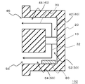
- FIG. 1 is a cross-sectional view showing the electro-acoustic transducer 100 according to the first embodiment.
- the electroacoustic transducer 100 includes an oscillation device 10, a waveguide 40, a waveguide 50, and an acoustic filter 80.
- the electroacoustic transducer 100 is used, for example, as a sound source of an electronic device (mobile phone, laptop computer, small game machine, etc.).
- the oscillation device 10 outputs the ultrasonic wave 30 from the first vibration surface.
- the oscillation device 10 outputs the ultrasonic wave 32 in the opposite phase to the ultrasonic wave 30 from the second vibration plane opposite to the first vibration plane.
- the waveguide 40 is provided on the first vibration plane and has an open end 46.
- the waveguide 50 is provided on the second vibration surface and has an opening end 56 oriented in the same direction as the opening end 46.
- the acoustic filter 80 is provided in the waveguide 50 and attenuates the ultrasonic waves 32.
- the electroacoustic transducer 100 further includes a housing 20.
- the housing 20 has the oscillation device 10 inside.
- the open end 46 and the open end 56 are provided on the surface of the housing 20.
- FIG. 2 is a cross-sectional view showing the oscillation device 10 shown in FIG.
- the oscillation device 10 includes a piezoelectric vibrator 11, a vibration member 12, and a support member 13.
- the vibrating member 12 restrains the piezoelectric vibrator 11.
- the support member 13 supports the vibrating member 12.
- the oscillation device 10 also includes a signal generation unit 92 and a control unit 94.
- the signal generation unit 92 is connected to the piezoelectric vibrator 11 and generates an electric signal to be input to the piezoelectric vibrator 11.
- the control unit 94 is connected to the signal generation unit 92, and controls the generation of the signal by the signal generation unit 92 based on the information input from the outside.
- the information input to the control unit 94 is an audio signal.
- the piezoelectric vibrator 11 By applying an electric field to the piezoelectric vibrator 11 based on a signal from the signal generation unit 92, the piezoelectric vibrator 11 performs an expansion and contraction movement.
- the vibrating member 12 vibrates in the vertical direction in FIG.
- the ultrasonic wave 32 has an ultrasonic wave 32 having a phase opposite to that of the ultrasonic wave 30 from a second vibration plane opposite to the first vibration plane from the first vibration plane. Is output.
- the oscillation device 10 is used as a parametric speaker. Therefore, the control unit 94 inputs a modulation signal as a parametric speaker via the signal generation unit 92.
- the piezoelectric vibrator 11 uses a sound wave of 20 kHz or more, for example, 100 kHz as a transport wave of a signal.
- a plurality of piezoelectric vibrators 11 and vibrating members 12 may be provided in an array. Thereby, the directivity of the ultrasonic wave 30 and the ultrasonic wave 32 which the oscillation apparatus 10 outputs can be improved.
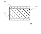
- FIG. 3 is a cross-sectional view showing the piezoelectric vibrator 11 shown in FIG.
- the piezoelectric vibrator 11 includes a piezoelectric body 14, an upper electrode 15, and a lower electrode 16. Also, the piezoelectric vibrator 11 has, for example, a circular shape, an elliptical shape or a rectangular shape.
- the piezoelectric body 14 is sandwiched between the upper electrode 15 and the lower electrode 16.
- the piezoelectric body 14 is made of a material having a piezoelectric effect, and is made of, for example, lead zirconate titanate (PZT) or barium titanate (BaTiO 3 ).
- the thickness of the piezoelectric body 14 is preferably 10 um to 1 mm.
- the thickness is less than 10 um, when the piezoelectric body 14 is formed of a brittle material, breakage or the like easily occurs. On the other hand, when the thickness exceeds 1 mm, the electric field strength of the piezoelectric body 14 is reduced. Therefore, the energy conversion efficiency is reduced.
- the upper electrode 15 and the lower electrode 16 are made of, for example, silver or silver / palladium alloy.
- the thickness of the upper electrode 15 and the lower electrode 16 is preferably 1 to 50 ⁇ m. If the thickness is less than 1 um, uniform molding becomes difficult. On the other hand, when it exceeds 50 um, the upper electrode 15 or the lower electrode 16 becomes a constraining surface with respect to the piezoelectric body 14 to cause a decrease in energy conversion efficiency.
- the vibrating member 12 is made of a material having a high modulus of elasticity with respect to the ceramic material, and is made of, for example, phosphor bronze or stainless steel.
- the thickness of the vibrating member 12 is preferably 5 to 500 um.
- the longitudinal elastic modulus of the vibrating member 12 is preferably 1 to 500 GPa. If the longitudinal elastic modulus of the vibrating member 12 is excessively low or high, the characteristics and reliability as a mechanical vibrator may be impaired.
- the waveguide 40 is composed of an inner region 42 constituting the oscillation device 10 side and an outer region 44 constituting the opening end 46 side.
- the waveguide 50 is constituted by an inner region 52 constituting the oscillation device 10 side and an outer region 54 constituting the opening end 56 side and being parallel to each other with the outer region 44.
- the waveguide 40 is bent at a right angle at the junction of the inner region 42 and the outer region 44.
- the waveguide 40 may have a curved shape in its entirety including the inner region 42 and the outer region 44.
- the waveguide 50 is bent at a right angle at the junction of the inner region 52 and the outer region 54.
- the waveguide 50 may be curved in the entire area of the inner region 52 and the outer region 54.
- the difference d between the length of the waveguide 40 and the length of the waveguide 50 is (N + 3/4) ⁇ ⁇ ⁇ d ⁇ (n + 5/4) ⁇ ⁇ (n is an integer) It is.
- the difference d between the length of the waveguide 40 and the length of the waveguide 50 can be adjusted, for example, by adjusting the position of the oscillation device 10. For example, adjustment can be performed by moving the oscillation device 10 to the inner region 42 side or the inner region 52 side. As shown in FIG. 1, when the lengths of the outer region 44 and the outer region 54 are equal, assuming that the length of the inner region 42 is d1 and the length of the inner region 52 is d2, then
- the acoustic filter 80 is provided to cover the open end 56. When the ultrasonic waves 32 pass through the sonic filter 80, the sound pressure of the ultrasonic waves 32 is attenuated.
- the thickness of the acoustic wave filter 80 can be appropriately changed in accordance with the space control of the reproduction area described later.
- the principle of operation of the parametric speaker is that ultrasonic waves with AM modulation, DSB modulation, SSB modulation, FM modulation are emitted into the air, and the audible sound appears due to non-linear characteristics when the ultrasonic waves propagate in the air Sound reproduction.
- the term "nonlinear” as used herein means transition from laminar flow to turbulent flow when the Reynolds number represented by the ratio of the inertial action of the flow to the viscous action increases. That is, since the sound wave is finely disturbed in the fluid, the sound wave is non-linearly propagating. In particular, when ultrasonic waves are emitted into the air, harmonics associated with the non-linearity are significantly generated.
- sound waves are in a dense / dense state in which molecular groups in the air are mixed in density. If it takes time for air molecules to recover more than compression, air that can not be recovered after compression will collide with continuously propagating air molecules, producing shock waves and producing audible sounds.
- the parametric speaker can form a sound field only around the user and is excellent in terms of privacy protection.
- FIG. 4 is a graph showing the principle of sound reproduction by the electroacoustic transducer 100 shown in FIG.
- the electroacoustic transducer 100 outputs an ultrasonic wave 30 from the first vibration plane of the oscillation device 10 toward the waveguide 40. For this reason, a sound field is formed in a region located in the direction in which the open end 46 of the waveguide 40 faces.
- the electroacoustic transducer 100 also outputs ultrasonic waves 32 from the second vibration plane of the oscillation device 10 toward the waveguide 50.
- a sound field is formed in a region located in the direction in which the open end 56 of the waveguide 50 is directed.
- the ultrasonic wave 30 and the ultrasonic wave 32 travel in the space while showing some spread while having high directivity. Therefore, the ultrasonic waves 30 and 32 that are output from the open end 46 and the open end 56 facing in the same direction and travel in parallel with each other interfere with each other.
- the ultrasonic wave 30 having the wavelength ⁇ and the ultrasonic wave 32 are constituted by the first vibration plane of the oscillation device 10 and a plane opposite to the first vibration plane. It is emitted from each of the two vibration planes. For this reason, the ultrasonic waves 30 and 32 have opposite phases. That is, the phases of the ultrasonic waves 30 and 32 are shifted by ⁇ / 2.
- the difference d between the length of the waveguide 40 and the length of the waveguide 50 is (N + 3/4) ⁇ ⁇ ⁇ d ⁇ (n + 5/4) ⁇ ⁇ (n is an integer) It is. Therefore, when the ultrasonic wave 30 and the ultrasonic wave 32 collide, the ultrasonic wave 30 and the ultrasonic wave 32 interfere with each other to annihilate or weaken each other.
- the ultrasonic wave attenuates rapidly at a fixed distance.
- the sound pressure of the ultrasonic wave may increase or decrease the distance until the ultrasonic wave attenuates. That is, the higher the sound pressure of the ultrasonic wave, the more rapidly it attenuates at a greater distance.
- the ultrasonic waves 32 since the ultrasonic waves 32 pass through the acoustic wave filter 80 provided in the waveguide 50, the sound pressure of the ultrasonic waves 32 is attenuated at the stage of being output to the outside of the electroacoustic transducer 100. Therefore, the ultrasonic waves 32 attenuate more rapidly at a position closer to the electroacoustic transducer 100 than the ultrasonic waves 30 as shown in FIG.
- the ultrasonic waves 30 and the ultrasonic waves 32 interfere with each other to annihilate or weaken each other. In this way, it is possible to control the sound pressure in the space from the electroacoustic transducer 100 to a certain distance. Also, only the ultrasonic waves 30 travel in the space behind the position where the ultrasonic waves 32 are attenuated. Therefore, in the space behind the position where the ultrasonic wave 32 attenuates, a sound with a good sound pressure is reproduced.
- the difference d between the length of the waveguide 40 and the length of the waveguide 50 can take other numerical ranges, for example, (N + 1/4) ⁇ ⁇ ⁇ d ⁇ (n + 3/4) ⁇ ⁇ (n is an integer) It can also be done.
- the ultrasonic waves 30 and 32 strengthen each other. Accordingly, the reproduction sound pressure is increased in the space from the electroacoustic transducer 100 to the position where the ultrasonic wave 32 is attenuated.
- the ultrasonic wave 30 and the ultrasonic wave 32 having opposite phases to each other are respectively output from the opening end 46 and the opening end 56 facing in the same direction.
- the acoustic wave filter 80 is provided in the waveguide 50. Therefore, it is possible to control the sound pressure in the space from the electroacoustic transducer 100 to a certain distance where the ultrasonic waves 32 are attenuated. Further, in the space behind the position where the ultrasonic wave 32 attenuates, a sound with a good sound pressure is reproduced. Therefore, in sound reproduction, spatial control of the reproduction area in the front-rear direction as viewed from the user is possible.
- FIG. 5 is a cross-sectional view showing the electro-acoustic transducer 102 according to the second embodiment, and corresponds to FIG. 1 according to the first embodiment.
- the electro-acoustic transducer 102 according to the present embodiment is the same as the electro-acoustic transducer 100 according to the first embodiment except that the acoustic wave filter 80 is provided on the inner wall of the waveguide of the waveguide 50. is there.
- the ultrasonic waves 32 are output from the opening end 56 while colliding with the inner wall of the inner region 52 and the inner wall of the outer region 54 although not shown. Therefore, even if the acoustic filter 80 is provided on the inner wall of the waveguide 50, the sound pressure of the ultrasonic wave 32 is attenuated.
Landscapes
- Health & Medical Sciences (AREA)
- Otolaryngology (AREA)
- Physics & Mathematics (AREA)
- Engineering & Computer Science (AREA)
- Acoustics & Sound (AREA)
- Signal Processing (AREA)
- Circuit For Audible Band Transducer (AREA)
- Transducers For Ultrasonic Waves (AREA)
Abstract
Description
前記第1の振動面に設けられ、第1の開口端を有する第1の導波路と、
前記第2の振動面に設けられ、前記第1の開口端と同一の方向を向いた第2の開口端を有する第2の導波路と、
前記第2の導波路に設けられた、前記第2の音波を減衰する音波フィルタと、
を備える電気音響変換器が提供される。
(n+3/4)×λ<d<(n+5/4)×λ (nは整数)
である。導波路40の長さと導波路50の長さとの差dは、例えば発振装置10の位置を調整することにより調整できる。例えば、発振装置10を、内側領域42側または内側領域52側へ移動させることにより調整ができる。図1に示すように、外側領域44と外側領域54の長さが等しい場合、内側領域42の長さをd1、内側領域52の長さをd2としたとき、|d1-d2|=dとなる。
(n+3/4)×λ<d<(n+5/4)×λ (nは整数)
である。このため、超音波30と超音波32が衝突した場合、超音波30と超音波32は干渉して互いに消滅し、または弱め合う。
d=nλ (nは整数)
であることがより好ましい。
(n+1/4)×λ<d<(n+3/4)×λ (nは整数)
とすることもできる。この場合、超音波30と超音波32は、互いに強め合う。よって、電気音響変換器100から超音波32が減衰する位置までの空間において、再生音圧が増大することとなる。
Claims (9)
- 第1の振動面から第1の音波を出力し、前記第1の振動面とは逆の第2の振動面から前記第1の音波とは逆位相の第2の音波を出力する発振装置と、
前記第1の振動面に設けられ、第1の開口端を有する第1の導波路と、
前記第2の振動面に設けられ、前記第1の開口端と同一の方向を向いた第2の開口端を有する第2の導波路と、
前記第2の導波路に設けられた、前記第2の音波を減衰する音波フィルタと、
を備える電気音響変換器。 - 請求項1に記載の電気音響変換器において、
前記第1の導波路の長さと前記第2の導波路の長さとの差dは、
(n+3/4)×λ<d<(n+5/4)×λ (nは整数)
である電気音響変換器。 - 請求項1または2に記載の電気音響変換器において、
前記第1の導波路の長さと前記第2の導波路の長さとの差dは、
d=nλ (nは整数)
である電気音響変換器。 - 請求項1ないし3いずれか1項に記載の電気音響変換器において、
前記第1の音波および前記第2の音波は、超音波である電気音響変換器。 - 請求項1ないし4いずれか1項に記載の電気音響変換器において、
前記発振装置と接続する信号生成部と、
前記信号生成部と接続し、前記信号生成部による信号の生成を制御する制御部と、
をさらに備える電気音響変換器。 - 請求項1ないし5いずれか1項に記載の電気音響変換器において、
前記音波フィルタは、前記第2の開口端を覆うように設けられている電気音響変換器。 - 請求項1ないし5いずれか1項に記載の電気音響変換器において、
前記音波フィルタは、前記第2の導波路の内壁に設けられている電気音響変換器。 - 請求項1ないし7いずれか1項に記載の電気音響変換器において、
前記第1の導波路は、前記発振装置側を構成する第1の内側領域と、前記第1の開口端側を構成する第1の外側領域により構成されており、
前記第2の導波路は、前記発振装置側を構成する第2の内側領域と、前記第2の開口端側を構成し、かつ前記第1の外側領域とは互いに平行である第2の外側領域により構成されている電気音響変換器。 - 請求項1ないし8いずれか1項に記載の電気音響変換器において、
前記発振装置を内部に有する筐体をさらに備え、
前記第1の開口端および前記第2の開口端は、前記筐体の表面に設けられている電気音響変換器。
Priority Applications (4)
| Application Number | Priority Date | Filing Date | Title |
|---|---|---|---|
| CN201180061401.2A CN103262568B (zh) | 2010-12-28 | 2011-12-20 | 电声换能器 |
| EP11852459.4A EP2661099B1 (en) | 2010-12-28 | 2011-12-20 | Electroacoustic transducer |
| JP2012550707A JP5910507B2 (ja) | 2010-12-28 | 2011-12-20 | 電気音響変換器 |
| US13/993,583 US9247338B2 (en) | 2010-12-28 | 2011-12-20 | Electroacoustic transducer |
Applications Claiming Priority (2)
| Application Number | Priority Date | Filing Date | Title |
|---|---|---|---|
| JP2010-291871 | 2010-12-28 | ||
| JP2010291871 | 2010-12-28 |
Publications (1)
| Publication Number | Publication Date |
|---|---|
| WO2012090433A1 true WO2012090433A1 (ja) | 2012-07-05 |
Family
ID=46382574
Family Applications (1)
| Application Number | Title | Priority Date | Filing Date |
|---|---|---|---|
| PCT/JP2011/007100 Ceased WO2012090433A1 (ja) | 2010-12-28 | 2011-12-20 | 電気音響変換器 |
Country Status (5)
| Country | Link |
|---|---|
| US (1) | US9247338B2 (ja) |
| EP (1) | EP2661099B1 (ja) |
| JP (1) | JP5910507B2 (ja) |
| CN (1) | CN103262568B (ja) |
| WO (1) | WO2012090433A1 (ja) |
Cited By (2)
| Publication number | Priority date | Publication date | Assignee | Title |
|---|---|---|---|---|
| JP2020088711A (ja) * | 2018-11-29 | 2020-06-04 | ヤマハ株式会社 | 電気音響変換器 |
| JP2020088710A (ja) * | 2018-11-29 | 2020-06-04 | ヤマハ株式会社 | 電気音響変換器 |
Families Citing this family (4)
| Publication number | Priority date | Publication date | Assignee | Title |
|---|---|---|---|---|
| US8861774B2 (en) * | 2010-09-27 | 2014-10-14 | Panasonic Patent Center | Sound reproduction device |
| US12087283B2 (en) * | 2020-11-12 | 2024-09-10 | Samsung Electronics Co., Ltd. | Electronic apparatus and controlling method thereof |
| CN112887874A (zh) * | 2021-01-14 | 2021-06-01 | 四川湖山电器股份有限公司 | 一种基于全频段声波控制的强声系统 |
| JP7726294B2 (ja) * | 2022-10-26 | 2025-08-20 | 株式会社村田製作所 | 超音波トランスデューサおよびこれを備えるパラメトリックスピーカ |
Citations (10)
| Publication number | Priority date | Publication date | Assignee | Title |
|---|---|---|---|---|
| JPS6468099A (en) * | 1987-09-08 | 1989-03-14 | Matsushita Electric Industrial Co Ltd | Speaker system |
| JPH01119200A (ja) * | 1987-09-25 | 1989-05-11 | Siemens Ag | 超音波変換器 |
| JPH0698384A (ja) * | 1991-08-15 | 1994-04-08 | Misawa Homes Co Ltd | スピーカー装置 |
| JPH11262084A (ja) * | 1998-01-09 | 1999-09-24 | Sony Corp | スピーカ装置及びオーディオ信号送信装置 |
| JP2000036993A (ja) | 1998-07-21 | 2000-02-02 | Nec Corp | 超指向性スピーカ装置 |
| JP2002345077A (ja) | 2001-02-07 | 2002-11-29 | Kansai Tlo Kk | 超音波スピーカによる立体音場形成システム |
| JP2008113194A (ja) | 2006-10-30 | 2008-05-15 | Mitsubishi Electric Engineering Co Ltd | 超音波素子および超指向性スピーカ |
| WO2008084806A1 (ja) | 2007-01-12 | 2008-07-17 | Nec Corporation | 圧電アクチュエータおよび電子機器 |
| JP2009046236A (ja) | 2007-08-17 | 2009-03-05 | Mitsubishi Electric Engineering Co Ltd | マンコンベア用のポスト |
| JP2010091871A (ja) | 2008-10-09 | 2010-04-22 | Seiko Epson Corp | 印刷装置 |
Family Cites Families (9)
| Publication number | Priority date | Publication date | Assignee | Title |
|---|---|---|---|---|
| US4875546A (en) * | 1988-06-02 | 1989-10-24 | Teledyne Industries, Inc. | Loudspeaker with acoustic band-pass filter |
| US5313525A (en) * | 1992-04-02 | 1994-05-17 | Yamaha Corporation | Acoustic apparatus with secondary quarterwave resonator |
| DE659030T1 (de) | 1993-12-16 | 1996-01-04 | Toshiba Kawasaki Kk | Lautsprechersystem für Fernsehgeräte. |
| FR2824990B1 (fr) | 2001-05-15 | 2003-09-26 | Jean Pierre Morkerken | Emetteur de son et haut-parleur |
| US7313242B2 (en) * | 2004-03-16 | 2007-12-25 | Palo Alto Research Center Incorporated | Hypersonic transducer |
| JP4103875B2 (ja) | 2004-09-16 | 2008-06-18 | セイコーエプソン株式会社 | 超音波トランスデューサ、超音波スピーカ、音響システム、及び超音波トランスデューサの制御方法 |
| US7688992B2 (en) | 2005-09-12 | 2010-03-30 | Richard Aylward | Seat electroacoustical transducing |
| JP4293378B2 (ja) * | 2007-04-04 | 2009-07-08 | 株式会社船井電機新応用技術研究所 | マイクロフォンユニット、及び、接話型の音声入力装置、並びに、情報処理システム |
| JP5325555B2 (ja) | 2008-12-05 | 2013-10-23 | 船井電機株式会社 | マイクロホンユニット |
-
2011
- 2011-12-20 US US13/993,583 patent/US9247338B2/en not_active Expired - Fee Related
- 2011-12-20 JP JP2012550707A patent/JP5910507B2/ja not_active Expired - Fee Related
- 2011-12-20 WO PCT/JP2011/007100 patent/WO2012090433A1/ja not_active Ceased
- 2011-12-20 CN CN201180061401.2A patent/CN103262568B/zh not_active Expired - Fee Related
- 2011-12-20 EP EP11852459.4A patent/EP2661099B1/en not_active Not-in-force
Patent Citations (10)
| Publication number | Priority date | Publication date | Assignee | Title |
|---|---|---|---|---|
| JPS6468099A (en) * | 1987-09-08 | 1989-03-14 | Matsushita Electric Industrial Co Ltd | Speaker system |
| JPH01119200A (ja) * | 1987-09-25 | 1989-05-11 | Siemens Ag | 超音波変換器 |
| JPH0698384A (ja) * | 1991-08-15 | 1994-04-08 | Misawa Homes Co Ltd | スピーカー装置 |
| JPH11262084A (ja) * | 1998-01-09 | 1999-09-24 | Sony Corp | スピーカ装置及びオーディオ信号送信装置 |
| JP2000036993A (ja) | 1998-07-21 | 2000-02-02 | Nec Corp | 超指向性スピーカ装置 |
| JP2002345077A (ja) | 2001-02-07 | 2002-11-29 | Kansai Tlo Kk | 超音波スピーカによる立体音場形成システム |
| JP2008113194A (ja) | 2006-10-30 | 2008-05-15 | Mitsubishi Electric Engineering Co Ltd | 超音波素子および超指向性スピーカ |
| WO2008084806A1 (ja) | 2007-01-12 | 2008-07-17 | Nec Corporation | 圧電アクチュエータおよび電子機器 |
| JP2009046236A (ja) | 2007-08-17 | 2009-03-05 | Mitsubishi Electric Engineering Co Ltd | マンコンベア用のポスト |
| JP2010091871A (ja) | 2008-10-09 | 2010-04-22 | Seiko Epson Corp | 印刷装置 |
Cited By (5)
| Publication number | Priority date | Publication date | Assignee | Title |
|---|---|---|---|---|
| JP2020088711A (ja) * | 2018-11-29 | 2020-06-04 | ヤマハ株式会社 | 電気音響変換器 |
| JP2020088710A (ja) * | 2018-11-29 | 2020-06-04 | ヤマハ株式会社 | 電気音響変換器 |
| US11595752B2 (en) | 2018-11-29 | 2023-02-28 | Yamaha Corporation | Electroacoustic transducer |
| JP7247549B2 (ja) | 2018-11-29 | 2023-03-29 | ヤマハ株式会社 | 電気音響変換器 |
| JP7338147B2 (ja) | 2018-11-29 | 2023-09-05 | ヤマハ株式会社 | 電気音響変換器 |
Also Published As
| Publication number | Publication date |
|---|---|
| CN103262568A (zh) | 2013-08-21 |
| EP2661099A1 (en) | 2013-11-06 |
| US9247338B2 (en) | 2016-01-26 |
| EP2661099A4 (en) | 2014-06-11 |
| CN103262568B (zh) | 2017-03-29 |
| US20130266151A1 (en) | 2013-10-10 |
| JP5910507B2 (ja) | 2016-04-27 |
| EP2661099B1 (en) | 2018-10-17 |
| JPWO2012090433A1 (ja) | 2014-06-05 |
Similar Documents
| Publication | Publication Date | Title |
|---|---|---|
| CN102959991B (zh) | 振荡器 | |
| JP5910507B2 (ja) | 電気音響変換器 | |
| CN102959992B (zh) | 振荡器和电子设备 | |
| JP2012015758A (ja) | 発振装置、その製造方法、電子機器 | |
| CN104335598A (zh) | 扬声器设备和电子设备 | |
| JP6021184B2 (ja) | 電子装置 | |
| WO2014061584A1 (ja) | 電気音響変換器、その製造方法、及びその電気音響変換器を用いた電子機器 | |
| JP5617412B2 (ja) | 発振装置および電子機器 | |
| JP2012015757A (ja) | 発振装置および電子機器 | |
| WO2013121489A1 (ja) | 電気音響変換器及び電子機器 | |
| JP5527082B2 (ja) | 電気音響変換器 | |
| JP5488266B2 (ja) | 発振装置 | |
| JP5471934B2 (ja) | 電子機器 | |
| JP2012142649A (ja) | 電気音響変換器 | |
| JP5696434B2 (ja) | 電子機器 | |
| JP2012029089A (ja) | 電気音響変換器 | |
| JP2012015764A (ja) | 発振装置 | |
| JP2012029111A (ja) | 発振装置 | |
| JP2012217034A (ja) | 発振装置および携帯端末装置 | |
| JP2012029090A (ja) | 電気音響変換器 | |
| JP2012015756A (ja) | 電子機器および発振ユニット | |
| JP2012029098A (ja) | 発振装置および電子機器 | |
| JP2012217030A (ja) | 電子機器、電子機器の出力制御方法、および発振装置 | |
| JP2018146927A (ja) | 残響支援装置 | |
| JP2012029082A (ja) | 電子機器 |
Legal Events
| Date | Code | Title | Description |
|---|---|---|---|
| 121 | Ep: the epo has been informed by wipo that ep was designated in this application |
Ref document number: 11852459 Country of ref document: EP Kind code of ref document: A1 |
|
| ENP | Entry into the national phase |
Ref document number: 2012550707 Country of ref document: JP Kind code of ref document: A |
|
| WWE | Wipo information: entry into national phase |
Ref document number: 13993583 Country of ref document: US Ref document number: 2011852459 Country of ref document: EP |
|
| NENP | Non-entry into the national phase |
Ref country code: DE |