WO2012090591A1 - 表示装置 - Google Patents
表示装置 Download PDFInfo
- Publication number
- WO2012090591A1 WO2012090591A1 PCT/JP2011/075772 JP2011075772W WO2012090591A1 WO 2012090591 A1 WO2012090591 A1 WO 2012090591A1 JP 2011075772 W JP2011075772 W JP 2011075772W WO 2012090591 A1 WO2012090591 A1 WO 2012090591A1
- Authority
- WO
- WIPO (PCT)
- Prior art keywords
- light
- unit
- display
- light guide
- refractive index
- Prior art date
- Legal status (The legal status is an assumption and is not a legal conclusion. Google has not performed a legal analysis and makes no representation as to the accuracy of the status listed.)
- Ceased
Links
Images




Classifications
-
- G—PHYSICS
- G09—EDUCATION; CRYPTOGRAPHY; DISPLAY; ADVERTISING; SEALS
- G09F—DISPLAYING; ADVERTISING; SIGNS; LABELS OR NAME-PLATES; SEALS
- G09F13/00—Illuminated signs; Luminous advertising
- G09F13/18—Edge-illuminated signs
-
- B—PERFORMING OPERATIONS; TRANSPORTING
- B60—VEHICLES IN GENERAL
- B60K—ARRANGEMENT OR MOUNTING OF PROPULSION UNITS OR OF TRANSMISSIONS IN VEHICLES; ARRANGEMENT OR MOUNTING OF PLURAL DIVERSE PRIME-MOVERS IN VEHICLES; AUXILIARY DRIVES FOR VEHICLES; INSTRUMENTATION OR DASHBOARDS FOR VEHICLES; ARRANGEMENTS IN CONNECTION WITH COOLING, AIR INTAKE, GAS EXHAUST OR FUEL SUPPLY OF PROPULSION UNITS IN VEHICLES
- B60K35/00—Instruments specially adapted for vehicles; Arrangement of instruments in or on vehicles
- B60K35/20—Output arrangements, i.e. from vehicle to user, associated with vehicle functions or specially adapted therefor
- B60K35/21—Output arrangements, i.e. from vehicle to user, associated with vehicle functions or specially adapted therefor using visual output, e.g. blinking lights or matrix displays
-
- B—PERFORMING OPERATIONS; TRANSPORTING
- B60—VEHICLES IN GENERAL
- B60K—ARRANGEMENT OR MOUNTING OF PROPULSION UNITS OR OF TRANSMISSIONS IN VEHICLES; ARRANGEMENT OR MOUNTING OF PLURAL DIVERSE PRIME-MOVERS IN VEHICLES; AUXILIARY DRIVES FOR VEHICLES; INSTRUMENTATION OR DASHBOARDS FOR VEHICLES; ARRANGEMENTS IN CONNECTION WITH COOLING, AIR INTAKE, GAS EXHAUST OR FUEL SUPPLY OF PROPULSION UNITS IN VEHICLES
- B60K35/00—Instruments specially adapted for vehicles; Arrangement of instruments in or on vehicles
- B60K35/50—Instruments characterised by their means of attachment to or integration in the vehicle
-
- B—PERFORMING OPERATIONS; TRANSPORTING
- B60—VEHICLES IN GENERAL
- B60K—ARRANGEMENT OR MOUNTING OF PROPULSION UNITS OR OF TRANSMISSIONS IN VEHICLES; ARRANGEMENT OR MOUNTING OF PLURAL DIVERSE PRIME-MOVERS IN VEHICLES; AUXILIARY DRIVES FOR VEHICLES; INSTRUMENTATION OR DASHBOARDS FOR VEHICLES; ARRANGEMENTS IN CONNECTION WITH COOLING, AIR INTAKE, GAS EXHAUST OR FUEL SUPPLY OF PROPULSION UNITS IN VEHICLES
- B60K2360/00—Indexing scheme associated with groups B60K35/00 or B60K37/00 relating to details of instruments or dashboards
- B60K2360/20—Optical features of instruments
- B60K2360/33—Illumination features
-
- B—PERFORMING OPERATIONS; TRANSPORTING
- B60—VEHICLES IN GENERAL
- B60K—ARRANGEMENT OR MOUNTING OF PROPULSION UNITS OR OF TRANSMISSIONS IN VEHICLES; ARRANGEMENT OR MOUNTING OF PLURAL DIVERSE PRIME-MOVERS IN VEHICLES; AUXILIARY DRIVES FOR VEHICLES; INSTRUMENTATION OR DASHBOARDS FOR VEHICLES; ARRANGEMENTS IN CONNECTION WITH COOLING, AIR INTAKE, GAS EXHAUST OR FUEL SUPPLY OF PROPULSION UNITS IN VEHICLES
- B60K2360/00—Indexing scheme associated with groups B60K35/00 or B60K37/00 relating to details of instruments or dashboards
- B60K2360/20—Optical features of instruments
- B60K2360/33—Illumination features
- B60K2360/34—Backlit symbols
-
- G—PHYSICS
- G09—EDUCATION; CRYPTOGRAPHY; DISPLAY; ADVERTISING; SEALS
- G09F—DISPLAYING; ADVERTISING; SIGNS; LABELS OR NAME-PLATES; SEALS
- G09F13/00—Illuminated signs; Luminous advertising
- G09F13/18—Edge-illuminated signs
- G09F2013/184—Information to display
- G09F2013/1854—Light diffusing layer
-
- G—PHYSICS
- G09—EDUCATION; CRYPTOGRAPHY; DISPLAY; ADVERTISING; SEALS
- G09F—DISPLAYING; ADVERTISING; SIGNS; LABELS OR NAME-PLATES; SEALS
- G09F13/00—Illuminated signs; Luminous advertising
- G09F13/18—Edge-illuminated signs
- G09F2013/184—Information to display
- G09F2013/1863—Layer with different refractive index
-
- G—PHYSICS
- G09—EDUCATION; CRYPTOGRAPHY; DISPLAY; ADVERTISING; SEALS
- G09F—DISPLAYING; ADVERTISING; SIGNS; LABELS OR NAME-PLATES; SEALS
- G09F13/00—Illuminated signs; Luminous advertising
- G09F13/20—Illuminated signs; Luminous advertising with luminescent surfaces or parts
- G09F13/22—Illuminated signs; Luminous advertising with luminescent surfaces or parts electroluminescent
- G09F2013/222—Illuminated signs; Luminous advertising with luminescent surfaces or parts electroluminescent with LEDs
Definitions
- the present invention relates to a display device mounted on an automobile or the like that guides light emitted from a light source by a light guide unit to illuminate a design display unit or the like.
- Patent Documents 1 to 3 As this kind of technology, for example, in Patent Documents 1 to 3, a sheet-like sheet-like member having flexibility and translucency, and light more than a sheet-like member arranged on both surfaces of the sheet-like member. A light guide including a low refractive index portion having a low refractive index is disclosed.
- the light guides disclosed in Patent Documents 1 to 3 do not consider a design in which the light emitted from the light guide is guided, and therefore a predetermined design using the light guide is not considered.
- the applicant of the present application guides light incident from the end of the light guide member, and provides a light diffusing part in accordance with the design display part, so that light is emitted from an extra part in the light guide part.
- a display device that can prevent or reduce and efficiently illuminate the indicator portion displayed by the design display portion (Japanese Patent Application No. 2010-110608).
- the display device has a problem that the closer to the light source, the higher the emission luminance of the indicator portion, and the light is attenuated and the emission luminance is lowered as the distance from the light source to the indicator portion increases.
- a large amount of light is emitted (consumed) in order from the indicator part closest to the light source.
- the indicator part located at there is a problem that the light emission luminance is lowered.
- the indicator portion located behind the hole opened for the purpose of inserting the pointer shaft or the like as viewed from the light source causes a shadow of the hole and the luminance decreases.
- the light reflected from the end face brightens the vicinity of the end face and causes uneven brightness.
- the present invention provides a display device capable of illuminating all index portions with substantially uniform brightness regardless of the distance from the light source to the index portion and the positional relationship of the index portions. It is intended.
- the present invention provides a light source, a light guide unit that guides light emitted from the light source, and a design display unit that includes a light emission unit that emits the light.
- the low-refractive-index part which is provided between the light guide part and the design display part and has a light refractive index lower than that of the light guide part, and is formed in the light guide part and guides the light guide part.
- a display light adjusting unit for changing the emission efficiency is provided at least in a region corresponding to the light emitting unit.
- the display light adjusting unit is constituted by the light diffusing unit and a light adjusting low refractive index unit.
- an indicator portion (light emitting portion) that transmits light in accordance with the design of the design display portion, and providing an opaque portion that does not transmit light other than that, an extra portion of the light guide portion is provided. It is possible to prevent or reduce the emission of light and efficiently illuminate the design displayed by the design display unit. In addition, it is possible to provide a display device that can illuminate all index parts with substantially uniform luminance regardless of the distance from the light source to the index part and the positional relationship of the index parts.
- FIG. 2 (second embodiment diagram) Schematic diagram of the light path in the light guide Sectional drawing of the display apparatus of 3rd embodiment Sectional drawing of the display apparatus of 4th embodiment Sectional drawing of the display apparatus of 5th embodiment Sectional drawing of the display apparatus of 6th embodiment
- the display device 100 includes a display member 10 that displays a predetermined design and a light source 20 that emits light.
- the display device 100 receives light emitted from the light source 20 at the end of the display member 10 and emits it from a predetermined region of the display member 10.
- the display device 100 is used for, for example, a vehicle instrument, a mobile phone, a display display, and the like.
- the display device 100 is a vehicle instrument.
- the light source 20 is a rod-shaped light source that emits light in a straight line, and is composed of, for example, a light-emitting element such as a cold cathode tube, a light-emitting diode, or an organic EL element.
- the light source 20 is provided at a position where incident light enters the display member 10 (light guide unit 11 described later). Specifically, for example, the light source 20 is provided so that the light emitting portion of the light source 20 faces the side surface of the display member 10 (light guide portion 11 described later), and the light emitted from the light source 20 is guided. Incident into the light unit 11.
- the display member 10 includes a light guide portion 11, a design display portion 12, a surface light diffusion portion 13 a, a back light diffusion portion 13 b, a low refractive index portion 14 a, and a light adjustment low refractive index.
- the display light adjusting unit 15 is a surface light adjusting unit 15a including a surface light diffusing unit 13a and a light adjusting low refractive index unit 14b, or a back light adjusting unit including a back light diffusing unit 13b and a light adjusting low refractive index unit 14b. Part 15b.
- the light guide unit 11 takes in the light emitted from the light source 20 and guides it.
- the light guide unit 11 is formed of a plate-shaped synthetic resin member (for example, a polycarbonate plate or the like) having transparent or translucent translucency (including translucency).
- the design display unit 12 is disposed on the surface 111 side of the light guide unit 11 and does not emit (does not transmit) light, and an indicator unit (light emitting unit) that emits light and displays a design or the like brightly. 122.
- the opaque portion 121 is formed by printing, painting, etc., using light-shielding ink, etc., and forms a design by cutting out the design of a vehicle instrument (design representing characters, pictures, figures, symbols, etc.) To do.
- the non-transmissive portion 121 may be a layer having translucency (including semi-translucency).
- the indicator part 122 is a part of the design of the vehicle instrument cut out in the non-permeable part 121 as a through hole (can be changed to a notch as appropriate).
- the indicator part 122 is formed by drawing printing or the like.
- the indicator part 122 should just be what can permeate
- the indicator portion 122 that transmits light is provided in accordance with the design of the design display portion 12, and the light transmitting portion 121 that does not transmit light otherwise is used as the light from an extra portion of the light guide portion 11. Can be prevented or reduced, and the design displayed by the design display unit 12 can be efficiently illuminated.
- the light diffusing unit 13 (the front surface light diffusing unit 13a and the back surface light diffusing unit 13b) is provided on the front surface 111 or the back surface 112 of the light guiding unit 11 by printing, painting or the like using a material having light diffusibility. 11 diffuses the light guided. The diffused light passes through the indicator portion 122 and exits from the indicator portion 122.
- the light diffusing unit 13 is provided in a region corresponding to the indicator unit 122. For example, the light diffusing unit 13 is provided so that at least a part thereof overlaps the indicator unit 122 when viewed from the normal direction of the surface of the design display unit 12.
- the light diffusing unit 13 may be larger than the index unit 122, for example, may have a wider shape than the index unit 122, or may have a similar shape larger than the index unit 122. good. Thereby, even if the light diffusing unit 13 is provided at a position shifted from the index unit 122 (that is, a position deviated from the region corresponding to the index unit 122), the light can be diffused toward the index unit 122.
- the indicator unit 122 can efficiently emit the light diffused by the light diffusing unit 13. In addition, the viewing angle of the index unit 122 is widened.
- the light diffusion part 13 should just be the structure which has light diffusivity, for example, the light diffusion part 13 is a dot pattern etc. which consists of an uneven
- the light diffusing unit 13 may be provided with light diffusing bubbles on the surface of the light guiding unit 11 having translucency.
- the light diffusion part 13 may be provided with the same material as the light guide part 11.
- the light guide part 11 and the light diffusion part 13 may be configured by mixing light-diffusing gold powder or the like in a light-transmitting glass.
- the light diffusing unit 13 is a film (sheet) -like member having light diffusibility, and this is provided on the back surface 112 of the light guide unit 11.
- the light diffusing unit 13 is provided at substantially the same position and the same shape as the indicator unit 122. With such a configuration, the light diffusing unit 13 can be provided without requiring a complicated design. Note that the term “diffusion” as used herein appropriately includes changing the course of light by irregular reflection, scattering, refraction, reflection, or the like.
- the surface light diffusing unit 13a is a transmissive light diffusing unit disposed on the surface 111 of the light guide unit 11, and mainly scatters and refracts light incident from the surface 111 of the light guide unit 11 toward the indicator unit 122 side. Etc. to diffuse light.
- the back surface light diffusing unit 13b is disposed on the back surface 112 of the light guide unit 11 and is an impermeable light diffusing unit. Light incident from the back surface 112 of the light guide unit 11 is directed to the light guide unit 11 side. Diffuse light by reflection, diffuse reflection, scattering, etc. A part of the back surface 112 of the light guide portion 11 excluding the back surface light diffusion portion 13b is an exposed surface 113 that touches the air layer.
- the low refractive index portion 14 a is provided so as to cover the entire surface 111 of the light guide portion 11.
- the light adjusting low refractive index portion 14b is disposed between the light guide portion 11 and the light diffusion portion 13 (the front surface light diffusion portion 13a and the back surface light diffusion portion 13b).
- the low refractive index portion 14a and the light adjusting low refractive index portion 14b are transparent or translucent (including semi-transparent) and have a lower refractive index of light than the light guide unit 11.
- the low refractive index portion 14a and the light adjusting low refractive index portion 14b are formed by printing, painting, or the like using, for example, a synthetic resin having a light refractive index lower than that of the light guide portion 11.
- the low refractive index portion 14a and the light adjusting low refractive index portion 14b may be provided by a flat plate-shaped synthetic resin member (for example, an acrylic plate) having translucency.
- the display light adjusting unit 15 includes a surface light adjusting unit 15a (see FIG. 4) including a surface light diffusing unit 13a and a light adjusting low refractive index unit 14b, a back light diffusing unit 13b, and a light adjusting low refractive index unit 14b. And a back light adjusting unit 15b (see FIG. 3).
- the display light adjusting unit 15 is formed by disposing the light adjusting low refractive index portion 14b in a dot pattern (by printing).
- the display light adjusting unit 15 may be provided by providing a dot-patterned light diffusing unit 13 (front surface light diffusing unit 13 a or back surface light diffusing unit 13 b).
- the display device is configured by the above configuration. In the following description, a method for adjusting the light emission rate in the display light adjusting unit 15 will be described.
- the light emitted from the light source 20 enters the light guide 11, repeats reflection at the interface of the light guide 11, and travels in the light guide 11.
- the first light beam 20 a totally reflected by the light adjusting low refractive index unit 14 b and the second light beam 20 b diffused by the light diffusion unit 13. And divided.
- the first light ray 20a is further totally reflected by the light adjusting low refractive index portion 14b and further travels in the light guide portion 11.
- the second light beam 20b diffused by the light diffusing unit 13 is emitted from the index unit 122 of the design display unit 12, and the index unit 122 is displayed brightly.
- the amount of light emitted from the indicator unit 122 is the area of the light diffusing unit 13 (surface light diffusing unit 13a, back surface light diffusing unit 13b) and the light adjusting low refractive index unit 14b per unit area of the display light adjusting unit 15. Adjusted by ratio. For example, when the area of the low refractive index portion for light adjustment 14b is large and the area of the light diffusion portion 13 is small, most of the light is totally reflected by the low refractive index portion for light adjustment 14b, and thus exits from the indicator portion 122. The amount of emitted light to be reduced is reduced (the emission efficiency is reduced).
- the display light adjusting unit 15 can appropriately reduce or increase the emitted light.
- the display light adjusting unit 15 As the distance of the display light adjusting unit 15 from the light source 20 increases, the ratio of the area of the light adjusting low refractive index portion 14b per unit area of the display light adjusting unit 15 is decreased. As a result, the display light adjusting unit 15 has a small amount of light adjusting low refractive index portion 14b when the distance from the light source 20 is short, so that the amount of light emitted from the indicator unit 122 is reduced (the emission efficiency is lowered). . Further, if the distance from the light source 20 is long, the light adjusting low refractive index portion 14b is small, and thus the amount of light emitted from the indicator portion 122 is large (the emission efficiency is high).
- the light guided in the light guide portion 11 travels in the light propagation direction by total reflection, but the light is scattered and attenuated by this process, and is guided as the distance from the light source 20 increases.
- the amount of light emitted decreases.
- light with substantially uniform luminance is emitted from the index unit 112 at a short distance from the light source 20 and the index unit 112 at a distance from the light source 20.
- the indicator unit 122 it is possible to darken the display brightness on the side close to the light source 20, and brighten the display brightness on the far side.
- the luminance unevenness of the display luminance is brightened not only in the luminance unevenness according to the distance from the light source 20 but also in the index portion end surface region 123 in the vicinity of the end surface of the light guide unit 11 as shown in FIG. If there is a light guide portion through hole 114 provided in the light guide portion 12 for reasons such as inserting a component into the light guide portion 11, the rear of the light guide portion through hole 114 or other indicator portion as viewed from the light source It tends to be dark in the indicator shade area 124 behind the screen.
- the emission efficiency is set low by the display light adjusting unit 15 in the indicator end face region 123, and the emission efficiency is set high by the display light adjusting unit 15 in the indicator shaded region 124, so that the luminance unevenness is reduced. Can be suppressed.
- the light emitted from the light source 20 is incident on the side surface of the light guide unit 11 of the display member 10.
- the light incident on the light guide unit 11 repeats total reflection at the interface between the light guide unit 11 and the low refractive index unit 14 a or the light guide unit 11 and the air layer, and travels inside the light guide unit 11. Part of the light traveling inside the light guide unit 11 reaches the display light adjustment unit 15.
- the display light adjusting unit 15 can appropriately reduce or increase the emitted light by changing the ratio of the area of the light diffusing unit 13 and the light adjusting low refractive index unit 14b per unit area. It is possible to illuminate the indicator portion 122 with substantially uniform luminance regardless of the distance between the indicator portions, the indicator portions, the positional relationship between the indicator portion and the hole, or the vicinity of the end face.
- both the front light adjustment unit 15a and the back light adjustment unit 15b may be provided.
- the low refractive index part 14a is provided over the whole surface 111 of the light guide part 11, as shown in FIG. 9, it diffuses from the light-diffusion part 13 to the low refractive index part 14a.
- the through-hole 141 may be formed at a position where the transmitted light passes.
- the impermeable part 121 formed in the design display part 12 is a layer which has non-light-transmitting property (light-shielding property), it is a layer which has translucency (a semi-transparent property is included). It may be. Furthermore, the non-transmissive portion 121 formed using a light-transmitting layer may be provided so as to cover the indicator portion 122 as shown in FIG. (Fifth embodiment)
- the display member 10 demonstrated the flat thing, as shown in FIG. 11, you may provide in a three-dimensional shape.
- the display member 10 can be processed into a three-dimensional shape by pressure forming or drawing.
- the present invention relates to a display device for a vehicle, for example, as a display device for displaying vehicle information, which displays an index such as a vehicle speed or an engine speed, and is capable of grasping a vehicle operation state by an indicator indicating the index. Applicable.
- Display member 11 Light guide part 12 Design display part 13 Light diffusion part 13a Surface light diffusion part 13b Back surface light diffusion part 14a Low refractive index part 14b Low refractive index part for light adjustment 15 Display light adjustment part 15a Front light adjustment part 15b Back surface light adjustment Portion 20
- Impervious portion 122 Indicator portion 123 Indicator portion end surface region 124 Indicator portion shadow Area 141 Through hole
Landscapes
- Engineering & Computer Science (AREA)
- Chemical & Material Sciences (AREA)
- Combustion & Propulsion (AREA)
- Transportation (AREA)
- Mechanical Engineering (AREA)
- Physics & Mathematics (AREA)
- General Physics & Mathematics (AREA)
- Theoretical Computer Science (AREA)
- Illuminated Signs And Luminous Advertising (AREA)
- Instrument Panels (AREA)
- Details Of Measuring Devices (AREA)
- Arrangements Of Lighting Devices For Vehicle Interiors, Mounting And Supporting Thereof, Circuits Therefore (AREA)
Abstract
光源から指標部までの距離や指標部の位置関係によらず、すべての指標部を略均一な輝度で照明することが可能な表示装置を提供する。 導光部11は光源20から出射された光を導光し、意匠表示部12は光が出射する光出射部122を有し、導光部12よりも光の屈折率が低い低屈折率部14aは導光部11と意匠表示部12との間に設けられ、光拡散部13は導光部11に形成され、導光部11が導光する光を拡散する。出射効率を変化させる表示光調整部15を、少なくとも光出射部122に対応する領域内に配設する。
Description
本発明は、光源から出射された光を導光部にて導光して意匠表示部等を照光する、自動車などに搭載される表示装置に関するものである。
この種の技術として、例えば、特許文献1乃至3には、可撓性及び透光性を有するシート状のシート状部材と、そのシート状部材の両面に配置された、シート状部材よりも光の屈折率が低い低屈折率部とを備えた導光体が開示されている。しかし、上記特許文献1乃至3に開示されている導光体では、導光体が導光して出射する光が照光する意匠を考慮していないため、この導光体を用いて所定の意匠を照光する場合に、効率良く意匠を照光することができない、という問題があった。
そこで、本願出願人は、導光部材の端部から入射した光を導光し、意匠表示部に合わせて光拡散部を設けることで、導光部における余計な部分から光が出射することを防止又は低減し、意匠表示部が表示する指標部を効率良く照光する表示装置を提案した(特願2010-110608号)。
しかしながら、前記表示装置は、光源に近い程、指標部の発光輝度が高く、光源から指標部までの距離が遠ざかるにしたがって光が減衰し、発光輝度が低くなる問題があった。また、複数の指標部が光源からみて略一直線上に並んでいるような場合、光源に近い指標部から順に多くの光が出射(消費)されるため、光源から見て、ある指標部の背後に位置する指標部においては、発光輝度が低くなるという問題があった。また、光源からみて指針軸等を挿通する等の目的で開けられた穴の背後に位置する指標部においては、穴の影ができて輝度が低下するという問題があった。また、端面形状によっては、端面で反射された光によって、端面近傍が明るくなり、輝度ムラが生じる問題があった。
本発明は、前述の課題を鑑みて、光源から指標部までの距離や指標部の位置関係によらず、すべての指標部を略均一な輝度で照明することが可能な表示装置を提供することを目的とするものである。
本発明は、前述の課題を解決するため、請求項1では、光源と、前記光源から出射された光を導光する導光部と、前記光が出射する光出射部を有する意匠表示部と、前記導光部と前記意匠表示部との間に設けられ、前記導光部よりも光の屈折率が低い低屈折率部と、前記導光部に形成され前記導光部が導光する前記光を拡散する光拡散部と、を備えた表示装置において、
少なくとも前記光出射部に対応する領域内に、出射効率を変化させる表示光調整部を備えるものである。
少なくとも前記光出射部に対応する領域内に、出射効率を変化させる表示光調整部を備えるものである。
また、請求項2では、前記表示光調整部は、前記光拡散部と光調整用低屈折率部とによって構成されているものである。
本発明では、意匠表示部の意匠に合わせて光を透過する指標部(光出射部)を設け、それ以外には光が透過しない不透過部を設けることで、導光部の余計な部分から光が出射することを防止又は低減し、意匠表示部が表示する意匠を効率良く照光できる。
また光源から指標部までの距離や指標部の位置関係によらず、略均一な輝度ですべての指標部を照明することが可能とする表示装置を提供できる。
また光源から指標部までの距離や指標部の位置関係によらず、略均一な輝度ですべての指標部を照明することが可能とする表示装置を提供できる。
以下、添付図面に基づいて、本発明の一実施形態を説明する。
表示装置100は、所定の意匠を表示する表示部材10と、光を出射する光源20とから構成される。
表示装置100は、光源20が出射した光を、表示部材10の端部で受光し、表示部材10の所定の領域から出射するものである。具体的に、表示装置100は、例えば、車両用計器、携帯電話、表示ディスプレイ等に用いられる。本実施形態では、表示装置100が、車両用計器のものである。
表示装置100は、光源20が出射した光を、表示部材10の端部で受光し、表示部材10の所定の領域から出射するものである。具体的に、表示装置100は、例えば、車両用計器、携帯電話、表示ディスプレイ等に用いられる。本実施形態では、表示装置100が、車両用計器のものである。
光源20は、光を直線状に出射する棒状の光源であり、例えば、冷陰極管、発光ダイオード、有機EL素子などの発光素子によって構成される。光源20は、出射する光を表示部材10(後述の導光部11)の内部に入射させる位置に設けられる。具体的に、例えば、光源20における光の出射部が、表示部材10(後述の導光部11)の側面に対向するように、光源20は設けられ、光源20から出射された光は、導光部11内部に入射する。
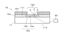
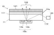
表示部材10は、図1に示すように、導光部11と、意匠表示部12と、表面光拡散部13aと、裏面光拡散部13bと、低屈折率部14aと、光調整用低屈折率部14bと、を備える。
表示光調整部15は、表面光拡散部13aと光調整用低屈折率部14bとからなる表面光調整部15a、又は、裏面光拡散部13bと光調整用低屈折率部14bとからなる裏面光調整部15bである。
表示光調整部15は、表面光拡散部13aと光調整用低屈折率部14bとからなる表面光調整部15a、又は、裏面光拡散部13bと光調整用低屈折率部14bとからなる裏面光調整部15bである。
導光部11は、光源20が出射した光を内部に取り込み導光する。導光部11は、ここでは、透明又は半透明の透光性(半透光性を含む)を有する平板状の合成樹脂製の部材(例えばポリカーボネート板等)で形成されている。
意匠表示部12は、導光部11の表面111側に配設され、光を出射しない(透過しない)不透過部121と、光を出射し意匠等を明るく表示する指標部(光出射部)122により構成される。
不透過部121は、遮光性のインク等を用いて、印刷、塗装等によって形成され、車両用計器の意匠(文字、絵、図形、記号等を表現する意匠)の部分を切り抜いた意匠を形成する。不透過部121は、透光性(半透光性を含む)を有する層であっても良い。
指標部122は、不透過部121において切り抜かれた車両用計器の意匠の部分を貫通孔(適宜、切り欠きに変更できる)にしたものである。ここでは、指標部122は、抜き絵印刷等によって形成される。また、指標部122は、後述の光拡散部13で拡散された光を透過するものであれば良いので、例えば、透光性を有する白色印刷等によって形成されても良い。
このように、意匠表示部12の意匠に合わせて、光が透過する指標部122を設け、それ以外は光が透過しない不透過部121とすることで、導光部11の余計な部分から光が出射することを防止又は低減し、意匠表示部12が表示する意匠を効率良く照光できる。
このように、意匠表示部12の意匠に合わせて、光が透過する指標部122を設け、それ以外は光が透過しない不透過部121とすることで、導光部11の余計な部分から光が出射することを防止又は低減し、意匠表示部12が表示する意匠を効率良く照光できる。
光拡散部13(表面光拡散部13aと裏面光拡散部13b)は、光拡散性を有する材料を用いて、印刷、塗装等によって導光部11の表面111又は裏面112に設けられ、導光部11が導光した光を拡散する。拡散された光は、指標部122を透過し、指標部122から出射する。光拡散部13は、指標部122に対応する領域に設けられる。例えば、光拡散部13は、その少なくとも一部が、意匠表示部12の表面の法線方向から見て、指標部122と重なるように設けられる。
また、光拡散部13は、指標部122よりも大きいものであっても良く、例えば、指標部122よりも幅広い形状であっても良く、また、指標部122よりも大きい相似形であっても良い。これにより、指標部122とずれた位置(つまり、指標部122と対応する領域から外れた位置)に、光拡散部13が設けられても、指標部122に向けて光を拡散することができ、指標部122は、光拡散部13で拡散された光を効率的に出射することができる。また、指標部122の視野角が広くなる。
また、光拡散部13は、光拡散性を有する構成であれば良いので、例えば、光拡散部13は、導光部11の面に直接、凹凸部等からなるドットパターン等を、マイクロドット、インプリント、エッチング等で成型したものであってもよい。光拡散部13は、透光性を有する導光部11の面に、光拡散性を有する気泡を設けたものであってもよい。この場合、光拡散部13は、導光部11と同じ材料で設けられてもよい。その他、透光性を有するガラス内に、光拡散性を有する金粉等を混入して、導光部11と光拡散部13とを構成しても良い。
光拡散部13は、本実施形態では、光拡散性を有するフィルム(シート)状の部材であり、これが導光部11の裏面112に設けられる。また、光拡散部13は、指標部122と略同じ位置、及び、略同じ形状によって設けられる。このような構成によって、複雑な設計を必要とせずに光拡散部13を設けることができる。なお、ここでいう拡散とは、乱反射、散乱、屈折、反射等によって、光の進路が変更されることを適宜含む。
表面光拡散部13aは、導光部11の表面111に配設され、透過性の光拡散部であり、導光部11の表面111から入射した光を指標部122側に、主に散乱、屈折等によって、光を拡散する。
また、裏面光拡散部13bは、導光部11の裏面112に配設され、不透過性の光拡散部であり、導光部11の裏面112から入射した光を導光部11側に、反射、乱反射、散乱等によって、光を拡散する。裏面光拡散部13bを除く導光部11の裏面112の一部は、空気層に触れる露出面113となっている。
また、裏面光拡散部13bは、導光部11の裏面112に配設され、不透過性の光拡散部であり、導光部11の裏面112から入射した光を導光部11側に、反射、乱反射、散乱等によって、光を拡散する。裏面光拡散部13bを除く導光部11の裏面112の一部は、空気層に触れる露出面113となっている。
低屈折率部14aは、導光部11の表面111全体を覆うように設けられる。
光調整用低屈折率部14bは、導光部11と、光拡散部13(表面光拡散部13a、裏面光拡散部13b)との間に配設される。
光調整用低屈折率部14bは、導光部11と、光拡散部13(表面光拡散部13a、裏面光拡散部13b)との間に配設される。
低屈折率部14a、光調整用低屈折率部14bは、透明又は半透明の透光性(半透光性を含む)を有し、導光部11よりも光の屈折率が低い。低屈折率部14a、光調整用低屈折率部14bは、例えば、導光部11よりも光の屈折率が低い合成樹脂を用いて、印刷、塗装等によって形成される。低屈折率部14a、光調整用低屈折率部14bは、透光性を有する平板状の合成樹脂製の部材(例えばアクリル板等)によって設けられても良い。
表示光調整部15は、表面光拡散部13aと光調整用低屈折率部14bとからなる表面光調整部15a(図4参照)と、裏面光拡散部13bと光調整用低屈折率部14bとからなる裏面光調整部15b(図3参照)とがある。
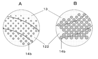
表示光調整部15は、図5に示すように、光調整用低屈折率部14bを(印刷によって)ドットパターン状に配設することで、形成される。
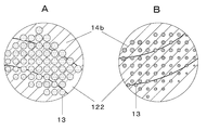
また、第二実施形態として、図6に示すように、ドットパターン状の光拡散部13(表面光拡散部13a又は裏面光拡散部13b)を設けることによって、表示光調整部15としてもよい。
また、第二実施形態として、図6に示すように、ドットパターン状の光拡散部13(表面光拡散部13a又は裏面光拡散部13b)を設けることによって、表示光調整部15としてもよい。
以上の構成により表示装置が構成される。以下の説明では、表示光調整部15における、光の出射率調整方法について述べる。
光源20から出射された光は、導光部11の内部に入り、導光部11の界面で反射を繰り返し、導光部11内を進行する。この導光された光は、表示光調整部15に到達すると、光調整用低屈折率部14bによって全反射される第一の光線20aと、光拡散部13によって拡散される第二の光線20bとに分かれる。第一の光線20aは、光調整用低屈折率部14bによって全反射されることでさらに導光部11内を進行する。光拡散部13により拡散された第二の光線20bは、意匠表示部12の指標部122から出射され、指標部122を明るく表示する。
指標部122から出射される光の量は、表示光調整部15の単位面積あたりの光拡散部13(表面光拡散部13a、裏面光拡散部13b)と光調整用低屈折率部14bの面積の比率により調整される。例えば、光調整用低屈折率部14bの面積が多く、光拡散部13の面積が少ない場合は、光の多くは光調整用低屈折率部14bにより全反射される為、指標部122から出射する出射光は少なくなる(出射効率が低くなる)。逆に、光調整用低屈折率部14bの面積が少なく、光拡散部13の面積が多い場合は、光拡散部13に拡散され、指標部122から出射する出射光は多くなる(出射効率が高くなる)。よって、表示光調整部15により、出射光を適宜減少・増大させることが可能となる。
光源20から表示光調整部15の距離が離れるにつれて、表示光調整部15の単位面積あたりの光調整用低屈折率部14bの面積の占める比率を減少させていく。これにより、表示光調整部15は、光源20からの距離が近いと光調整用低屈折率部14bが多いので、指標部122から出射される光の量は少なくなる(出射効率が低くなる)。また、光源20からの距離が遠いと光調整用低屈折率部14bが少ないので、指標部122から出射される光の量は多くなる(出射効率が高くなる)。
ところで、通常、導光部11の中の導光される光は、全反射により光の伝搬方向に進行していくが、その過程により光は散乱・減衰され、光源20より離れていくに従い導光される光量は減少していく。それに合わせ、表示光調整部15の出射効率を増加させていくことにより、光源20から近い距離にある指標部112と光源20から遠い距離にある指標部112を略均一の輝度の光が出射するように調整することが出来る。同様に、指標部122において、光源20に近い側の表示輝度を暗く、遠い側の表示輝度を明るくすることも可能である。
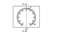
また、表示輝度の輝度ムラは、上記の光源20からの距離に応じた輝度ムラだけではなく、図7に示すように、導光部11の端面の近傍である指標部端面領域123では明るくなりやすく、導光部11に部品を挿入する等の理由により導光部12に設けられた導光部貫通穴114等がある場合、光源からみて導光部貫通穴114の背後もしくは他の指標部の背後になる指標部陰領域124では暗くなりやすい。これらに応じて、指標部端面領域123では表示光調整部15によって出射効率を低く設定し、指標部陰領域124では表示光調整部15によって出射効率を高く設定することで、これらの輝度ムラを抑えることができる。
このように構成された表示装置100においては、光源20から出射された光は、表示部材10の導光部11の側面に入射する。導光部11に入射した光は、導光部11と低屈折率部14a、又は導光部11と空気層との界面で全反射を繰り返し、導光部11の内部を進む。導光部11の内部を進む光の一部は、表示光調整部15に到達する。表示光調整部15は、単位面積あたりの光拡散部13と光調整用低屈折率部14bの面積の比率を変化させることにより、出射光を適宜減少・増大させることが可能となり、光源20からの距離や指標部同士、指標部と穴、もしくは端面近傍等の位置関係などに関わらず、指標部122を略均一な輝度で照明することが可能となる。
上記実施形態で説明した内容は、本発明に係る技術を具体化するために例示するものであり、本発明の技術的範囲を限定するものではない。本発明に係る技術内容は、特許請求の範囲に記載された範囲内において、種々の変更を加えることが可能である。以下、本実施形態の変形例について、図8乃至図11を参照して説明する。なお、上記の技術的事項や下記の変形例における技術的事項は、適宜組み合わされても良い。
上記実施形態では、表面光調整部15a又は裏面光調整部15bのいずれかが配設されているが、図8に示すように、表面光調整部15aと裏面光調整部15bの両方を設けても良い。(第三実施形態)
また、上記実施形態では、低屈折率部14aは、導光部11の表面111の全体にわたって設けられているが、図9に示すように、低屈折率部14aに、光拡散部13から拡散された光が通過する位置に貫通孔141を形成しても良い。(第四実施形態)
また、上記実施形態では、意匠表示部12に形成される不透過部121は、非透光性(遮光性)を有する層であるが、透光性(半透光性を含む)を有する層であっても良い。さらに、透光性を有する層を用いて形成される不透過部121は、図10に示すように、指標部122を覆うように設けられても良い。(第五実施形態)
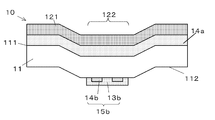
さらに、上記実施形態において、表示部材10は、平板状のものを説明したが、図11に示すように、立体的な形状に設けられても良い。例えば、表示部材10は、圧空成型や絞り成型等で立体的な形状に加工することもできる。なお、立体状の導光部11を用いても良く、これに意匠表示部12、光拡散部13、低屈折率部14a、光調整用低屈折率部14b等を積層することにより、立体的な形状の表示部材10を構成しても良い。(第六実施形態)
本発明は、車両の表示装置に関し、例えば、車速やエンジン回転数などの指標を表示し、その指標を指針が指示することで車両運行状態を把握することができる車両情報表示用の表示装置として適用できる。
10 表示部材
11 導光部
12 意匠表示部
13 光拡散部
13a 表面光拡散部
13b 裏面光拡散部
14a 低屈折率部
14b 光調整用低屈折率部
15 表示光調整部
15a 表面光調整部
15b 裏面光調整部
20 光源
20a 第一の光線
20b 第二の光線
111 導光部の表面
112 導光部の裏面
113 露出面
114 導光部貫通穴
121 不透過部
122 指標部
123 指標部端面領域
124 指標部陰領域
141 貫通孔
11 導光部
12 意匠表示部
13 光拡散部
13a 表面光拡散部
13b 裏面光拡散部
14a 低屈折率部
14b 光調整用低屈折率部
15 表示光調整部
15a 表面光調整部
15b 裏面光調整部
20 光源
20a 第一の光線
20b 第二の光線
111 導光部の表面
112 導光部の裏面
113 露出面
114 導光部貫通穴
121 不透過部
122 指標部
123 指標部端面領域
124 指標部陰領域
141 貫通孔
Claims (2)
- 光源と、前記光源から出射された光を導光する導光部と、前記光が出射する光出射部を有する意匠表示部と、前記導光部と前記意匠表示部との間に設けられ、前記導光部よりも光の屈折率が低い低屈折率部と、前記導光部に形成され前記導光部が導光する前記光を拡散する光拡散部と、を備えた表示装置において、
少なくとも前記光出射部に対応する領域内に、出射効率を変化させる表示光調整部を備えることを特徴とする表示装置。 - 前記表示光調整部は、前記光拡散部と光調整用低屈折率部とによって構成されていることを特徴とする請求項1に記載の表示装置。
Priority Applications (3)
| Application Number | Priority Date | Filing Date | Title |
|---|---|---|---|
| EP11853423.9A EP2660803A4 (en) | 2010-12-28 | 2011-11-09 | DISPLAY DEVICE |
| CN2011800623261A CN103270548A (zh) | 2010-12-28 | 2011-11-09 | 显示装置 |
| US13/977,388 US20130279148A1 (en) | 2010-12-28 | 2011-11-09 | Display device |
Applications Claiming Priority (2)
| Application Number | Priority Date | Filing Date | Title |
|---|---|---|---|
| JP2010291428A JP2012136199A (ja) | 2010-12-28 | 2010-12-28 | 表示装置 |
| JP2010-291428 | 2010-12-28 |
Publications (1)
| Publication Number | Publication Date |
|---|---|
| WO2012090591A1 true WO2012090591A1 (ja) | 2012-07-05 |
Family
ID=46382712
Family Applications (1)
| Application Number | Title | Priority Date | Filing Date |
|---|---|---|---|
| PCT/JP2011/075772 Ceased WO2012090591A1 (ja) | 2010-12-28 | 2011-11-09 | 表示装置 |
Country Status (5)
| Country | Link |
|---|---|
| US (1) | US20130279148A1 (ja) |
| EP (1) | EP2660803A4 (ja) |
| JP (1) | JP2012136199A (ja) |
| CN (1) | CN103270548A (ja) |
| WO (1) | WO2012090591A1 (ja) |
Families Citing this family (9)
| Publication number | Priority date | Publication date | Assignee | Title |
|---|---|---|---|---|
| WO2011109589A2 (en) * | 2010-03-03 | 2011-09-09 | Promising Ground, Llc | Display |
| JP6135921B2 (ja) * | 2013-06-27 | 2017-05-31 | 日本精機株式会社 | 表示部材及び表示装置 |
| US11119263B2 (en) | 2017-06-22 | 2021-09-14 | Xerox Corporation | System and method for image specific illumination of image printed on optical waveguide |
| US20180372630A1 (en) * | 2017-06-22 | 2018-12-27 | Xerox Corporation | System and method for image specific illumination of image printed on optical waveguide |
| US11249240B2 (en) | 2017-06-22 | 2022-02-15 | Xerox Corporation | System and method for image specific illumination of image printed on optical waveguide |
| US10168279B1 (en) | 2017-06-22 | 2019-01-01 | Xerox Corporation | System and method for image specific illumination of image printed on optical waveguide |
| US10539732B2 (en) | 2017-06-22 | 2020-01-21 | Xerox Corporation | System and method for image specific illumination of image printed on optical waveguide |
| US11014497B2 (en) | 2017-07-21 | 2021-05-25 | Weidplas Gmbh | Component for a vehicle |
| JP7088650B2 (ja) | 2017-09-29 | 2022-06-21 | デクセリアルズ株式会社 | 光学体及び発光装置 |
Citations (7)
| Publication number | Priority date | Publication date | Assignee | Title |
|---|---|---|---|---|
| JPS5173445A (ja) | 1974-12-23 | 1976-06-25 | Asahi Chemical Ind | Fuirumujokodotai |
| JPS5287046A (en) | 1976-11-15 | 1977-07-20 | Asahi Chemical Ind | Photoconductor |
| JPS5516587U (ja) * | 1978-07-19 | 1980-02-01 | ||
| JPS5994386U (ja) * | 1982-12-15 | 1984-06-27 | カルソニックカンセイ株式会社 | 透過照明式表示板 |
| JPH04232906A (ja) | 1990-12-28 | 1992-08-21 | Toray Ind Inc | 可撓性多層導光シート及びその製造方法 |
| JPH06235916A (ja) * | 1993-02-08 | 1994-08-23 | Ohtsu Tire & Rubber Co Ltd :The | 導光板装置 |
| JP2010110608A (ja) | 2008-11-10 | 2010-05-20 | Toyohiko Urakawa | 高濃度天然炭酸鉱泉の連続昇温法 |
Family Cites Families (15)
| Publication number | Priority date | Publication date | Assignee | Title |
|---|---|---|---|---|
| JPH0516618Y2 (ja) * | 1988-02-03 | 1993-04-30 | ||
| SG68563A1 (en) * | 1990-09-20 | 1999-11-16 | Illumination Research Group Pr | A display system |
| JP3187280B2 (ja) * | 1995-05-23 | 2001-07-11 | シャープ株式会社 | 面照明装置 |
| TW393582B (en) * | 1995-12-05 | 2000-06-11 | Matsushita Electric Industrial Co Ltd | Backlighting device and color display device |
| JPH10177351A (ja) * | 1996-12-18 | 1998-06-30 | Yazaki Corp | 表示装置 |
| JPH10293212A (ja) * | 1997-02-18 | 1998-11-04 | Dainippon Printing Co Ltd | バックライト及び液晶表示装置 |
| DE19748166A1 (de) * | 1997-10-31 | 1999-05-27 | Preh Elektro Feinmechanik | Lichtleitplatte |
| JP2000346678A (ja) * | 1999-06-07 | 2000-12-15 | Yazaki Corp | 車両用表示装置 |
| JP4048844B2 (ja) * | 2002-06-17 | 2008-02-20 | カシオ計算機株式会社 | 面光源及びそれを用いた表示装置 |
| JP4579146B2 (ja) * | 2005-12-06 | 2010-11-10 | 株式会社 日立ディスプレイズ | 表示装置および面状光源装置 |
| JP4714098B2 (ja) * | 2006-07-06 | 2011-06-29 | 株式会社東海理化電機製作所 | 照明装置 |
| JP2008299117A (ja) * | 2007-05-31 | 2008-12-11 | Fujikura Ltd | 表示装置 |
| CN102047030B (zh) * | 2008-07-10 | 2013-10-30 | 欧姆龙株式会社 | 面光源装置及液晶显示装置 |
| JP4402735B1 (ja) * | 2008-12-16 | 2010-01-20 | ポリマテック株式会社 | キーシート、遮光性導光シート、押釦スイッチおよびキーシートの製造方法 |
| TWI427476B (zh) * | 2009-02-24 | 2014-02-21 | Silicon Motion Inc | 快閃記憶體的存取方法及快閃記憶體裝置 |
-
2010
- 2010-12-28 JP JP2010291428A patent/JP2012136199A/ja active Pending
-
2011
- 2011-11-09 US US13/977,388 patent/US20130279148A1/en not_active Abandoned
- 2011-11-09 WO PCT/JP2011/075772 patent/WO2012090591A1/ja not_active Ceased
- 2011-11-09 CN CN2011800623261A patent/CN103270548A/zh active Pending
- 2011-11-09 EP EP11853423.9A patent/EP2660803A4/en not_active Withdrawn
Patent Citations (7)
| Publication number | Priority date | Publication date | Assignee | Title |
|---|---|---|---|---|
| JPS5173445A (ja) | 1974-12-23 | 1976-06-25 | Asahi Chemical Ind | Fuirumujokodotai |
| JPS5287046A (en) | 1976-11-15 | 1977-07-20 | Asahi Chemical Ind | Photoconductor |
| JPS5516587U (ja) * | 1978-07-19 | 1980-02-01 | ||
| JPS5994386U (ja) * | 1982-12-15 | 1984-06-27 | カルソニックカンセイ株式会社 | 透過照明式表示板 |
| JPH04232906A (ja) | 1990-12-28 | 1992-08-21 | Toray Ind Inc | 可撓性多層導光シート及びその製造方法 |
| JPH06235916A (ja) * | 1993-02-08 | 1994-08-23 | Ohtsu Tire & Rubber Co Ltd :The | 導光板装置 |
| JP2010110608A (ja) | 2008-11-10 | 2010-05-20 | Toyohiko Urakawa | 高濃度天然炭酸鉱泉の連続昇温法 |
Non-Patent Citations (1)
| Title |
|---|
| See also references of EP2660803A4 |
Also Published As
| Publication number | Publication date |
|---|---|
| EP2660803A4 (en) | 2016-01-27 |
| JP2012136199A (ja) | 2012-07-19 |
| US20130279148A1 (en) | 2013-10-24 |
| EP2660803A1 (en) | 2013-11-06 |
| CN103270548A (zh) | 2013-08-28 |
Similar Documents
| Publication | Publication Date | Title |
|---|---|---|
| WO2012090591A1 (ja) | 表示装置 | |
| CN102884568B (zh) | 显示部件和显示装置 | |
| JP5835559B2 (ja) | 指針式表示装置 | |
| WO2010150364A1 (ja) | 照明装置 | |
| JP6223746B2 (ja) | 片面発光タイプの透明な導光板、およびこの導光板を用いた面発光装置 | |
| JPWO2010131735A1 (ja) | 照光表示装置 | |
| CN101718917B (zh) | 显示装置和所述显示装置的前盖 | |
| JP2005257794A (ja) | 表示装置 | |
| JP5196565B2 (ja) | 光源装置及び電子機器 | |
| JP5660380B2 (ja) | 表示装置 | |
| JP3182212U (ja) | 照光表示装置 | |
| JP4434120B2 (ja) | 光源装置 | |
| JP2012013843A (ja) | 表示装置 | |
| JP2013044898A (ja) | 表示装置 | |
| JP2005345548A (ja) | 内照式表示構造及び内照式表示方法 | |
| JP5714887B2 (ja) | バックライト | |
| JP6135921B2 (ja) | 表示部材及び表示装置 | |
| JP5389717B2 (ja) | フロントライト装置および液晶表示装置 | |
| JP2012150069A (ja) | 表示装置 | |
| JP4975604B2 (ja) | 自光式標識構体 | |
| JP2012002850A (ja) | 表示装置 | |
| JP2019029213A (ja) | 面光源装置及びそれを用いた壁部材 | |
| JP2014048067A (ja) | 表示装置 | |
| JP2004205295A (ja) | 指針 | |
| JP2014085260A (ja) | 指針式計器 |
Legal Events
| Date | Code | Title | Description |
|---|---|---|---|
| 121 | Ep: the epo has been informed by wipo that ep was designated in this application |
Ref document number: 11853423 Country of ref document: EP Kind code of ref document: A1 |
|
| NENP | Non-entry into the national phase |
Ref country code: DE |
|
| WWE | Wipo information: entry into national phase |
Ref document number: 13977388 Country of ref document: US |
|
| WWE | Wipo information: entry into national phase |
Ref document number: 2011853423 Country of ref document: EP |