WO2012090949A1 - Feuille réfléchissante - Google Patents
Feuille réfléchissante Download PDFInfo
- Publication number
- WO2012090949A1 WO2012090949A1 PCT/JP2011/080104 JP2011080104W WO2012090949A1 WO 2012090949 A1 WO2012090949 A1 WO 2012090949A1 JP 2011080104 W JP2011080104 W JP 2011080104W WO 2012090949 A1 WO2012090949 A1 WO 2012090949A1
- Authority
- WO
- WIPO (PCT)
- Prior art keywords
- layer
- resin
- porous
- sheet
- laminated
- Prior art date
- Legal status (The legal status is an assumption and is not a legal conclusion. Google has not performed a legal analysis and makes no representation as to the accuracy of the status listed.)
- Ceased
Links
Images
Classifications
-
- G—PHYSICS
- G02—OPTICS
- G02B—OPTICAL ELEMENTS, SYSTEMS OR APPARATUS
- G02B5/00—Optical elements other than lenses
- G02B5/08—Mirrors
- G02B5/0808—Mirrors having a single reflecting layer
Definitions
- the present invention relates to a reflection sheet used as a constituent member of a liquid crystal display device such as a TV or a portable terminal, a lighting fixture, and a lighting signboard.
- reflection sheets have been used in fields such as reflectors for liquid crystal display devices, projection screens and planar light source members, reflectors for lighting fixtures, and reflectors for lighting signs.
- Patent Document 1 proposes a reflection film obtained by adding a fine powder filler such as titanium oxide to an aliphatic polyester resin as a reflection film capable of realizing excellent light reflectivity.
- Patent Document 2 discloses a white polyester film in which fine bubbles are formed in a sheet by stretching a sheet formed by adding a filler to an aromatic polyester resin, thereby causing light diffuse reflection.
- Patent Document 3 discloses a porous sheet obtained by adding an inorganic filler to a polypropylene resin and stretching the polypropylene sheet. These reflective sheets impart optical reflection characteristics by forming pores between the filler and the matrix during stretching.
- Patent Document 4 describes the first and second polymer materials that include at least a first and second different polymer materials that reflect at least 30% of incident light on the object. Including a sufficient number of alternating layers, wherein a substantial majority of each layer of the object has an optical thickness of 0.09 micrometers or less or 0.45 micrometers or more.
- a reflective polymer body having a feature that the refractive indexes of the first and second polymer materials are different from each other by 0.03 or more has been proposed.
- the present invention intends to provide a new reflection sheet that can be reduced in weight and thickness while maintaining sufficient reflection characteristics.
- the present invention includes a porous resin layer A having pores having an average pore diameter of 0.01 ⁇ m or more and less than 1.00 ⁇ m in the major axis direction in the sheet cross section, and an average pore diameter in the major axis direction of the sheet section of 1.00 ⁇ m or more and 10.00 ⁇ m or less.
- the reflective sheet of the present invention exhibits reflection characteristics mainly utilizing light reflection due to the difference in refractive index between the resin and the air in the pores, that is, light reflection due to diffuse reflection. It is possible to easily obtain the reflection characteristics as described above, and it is possible to reduce the weight and thickness while maintaining sufficient reflection characteristics.
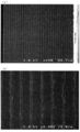
- (A) is the SEM photograph when the cross section of the laminated nonporous film-like material produced in Example 1 is observed at a magnification of 450 times.
- (B) is the SEM photograph when the cross section of the laminated nonporous film-like material produced in Example 1 is observed at a magnification of 2000 times.
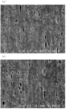
- (A) is a SEM photograph when the cross section of the laminated porous film produced in Example 1 is observed at a magnification of 6000 times.
- (B) is the SEM photograph when the cross section of the lamination
- the present reflective sheet In the reflective sheet according to the present embodiment (referred to as “the present reflective sheet”), a porous resin layer A having many relatively small pores and a porous resin layer B having many relatively large pores are alternately arranged. It is a reflection sheet having a super multi-layer structure formed by laminating. In general, when the hole diameter is large, a high reflectance cannot be obtained, but the reflectance can be obtained from a short wavelength to a long wavelength. On the other hand, if the hole diameter is small, the reflectance on the short wavelength side can be significantly increased.
- the reflectance over 400 to 800 nm can be improved in a well-balanced manner by adjusting the pore diameter, the porosity, and the number of laminated layers of each layer.
- the refractive index of air is 1.0, when holes are formed in the resin layer, light reflection occurs at the interface between the resin and the holes.
- the porous structure in the resin layer greatly affects the optical characteristics.
- the porous resin layer A (hereinafter simply referred to as “A layer”) is a porous resin layer having pores having an average pore diameter in the major axis direction of 0.01 ⁇ m or more and less than 1.00 ⁇ m in the sheet cross section. If the pore size of the A layer is within such a range, the size is suitable for reflecting light in the visible light region (general visible light wavelength region is 380 to 750 nm), and particularly in the visible light wavelength region. In particular, the reflection characteristics of light on the short wavelength side can be improved more effectively.
- the average pore diameter in the major axis direction in the sheet cross section is preferably 0.01 ⁇ m or more and less than 1.00 ⁇ m, more preferably 0.05 ⁇ m or more or 0.80 ⁇ m or less, and particularly 0.10 ⁇ m. It is preferable that it is above or 0.80 ⁇ m.
- the base resin of the A layer that is, the resin constituting the main component is not particularly limited, and for example, a crystalline thermoplastic resin or an amorphous thermoplastic resin can be used.
- thermoplastic resin examples include polyethylene, polypropylene, ionomer, polyethylene terephthalate, polyamide, polyacetal, polybutylene terephthalate, ultrahigh molecular weight polyethylene, polyphenylene sulfide, polyether ether ketone, polytetrafluoroethylene, or a copolymer thereof. And so on.
- amorphous thermoplastic resin examples include polystyrene, rubber-reinforced polystyrene, acrylonitrile-styrene copolymer, acrylonitrile-butadiene-styrene copolymer, styrene-methyl acrylate copolymer, polymethyl acrylate, polymethyl methacrylate, polycarbonate, Polylactic acid, polyvinyl chloride, polyvinylidene chloride, vinyl chloride-ethylene copolymer, vinyl chloride-vinyl acetate copolymer, styrene-isoprene-styrene copolymer, styrene-ethylene / butylene-styrene copolymer, polybutadiene, Polyisoprene, polychloroprene, styrene-butadiene copolymer, ethylene- ⁇ olefin copolymer, ethylene-propylene-diene copoly
- Polypropylene resins include homopolypropylene (propylene homopolymer), or ⁇ such as propylene and ethylene, 1-butene, 1-pentene, 1-hexene, 1-heptene, 1-octene, 1-nonene, 1-decene, etc. Examples thereof include block copolymers with olefins. Among these, homopolypropylene is more preferable in terms of heat resistance and rigidity.
- the polypropylene resin preferably has an isotactic pendant fraction exhibiting stereoregularity of 80 to 99%.
- the isotactic pendant fraction is 80% or more, the mechanical properties of the reflective sheet can be more effectively maintained.
- the upper limit of the isotactic pendant fraction is defined by the upper limit value obtained industrially at present, but this is not the case when more regular resin is developed at the industrial level in the future. is not. From this point of view, the isotactic pendant fraction is more preferably 83 to 98%, and even more preferably 85 to 97%.
- the isotactic pendart fraction is a three-dimensional structure in which all five methyl groups that are side chains are arranged in the same direction with respect to the main chain of carbon-carbon bonds composed of any five consecutive propylene units. It means structure or its proportion.
- Signal assignment of the methyl group region is as follows. Zambelli et at al. (Macromol. 8, 687 (1975)).
- Mw / Mn which is a parameter indicating the molecular weight distribution of the polypropylene-based resin
- Mw / Mn which is a parameter indicating the molecular weight distribution of the polypropylene-based resin
- the extrusion moldability is not deteriorated and it can be produced relatively easily industrially.
- Mw / Mn is 10.0 or less
- the Mw / Mn of the polypropylene resin is preferably 1.5 to 10.0. More preferably, it is 2.0 or more or 8.0 or less, and more preferably 2.0 or more or 6.0 or less.
- Mw / Mn is obtained by GPC (Gel Poe Emission Chromatography) method.
- the melt flow rate (MFR) of the polypropylene resin is usually preferably from 0.5 to 15 g / 10 minutes, and more preferably from 0.6 to 10 g / 10 minutes.
- MFR melt flow rate
- the melt viscosity of the resin at the time of the molding process does not become too high, and a decrease in productivity can be prevented.
- the fall of the mechanical strength of a reflective sheet can be suppressed.
- This MFR is a value measured under conditions of a temperature of 230 ° C. and a load of 2.16 kg in accordance with JIS K7210.
- polypropylene resins examples include trade names “Novatech PP”, “WINTEC” (manufactured by Nippon Polypro), “Versify”, “Inspire” (manufactured by Dow Chemical), “Notio”, “Tuffmer” (Mitsui Chemicals) ), “Zeras”, “Thermorun” (Mitsubishi Chemical), “Sumitomo Noblen”, “Tough Selenium” (Sumitomo Chemical), “Prime TPO” (Prime Polymer), “Adflex”, “Adsyl” Commercially available products such as “HMS-PP (PF814)” (manufactured by Sun Allomer) can be used.
- ⁇ crystal nucleating agent When a polypropylene resin is used as the base resin for the A layer, by adding a ⁇ crystal nucleating agent, the film forming property at the time of molding can be improved, and a thin film having fine pores can be formed more easily. can do.
- the ⁇ crystal nucleating agent that can be used in the present reflective sheet is not particularly limited as long as it increases the formation and growth of ⁇ crystals of polypropylene resin, and two or more types may be mixed and used. it can.
- ⁇ crystal nucleating agents include amide compounds; tetraoxaspiro compounds; quinacridones; iron oxides having a nanoscale size; potassium 1,2-hydroxystearate, magnesium benzoate or magnesium succinate, magnesium phthalate, etc.
- alkali or alkaline earth metal salts of carboxylic acids aromatic sulfonic acid compounds represented by sodium benzene sulfonate or sodium naphthalene sulfonate; di- or triesters of dibasic or tribasic carboxylic acids; phthalocyanine blue Phthalocyanine pigments typified by: a two-component compound comprising a component a which is an organic dibasic acid and a component b which is an oxide, hydroxide or salt of a Group IIA metal of the periodic table; a cyclic phosphorus compound and magnesium Composition consisting of compounds And the like.
- preferable ⁇ crystal nucleating agents include ⁇ crystal nucleating agent “NJESTER NU-100” manufactured by Shin Nippon Rika Co., Ltd., and specific examples of polypropylene resins to which ⁇ crystal nucleating agents are added include polypropylene “ Examples include Bepol B-022SP, Polypropylene “Beta ( ⁇ ) -PP BE60-7032” manufactured by Borealis, and Polypropylene “BNX BETAPP-LN” manufactured by Mayzo. Specific types of other nucleating agents are described in, for example, Japanese Patent Application Laid-Open No. 2003-306585, Japanese Patent Application Laid-Open No. 06-289656, Japanese Patent Application Laid-Open No. 09-194650, and the like.
- the ratio of the ⁇ crystal nucleating agent added to the polypropylene resin needs to be appropriately adjusted depending on the type of the ⁇ crystal nucleating agent or the composition of the polypropylene resin.
- the nucleating agent is preferably 0.0001 to 5.0 parts by mass, more preferably 0.01 parts by mass or more and 3.0 parts by mass or less, and particularly preferably 0.1 parts by mass or more. If the proportion of the ⁇ crystal nucleating agent is 0.0001 parts by mass or more with respect to 100 parts by mass of the polypropylene resin, the ⁇ crystals of the polypropylene resin can be sufficiently produced and grown at the time of production, Air permeability can be obtained. Moreover, if it is 5.0 mass parts or less, it becomes economically advantageous, and since troubles due to bleeding out of the ⁇ crystal nucleating agent are less likely to occur, it is preferable.
- the polypropylene resin is preferably a polypropylene resin other than a random type.
- the porous resin layer B (hereinafter simply referred to as “B layer”) is a porous resin layer having pores having an average pore diameter in the major axis direction of 1.00 ⁇ m to 10.00 ⁇ m in the sheet cross section. If the hole diameter in the cross section of the layer B is within such a range, the size is suitable for reflecting light in the visible light region (general visible light wavelength region is 380 to 750 nm). In particular, the reflection characteristics of light on the long wavelength side of the wavelength region can be improved more effectively.
- the average pore diameter in the major axis direction in the sheet cross section is preferably 1.00 ⁇ m or more and 10.00 ⁇ m or less, more preferably 1.00 ⁇ m or more or 8.00 ⁇ m or less, and more preferably 3.00 ⁇ m or more. Alternatively, it is preferably 8.00 ⁇ m or less.
- the base resin of the B layer that is, the resin constituting the main component is not particularly limited, and for example, a crystalline thermoplastic resin or an amorphous thermoplastic resin can be used.
- the same type of resin as the base resin of the A layer may be used, or a different type of resin may be used.
- the difference between the refractive index of the base resin of the porous resin layer A and the refractive index of the base resin of the porous resin layer B is preferably less than 0.2, particularly less than 0.1, and more preferably 0.03 Preferably it is less than.
- it is a polyethylene-based resin from the viewpoint of easy formation of pores and rigidity.
- the refractive indexes of polypropylene and polyethylene are both 1.5 to 1.6, and the difference between the two is less than 0.03.
- a low-density polyethylene As the polyethylene-based resin used as the base resin of the B layer, a low-density polyethylene, a linear low-density polyethylene, a linear ultra-low-density polyethylene, a medium-density polyethylene, a high-density polyethylene, and a copolymer mainly composed of ethylene, that is, ⁇ -olefins having 3 to 10 carbon atoms such as ethylene and propylene, butene-1, pentene-1, hexene-1, heptene-1 and octene-1; vinyl esters such as vinyl acetate and vinyl propionate; methyl acrylate, A copolymer with one or more comonomers selected from unsaturated carboxylic acid esters such as ethyl acrylate, methyl methacrylate, ethyl methacrylate, and unsaturated compounds such as conjugated dienes and non-conjugated dienes, or A multi-component
- At least one polyethylene resin selected from low-density polyethylene, linear low-density polyethylene, and high-density polyethylene is preferable in terms of ease of formation of pores and rigidity.
- high density polyethylene is most preferable.
- the density of the polyethylene resin is 0.910 ⁇ 0.970g / cm 3, more preferably 0.930 g / cm 3 or more, or 0.970 g / cm 3 or less, 0.94 g / cm it is more preferably 3 or more, or 0.970 g / cm 3 or less.
- a density within the range is preferable because a porous structure can be easily formed.
- the density in the present invention is a value measured according to JIS K7112 using a density gradient tube method.
- the melt flow rate (MFR) of the polyethylene resin is not particularly limited, but usually the MFR is preferably 0.03 to 15 g / 10 min or less, preferably 0.3 g / 10 min or more or 10 g / 10. More preferably, it is less than or equal to minutes. If MFR is the said range, it will not become a problem on extrudability. In addition, this MFR is based on JIS K7210, and is a measured value on condition of temperature 190 degreeC and load 2.16kg.
- the production method of the polyethylene resin is not particularly limited, and a known polymerization method using a known olefin polymerization catalyst, for example, a multi-site catalyst typified by a Ziegler-Natta type catalyst or a single typified by a metallocene catalyst.
- a polymerization method using a site catalyst can be mentioned.
- the ethylene-based copolymer having an MFR (conforming to JIS K7210, temperature: 190 ° C., load: 2.16 kg) of 0.1 g / 10 min to 10 g / 10 min is preferably used. If the MFR is 0.1 g / 10 min or more, the extrudability can be maintained satisfactorily. On the other hand, if the MFR is 10 g / 10 min or less, the strength of the film is hardly lowered.
- ethylene-based copolymer examples include “Evaflex” (manufactured by Mitsui DuPont Polychemical), “Novatech EVA” (manufactured by Nippon Polyethylene), and ethylene-acrylic acid copolymer.
- “NUC Copolymer” (manufactured by Nihon Unicar), “Lex Pearl EAA” (manufactured by Nippon Polyethylene), “Elvalloy” (manufactured by Mitsui DuPont Polychemical Co.) as an ethylene- (meth) -acrylic acid copolymer, “Lex “Pearl EMA” (manufactured by Nippon Polyethylene Co., Ltd.), “Lex Pearl EEA” (manufactured by Nippon Polyethylene Co., Ltd.) as an ethylene-ethyl acrylate copolymer, “Aclift” (manufactured by Sumitomo Chemical Co., Ltd.) as ethylene-methyl (meth) acrylic acid, “Bondyne” as a terpolymer of ethylene-vinyl acetate-maleic anhydride (Sumi (Chemicals Co., Ltd.), ethylene-glycidyl methacrylate copo
- the A layer, the B layer, or both of these layers can contain a thermoplastic resin other than the polyethylene resin.
- the “other thermoplastic resin” include styrene resins such as styrene, AS resin, or ABS resin, ester resins such as fluorine resin, polyethylene terephthalate, polybutylene terephthalate, polycarbonate, and polyarylate; polyacetal, polyphenylene ether, Examples thereof include ether resins such as polysulfone, polyether sulfone, polyether ether ketone, and polyphenylene sulfide; polyamide resins such as 6 nylon, 6-6 nylon, and 6-12 nylon.
- the A layer or the B layer, or both of these layers may contain what is called a rubber component such as a thermoplastic elastomer, if necessary.
- a rubber component such as a thermoplastic elastomer
- examples of the thermoplastic elastomer include styrene / butadiene, polyolefin, urethane, polyester, polyamide, 1,2-polybutadiene, polyvinyl chloride, and ionomer.
- the A layer or the B layer, or both of these layers if necessary, a metal soap as a catalyst neutralizer, a synthetic hydrotalcite compound, and a phenol-based oxidation generally marketed as an antioxidant.
- Antioxidants, phosphorus antioxidants, sulfur antioxidants, antistatic agents such as polyhydric alcohol aliphatic esters, alkyldiethanolamines, linear alkyl alcohols, polyoxyethylene alkylamine fatty acid esters, polyoxyethylene alkylamine compounds, etc.
- a compound comprising one or more selected from the group consisting of hindered amine light stabilizers, weathering agents, antifogging agents, antiblocking agents, and other transparent nucleating agents.
- the A layer or the B layer, or both of these layers may contain other additives or other components as long as the properties of the reflective sheet are not impaired.
- the additive is not particularly limited, but recycled resin generated from trimming loss such as ears, inorganic particles such as silica, talc, kaolin and calcium carbide, pigments such as titanium oxide and carbon black, flame retardants, Weathering stabilizers, antistatic agents, crosslinking agents, lubricants, plasticizers, anti-aging agents, antioxidants, light stabilizers, UV absorbers, neutralizers, antiblocking agents, slip agents, colorants, and other additives Can be mentioned.
- the A layer, the B layer, or both of these layers contain an inorganic filler or an organic filler, and the reflectance can be further increased by the difference in refractive index between these layers and the resin.
- the organic fine powder include cellulose powders such as wood powder and pulp powder, polymer beads, and polymer hollow particles.
- Inorganic fine powders include calcium carbonate, magnesium carbonate, barium carbonate, magnesium sulfate, barium sulfate, calcium sulfate, zinc oxide, magnesium oxide, calcium oxide, titanium oxide, alumina, aluminum hydroxide, hydroxyapatite, silica, mica, talc , Kaolin, clay, glass powder, asbestos powder, zeolite, silicate clay and the like.
- This reflective sheet has a super multi-layer structure in which the A layer and the B layer are alternately laminated from the viewpoint of improving the reflectance from a short wavelength to a long wavelength in a balanced manner, and has at least 25 B layers or more. It is preferable to have a super multi-layer structure, that is, a super multi-layer structure having 50 layers or more in total of the A layer and the B layer. If the A layer and the B layer are alternately laminated so as to have 25 layers or more, it is preferable to reflect the light in the visible light region due to the effect of increasing the scattering effect of the light reflected by the holes in the reflection sheet.
- the B layer so as to have 50 layers or more, particularly 100 layers or more.
- the upper limit of the number of layers is not particularly limited, but is preferably 1000 layers or less from the viewpoint of the thickness of the reflective film.
- the control of the reflectivity by the super multi-layer structure in which a large number of different layers, that is, the A layer and the B layer are laminated utilizes the principle of interference reflection. That is, this is a method of controlling the reflectivity by stacking a large number of thin layers having different refractive indexes and interfering and strengthening the reflected light at the interface between these layers.
- the reflectance can be set by selecting a resin in the resins A and B and adjusting the layer thickness. As described above, when at least 25 layers are stacked, the reflectance ranges from a short wavelength to a long wavelength. The reflectance can be increased in a well-balanced manner.
- the structure in which the A layer and the B layer are alternately stacked preferably has a structure in which the A layer and the B layer are alternately stacked regularly in the thickness direction. That is, it is preferable that the thicknesses of the A layer and the B layer in the reflective sheet are not different, and the thickness of each layer is regular and alternately laminated.
- the stacking ratio of the A layer and the B layer can be appropriately adjusted according to the purpose and is not particularly limited, but the B layer (the total thickness of the B layer) with respect to the total thickness 100
- the ratio is preferably adjusted to 10 to 50, more preferably 15 or more.
- the reflectivity of light in the visible light region (a general visible light wavelength region is 380 to 750 nm) can be sufficiently improved.
- the total thickness of the other layers is preferably 0.01 to 0.05, more preferably 0.01 to 0.03, with respect to the thickness 1 of all layers.
- the reflecting sheet has a porosity of 20.0 to 75.0%.
- the reflection sheet causes light to be reflected at the interface between the resin composition and the holes by forming holes in the resin of each layer, thereby improving the optical reflection characteristics. Therefore, the porosity greatly affects the optical characteristics.
- the porosity of the reflective sheet is within this range, the number of pores in the resin composition is suitable for imparting the property of reflecting light in the visible light region, and the number of interfaces between the resin composition and the pores is suitable. This is preferable because light is sufficiently reflected. More preferably, it is 35.0% or more or 70.0% or less, and particularly preferably 40.0% or more or 65.0% or less.
- the reflection sheet may be flat or tube-shaped, but it is preferable from the viewpoint of productivity that several products can be taken. From the viewpoint of simplicity, a planar shape is more preferable.
- the thickness of the reflective sheet is preferably from 100 ⁇ m to 1 mm, more preferably from 150 ⁇ m to 800 ⁇ m, and even more preferably from 188 ⁇ m to 750 ⁇ m. If the thickness is 150 ⁇ m or more, substantially sufficient optical reflection characteristics can be obtained, and if the thickness is 1 mm or less, substantially sufficient mechanical strength can be obtained.
- the manufacturing method of this reflective sheet is divided roughly into the following three according to the order of perforation and lamination.
- (I) A method of forming a porous layer of A layer and a porous layer of B layer, and then laminating at least the porous layer of A layer and the porous layer of B layer.
- (Ii) A method of producing a non-porous membrane of A layer and B layer and then making the non-porous membrane porous.
- Iii A method in which one of the two layers of the A layer and the B layer is made porous, and then laminated with another layer of a non-porous film to make it porous.
- Examples of the method (i) include a method of thermally laminating the porous layer of layer A and the porous layer of layer B, and a method of laminating with an adhesive or the like.
- a non-porous film of layer A and a non-porous film of layer B are prepared, and the non-porous film of layer A and the non-porous film of layer B are heated.
- Examples thereof include a method of forming a porous layer after laminating with a laminate, an adhesive, or the like, or a method of forming a laminated nonporous film-like material having at least an A layer and a B layer by coextrusion and then forming a porous layer.
- the A layer porous layer and the B layer non-porous membrane material, or the A layer non-porous membrane material and the B layer porous layer are laminated with a thermal laminate or an adhesive.
- the method (b) is preferable from the viewpoint of simplicity of the process and productivity, and a method using coextrusion is more preferable.
- the method for producing the laminated non-porous film-like material is not particularly limited, and a known method such as an extrusion casting method using a T die, a calendar method, an inflation method, or the like can be adopted, but is not particularly limited.
- the extrusion casting method using a T die is preferable from the viewpoints of the film-forming property and stable productivity of the laminated non-porous film.
- the molding temperature in the extrusion casting method using a T-die is appropriately adjusted depending on the flow characteristics and film forming properties of the composition, but is generally higher than the flow start temperature of the composition and lower than the flow start temperature + 100 ° C., preferably the flow start temperature. A range of + 30 ° C. to 80 ° C. is preferred.
- the porosity forming method As a method for making the reflection sheet porous, various known production methods can be applied, and the method is not particularly limited as long as the gist of the present invention is not exceeded. Specific examples of the pore forming method include a chemical foaming method, a physical foaming method, a supercritical foaming method, a stretching method, and an extraction method. Among these, in the present reflective sheet, the stretching method is preferable from the viewpoints of film forming property, continuous productivity, stable productivity, and the like.
- the stretching method include a roll stretching method, a rolling method, a tenter stretching method, and the like.
- the roll stretching method and / or the tenter stretching method in the present invention has a wide selection range of stretching conditions, and therefore a method of stretching them in at least one direction alone or in combination is preferably used.
- the stretching may be performed by a uniaxial stretching method that stretches in the machine direction (MD) by a roll stretching method or the like, a sequential biaxial stretching method that stretches in the transverse direction (TD) by a tenter stretching method after uniaxial stretching in the longitudinal direction, or a tenter.
- Examples thereof include a simultaneous biaxial stretching method in which stretching is performed simultaneously in the longitudinal direction and the transverse direction using a stretching method. From the viewpoint of increasing the reflectance, biaxial stretching is preferable.
- the A layer having an average pore diameter of 0.01 ⁇ m or more and less than 1.00 ⁇ m can be formed.
- a method such as a supercritical foaming method or a stretching method, and in particular, a stretching method using the ⁇ nucleating agent described above. More preferably, it is formed.
- the B layer having an average pore diameter of 1.00 ⁇ m or more and less than 10.00 ⁇ m can also be formed by the above-described porous method.
- This reflective sheet can also form a metal thin film layer on the back side of the sheet (that is, the side opposite to the reflective surface).
- the metal thin film layer can be formed by depositing a metal, and can be formed by, for example, a vacuum deposition method, an ionization deposition method, a sputtering deposition method, an ion plating method, or the like.
- a vacuum deposition method As the vapor deposition metal material, any material having a high reflectance can be used without any particular limitation. In general, silver, aluminum, and the like are preferable, and among these, silver is preferable from the viewpoint of optical reflection characteristics. Is particularly preferred.
- the metal thin film layer may be a metal single layer product or a laminate product, or a metal oxide single layer product or a laminate product of two or more layers of a metal single layer product and a metal oxide single layer product. But you can.
- the thickness of the metal thin film layer varies depending on the layer forming method and the like, but usually it is preferably in the range of 10 nm to 300 nm, and more preferably in the range of 20 nm to 200 nm. A thickness of the metal thin film layer of 300 nm is preferable because production efficiency is good.
- the metal thin film layer may be formed on the reflection sheet by metal vapor deposition.
- a film in which a metal thin film layer is formed on an intermediate layer made of a resin film or the like is prepared in advance, and this film is made of a polystyrene-based resin porous film. And may be laminated.
- the metal thin film layer and the reflection sheet of the produced film can be laminated, or the intermediate layer and the reflection sheet of the produced film can be simply laminated.
- a bonding method a method of bonding by a known method using various adhesives, a known thermal bonding method, or the like can be used.
- Examples of the layer structure in the case of having such a metal thin film layer include: reflection sheet / (optional anchor coat layer) / metal thin film layer / protective layer layer structure, or polystyrene-based resin porous film / intermediate layer / (If necessary, an anchor coat layer) / metal thin film layer / protective layer layer structure and the like can be mentioned.
- the polystyrene resin porous film is preferably disposed on the side irradiated with light.
- you may have another layer between these layers, and a reflective sheet, a metal thin film layer, etc. may each comprise multiple separately.
- the reflection sheet can be formed by covering the reflection sheet with a metal plate or a resin plate.
- This reflector is useful as a reflector used in liquid crystal display devices, lighting equipment, lighting signs, and the like. An example of how to manufacture such a reflector will be described.
- a method of coating the reflective sheet on a metal plate or a resin plate a method using an adhesive, a method of heat-sealing without using an adhesive, a method of bonding via an adhesive sheet, a method of extrusion coating, etc.
- an adhesive such as polyester, polyurethane, or epoxy can be applied to the surface of the metal plate or resin plate on the side where the reflection sheet is bonded, and the reflection sheet can be bonded.
- a commonly used coating facility such as a reverse roll coater or a kiss roll coater is used, and the adhesive film thickness after drying on the surface of a metal plate or the like to which the reflective sheet is bonded is about 2 to 4 ⁇ m.
- the expression “main component” includes the intention to allow other components to be contained within a range that does not interfere with the function of the main component, unless otherwise specified. Although the content ratio is not specified, the main component includes the meaning of occupying 50% by mass or more, preferably 70% by mass or more, particularly preferably 90% by mass or more (including 100% by mass) in the composition. It is.
- X is preferably greater than X” or “preferably smaller than Y”, with the meaning of “X to Y” unless otherwise specified. Is also included.
- X or more is an arbitrary number
- Y or less is an arbitrary number
- the various measured values and evaluation about the reflective sheet displayed in this specification were performed as follows.
- the take-off (flow) direction of the reflection sheet from the extruder is referred to as the vertical direction (MD)
- the orthogonal direction is referred to as the horizontal direction (TD).
- NOVATEC PP FY6HA manufactured by Nippon Polypro Co., Ltd., refractive index 1.51, MFR: 2 g / 10 min
- high density polyethylene (“Novatec HD HF560” manufactured by Nippon Polytechnic Co., Ltd., density: 0.963 g / cm 3 , refractive index 1.53, MFR: 7.0 g / 10 min. ) was used as the resin composition B1.
- Resin compositions A1 and B1 were extruded at 200 ° C. with separate extruders, and A1 / B1 / A1 / B1 /... / A1 so that the A1 layer would be the front and back through a 65-layer feed block.
- Split extrusion was then performed at 200 ° C. from a single-layer fishtail die having a base width of 300 mm and a lip gap of 2 mm.
- a cross-sectional SEM photograph of the laminated non-porous membrane is shown in FIG.
- the thickness of the A1 layer of the laminated non-porous film was about 6.0 ⁇ m, and the thickness of the B1 layer was about 1.5 ⁇ m.
- the laminated nonporous film-like material was stretched 1.5 times in the machine direction at 20 to 100 ° C. by a roll stretching machine, and then stretched 3.0 times in the machine direction at 100 ° C., and the total machine draw ratio was 4.
- a laminated porous film having a thickness of 35 ⁇ m was produced by sequentially biaxially stretching 2.75 times at 100 ° C. in the transverse direction with a tenter stretching machine.
- the obtained laminated porous film was superposed by a dry lamination method to obtain a reflective sheet having a thickness of 175 ⁇ m and a laminated number of 325 layers (B layer number 160).
- Table 1 An SEM photograph of the cross section of the laminated porous film is shown in FIG.
- Example 2 A laminated nonporous membrane having a thickness of 250 ⁇ m was obtained in the same manner as in Example 1 until the laminated nonporous membrane was obtained.
- the laminated film-like material is stretched by a roll stretching machine at 120 ° C. so as to be 3 times in the longitudinal direction, and then is sequentially biaxially stretched 3.0 times in the transverse direction at 100 ° C. so that the thickness becomes 115 ⁇ m.
- a porous film was prepared, and the obtained laminated porous films were laminated by a dry lamination method to obtain a reflective sheet having a thickness of 315 ⁇ m and a number of laminated layers of 195 layers (number of B layers: 96). The results are summarized in Table 1.
- Example 3 A laminated nonporous membrane having a thickness of 250 ⁇ m was obtained in the same manner as in Example 1 until the laminated nonporous membrane was obtained.
- the obtained laminated film was stretched 1.5 times in the machine direction at 20 to 120 ° C. with a roll stretching machine, and then stretched 4.0 times in the machine direction at 120 ° C., for a total machine draw ratio of 6.
- a laminated porous film having a thickness of 45 ⁇ m is prepared by longitudinal stretching so as to be 0 times, and the obtained laminated porous films are laminated by a dry lamination method, and the thickness is 450 ⁇ m and the number of laminated layers is 650.
- a reflective sheet having a layer (number of B layers: 320) was obtained.
- Example 4 A laminated nonporous membrane was obtained in the same manner as in Example 1 except that the thickness of the laminated nonporous membrane was adjusted to 95 ⁇ m by adjusting the film forming conditions, that is, the extrusion amount and the molding speed.
- the SEM photograph of the cross section of the obtained laminated non-porous membrane is shown in FIG.
- the thickness of the A1 layer of the laminated non-porous film is about 1.8 ⁇ m
- the thickness of the B1 layer is about 0.6 ⁇ m.
- the obtained laminated non-porous film-like material was stretched 4.0 times in multiple stages in the longitudinal direction at 80 ° C. with a roll stretching machine, and then sequentially biaxially stretched 2.0 times in the transverse direction at 100 ° C.
- a laminated porous film having a thickness of 36 ⁇ m was prepared.
- the obtained laminated porous film was laminated by a dry lamination method to obtain a reflective sheet having a thickness of 360 ⁇ m and a laminated number of 650 layers (B layer number 320).
- Example 5 A laminated non-porous membrane part was obtained in the same manner as in Example 1 except that the thickness of the laminated non-porous membrane was adjusted to 95 ⁇ m by adjusting the film forming conditions, that is, the extrusion amount and the molding speed.
- the obtained laminated non-porous membrane was longitudinally stretched 4.0 times in multiple stages in the longitudinal direction at 80 ° C. with a roll stretching machine to prepare a laminated porous film having a thickness of 50 ⁇ m.
- the obtained laminated porous film was laminated by a dry lamination method to obtain a reflective sheet having a thickness of 500 ⁇ m and a number of laminated layers of 650 layers (number of B layers: 320). At this time, the alignment directions were aligned.
- Resin composition A1 was obtained in the same manner as in Example 1. Except that the obtained resin composition A1 was extruded at 200 ° C. with a separate extruder and divided and extruded through a 65-layer feed block so as to be A1 / A1 / A1... / A1.
- a laminated nonporous film-like material having a thickness of 250 ⁇ m and a thickness of 250 ⁇ m was obtained.
- a laminated porous film having a thickness of 80 ⁇ m was prepared from the obtained laminated film-like material only of A1 under the same stretching conditions as in Example 2, and the obtained laminated porous film was obtained by a dry lamination method with three sheets. By superposing them, a laminated porous film having a thickness of 240 ⁇ m and substantially only A1 was obtained. It can be confirmed that the obtained reflection sheet of substantially only A1 has a reflectance lower than that of the film of Example 2.
- Example 2 In the same manner as in Example 1, the resin composition B1 was extruded at 200 ° C. with a separate extruder and divided into B1 / B1 / B1... / B1 through a 65-layer feed block. Except for the extrusion, a laminated nonporous film-like material having a thickness of only 250 ⁇ m and a thickness of 250 ⁇ m was obtained in the same manner as in Example 1. The obtained laminated film-like material substantially containing only B1 was tried to be stretched under the same stretching conditions as in Example 2. However, the film was broken during stretching and a porous film could not be obtained.
- the reflective sheets of Examples 1 to 6 had a reflectance of 96% or more and were excellent in optical reflection characteristics.
- the porous sheet (Comparative Example 1) having substantially only the A layer did not exhibit desired reflection characteristics. From the above examples and the results of the tests conducted so far, the average pore diameter in the sheet cross section of the porous resin layer A having pores of 0.01 ⁇ m or more and less than 1.00 ⁇ m, and the average of the long diameter direction in the sheet cross section A reflective sheet having a configuration in which a large number of porous resin layers B having pores having a pore diameter of 1.00 ⁇ m or more and 10.00 ⁇ m or less are alternately laminated, and the porosity of the entire sheet is 20.0 to 75 If it is 0.0%, it can be considered that the desired reflection characteristics can be obtained, and that the weight and thickness can be reduced. In addition, regarding the number of layers, from the above examples and the results of the tests conducted so far, if the layer B has at least 25 layers, the same effect as the
Landscapes
- Physics & Mathematics (AREA)
- General Physics & Mathematics (AREA)
- Optics & Photonics (AREA)
- Optical Elements Other Than Lenses (AREA)
- Laminated Bodies (AREA)
Abstract
L'invention concerne une nouvelle feuille réfléchissante présentant une épaisseur et un poids réduits tout en ayant des caractéristiques de réflexion suffisantes. La feuille réfléchissante possède une configuration dans laquelle des couches de résine poreuses (A), qui ont un diamètre des pores moyen supérieur ou égal à 0,01 μm mais inférieur à 1,00 μm dans le sens du diamètre long dans la section de la feuille, et des couches de résine poreuses (B), qui ont un diamètre des pores moyen d'au moins 1,00 μm mais ne dépassant pas 10,00 μm dans le sens du diamètre long dans la section de la feuille, sont stratifiées de manière alternée. La feuille réfléchissante est caractérisée en ce que la porosité de toute la feuille est de 20-75%.
Priority Applications (1)
| Application Number | Priority Date | Filing Date | Title |
|---|---|---|---|
| JP2012550942A JP6017962B2 (ja) | 2010-12-28 | 2011-12-26 | 反射シート |
Applications Claiming Priority (2)
| Application Number | Priority Date | Filing Date | Title |
|---|---|---|---|
| JP2010293992 | 2010-12-28 | ||
| JP2010-293992 | 2010-12-28 |
Publications (1)
| Publication Number | Publication Date |
|---|---|
| WO2012090949A1 true WO2012090949A1 (fr) | 2012-07-05 |
Family
ID=46383049
Family Applications (1)
| Application Number | Title | Priority Date | Filing Date |
|---|---|---|---|
| PCT/JP2011/080104 Ceased WO2012090949A1 (fr) | 2010-12-28 | 2011-12-26 | Feuille réfléchissante |
Country Status (2)
| Country | Link |
|---|---|
| JP (1) | JP6017962B2 (fr) |
| WO (1) | WO2012090949A1 (fr) |
Cited By (4)
| Publication number | Priority date | Publication date | Assignee | Title |
|---|---|---|---|---|
| JP2014065199A (ja) * | 2012-09-25 | 2014-04-17 | Sumitomo Bakelite Co Ltd | 多層フィルムおよび包装体 |
| JP2014180853A (ja) * | 2013-03-21 | 2014-09-29 | Sumitomo Bakelite Co Ltd | 多層フィルムおよび包装体 |
| JP2018525669A (ja) * | 2015-07-24 | 2018-09-06 | スリーエム イノベイティブ プロパティズ カンパニー | 熱拡散層を有する反射性積層体 |
| CN115047551A (zh) * | 2022-08-15 | 2022-09-13 | 深圳市光科全息技术有限公司 | 白色反射膜及其制备方法、投影幕布 |
Citations (3)
| Publication number | Priority date | Publication date | Assignee | Title |
|---|---|---|---|---|
| JP2003136619A (ja) * | 2001-10-31 | 2003-05-14 | Toray Ind Inc | 微細気泡含有フィルム |
| JP2005054176A (ja) * | 2003-07-18 | 2005-03-03 | Oji Paper Co Ltd | シート状発泡体およびその製造方法 |
| JP2008107804A (ja) * | 2006-09-26 | 2008-05-08 | Toray Ind Inc | 光反射フィルム |
Family Cites Families (4)
| Publication number | Priority date | Publication date | Assignee | Title |
|---|---|---|---|---|
| JP2004341067A (ja) * | 2003-05-13 | 2004-12-02 | Mitsui Chemicals Inc | 反射体、それを用いた照明装置および表示装置 |
| JP4923378B2 (ja) * | 2003-05-16 | 2012-04-25 | 東レ株式会社 | 光反射フィルムおよびその製造方法 |
| DE602004022688D1 (de) * | 2003-10-17 | 2009-10-01 | Mitsubishi Plastics Inc | Reflektierender film |
| JP2010224446A (ja) * | 2009-03-25 | 2010-10-07 | Teijin Dupont Films Japan Ltd | 液晶表示装置のバックライトユニットの反射フィルム用白色フィルム |
-
2011
- 2011-12-26 WO PCT/JP2011/080104 patent/WO2012090949A1/fr not_active Ceased
- 2011-12-26 JP JP2012550942A patent/JP6017962B2/ja active Active
Patent Citations (3)
| Publication number | Priority date | Publication date | Assignee | Title |
|---|---|---|---|---|
| JP2003136619A (ja) * | 2001-10-31 | 2003-05-14 | Toray Ind Inc | 微細気泡含有フィルム |
| JP2005054176A (ja) * | 2003-07-18 | 2005-03-03 | Oji Paper Co Ltd | シート状発泡体およびその製造方法 |
| JP2008107804A (ja) * | 2006-09-26 | 2008-05-08 | Toray Ind Inc | 光反射フィルム |
Cited By (7)
| Publication number | Priority date | Publication date | Assignee | Title |
|---|---|---|---|---|
| JP2014065199A (ja) * | 2012-09-25 | 2014-04-17 | Sumitomo Bakelite Co Ltd | 多層フィルムおよび包装体 |
| JP2014180853A (ja) * | 2013-03-21 | 2014-09-29 | Sumitomo Bakelite Co Ltd | 多層フィルムおよび包装体 |
| JP2018525669A (ja) * | 2015-07-24 | 2018-09-06 | スリーエム イノベイティブ プロパティズ カンパニー | 熱拡散層を有する反射性積層体 |
| US11125921B2 (en) | 2015-07-24 | 2021-09-21 | 3M Innovative Properties Company | Reflective stack with heat spreading layer |
| US11726238B2 (en) | 2015-07-24 | 2023-08-15 | 3M Innovative Properties Company | Reflective stack with heat spreading layer |
| CN115047551A (zh) * | 2022-08-15 | 2022-09-13 | 深圳市光科全息技术有限公司 | 白色反射膜及其制备方法、投影幕布 |
| CN115047551B (zh) * | 2022-08-15 | 2022-11-29 | 深圳市光科全息技术有限公司 | 白色反射膜及其制备方法、投影幕布 |
Also Published As
| Publication number | Publication date |
|---|---|
| JP6017962B2 (ja) | 2016-11-02 |
| JPWO2012090949A1 (ja) | 2014-06-05 |
Similar Documents
| Publication | Publication Date | Title |
|---|---|---|
| JP5887880B2 (ja) | 発泡積層体の製造方法及びその発泡積層体 | |
| TWI364446B (en) | Surface protective film | |
| CN1330983C (zh) | 光反射体 | |
| JP7423786B2 (ja) | 積層フィルム | |
| JP6017962B2 (ja) | 反射シート | |
| JP2004309804A (ja) | 光反射体 | |
| JP6886797B2 (ja) | 二軸延伸つや消し調ポリプロピレン系フィルム及びこれを用いた印刷フィルム | |
| JP6093975B2 (ja) | 発泡積層体の製造方法及びその発泡積層体 | |
| JP6897338B2 (ja) | 発泡用積層体及び発泡積層体 | |
| JP6331348B2 (ja) | 発泡積層体の製造方法及びその発泡積層体 | |
| JP6123211B2 (ja) | 発泡積層体 | |
| JP6878838B2 (ja) | 発泡用積層体及び発泡積層体 | |
| KR101154590B1 (ko) | 폴리프로필렌계 필름 및 그 제조 방법 | |
| JP6326778B2 (ja) | 発泡積層体の製造方法及びその発泡積層体 | |
| JP4578075B2 (ja) | 光反射体 | |
| JP5050911B2 (ja) | 加熱発泡用積層体および発泡体 | |
| JP2005099314A (ja) | 光反射体およびそれを用いた両面表示型面光源装置 | |
| JP2014214488A (ja) | 樹脂発泡体用熱ラミネート用フィルム及び建材 | |
| JP2013252645A (ja) | 二軸延伸多層ポリプロピレンフィルム | |
| JP6747114B2 (ja) | 発泡用積層体及び発泡積層体 | |
| JP2007044930A (ja) | 二軸延伸多層プロピレン系重合体フィルム | |
| KR20190139833A (ko) | 실런트 필름 및 포장재 | |
| JP7292884B2 (ja) | 表面保護フィルム | |
| JP6672633B2 (ja) | 反射シート及び反射板 | |
| JP3621999B2 (ja) | 積層体の製造法 |
Legal Events
| Date | Code | Title | Description |
|---|---|---|---|
| 121 | Ep: the epo has been informed by wipo that ep was designated in this application |
Ref document number: 11854327 Country of ref document: EP Kind code of ref document: A1 |
|
| ENP | Entry into the national phase |
Ref document number: 2012550942 Country of ref document: JP Kind code of ref document: A |
|
| NENP | Non-entry into the national phase |
Ref country code: DE |
|
| 122 | Ep: pct application non-entry in european phase |
Ref document number: 11854327 Country of ref document: EP Kind code of ref document: A1 |