WO2012091102A1 - 風力発電装置の制御装置、風力発電システム、及び風力発電装置の制御方法 - Google Patents
風力発電装置の制御装置、風力発電システム、及び風力発電装置の制御方法 Download PDFInfo
- Publication number
- WO2012091102A1 WO2012091102A1 PCT/JP2011/080421 JP2011080421W WO2012091102A1 WO 2012091102 A1 WO2012091102 A1 WO 2012091102A1 JP 2011080421 W JP2011080421 W JP 2011080421W WO 2012091102 A1 WO2012091102 A1 WO 2012091102A1
- Authority
- WO
- WIPO (PCT)
- Prior art keywords
- power
- generator
- wind
- frequency
- wind turbine
- Prior art date
- Legal status (The legal status is an assumption and is not a legal conclusion. Google has not performed a legal analysis and makes no representation as to the accuracy of the status listed.)
- Ceased
Links
Images

Classifications
-
- F—MECHANICAL ENGINEERING; LIGHTING; HEATING; WEAPONS; BLASTING
- F03—MACHINES OR ENGINES FOR LIQUIDS; WIND, SPRING, OR WEIGHT MOTORS; PRODUCING MECHANICAL POWER OR A REACTIVE PROPULSIVE THRUST, NOT OTHERWISE PROVIDED FOR
- F03D—WIND MOTORS
- F03D7/00—Controlling wind motors
- F03D7/02—Controlling wind motors the wind motors having rotation axis substantially parallel to the air flow entering the rotor
- F03D7/028—Controlling wind motors the wind motors having rotation axis substantially parallel to the air flow entering the rotor controlling wind motor output power
- F03D7/0284—Controlling wind motors the wind motors having rotation axis substantially parallel to the air flow entering the rotor controlling wind motor output power in relation to the state of the electric grid
-
- F—MECHANICAL ENGINEERING; LIGHTING; HEATING; WEAPONS; BLASTING
- F03—MACHINES OR ENGINES FOR LIQUIDS; WIND, SPRING, OR WEIGHT MOTORS; PRODUCING MECHANICAL POWER OR A REACTIVE PROPULSIVE THRUST, NOT OTHERWISE PROVIDED FOR
- F03D—WIND MOTORS
- F03D7/00—Controlling wind motors
- F03D7/02—Controlling wind motors the wind motors having rotation axis substantially parallel to the air flow entering the rotor
- F03D7/04—Automatic control; Regulation
-
- F—MECHANICAL ENGINEERING; LIGHTING; HEATING; WEAPONS; BLASTING
- F03—MACHINES OR ENGINES FOR LIQUIDS; WIND, SPRING, OR WEIGHT MOTORS; PRODUCING MECHANICAL POWER OR A REACTIVE PROPULSIVE THRUST, NOT OTHERWISE PROVIDED FOR
- F03D—WIND MOTORS
- F03D9/00—Adaptations of wind motors for special use; Combinations of wind motors with apparatus driven thereby; Wind motors specially adapted for installation in particular locations
- F03D9/20—Wind motors characterised by the driven apparatus
- F03D9/25—Wind motors characterised by the driven apparatus the apparatus being an electrical generator
- F03D9/255—Wind motors characterised by the driven apparatus the apparatus being an electrical generator connected to electrical distribution networks; Arrangements therefor
-
- H—ELECTRICITY
- H02—GENERATION; CONVERSION OR DISTRIBUTION OF ELECTRIC POWER
- H02P—CONTROL OR REGULATION OF ELECTRIC MOTORS, ELECTRIC GENERATORS OR DYNAMO-ELECTRIC CONVERTERS; CONTROLLING TRANSFORMERS, REACTORS OR CHOKE COILS
- H02P9/00—Arrangements for controlling electric generators for the purpose of obtaining a desired output
-
- H—ELECTRICITY
- H02—GENERATION; CONVERSION OR DISTRIBUTION OF ELECTRIC POWER
- H02P—CONTROL OR REGULATION OF ELECTRIC MOTORS, ELECTRIC GENERATORS OR DYNAMO-ELECTRIC CONVERTERS; CONTROLLING TRANSFORMERS, REACTORS OR CHOKE COILS
- H02P9/00—Arrangements for controlling electric generators for the purpose of obtaining a desired output
- H02P9/007—Control circuits for doubly fed generators
-
- F—MECHANICAL ENGINEERING; LIGHTING; HEATING; WEAPONS; BLASTING
- F05—INDEXING SCHEMES RELATING TO ENGINES OR PUMPS IN VARIOUS SUBCLASSES OF CLASSES F01-F04
- F05B—INDEXING SCHEME RELATING TO WIND, SPRING, WEIGHT, INERTIA OR LIKE MOTORS, TO MACHINES OR ENGINES FOR LIQUIDS COVERED BY SUBCLASSES F03B, F03D AND F03G
- F05B2240/00—Components
- F05B2240/20—Rotors
- F05B2240/21—Rotors for wind turbines
- F05B2240/221—Rotors for wind turbines with horizontal axis
-
- F—MECHANICAL ENGINEERING; LIGHTING; HEATING; WEAPONS; BLASTING
- F05—INDEXING SCHEMES RELATING TO ENGINES OR PUMPS IN VARIOUS SUBCLASSES OF CLASSES F01-F04
- F05B—INDEXING SCHEME RELATING TO WIND, SPRING, WEIGHT, INERTIA OR LIKE MOTORS, TO MACHINES OR ENGINES FOR LIQUIDS COVERED BY SUBCLASSES F03B, F03D AND F03G
- F05B2270/00—Control
- F05B2270/30—Control parameters, e.g. input parameters
- F05B2270/337—Electrical grid status parameters, e.g. voltage, frequency or power demand
-
- H—ELECTRICITY
- H02—GENERATION; CONVERSION OR DISTRIBUTION OF ELECTRIC POWER
- H02P—CONTROL OR REGULATION OF ELECTRIC MOTORS, ELECTRIC GENERATORS OR DYNAMO-ELECTRIC CONVERTERS; CONTROLLING TRANSFORMERS, REACTORS OR CHOKE COILS
- H02P2101/00—Special adaptation of control arrangements for generators
- H02P2101/15—Special adaptation of control arrangements for generators for wind-driven turbines
-
- Y—GENERAL TAGGING OF NEW TECHNOLOGICAL DEVELOPMENTS; GENERAL TAGGING OF CROSS-SECTIONAL TECHNOLOGIES SPANNING OVER SEVERAL SECTIONS OF THE IPC; TECHNICAL SUBJECTS COVERED BY FORMER USPC CROSS-REFERENCE ART COLLECTIONS [XRACs] AND DIGESTS
- Y02—TECHNOLOGIES OR APPLICATIONS FOR MITIGATION OR ADAPTATION AGAINST CLIMATE CHANGE
- Y02E—REDUCTION OF GREENHOUSE GAS [GHG] EMISSIONS, RELATED TO ENERGY GENERATION, TRANSMISSION OR DISTRIBUTION
- Y02E10/00—Energy generation through renewable energy sources
- Y02E10/70—Wind energy
- Y02E10/72—Wind turbines with rotation axis in wind direction
Definitions
- the present invention relates to a wind turbine generator control device, a wind turbine generator system, and a wind turbine generator control method.
- Patent Document 1 describes that in PFR, the active power to be output is limited based on the rotational speed of the rotor and the power generation output.
- the PFR generally increases or decreases the power generation output of the wind power generator according to the deviation (frequency change amount) between the set frequency and the actual frequency (measured value), but the wind power generator uses natural energy that is not constant as a power source. Then, the rotational speed of the rotor may fluctuate significantly as compared with a turbine generator (synchronous generator) that uses a stable controllable energy such as gas combustion or steam.
- the PFR required amount which is an additional power generation output required for performing PFR
- the rotational speed of the rotor may fall below the disconnection lower limit, and the wind power generator may be disconnected.
- the number of rotations of the rotor may exceed the overspeed upper limit, and the wind turbine generator may trip (cut off of output). .
- the case of tripping may occur due to over-rotation of the rotor, over-output, or over-current.
- Such a disconnection or trip of the wind power generation apparatus during the execution of PFR acts as a disturbance to the power system, which may make the frequency of the power system more unstable than when PFR is not performed. . Moreover, since it takes time to restart once it trips, the wind turbine generator cannot achieve the purpose of restoring the frequency of the power system.
- An object of the present invention is to provide a wind turbine generator control device, a wind turbine generator system, and a wind turbine generator control method that can be prevented.
- the following means are employed in the wind turbine generator control apparatus, wind turbine generator system, and wind turbine generator control method of the present invention.
- a rotor having a plurality of blades rotates by receiving wind
- the generator generates power by the rotation of the rotor, and supplies power to the power system
- a wind turbine generator control device capable of changing an amount of power supplied to the power grid in accordance with a change in frequency of the power grid, the measured value of the frequency of the power generation output of the wind turbine generator, and the wind power generator
- a calculation means for calculating a frequency change amount that is a difference from a set value of the frequency of the power generation output of the device, and a power change amount according to the frequency change amount calculated by the calculation means as a rotation speed of the generator.
- Limiting means for limiting based on.
- a rotor having a plurality of blades receives wind to rotate, the generator generates electricity by rotation of the rotor, and supplies power to an electric power system.
- a wind power generator capable of changing the amount of power supplied to the power system in accordance with fluctuations in the frequency of the power system is controlled.
- the control device of the wind turbine generator is configured such that the calculation means causes the frequency that is the difference between the measured value of the power generation output frequency of the wind turbine generator and the set value of the frequency of the power generation output of the wind turbine generator.
- the amount of change is calculated.
- the amount of frequency change is the difference between the frequency of the power generation output required by the wind turbine generator and the frequency of the actual power generation output.
- the control means recovers the change.
- the set value for the is input. That is, when a frequency variation occurs in the power system, the calculation means calculates the amount of change in the frequency required to recover the frequency variation in the power system.
- the limiting means limits the power change amount according to the frequency change amount calculated by the calculating means based on the number of revolutions of the generator.
- the rotation of the rotor may be equal to or less than the rotation speed at which the wind turbine generator is disconnected from the power system. Further, the rotation of the rotor may exceed the overspeed upper limit, and the wind turbine generator may trip. Wind power plant disconnects and trips may not only contribute to the recovery of power system frequency fluctuations, but may also make the power system frequency more unstable.
- the rotational speed of the generator has a relationship with the rotational speed of the rotor. When the rotational speed of the generator is low, the rotational speed of the rotor is low, and when the rotational speed of the generator is high, the rotational speed of the rotor is high.
- the wind turbine generator control device recovers fluctuations in the frequency of the power system by limiting the power change amount according to the frequency change amount based on the rotation speed of the generator. Therefore, it can be prevented that the increase or decrease of the power generation output becomes excessive, and the wind power generation apparatus cannot supply power to the power system.
- the limiting means sets the power change amount to a predetermined first limit value when the rotational speed of the generator is equal to or less than a first set value.
- the amount of change in power is set to a predetermined second limit value that is larger than the first limit value, and the rotational speed of the generator is the first
- the limit value of the power change amount may be increased between the first limit value and the second limit value as the number of revolutions of the generator increases.
- the power change amount is set to the first limit value, and when the rotation speed of the generator is equal to or higher than the second set value.
- the power change amount is a predetermined second limit value that is greater than the first limit value.
- the limit value of the power change amount increases from the first limit value to the second limit as the generator speed increases. Raised between limits.
- the case where the rotational speed of the generator is equal to or lower than the first set value is a case where the rotational speed of the rotor is lower, and when trying to output more power than the current state, the rotational speed of the rotor becomes too low.
- the power generation output of the wind turbine generator may be lower than the lower limit of disconnection.
- a first limit value is provided for the power change amount to prevent the wind power generator from being disconnected.
- the case where the number of revolutions of the generator is equal to or greater than the second set value is a case where the number of revolutions of the rotor is higher, and the wind power generator may trip if an attempt is made to output more power than the current state. This is the case.
- a second limit value is provided for the amount of change in power to prevent the wind power generator from tripping.
- the limit value of the power change amount is increased as the generator rotational speed is increased.
- the amount of power change is limited by the corresponding limit value.
- control device for a wind turbine generator having the above configuration more reliably ensures that the power generation output increases or decreases excessively when recovering the frequency fluctuation of the power grid, and the wind turbine generator cannot supply power to the grid. Can be prevented.
- the limiting means multiplies the power change amount by a predetermined gain, and the predetermined gain is equal to or less than a first set value.
- the first gain is set, and when the rotational speed of the generator is equal to or higher than the second set value, the second gain is set.
- the rotational speed of the generator exceeds the first set value, the rotational speed of the generator is increased. It is good also as a structure which raises to the 3rd gain higher than the said 1st gain and the said 2nd gain with a raise, and when it reaches this 3rd gain, it falls to the said 2nd gain until it reaches the said 2nd setting value.
- the gain multiplied by the power change amount by the limiting unit is set to the first gain when the rotational speed of the generator is equal to or lower than the first set value, and the rotational speed of the generator is set to the second set value.
- the second gain is set. That is, by setting the first gain and the second gain to be small (for example, 0 (zero)), the amount of power change is reduced. This prevents the rotor speed from becoming too low and the power generation output from becoming too high.
- the gain increases to a third gain that is higher than the first gain and the second gain as the rotational speed of the generator increases.
- the third gain is set to decrease to the second gain.
- control device for a wind turbine generator having the above configuration more reliably ensures that the power generation output increases or decreases excessively when recovering the frequency fluctuation of the power grid, and the wind turbine generator cannot supply power to the grid. Can be prevented.
- the control device for a wind turbine generator according to the first aspect may be configured such that the limiting means corrects the power change amount based on the acceleration of the rotation of the generator.
- the power change amount is corrected based on the acceleration of the generator rotation obtained from the differential value of the generator rotation speed. That is, the amount of power change is corrected according to the deceleration and acceleration of the rotational speed.
- control device for a wind turbine generator having the above configuration more reliably ensures that the power generation output increases or decreases excessively when recovering the frequency fluctuation of the power grid, and the wind turbine generator cannot supply power to the grid. Can be prevented.
- the power generation output of the wind turbine generator is based on the speed of the generator, the measured value of the frequency, and the wind speed with respect to the wind turbine generator. It is good also as a structure which estimates the fluctuation amount of the wind speed with respect to the said frequency and the said wind power generator, and correct
- the variation in the frequency and wind speed of the power generation output of the wind turbine generator is predicted, and the amount of power change is corrected based on the prediction result. It is possible to more reliably prevent the wind power generation apparatus from being unable to supply power to the power system due to excessive increase / decrease.
- a rotor having a plurality of blades receives wind to rotate, and the generator generates power by rotating the rotor to supply electric power to the power system, and
- a wind power generator capable of changing the amount of power supplied to the power system according to a change in frequency of the power system, and a control device according to a first aspect for controlling the wind power generator.
- the wind power generator since the wind power generator is controlled by the control device described above, when the fluctuation of the frequency of the power system is recovered, the increase or decrease of the power generation output becomes excessive, and the wind power generator Can prevent power from being supplied to the power system.
- a rotor having a plurality of blades rotates by receiving wind, and the generator generates electricity by rotating the rotor to supply power to the power system.
- a method for controlling the wind power generator capable of changing the amount of power supplied to the power system in accordance with fluctuations in the frequency of the power system, the measured value of the frequency of the power generation output of the wind power generator, and the wind power generation
- a first step of calculating a frequency change amount that is a difference from a set value of a frequency of the power generation output of the device, and a power change amount corresponding to the frequency change amount calculated in the first step is calculated by rotating the generator.
- the fluctuation in the frequency of the power system is recovered by limiting the amount of power change according to the amount of frequency change based on the number of rotations of the generator. Therefore, it is possible to prevent the power generation output from increasing or decreasing excessively and the wind power generation apparatus from being unable to supply power to the power system.
- the present invention there is an excellent effect that it is possible to prevent the wind power generation apparatus from being unable to supply power to the power system due to an excessive increase or decrease in the power generation output when recovering fluctuations in the frequency of the power system.
- FIG. 1 is an external view of a wind turbine generator according to a first embodiment of the present invention. It is the schematic diagram which showed the whole structure of the wind farm which concerns on 1st Embodiment of this invention, and the electrical structure of a wind power generator. It is a block diagram which shows the structure of the electric power command value production
- FIG. 1 is an external view of a wind turbine generator 10 according to the first embodiment.
- the wind power generator 10 shown in FIG. 1 is a so-called variable-speed wind turbine, and can be rotated around a substantially horizontal axis line with a column 14 standing on the foundation 12, a nacelle 16 installed at the upper end of the column 14. And a rotor 18 provided in the nacelle 16.
- a plurality of wind turbine rotor blades (hereinafter simply referred to as “wings 20”) are attached to the rotor 18 in a radial pattern around the rotation axis thereof (in the first embodiment, three as an example).
- the wind force that hits the blades 20 from the direction of the rotation axis of the rotor 18 is converted into power that rotates the rotor 18 around the rotation axis, and the power is a generator 46 that is a synchronous generator (see FIG. 2). Is converted to electric power.
- the blades 20 are connected to the rotor 18 so as to be rotatable according to operating conditions, and the pitch angle of the blades 20 can be changed.
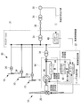
- FIG. 2 is a schematic diagram showing the overall configuration of the wind farm 30 and the electrical configuration of the wind power generator 10 according to the first embodiment.
- the wind farm 30 includes a plurality of wind turbine generators 10, sub stations 31, and a plurality of wind turbine controllers 32 provided corresponding to the respective wind turbine generators 10.
- the combination of the wind power generator 10 and the windmill controller 32 is called a wind power generation system.
- Each wind power generation apparatus 10 is connected to the substation 31 via the transformer 34 and is connected to the grid via the transformer 34 and the power transmission line 36 included in the substation 31 to supply power to the power system 38. .
- the substation 31 is provided with a master controller 41 (for example, SCADA (Supervisory Control And Data Acquisition)) that controls the entire wind farm 30.
- SCADA Supervisory Control And Data Acquisition
- the master controller 41 receives a system request output value indicating an output value (amount of power) required from the power system 38 and transmits it to each wind turbine control device 32.
- the windmill controller 32 In order to control the corresponding wind turbine generator 10, the windmill controller 32 generates a power command value corresponding to the system required output value, and controls the power generation output (active power) of the corresponding wind turbine generator 10, In order to control the pitch angle of the blade 20, a pitch angle command value is generated and output to a pitch actuator (not shown). Further, the windmill control device 32 transmits data indicating the power generation output of the wind turbine generator 14 and the control state of the wind turbine generator 14 to the master controller 41.
- the windmill control device 32 includes a turbine controller 40 and a converter controller 42.
- the turbine controller 40 stores a set value (hereinafter referred to as “frequency set value”) of the frequency of the power generation output of the wind turbine generator 10 as a parameter corresponding to the system required output value, and based on the frequency set value.
- a power command value is generated and output to the converter controller 42.
- the converter controller 42 controls the converter 44 provided in the wind power generator 10 based on the input power command value.
- the converter 44 controls the power generation output from the generator 46 to the power system 38 based on the control signal from the converter controller 42.
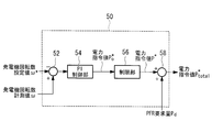
- FIG. 3 is a block diagram showing a configuration of a power command value generation unit 50 that generates a power command value.
- the power command value generation unit 50 receives the generator rotation speed setting value ⁇ * and the generator rotation speed measurement value ⁇ .
- the generator rotation speed setting value ⁇ * is generated based on the frequency setting value, and the generator rotation speed measurement value ⁇ is the rotation speed of the generator 46 actually measured.
- the generator rotational speed set value ⁇ * and the generator rotational speed measured value ⁇ are input to the subtractor 52, and the subtractor 52 calculates a deviation between the generator rotational speed set value ⁇ * and the generator rotational speed measured value ⁇ . , Output to the PI control unit 54.
- the PI control unit 54 generates a power command value P * o based on the input deviation and outputs it to the limiting unit 56.
- Limiting section 56 if the input power command value P * o exceeds the predetermined upper limit value, the electric power control value P * o output is limited to the upper limit. Power command value output from the limit unit 56 P * is added to the PFR demand P d by the adder 58, and output to the converter controller 42 as the power command value P * total.
- PFR demand P d is output from the PFR request amount generating unit 60 described later is provided to the turbine controller 40.
- the wind turbine generator 10 can change the power generation output in accordance with the fluctuation of the frequency of the power system 38 (hereinafter referred to as “system frequency”) under the control of the wind turbine controller 32. That is, when a fluctuation occurs in the system frequency, the wind turbine generator 10 executes PFR that recovers the fluctuation. Then, the PFR demand P d, is an increase amount, also reduces the amount of power output to run the PFR.
- system frequency the frequency of the power system 38
- the wind turbine generator 10 executes PFR that recovers the fluctuation.
- the PFR demand P d is an increase amount, also reduces the amount of power output to run the PFR.
- the PFR demand P d is too large, for example, when the rotation speed of the rotor 18 is small, when used for power generation until the inertia force the rotor 18 has the rotational speed of the rotor 18 is below the disconnecting lower
- the wind power generator 10 may be disconnected.
- the number of rotations of the rotor 18 is large and an increase in the amount of power generation is required, the number of rotations of the rotor 18 may exceed the upper limit of overspeed, and the wind power generator 10 may trip.
- the disconnection and trip of the wind power generation apparatus 10 may not only contribute to the recovery of fluctuations in the frequency of the power system 38, but may make the frequency of the power system 38 more unstable.
- the wind turbine control apparatus 32 According to the first embodiment generates a restricted so as not to excessively PFR demand P d.
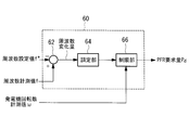
- FIG. 4 is a block diagram showing a configuration of the PFR request amount generation unit 60 according to the first embodiment.
- the PFR request amount generation unit 60 includes a subtractor 62, an adjustment unit 64, and a restriction unit 66.
- the subtractor 62 receives a frequency measurement value (hereinafter referred to as “frequency measurement value”) f of the power generation output of the wind power generation apparatus 10 and a frequency set value f * of the wind power generation apparatus 10, and the frequency measurement value f A frequency change amount that is a difference from the frequency set value f * is calculated.
- frequency measurement value hereinafter referred to as “frequency measurement value”
- the frequency change amount is a difference between the frequency of the power generation output (frequency set value f * ) for which the wind power generator 10 is required and the frequency of the actual power generation output (frequency measurement value f).
- the frequency setting value f * for recovering the fluctuation is input to the PFR request amount generation unit 60. That is, when a frequency variation occurs in the power system 38, the subtractor 62 calculates a frequency change amount required to recover the frequency variation of the power system 38.
- the adjustment unit 64 calculates a power change amount corresponding to the frequency change amount by multiplying the frequency change amount by a predetermined adjustment rate (1 / R (1 / R), R is a constant).
- the limiter 66 receives a measurement value (hereinafter referred to as “generator rotation speed measurement value”) ⁇ of the generator 46, and the input power change amount becomes the generator rotation speed measurement value ⁇ .
- the PFR request amount P d restricted based on the output is output to the power command value generation unit 50.
- the frequency and power (active power) of the power generation output of the wind turbine generator 10 are calculated so that the power corresponding to the frequency is calculated by multiplying the frequency change amount by the adjustment rate by the adjustment unit 64. Have a one-to-one relationship, and changing the frequency changes the power.
- the rotational speed of the generator 46 has a relationship with the rotational speed of the rotor 18. When the rotational speed of the generator 46 is low, the rotational speed of the rotor 18 is low, and when the rotational speed of the generator 46 is high, the rotor 18. The number of revolutions is also high.
- the wind turbine control device 32 limits the power change amount according to the frequency change amount based on the generator rotation speed measurement value ⁇ related to the rotation speed of the rotor 18.
- the increase or decrease of the power generation output is prevented, and the wind power generator 10 is prevented from being unable to supply power to the power system 38.
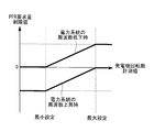
- the limiting unit 66 is based on the relationship between the generator rotational speed ⁇ and the PFR request amount limit value illustrated in FIG. 4, and the PFR request amount P d that limits the input power change amount. Is output.
- the limiting unit 66 sets the power change amount as the first limit value, and the generator rotational speed measured value ⁇ is equal to or greater than the maximum set value.
- the power change amount is set to a predetermined second limit value that is larger than the first limit value.
- the limiting unit 66 sets the power change amount limit value as the first limit value as the generator rotational speed measured value ⁇ increases. To a second limit value.
- the generator rotation speed measurement value ⁇ is equal to or less than the minimum set value.
- the rotational speed of the rotor 18 is lower, and if the inertial force of the rotor 18 is used to output more power than the current state, the subsequent rotational speed of the rotor 18 becomes too low, and the wind power generator 10 generates power.
- a first limit value (0 (zero) in the example of FIG. 5) is provided for the power change amount to prevent the wind power generator 10 from being disconnected.
- PFR demand P d of generator speed measurement value ⁇ wind turbine generator below the minimum set value is 10, since the 0, the wind power generation device 10 does not execute the PFR.
- the case where the measured generator rotational speed value ⁇ is equal to or larger than the maximum set value is the case where the rotational speed of the rotor 18 is higher, and output more power than the current state. Then, it is a case where the wind power generator 10 may trip. In such a case, a second limit value is provided for the amount of change in power to prevent the wind power generator 10 from tripping.
- the limit value of the power change amount is increased with the increase in the rotational speed of the generator 46, thereby generating the generator 46. limits the power variation in the limit value corresponding to the rotational speed, is output as the PFR demand P d.
- PFR demand P d is supplied from 0 because changes in the range of positive values, the wind turbine generator 10, the more power to the power grid 38.
- the windmill control device 32 changes the pitch angle of the blades 20 to the finer side, increases the rotation speed of the rotor 18 to increase the power generation output, and the inertial force stored in the rotor 18. Used to control the power generation output to increase.
- the wind turbine generator 10 reduces the power supplied to the power grid 38.
- the windmill control device 32 performs control to change the pitch angle of the blades 20 to the feather side and decrease the rotational speed of the rotor 18 to reduce the power generation output.
- the wind turbine control device 32 has an excessive increase / decrease in the power generation output when the frequency fluctuation of the power system 38 is recovered, and the wind power generation device 10 cannot supply power to the power system. Can be more reliably prevented.
- PFR request amount limit value shown in FIG. 5 is an example, and the present invention is not limited to this.
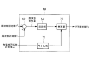
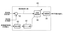
- FIG. 6 shows a configuration of the PFR request amount generation unit 60 according to the second embodiment. 6 that are the same as those in FIG. 4 are assigned the same reference numerals as in FIG. 4 and descriptions thereof are omitted.
- the PFR request amount generation unit 60 according to the second embodiment includes a gain unit 70 and a multiplier 72.
- the gain unit 70 receives the generator rotational speed measurement value ⁇ and outputs a gain based on the generator rotational speed measurement value ⁇ to the multiplier 72.
- the gain output from the gain unit 70 is a variable gain that changes based on the generator rotational speed measurement value ⁇ , and is set to the first gain when the generator rotational speed measurement value ⁇ is less than or equal to the minimum set value.
- the second gain is set. That is, the power change amount is reduced by setting the first gain and the second gain small. This prevents the rotational speed of the rotor 18 from becoming too low and the power generation output from becoming too high.
- the gain is higher than the first gain and the second gain with the increase of the generator rotational speed measurement value ⁇ .
- the gain is set so as to increase to a gain and decrease to the second gain when the third gain is reached.
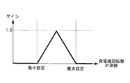
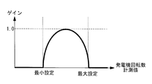
- FIG. 7A and 7B are schematic diagrams illustrating an example of a variable gain according to the second embodiment.
- FIG. 7A illustrates a case where the gain changes in a triangular shape
- FIG. 7B illustrates that the gain changes in an arc shape.
- the values of the first gain, the second gain, and the third gain are not limited to this, and may be other values, and the values of the first gain and the second gain may be different.
- the gain change is not limited to a triangular shape or an arc shape, and may be a discontinuous change that changes stepwise according to a measured value of the generator rotational speed, for example, instead of a continuous change.
- the multiplier 72 is supplied with the gain outputted from the power variation and a gain unit 70 to be output from the Chojo unit 64 multiplies the power change amount and the gain, the result of multiplying by the PFR demand P d It outputs to the electric power command value generation unit 50.
- the wind turbine control device 32 changes the gain according to the generator rotation speed measurement value and multiplies the gain by the amount of change in power.
- the wind turbine control device 32 changes the gain according to the generator rotation speed measurement value and multiplies the gain by the amount of change in power.
- the configurations of the wind turbine generator 10, the wind farm 30, and the power command value generation unit 50 according to the third embodiment are the same as those of the wind turbine generator 10 according to the first embodiment shown in FIGS. Since it is the same as that of the structure of the firm 30 and the electric power command value production
- the PFR request amount generation unit 60 corrects the power change amount according to the rotation acceleration of the generator 46. For example, when the generator 46 decelerates significantly (to prevent a decrease in the rotational speed), the power change amount is corrected to reduce the PFR request amount, and when the generator 46 accelerates greatly, the power change amount is corrected. Thus, the PFR request amount is increased.
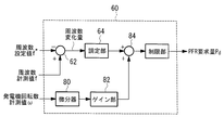
- FIG. 8A and 8B show the configuration of the PFR request amount generation unit 60 according to the third embodiment.
- FIG. 8A and FIG. 8B the same components as those in FIG. 4 are denoted by the same reference numerals as those in FIG.
- the configuration of the PFR request amount generation unit 60 illustrated in FIG. 8A is a case where the power change amount is corrected by adding a gain corresponding to the generator rotation speed measurement value to the power change amount.
- the PFR request amount generation unit 60 illustrated in FIG. 8A includes a differentiator 80, a gain unit 82, an adder 84, and a limiting unit 86.
- the differentiator 80 receives the generator rotation speed measurement value ⁇ , differentiates the generator rotation speed measurement value ⁇ , calculates the rotation acceleration of the generator 46, and outputs the acceleration to the gain unit 82.
- the PFR required amount generation unit 60 according to the third embodiment is similar to the function of the differentiator 80 in order to avoid the influence of noise instead of the differentiator 80 (generator It is also possible to use a filter having a characteristic of high gain in the high frequency band that emphasizes a quick change of 46 rotations.
- the gain unit 82 outputs a gain corresponding to the acceleration and outputs the gain to the adder 84.
- the adder 84 receives the power change amount output from the adjustment unit 64 and the gain output from the gain unit 82, adds the power change amount with the gain, and outputs the result to the limiting unit 86.
- the limiting unit 86 is set with a lower limit value and an upper limit value, and outputs a PFR request amount P d that is limited so that the result output from the adder 84 falls within the range between the lower limit value and the upper limit value.
- the PFR request amount generation unit 60 according to the third embodiment may use the restriction unit 66 included in the PFR request amount generation unit 60 according to the first embodiment as the restriction unit 86.
- the configuration of the PFR request amount generation unit 60 illustrated in FIG. 8B is a case where the power change amount is corrected by making the arbitration rate variable.
- the PFR request amount generation unit 60 illustrated in FIG. 8B includes a modulatable constant unit 88.
- the modulatable constant unit 88 receives the frequency change amount output from the subtractor 62 and the gain output from the gain unit 82. Then, the modulatable constant unit 88 changes the settling rate according to the input gain, calculates the voltage change amount by multiplying the changed arbitration rate and the frequency change amount, and limits the voltage change amount. To the unit 86. When the input gain (differential value of the rotational speed of the generator 46) is large, the tunable constant section 88 reduces the adjustment rate and rotates the rotor 18 due to excessive inertia force.
- the wind turbine control device 32 corrects the amount of power change according to the acceleration of the rotation of the generator 46. Therefore, when the fluctuation of the frequency of the power system 38 is recovered, the power generation output Therefore, it is possible to more reliably prevent the wind power generation apparatus 10 from supplying power to the power system.
- the PFR request amount generation unit 60 predicts fluctuations in the power generation output frequency and wind speed of the wind turbine generator 10 and corrects the power change amount according to the prediction result. For example, when the frequency and wind speed of the power generation output of the generator 46 are small (in order to prevent a decrease in the rotational speed of the rotor), the power change amount is corrected to reduce the PFR request amount, and the power generation output of the generator 46 is reduced. When the frequency and wind speed increase, the power change amount is corrected to increase the PFR request amount.
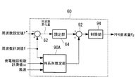
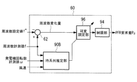
- 9A and 9B show a configuration of the PFR request amount generation unit 60 according to the fourth embodiment.
- 9A and 9B that are the same as in FIG. 4 are assigned the same reference numerals as in FIG. 4, and descriptions thereof are omitted.
- the configuration of the PFR request amount generation unit 60 illustrated in FIG. 9A is a case where the power change amount is corrected by adding a value corresponding to the frequency of the power generation output or the wind speed to the power change amount.
- the PFR request amount generation unit 60 illustrated in FIG. 9A includes a time series estimation unit 90A, an adder 92, and a restriction unit 94.
- the time series estimation unit 90A uses a time series estimation algorithm that uses a statistical technique such as an autoregressive model based on the generator rotational speed measurement value ⁇ , the frequency measurement value f, and the wind speed for the wind power generator 10 to generate wind power.
- the frequency of the power generation output of the device 10 and the fluctuation amount of the wind speed with respect to the wind power generation device 10 are predicted, a correction output is obtained from the prediction result, and the correction output is output to the adder 92.
- the adder 92 receives the power change amount output from the adjustment unit 64 and the correction output output from the time-series estimation unit 90A, adds the power change amount with the correction value, and outputs the result to the restriction unit 94. To do.
- the limiting unit 94 is set with a lower limit value and an upper limit value, and outputs a PFR request amount P d that is limited so that the result output from the adder 92 falls within the range of the lower limit value and the upper limit value.
- the PFR request amount generation unit 60 according to the fourth embodiment may use the restriction unit 66 included in the PFR request amount generation unit 60 according to the first embodiment as the restriction unit 94.
- the configuration of the PFR request amount generation unit 60 illustrated in FIG. 9B is a case where the power change amount is corrected by making the arbitration rate variable.
- the PFR request amount generation unit 60 illustrated in FIG. 9B includes a time series estimation unit 90B and a modulatable constant unit 64B.
- the time series estimation unit 90B uses a time series estimation algorithm using a statistical technique such as an autoregressive model based on the generator rotational speed measurement value ⁇ , the frequency measurement value f, and the wind speed with respect to the wind power generator 10 to generate wind power.
- the frequency of the power generation output of the apparatus 10 and the fluctuation amount of the wind speed with respect to the wind power generation apparatus 10 are predicted, a correction coefficient is obtained from the prediction result, and the correction coefficient is output to the adder 92.
- the modifiable constant unit 64B receives the frequency change amount output from the subtractor 62 and the correction coefficient output from the time series estimation unit 90B. Then, the modulatable constant unit 64B changes the settling rate by multiplying the settling rate by the input correction coefficient, and further calculates the voltage change amount by further multiplying the changed arbitration rate and the frequency change amount. The voltage change amount is output to the limiting unit 94.
- the wind turbine control device 32 corrects the amount of power change according to the acceleration of the rotation of the generator 46. Therefore, when the fluctuation of the frequency of the power system 38 is recovered, the power generation output Therefore, it is possible to more reliably prevent the wind power generation apparatus 10 from supplying power to the power system.
- the values input to the time series estimation units 90A and 90B are not limited to the frequency measurement value f, the generator rotation speed measurement value ⁇ , and the wind speed, but other values are input and used for the time series estimation algorithm. Also good.
- the present invention is not limited to this, and the wind farm 30 includes one wind power generator 10. It is good also as a form provided.
Landscapes
- Engineering & Computer Science (AREA)
- Life Sciences & Earth Sciences (AREA)
- Sustainable Development (AREA)
- Sustainable Energy (AREA)
- Chemical & Material Sciences (AREA)
- Combustion & Propulsion (AREA)
- Mechanical Engineering (AREA)
- General Engineering & Computer Science (AREA)
- Power Engineering (AREA)
- Wind Motors (AREA)
- Control Of Eletrric Generators (AREA)
Abstract
Description
特許文献1には、PFRにおいて、ロータの回転数や発電出力に基づいて、出力する有効電力に制限を設けることが記載されている。
このような、PFRの実行中の風力発電装置の解列やトリップは、電力系統に対して擾乱として作用し、PFRを行わない場合よりも電力系統の周波数をより不安定にする可能性がある。また、一旦トリップすると再起動までに時間を要するため、風力発電装置は、電力系統の周波数を回復させるという目的を達成できない。
制限手段によって、算出手段で算出された周波数変化量に応じた電力変化量が、発電機の回転数に基づいて制限される。
以下、本発明の第1実施形態について説明する。
図1は、本第1実施形態に係る風力発電装置10の外観図である。
図1に示す風力発電装置10は、所謂可変速風車であり、基礎12上に立設される支柱14と、支柱14の上端に設置されるナセル16と、略水平な軸線周りに回転可能にしてナセル16に設けられるロータ18とを有している。
タービンコントローラ40は、系統要求出力値に応じたパラメータとして、風力発電装置10の発電出力の周波数の設定値(以下、「周波数設定値」という。)を記憶しており、該周波数設定値に基づいて、電力指令値を生成し、コンバータコントローラ42へ出力する。
そして、コンバータコントローラ42は、入力された電力指令値に基づいて、風力発電装置10に備えられたコンバータ44を制御する。
コンバータ44は、コンバータコントローラ42からの制御信号に基づいて、発電機46から電力系統38への発電出力を制御する。
図3は、電力指令値を生成する電力指令値生成部50の構成を示すブロック図である。
減算器62は、風力発電装置10の発電出力の周波数の計測値(以下、「周波数計測値」という。)fと、風力発電装置10の周波数設定値f*が入力され、周波数計測値fと周波数設定値f*との差である周波数変化量を算出する。
また、発電機46の回転数は、ロータ18の回転数と関係性を有し、発電機46の回転数が低いとロータ18の回転数も低く、発電機46の回転数が高いとロータ18の回転数も高い。
一方、電力系統38の周波数低下時において、発電機回転数計測値ωが最大設定値以上の場合とは、ロータ18の回転数がより高い場合であり、現状よりも多くの電力を出力させようとすると、風力発電装置10がトリップする可能性がある場合である。このような場合に、電力変化量に第2制限値を設け、風力発電装置10のトリップを防止する。
このように、電力系統38の周波数低下時では、PFR要求量Pdは、0から正の値の範囲で変化するので、風力発電装置10は、より多くの電力を電力系統38へ供給する。具体的には、風車制御装置32は、翼20のピッチ角をよりファイン側へ変更し、ロータ18の回転数を上昇させて発電出力を増加させる制御、ロータ18に蓄えられている慣性力を用いて発電出力を上昇させる制御等を行う。
このため、電力系統38の周波数上昇時では、PFR要求量Pdは、負の値から0の範囲で変化するので、風力発電装置10は、電力系統38へ供給する電力を減少させる。具体的には、風車制御装置32は、翼20のピッチ角をよりフェザー側へ変更し、ロータ18の回転数を下降させて発電出力を減少させる制御等を行う。
以下、本発明の第2実施形態について説明する。
なお、本第2実施形態に係る風力発電装置10、ウインドファーム30、及び電力指令値生成部50の構成は、図1,2,3に示される第1実施形態に係る風力発電装置10、ウインドファーム30、及び電力指令値生成部50の構成と同様であるので説明を省略する。
本第2実施形態に係るPFR要求量生成部60は、ゲイン部70及び乗算器72を備える。
ゲイン部70から出力されるゲインは、発電機回転数計測値ωに基づいて変化する可変ゲインであり、発電機回転数計測値ωが最小設定値以下の場合、第1ゲインに設定され、発電機回転数計測値ωが第2設定値以上の場合、第2ゲインに設定される。すなわち、第1ゲイン及び第2ゲインを小さく設定することで、電力変化量は、小さくされる。これにより、ロータ18の回転数が低くなりすぎること及び発電出力が高くなりすぎることが防がれる。
一方、発電機回転数計測値ωが第1設定値と第2設定値との間の場合、ゲインは、発電機回転数計測値ωの上昇と共に第1ゲイン及び第2ゲインよりも高い第3ゲインまで上昇し、該第3ゲインに達すると、第2ゲインに下降するように設定される。
一方、電力系統38の周波数上昇時(周波数設定値f*が周波数計測値fよりも小さくなる場合)では、調定部64から出力される電力変化量は、負の値であるため、乗算器72から出力されるPFR要求量Pdは、負の値から0の範囲で変化するので、風力発電装置10は、電力系統38へ供給する電力を減少させる。
以下、本発明の第3実施形態について説明する。
図8Aに示すPFR要求量生成部60は、微分器80、ゲイン部82、加算器84、及び制限部86を備える。
なお、本第3実施形態に係るPFR要求量生成部60は、微分器80の代わりに、ノイズの影響を受けないようにするため、微分器80の機能に類似、近似的な特性(発電機46の回転の素早い変化を強調するような、高周波帯域のゲインが高い特性)を有するフィルタを用いてもよい。
図8Bに示すPFR要求量生成部60は、可変調定部88を備えている。
なお、可変調定部88は、入力されるゲイン(発電機46の回転数の微分値)が大きい場合には、調定率を小さくして、慣性力の取りすぎに起因してロータ18の回転数が大きく変化する(落ち込む)ことを回避する一方、入力されるゲインが小さい場合には、慣性力を多めに取り出しても風力発電装置10が解列に至るまでロータ18の回転数が落ち込むことはないと考えられるため、調定率を大きくして、より多くの電力を風力発電装置10から電力系統38へ供給する。
以下、本発明の第4実施形態について説明する。
なお、本第4実施形態に係る風力発電装置10、ウインドファーム30、及び電力指令値生成部50の構成は、図1,2,3に示される第1実施形態に係る風力発電装置10、ウインドファーム30、及び電力指令値生成部50の構成と同様であるので説明を省略する。
図9Aに示すPFR要求量生成部60は、時系列推定部90A、加算器92、及び制限部94を備える。
図9Bに示すPFR要求量生成部60は、時系列推定部90B、可変調定部64Bを備えている。
また、時系列推定部90A,90Bに入力される値は、周波数計測値f、発電機回転数計測値ω、及び風速に限らず、他の値が入力され、時系列推定アルゴリズムに用いられてもよい。
18 ロータ
20 翼
30 ウインドファーム
32 風車制御装置
38 電力系統
46 発電機
62 減算器
66 制限部
70 ゲイン部
80 微分器
82 ゲイン部
90A 時系列推定部
90B 時系列推定部
Claims (7)
- 複数枚の翼を有するロータが風を受けて回転し、該ロータの回転により発電機が発電し、電力系統に電力を供給すると共に、該電力系統の周波数の変動に応じて電力系統へ供給する電力量が変更可能な風力発電装置の制御装置であって、
前記風力発電装置の発電出力の周波数の計測値と、該風力発電装置の発電出力の周波数の設定値との差である周波数変化量を算出する算出手段と、
前記算出手段によって算出された前記周波数変化量に応じた電力変化量を、前記発電機の回転数に基づいて制限する制限手段と、
を備えた風力発電装置の制御装置。 - 前記制限手段は、前記発電機の回転数が第1設定値以下の場合に、前記電力変化量を予め定められた第1制限値とし、前記発電機の回転数が第2設定値以上の場合に、前記電力変化量を前記第1制限値よりも大きい予め定められた第2制限値とし、前記発電機の回転数が第1設定値を超え第2設定値未満の場合に、前記発電機の回転数の上昇と共に前記電力変化量の制限値を前記第1制限値から前記第2制限値の間で上昇させる請求項1記載の風力発電装置の制御装置。
- 前記制限手段は、前記電力変化量に所定のゲインを乗算し、
前記所定のゲインは、前記発電機の回転数が第1設定値以下の場合、第1ゲインであり、前記発電機の回転数が第2設定値以上の場合、第2ゲインであり、前記発電機の回転数が前記第1設定値を超えると、前記発電機の回転数の上昇と共に前記第1ゲイン及び前記第2ゲインよりも高い第3ゲインまで上昇し、該第3ゲインに達すると、前記第2設定値に達するまで前記第2ゲインに下降する請求項1記載の風力発電装置の制御装置。 - 前記制限手段は、前記発電機の回転の加速度に基づいて、前記電力変化量を補正する請求項1記載の風力発電装置の制御装置。
- 前記制限手段は、前記発電機の回転数、前記周波数の計測値、及び前記風力発電装置に対する風速に基づいて、前記風力発電装置の発電出力の周波数、前記風力発電装置に対する風速の変動量を予測し、予測結果に基づいて前記電力変化量を補正する請求項1記載の風力発電装置の制御装置。
- 複数枚の翼を有するロータが風を受けて回転し、該ロータの回転により発電機が発電し、電力系統に電力を供給すると共に、該電力系統の周波数の変動に応じて電力系統へ供給する電力量が変更可能な風力発電装置と、
前記風力発電装置を制御する請求項1から請求項5の何れか1項に記載の風力発電装置の制御装置と、
を備えた風力発電システム。 - 複数枚の翼を有するロータが風を受けて回転し、該ロータの回転により発電機が発電し、電力系統に電力を供給すると共に、該電力系統の周波数の変動に応じて電力系統へ供給する電力量が変更可能な風力発電装置の制御方法であって、
前記風力発電装置の発電出力の周波数の計測値と、該風力発電装置の発電出力の周波数の設定値との差である周波数変化量を算出する第1工程と、
前記第1工程によって算出された前記周波数変化量に応じた電力変化量を、前記発電機の回転数に基づいて制限する第2工程と、
を含んだ風力発電装置の制御方法。
Priority Applications (4)
| Application Number | Priority Date | Filing Date | Title |
|---|---|---|---|
| CN201180034622.0A CN103052794B (zh) | 2010-12-28 | 2011-12-28 | 风力发电装置的控制装置、风力发电系统及风力发电装置的控制方法 |
| EP11853529.3A EP2660464B1 (en) | 2010-12-28 | 2011-12-28 | Control device for wind power generation device, wind power generation system, and control method for wind power generation device |
| KR1020137000762A KR20130053442A (ko) | 2010-12-28 | 2011-12-28 | 풍력 발전 장치의 제어 장치, 풍력 발전 시스템, 및 풍력 발전 장치의 제어 방법 |
| US13/454,666 US9341163B2 (en) | 2010-12-28 | 2012-04-24 | Wind-turbine-generator control apparatus, wind turbine generator system, and wind-turbine-generator control method |
Applications Claiming Priority (2)
| Application Number | Priority Date | Filing Date | Title |
|---|---|---|---|
| JP2010294142A JP5455890B2 (ja) | 2010-12-28 | 2010-12-28 | 風力発電装置の制御装置、風力発電システム、及び風力発電装置の制御方法 |
| JP2010-294142 | 2010-12-28 |
Related Child Applications (1)
| Application Number | Title | Priority Date | Filing Date |
|---|---|---|---|
| US13/454,666 Continuation US9341163B2 (en) | 2010-12-28 | 2012-04-24 | Wind-turbine-generator control apparatus, wind turbine generator system, and wind-turbine-generator control method |
Publications (1)
| Publication Number | Publication Date |
|---|---|
| WO2012091102A1 true WO2012091102A1 (ja) | 2012-07-05 |
Family
ID=46383190
Family Applications (1)
| Application Number | Title | Priority Date | Filing Date |
|---|---|---|---|
| PCT/JP2011/080421 Ceased WO2012091102A1 (ja) | 2010-12-28 | 2011-12-28 | 風力発電装置の制御装置、風力発電システム、及び風力発電装置の制御方法 |
Country Status (5)
| Country | Link |
|---|---|
| EP (1) | EP2660464B1 (ja) |
| JP (1) | JP5455890B2 (ja) |
| KR (1) | KR20130053442A (ja) |
| CN (1) | CN103052794B (ja) |
| WO (1) | WO2012091102A1 (ja) |
Cited By (4)
| Publication number | Priority date | Publication date | Assignee | Title |
|---|---|---|---|---|
| KR101383792B1 (ko) | 2013-01-02 | 2014-04-10 | 한국에너지기술연구원 | 라이다 측정을 이용한 나셀 풍속계 보정 방법 |
| WO2019066139A1 (ko) * | 2017-09-27 | 2019-04-04 | 제주대학교 산학협력단 | 지상 기반 라이다, 라이다 측정오차 보정 장치 및 방법 |
| US20210296883A1 (en) * | 2020-03-19 | 2021-09-23 | Fuji Electric Co., Ltd. | Grid connected inverter, and method for reducing grid frequency variation |
| CN114216669A (zh) * | 2021-12-17 | 2022-03-22 | 大连民族大学 | 一种可实现激励频率慢变的试验设备及其试验方法 |
Families Citing this family (4)
| Publication number | Priority date | Publication date | Assignee | Title |
|---|---|---|---|---|
| DE102013207255A1 (de) | 2013-04-22 | 2014-10-23 | Wobben Properties Gmbh | Verfahren zum Einspeisen elektrischer Leistung in ein elektrisches Versorgungsnetz |
| CN105281621B (zh) * | 2015-10-09 | 2018-09-11 | 南京南瑞继保电气有限公司 | 静止变频器功率控制方法 |
| EP3512062A1 (en) * | 2018-01-11 | 2019-07-17 | Ørsted Wind Power A/S | An offshore wind farm and substation |
| CN113217281B (zh) * | 2021-05-11 | 2022-12-09 | 上海电气风电集团股份有限公司 | 风力发电系统及其控制方法、装置、电子设备、存储介质 |
Citations (4)
| Publication number | Priority date | Publication date | Assignee | Title |
|---|---|---|---|---|
| JP2004015854A (ja) * | 2002-06-04 | 2004-01-15 | Mitsubishi Electric Corp | 可変速発電電動機システム |
| WO2004047284A1 (ja) * | 2002-11-15 | 2004-06-03 | Zephyr Corporation | 風力発電装置 |
| JP2005073418A (ja) * | 2003-08-26 | 2005-03-17 | Ishikawajima Harima Heavy Ind Co Ltd | 風力発電装置 |
| JP2007231778A (ja) * | 2006-02-28 | 2007-09-13 | Mitsubishi Heavy Ind Ltd | 風力発電システム、及びその制御方法 |
Family Cites Families (9)
| Publication number | Priority date | Publication date | Assignee | Title |
|---|---|---|---|---|
| KR100642554B1 (ko) * | 2001-04-20 | 2006-11-03 | 알로이즈 우벤 | 풍력 발전 플랜트의 운전 방법 |
| DK1467463T3 (en) * | 2003-04-09 | 2017-03-27 | Gen Electric | Wind farm and method for operating it |
| US7345373B2 (en) * | 2005-11-29 | 2008-03-18 | General Electric Company | System and method for utility and wind turbine control |
| US7352075B2 (en) * | 2006-03-06 | 2008-04-01 | General Electric Company | Methods and apparatus for controlling rotational speed of a rotor |
| CN102067407B (zh) * | 2008-06-30 | 2014-06-18 | 维斯塔斯风力系统集团公司 | 控制包括多个风力涡轮发电机的风力发电站的方法和系统 |
| BRPI0822536A2 (pt) * | 2008-10-16 | 2015-06-23 | Mitsubishi Heavy Ind Ltd | Sistema de gerador de turbina eólica, e, método para controlar o mesmo |
| US8093739B2 (en) * | 2009-01-09 | 2012-01-10 | General Electric Company | System and method for fixed frequency power generation |
| JP5550283B2 (ja) * | 2009-08-06 | 2014-07-16 | 三菱重工業株式会社 | 風力発電装置、風力発電装置の制御方法、風力発電システム及び風力発電システムの制御方法 |
| DE102009037238B3 (de) * | 2009-08-12 | 2010-12-09 | Repower Systems Ag | Windenergieanlage mit veränderbarer Drehzahlkennlinie |
-
2010
- 2010-12-28 JP JP2010294142A patent/JP5455890B2/ja active Active
-
2011
- 2011-12-28 EP EP11853529.3A patent/EP2660464B1/en active Active
- 2011-12-28 CN CN201180034622.0A patent/CN103052794B/zh active Active
- 2011-12-28 KR KR1020137000762A patent/KR20130053442A/ko not_active Ceased
- 2011-12-28 WO PCT/JP2011/080421 patent/WO2012091102A1/ja not_active Ceased
Patent Citations (4)
| Publication number | Priority date | Publication date | Assignee | Title |
|---|---|---|---|---|
| JP2004015854A (ja) * | 2002-06-04 | 2004-01-15 | Mitsubishi Electric Corp | 可変速発電電動機システム |
| WO2004047284A1 (ja) * | 2002-11-15 | 2004-06-03 | Zephyr Corporation | 風力発電装置 |
| JP2005073418A (ja) * | 2003-08-26 | 2005-03-17 | Ishikawajima Harima Heavy Ind Co Ltd | 風力発電装置 |
| JP2007231778A (ja) * | 2006-02-28 | 2007-09-13 | Mitsubishi Heavy Ind Ltd | 風力発電システム、及びその制御方法 |
Cited By (6)
| Publication number | Priority date | Publication date | Assignee | Title |
|---|---|---|---|---|
| KR101383792B1 (ko) | 2013-01-02 | 2014-04-10 | 한국에너지기술연구원 | 라이다 측정을 이용한 나셀 풍속계 보정 방법 |
| WO2019066139A1 (ko) * | 2017-09-27 | 2019-04-04 | 제주대학교 산학협력단 | 지상 기반 라이다, 라이다 측정오차 보정 장치 및 방법 |
| US20210296883A1 (en) * | 2020-03-19 | 2021-09-23 | Fuji Electric Co., Ltd. | Grid connected inverter, and method for reducing grid frequency variation |
| US11658478B2 (en) * | 2020-03-19 | 2023-05-23 | Fuji Electric Co., Ltd. | Grid connected inverter, and method for reducing grid frequency variation |
| CN114216669A (zh) * | 2021-12-17 | 2022-03-22 | 大连民族大学 | 一种可实现激励频率慢变的试验设备及其试验方法 |
| CN114216669B (zh) * | 2021-12-17 | 2024-05-28 | 大连民族大学 | 一种可实现激励频率慢变的试验设备及其试验方法 |
Also Published As
| Publication number | Publication date |
|---|---|
| KR20130053442A (ko) | 2013-05-23 |
| JP2012140902A (ja) | 2012-07-26 |
| JP5455890B2 (ja) | 2014-03-26 |
| EP2660464A4 (en) | 2015-11-25 |
| EP2660464B1 (en) | 2017-07-26 |
| EP2660464A1 (en) | 2013-11-06 |
| CN103052794A (zh) | 2013-04-17 |
| CN103052794B (zh) | 2015-11-25 |
Similar Documents
| Publication | Publication Date | Title |
|---|---|---|
| US9341163B2 (en) | Wind-turbine-generator control apparatus, wind turbine generator system, and wind-turbine-generator control method | |
| JP5455890B2 (ja) | 風力発電装置の制御装置、風力発電システム、及び風力発電装置の制御方法 | |
| EP2921699B1 (en) | Method for operating a wind farm and wind farm | |
| EP2085611B1 (en) | Power generation stabilization control systems and methods | |
| EP3500751B1 (en) | Dynamic controlled wind turbine shutdown | |
| CN107709762B (zh) | 风力涡轮机的控制方法以及系统 | |
| JP5237454B2 (ja) | 風力発電装置およびその制御方法 | |
| JP5216167B1 (ja) | 風車の出力制御装置及び出力制御方法 | |
| CN107453410B (zh) | 负荷扰动的双馈风机参与风柴微网调频控制方法 | |
| EP2522853B1 (en) | Wind turbine torque-speed control | |
| EP3404258A1 (en) | Power generation stablization control systems and methods | |
| Muljadi et al. | Fixed-speed and variable-slip wind turbines providing spinning reserves to the grid | |
| JP6756489B2 (ja) | 風力発電装置の制御方法 | |
| CN110374807A (zh) | 风力发电机组软停机控制方法及风力发电机组 | |
| CN111396247B (zh) | 考虑载荷和转速约束的电压源型风电机组控制方法及系统 | |
| CN107580660A (zh) | 用于运行风能设备的方法 | |
| WO2013058106A1 (ja) | 風力発電装置及びその方法並びにプログラム | |
| KR101304916B1 (ko) | 풍력 발전기의 블레이드의 피치 제어 방법 | |
| CN108512255A (zh) | 电压跌落故障下dfig动态响应特性分析方法 | |
| CN115370529A (zh) | 用于控制风能设施的方法、风能设施和风电场 | |
| Ramtharan et al. | Support for Spinning Reserve from DFIG based wind turbines | |
| JP2023008840A (ja) | 風力タービンの制御 | |
| Van de Vyver et al. | Energy yield losses due to emulated inertial response with wind turbines | |
| El Itani et al. | Assessment of inertial potential of variable-speed wind turbines | |
| Yan et al. | Improved Rotor Speed Strategy of a DFIG for Suppressing Second Frequency Drop |
Legal Events
| Date | Code | Title | Description |
|---|---|---|---|
| WWE | Wipo information: entry into national phase |
Ref document number: 201180034622.0 Country of ref document: CN |
|
| 121 | Ep: the epo has been informed by wipo that ep was designated in this application |
Ref document number: 11853529 Country of ref document: EP Kind code of ref document: A1 |
|
| ENP | Entry into the national phase |
Ref document number: 20137000762 Country of ref document: KR Kind code of ref document: A |
|
| REEP | Request for entry into the european phase |
Ref document number: 2011853529 Country of ref document: EP |
|
| WWE | Wipo information: entry into national phase |
Ref document number: 2011853529 Country of ref document: EP |
|
| NENP | Non-entry into the national phase |
Ref country code: DE |