WO2012093501A1 - Ressort pneumatique - Google Patents
Ressort pneumatique Download PDFInfo
- Publication number
- WO2012093501A1 WO2012093501A1 PCT/JP2011/057613 JP2011057613W WO2012093501A1 WO 2012093501 A1 WO2012093501 A1 WO 2012093501A1 JP 2011057613 W JP2011057613 W JP 2011057613W WO 2012093501 A1 WO2012093501 A1 WO 2012093501A1
- Authority
- WO
- WIPO (PCT)
- Prior art keywords
- movable body
- stopper
- air spring
- holding body
- holding
- Prior art date
- Legal status (The legal status is an assumption and is not a legal conclusion. Google has not performed a legal analysis and makes no representation as to the accuracy of the status listed.)
- Ceased
Links
Images



Classifications
-
- B—PERFORMING OPERATIONS; TRANSPORTING
- B61—RAILWAYS
- B61F—RAIL VEHICLE SUSPENSIONS, e.g. UNDERFRAMES, BOGIES OR ARRANGEMENTS OF WHEEL AXLES; RAIL VEHICLES FOR USE ON TRACKS OF DIFFERENT WIDTH; PREVENTING DERAILING OF RAIL VEHICLES; WHEEL GUARDS, OBSTRUCTION REMOVERS OR THE LIKE FOR RAIL VEHICLES
- B61F5/00—Constructional details of bogies; Connections between bogies and vehicle underframes; Arrangements or devices for adjusting or allowing self-adjustment of wheel axles or bogies when rounding curves
- B61F5/02—Arrangements permitting limited transverse relative movements between vehicle underframe or bolster and bogie; Connections between underframes and bogies
- B61F5/04—Bolster supports or mountings
- B61F5/10—Bolster supports or mountings incorporating fluid springs
-
- B—PERFORMING OPERATIONS; TRANSPORTING
- B60—VEHICLES IN GENERAL
- B60G—VEHICLE SUSPENSION ARRANGEMENTS
- B60G11/00—Resilient suspensions characterised by arrangement, location or kind of springs
- B60G11/26—Resilient suspensions characterised by arrangement, location or kind of springs having fluid springs only, e.g. hydropneumatic springs
- B60G11/27—Resilient suspensions characterised by arrangement, location or kind of springs having fluid springs only, e.g. hydropneumatic springs wherein the fluid is a gas
-
- B—PERFORMING OPERATIONS; TRANSPORTING
- B61—RAILWAYS
- B61F—RAIL VEHICLE SUSPENSIONS, e.g. UNDERFRAMES, BOGIES OR ARRANGEMENTS OF WHEEL AXLES; RAIL VEHICLES FOR USE ON TRACKS OF DIFFERENT WIDTH; PREVENTING DERAILING OF RAIL VEHICLES; WHEEL GUARDS, OBSTRUCTION REMOVERS OR THE LIKE FOR RAIL VEHICLES
- B61F5/00—Constructional details of bogies; Connections between bogies and vehicle underframes; Arrangements or devices for adjusting or allowing self-adjustment of wheel axles or bogies when rounding curves
- B61F5/02—Arrangements permitting limited transverse relative movements between vehicle underframe or bolster and bogie; Connections between underframes and bogies
-
- F—MECHANICAL ENGINEERING; LIGHTING; HEATING; WEAPONS; BLASTING
- F16—ENGINEERING ELEMENTS AND UNITS; GENERAL MEASURES FOR PRODUCING AND MAINTAINING EFFECTIVE FUNCTIONING OF MACHINES OR INSTALLATIONS; THERMAL INSULATION IN GENERAL
- F16F—SPRINGS; SHOCK-ABSORBERS; MEANS FOR DAMPING VIBRATION
- F16F9/00—Springs, vibration-dampers, shock-absorbers, or similarly-constructed movement-dampers using a fluid or the equivalent as damping medium
- F16F9/02—Springs, vibration-dampers, shock-absorbers, or similarly-constructed movement-dampers using a fluid or the equivalent as damping medium using gas only or vacuum
- F16F9/04—Springs, vibration-dampers, shock-absorbers, or similarly-constructed movement-dampers using a fluid or the equivalent as damping medium using gas only or vacuum in a chamber with a flexible wall
- F16F9/05—Springs, vibration-dampers, shock-absorbers, or similarly-constructed movement-dampers using a fluid or the equivalent as damping medium using gas only or vacuum in a chamber with a flexible wall the flexible wall being of the rolling diaphragm type
- F16F9/052—Springs, vibration-dampers, shock-absorbers, or similarly-constructed movement-dampers using a fluid or the equivalent as damping medium using gas only or vacuum in a chamber with a flexible wall the flexible wall being of the rolling diaphragm type characterised by the bumper
-
- B—PERFORMING OPERATIONS; TRANSPORTING
- B60—VEHICLES IN GENERAL
- B60G—VEHICLE SUSPENSION ARRANGEMENTS
- B60G2202/00—Indexing codes relating to the type of spring, damper or actuator
- B60G2202/10—Type of spring
- B60G2202/15—Fluid spring
- B60G2202/152—Pneumatic spring
-
- B—PERFORMING OPERATIONS; TRANSPORTING
- B60—VEHICLES IN GENERAL
- B60G—VEHICLE SUSPENSION ARRANGEMENTS
- B60G2206/00—Indexing codes related to the manufacturing of suspensions: constructional features, the materials used, procedures or tools
- B60G2206/01—Constructional features of suspension elements, e.g. arms, dampers, springs
- B60G2206/40—Constructional features of dampers and/or springs
- B60G2206/42—Springs
- B60G2206/424—Plunger or top retainer construction for bellows or rolling lobe type air springs
-
- F—MECHANICAL ENGINEERING; LIGHTING; HEATING; WEAPONS; BLASTING
- F16—ENGINEERING ELEMENTS AND UNITS; GENERAL MEASURES FOR PRODUCING AND MAINTAINING EFFECTIVE FUNCTIONING OF MACHINES OR INSTALLATIONS; THERMAL INSULATION IN GENERAL
- F16F—SPRINGS; SHOCK-ABSORBERS; MEANS FOR DAMPING VIBRATION
- F16F9/00—Springs, vibration-dampers, shock-absorbers, or similarly-constructed movement-dampers using a fluid or the equivalent as damping medium
- F16F9/02—Springs, vibration-dampers, shock-absorbers, or similarly-constructed movement-dampers using a fluid or the equivalent as damping medium using gas only or vacuum
- F16F9/04—Springs, vibration-dampers, shock-absorbers, or similarly-constructed movement-dampers using a fluid or the equivalent as damping medium using gas only or vacuum in a chamber with a flexible wall
- F16F9/05—Springs, vibration-dampers, shock-absorbers, or similarly-constructed movement-dampers using a fluid or the equivalent as damping medium using gas only or vacuum in a chamber with a flexible wall the flexible wall being of the rolling diaphragm type
Definitions
- the present invention relates to an air spring for, for example, a railway vehicle provided with a stopper for limiting the amount of displacement in the vertical direction.
- a railway vehicle or the like is equipped with an air spring that is interposed between a wheel side and a vehicle body side to suppress vibration (see FIG. 7).
- the air spring is provided with upper and lower stoppers 101 and 102 for restricting the amount of displacement in the vertical direction. For example, the swing width due to rolling of the vehicle body is suppressed to prevent the vehicle body from contacting the peripheral equipment. It has become.
- the height of the air spring can be adjusted by supplying and exhausting air. For example, when the wheel is worn, the air spring is also used as a vehicle height adjusting device for returning the lowered vehicle height.
- Patent Document 1 enables adjustment of the distance between the upper and lower stoppers so that the distance between the upper and lower stoppers can be prevented from widening while adjusting the height of the air spring.
- An air spring is disclosed (see FIG. 8).
- the air spring of Patent Document 1 is provided with an upper stopper member 103 and a lower stopper member 104 on the upper surface plate and the lower surface plate, respectively, and the upper stopper member 103 can be rotated. 106 and raised surfaces 107 and 108 are provided. The air spring rotates the upper stopper member 103 and selects whether the raised surfaces 107 and 108 face each other or the flat surfaces 105 and 106 and the raised surfaces 107 and 108 face each other. Regardless of the height, the distance between the upper and lower stopper members 103, 104 can be set within a predetermined range.
- JP-A-9-89029 (paragraph numbers 0009, 0014, 0015, 0017, FIG. 1)
- Patent Document 1 adjusts the distance between the stoppers by rotating the upper stopper member provided on the upper surface plate.
- the carriage is pulled out of the vehicle body, It is necessary to remove the vehicle body from the air spring.
- the air spring disclosed in Patent Document 1 has a structure for selecting whether the raised surfaces of the upper and lower stopper members are in contact with each other, or the flat surface and the raised surface are in contact with each other.
- the raised surfaces or the flat surface and the raised surface may not come into contact with each other as expected.
- the stopper may not function normally, and the upper and lower raised surfaces may come into contact with each other only at a narrow area at the end portion, and the stopper member may be damaged.
- An object of the present invention is to provide an air spring capable of easily and surely adjusting the distance between the stoppers and preventing the stoppers from being damaged.
- the air spring according to the present invention has an upper member and a lower member fixed to the upper and lower ends of the bellows, and the upper member and the lower member are in contact with each other so that the displacement amount of the upper member.
- a movable body that can be moved up and down to adjust the height of the stopper surface of the lower member, and a holding body that holds the movable body so as to be movable up and down.
- the movable body is rotatable relative to the holding body relative to the center axis, and at least one of the movable body and the holding body has a taper that can slide relative to the other, with respect to the horizontal plane. Inclined in the circumferential direction.
- the movable body and / or the taper of the holding body is rotated by rotating the movable body relative to the holding body.
- the movable body can be moved up and down simply by sliding with respect to the other.
- the movable body and the holding body are provided on the lower member, the height of the stopper surface of the lower member can be adjusted by moving the movable body up and down without removing the vehicle body from the air spring, and the interval between the stoppers can be increased. It can be adjusted easily and reliably.
- the shape of the stopper surface is not particularly limited, but it is preferable to adopt a configuration in which at least one stopper surface of the upper member and the lower member is formed in a planar shape.
- the stopper surfaces are formed in a flat shape without forming both stopper surfaces in an uneven shape, even if a certain amount of horizontal displacement occurs in the air spring, the stopper can be properly operated.
- the stopper interval can be easily and reliably adjusted.
- the flat stopper surface does not change the distance between the stopper and the other stopper for each part, even when the air spring is displaced in the vertical direction, even if there is some horizontal displacement, Both stopper surfaces can be brought into contact with each other with a set amount of vertical displacement.
- the upper and lower stopper surfaces do not come into contact with each other only in a narrow area at the end of the convex portion, as in the case where both stopper surfaces are formed in an uneven shape, by the amount that at least one of the stopper surfaces is formed flat. Therefore, it is possible to reliably bring both stopper surfaces into contact with each other over a wide area and prevent the stopper surfaces from being damaged.
- the movable body is positioned on one horizontal plane of the movable body and the holding body, and the vertical force acting between the movable body and the holding body is efficiently received on the horizontal plane. It is possible to prevent generation of a force that rotates the movable body relative to the holding body by the action of the taper.
- only one taper is formed without providing a horizontal plane, and for example, the stopper surface is positioned at a desired height by restricting the rotation of the movable body relative to the holding body and preventing the movable body from moving up and down. It may be.
- the movable body can be easily rotated relative to the holding body, and the handle is moved to the other by the fixed portion. Therefore, the movable body can be prevented from rotating with respect to the holding body and can be positioned reliably.
- the present invention is an air spring stopper provided on a lower member of an air spring and contacting the upper member of the air spring to limit the amount of displacement of the upper member.
- a movable body that can adjust the height of the movable body and a holding body that holds the movable body so as to be movable up and down, and the movable body is rotatable relative to the holding body around a central axis,
- a stopper for an air spring wherein at least one of the movable body and the holding body is formed with a taper slidable with respect to the other so as to be inclined with respect to the horizontal plane in the circumferential direction of the movable body.
- the air spring stopper having this configuration has the same main portion as the above air spring, and therefore has the same effect as the above air spring.
- the movable body and the holding body are provided on the lower member of the air spring, and at least one of them is tapered, so that the movable body is rotated up and down with respect to the holding body. It is possible to easily adjust the height of the stopper surface without removing the vehicle body from the air spring.
- the distance between the upper and lower stopper surfaces is adjusted to suppress the swing width due to rolling of the vehicle body while adjusting the vehicle body height by supplying and exhausting air to the air spring. it can.
- the interval between the upper and lower stopper surfaces is reliably adjusted, Damage to the stopper can be prevented.
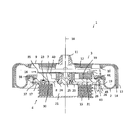
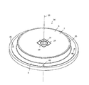
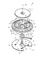
- Sectional view of an air spring according to the present invention Perspective view of the lower stopper as seen from above Perspective view of the lower stopper as seen from below Exploded perspective view of the lower stopper as seen from above Exploded perspective view of the lower stopper viewed from below
- (a-1) to (a-4) are viewed from above
- (b-1) to (b-4) are viewed from below.
- the air spring 1 is interposed between a vehicle body side and a wheel side of a railway vehicle to suppress vibrations, and when a wheel is worn, the air spring 1 supplies and exhausts air.
- an upper member 3 attached to the vehicle body side is fixed to the upper end portion of the bellows 2 made of a cylindrical rubber film, and the lower end portion of the bellows 2 is attached to the wheel side.
- the lower member 4 to be attached is fixed, and the upper member 3 and the lower member 4 are formed with stopper surfaces 5 and 6 that abut against each other and limit the amount of displacement of the upper member 3 in the vertical direction.
- the lower member 4 includes a movable body 7 that can move up and down to adjust the height of the stopper surface 6 of the lower member 4 and a holding body 8 that holds the movable body 7 so as to be movable up and down.
- the upper member 3 is made of, for example, steel and has a circular upper surface plate 9 provided with a rubber seat 10 that protrudes in a ring shape from the lower surface thereof. It is set as the structure which provided the connection part 11 connected to (not shown).
- the rubber seat 10 is formed, for example, by covering a ring-shaped metal piece with rubber. By fitting the rubber seat 10 into the upper end portion of the bellows 2, the upper member 3 is fixed to the upper end portion of the bellows 2. The space between the rubber seat 10 and the bellows 2 is sealed, and air can be supplied to and exhausted from the bellows 2 through the connecting portion 11.
- a rubber upper stopper 12 is provided on the lower surface of the upper surface plate 9 inside the rubber seat 10 and around the connecting portion 11, and the lower surface of the upper stopper 12 serves as the stopper surface 5.
- the stopper surface 5 has an uneven shape in which a plurality of grooves parallel to the radial direction are formed. The grooves are used when air is supplied to the air spring 1 where the stopper surfaces 5 and 6 are in contact with each other. An air passage from the connecting portion 11 to the bellows 2 is used.
- a cylindrical portion 13 that protrudes downward is formed at the peripheral edge of the upper surface plate 9, and the cylindrical portion 13 is folded back so as to push the lower end portion upward and inward, and the swelling of the bellows 2 supplied with air is restricted. To do.
- the inner surface of the cylindrical portion 13 is covered with rubber 14 so as to reduce wear of the bellows 2 when the upper member 3 is displaced in the horizontal direction.
- the lower member 4 has a structure in which a lower stopper 16 that is in contact with the upper stopper 12 and restricts the amount of displacement of the upper member 3 is attached to a spring seat 17, and the spring seat 17 is fixed to the upper surface side of the laminated rubber 15.
- the lower stopper 16 includes a holding body 8 fixed to the spring seat 17, a movable body 7 held by the holding body 8, and the movable body 7 rotating around a central axis 18. And a handle 19 to be moved.
- the spring seat 17 is made of, for example, a steel disk.
- the circular seat stopper 20 formed on the lower surface is engaged with the central hole 21 of the laminated rubber 15, and the bolt 23 is inserted into the bolt hole 22 to be laminated. It is bolted to the rubber 15.
- the spring seat 17 is formed with a support shaft 25 that protrudes upward from the center and supports the boss portion 24 of the handle 19, and a notch 27 for positioning the arm 26 of the handle 19 has a central angle of 60 °, for example. It is formed in a fan shape.
- the handle 19 is provided with a boss portion 24 that engages the movable body 7 at the base end portion of the arm 26, operates the distal end portion to rotate the movable body 7 around the central axis 18, and at the distal end portion.
- a pin hole 28 as a fixed portion provided is fixed to the holding body 8 to prevent the movable body 7 from rotating.
- the movable body 7 has a disc shape made of, for example, a metal such as aluminum or a synthetic resin, and a fitting hole 29 is formed in the center portion to be fitted to the boss portion 20 of the handle 19, and the upper surface of the movable body 7 is flat. A stopper surface 6 is formed.
- a plurality of tapers 32 and intermediate horizontal surfaces 33 that are inclined in the circumferential direction of the movable body 7 are alternately formed.
- the holding body 8 is formed into a disk shape made of a metal such as aluminum or a synthetic resin, for example, and a through hole 34 is formed in the center portion thereof so as to penetrate the support shaft 25 of the spring seat 17 and the boss portion 24 of the handle 19.
- a cylindrical portion 35 is formed that holds the movable body 7 up and down and rotatable around the central axis 18.
- the holding body 8 is interposed between the spring seat 17 and a boss portion 24 of the handle 19 that is externally fitted to the support shaft 25, and a bolt 37 that is inserted into the bolt hole 36 and screwed into the screw hole 46.
- the bolt is fixed to the spring seat 17.
- a rubber seat 38 is provided on the outer peripheral side of the cylindrical portion 35 of the holding body 8, and the holding body 8 also functions as a bead sheet that fastens and seals the lower end portion of the bellows 2.
- Horizontal surfaces 40 protruding upward from the upper surface 39 of the holding body 8 are formed at a plurality of locations on the upper surface side of the holding body 8 and inside the cylindrical portion 35 so as to connect the upper surface 39 of the holding body 8 and each horizontal surface 40.
- a plurality of tapers 41 and intermediate horizontal planes 42 that are inclined in the circumferential direction of the movable body 7 with respect to the horizontal plane are alternately formed.
- the movable body 7 is inserted into the cylindrical portion 35 of the holding body 8.
- the lower surface 30, the horizontal surface 31, the taper 32 and the intermediate horizontal surface 33 of the movable body 7, and the horizontal surface 40, the upper surface 39, the taper 41 and the intermediate horizontal surface 42 of the holding body 8 Are engaged.
- the taper 32 of the movable body 7 and the taper 41 of the holding body 8 are slidable with each other, and the movable body 7 is moved in the vertical direction by operating the handle 19 and rotating the movable body 7 around the central axis 18. To move to.
- the movable body 7 is positioned in the height direction in a plurality of states in which the lower surface 30, the horizontal plane 31 and the intermediate horizontal plane 33 of the movable body 7 ride on the horizontal plane 40, the upper surface 39 and the intermediate horizontal plane 42 of the holding body 8.
- a plurality of pin insertion holes 44 for inserting pins 43 inserted into the pin holes 28 of the handle 19 are formed on the lower surface of the holding body 8, and the handle 19 is held in a state where the movable body 7 is positioned in the height direction. It is designed to be fixed with respect to the body 8. The pin 43 inserted into the pin hole 28 is prevented from dropping from the pin hole 28 by the split pin 45.
- the handle 19 exposed from the notch 27 is operated from the lower side of the spring seat 17 to rotate the boss portion 24 of the handle 19 around the support shaft 25 of the spring seat 17.
- the movable body 7 engaged with the boss portion 24 and the fitting hole 29 rotates around the central axis 18, and the taper 32 of the movable body 7 and the taper 41 of the holding body 8 slide relative to each other to move.
- the body 7 moves up and down while rotating, and the height of the lower stopper surface 6 changes.
- the movable body 7 has a lower surface 30 placed on the upper surface 39 of the holding body 8 (a-1, b-1) and a lower surface 30 placed on the horizontal surface 40 of the holding body 8 (a- 4 and b-4) while the lower surface 30 is placed on the intermediate horizontal surface 42 of the holding body 8 (a-2, b-2), (a-3, b-3) Is once positioned.
- the position of the pin hole 28 of the handle 19 is the position of the pin insertion hole 44 on the lower surface of the holding body 8. It comes to correspond to.
- the pin 43 is inserted into the pin hole 28 and the pin insertion hole 44, the pin 43 is prevented from falling off by the split pin 45, the vertical movement of the movable body 7 is restricted, and the height adjustment of the lower stopper surface 6 is completed. To do.
- the height of the stopper surface 6 can be adjusted by operating the handle 19 from the lower side of the spring seat 17, so that the stopper interval can be easily removed without removing the vehicle body from above the air spring 1. Can be adjusted.
- the lower stopper surface 6 is formed in a flat shape, even if the air spring 1 is displaced in the horizontal direction and the center positions of the upper member 3 and the lower member 4 are displaced, both the stopper surfaces 5 , 6 does not change, and the stopper interval as set can be maintained.
- the lower stopper surface 6 is flat, and the stopper surfaces 5 and 6 do not come into contact with each other in a narrow area of the protruding portion, so that damage to the stopper surfaces 5 and 6 can be prevented.
- the air spring 1 is not limited to one for a rail vehicle, and may be used for other purposes.
- the holding body 8 and the spring seat 17 can be integrally formed without being formed separately.
- the movable body 7 only needs to be rotatable around the central axis 18 with respect to the holding body 8, and the holding body 8 may be rotated instead of the movable body 7.
- the tapers 32 and 41 may be formed on at least one of the movable body 7 and the holding body 8, and only one of the tapers 32 and 41 may be formed.
- At least one of the stopper surfaces 5 and 6 may be formed in a flat shape. Instead of forming the lower stopper surface 6 in a flat shape, only the upper stopper surface 5 may be formed in a flat shape. 5 and 6 may be planar.
- the air spring according to the present invention can be suitably used for, for example, an application in which the amount of displacement in the vertical direction is limited by the stopper while suppressing vibration by being interposed between the wheel side and the vehicle body side of a railway vehicle. .
Landscapes
- Engineering & Computer Science (AREA)
- Mechanical Engineering (AREA)
- General Engineering & Computer Science (AREA)
- Fluid-Damping Devices (AREA)
- Vibration Prevention Devices (AREA)
Abstract
La présente invention concerne un ressort pneumatique qui est capable de régler l'écart entre butoirs facilement et de manière fiable. Précisément, un élément supérieur (3) et un élément inférieur (4) sont solidement fixés aux extrémités supérieure et inférieure d'un soufflet (2). Sur l'élément supérieur (3) et l'élément inférieur (4) sont formées des surfaces (5, 6) de butoir qui entrent en contact l'une avec l'autre et limitent la quantité de déplacement de l'élément supérieur (3). L'élément inférieur (4) est pourvu d'un corps mobile (7) capable de monter et descendre et de régler la hauteur de la surface (6) de butoir. L'invention comporte un corps de maintien (8) pour tenir le corps mobile (7) tout en permettant à celui-ci de monter et descendre. Le corps mobile (7) est capable de tourner par rapport au corps de maintien (8) autour d'un axe central (18). Des pentes (32, 41) sont réalisées sur le corps mobile (7) et/ou le corps de maintien (8) de façon à pouvoir coulisser contre le corps de maintien et/ou le corps mobile. On fait tourner le corps mobile (7) par rapport au corps de maintien (8), les pentes (32, 41) sont amenées à coulisser et le corps mobile (7) monte et descend.
Priority Applications (3)
| Application Number | Priority Date | Filing Date | Title |
|---|---|---|---|
| EP11855016.9A EP2662590B8 (fr) | 2011-01-07 | 2011-03-28 | Ressort pneumatique |
| CN201180061510.4A CN103270332B (zh) | 2011-01-07 | 2011-03-28 | 空气弹簧 |
| US13/978,634 US9061689B2 (en) | 2011-01-07 | 2011-03-28 | Air spring |
Applications Claiming Priority (2)
| Application Number | Priority Date | Filing Date | Title |
|---|---|---|---|
| JP2011-001950 | 2011-01-07 | ||
| JP2011001950A JP5670760B2 (ja) | 2011-01-07 | 2011-01-07 | 空気ばね |
Publications (1)
| Publication Number | Publication Date |
|---|---|
| WO2012093501A1 true WO2012093501A1 (fr) | 2012-07-12 |
Family
ID=46457366
Family Applications (1)
| Application Number | Title | Priority Date | Filing Date |
|---|---|---|---|
| PCT/JP2011/057613 Ceased WO2012093501A1 (fr) | 2011-01-07 | 2011-03-28 | Ressort pneumatique |
Country Status (6)
| Country | Link |
|---|---|
| US (1) | US9061689B2 (fr) |
| EP (1) | EP2662590B8 (fr) |
| JP (1) | JP5670760B2 (fr) |
| CN (1) | CN103270332B (fr) |
| TW (1) | TWI513923B (fr) |
| WO (1) | WO2012093501A1 (fr) |
Families Citing this family (21)
| Publication number | Priority date | Publication date | Assignee | Title |
|---|---|---|---|---|
| JP5912898B2 (ja) * | 2012-06-18 | 2016-04-27 | 川崎重工業株式会社 | 鉄道車両用台車 |
| US9278699B2 (en) * | 2013-01-08 | 2016-03-08 | Firestone Industrial Products Company, Llc | Lateral support elements, gas spring assemblies and methods |
| US9387865B2 (en) * | 2013-02-18 | 2016-07-12 | Firestone Industrial Products Company, Llc | End member assemblies as well as gas spring assemblies and methods of manufacture including same |
| JP6159186B2 (ja) * | 2013-07-31 | 2017-07-05 | 川崎重工業株式会社 | 空気ばね及び鉄道車両 |
| JP6345450B2 (ja) * | 2014-03-14 | 2018-06-20 | 住友電気工業株式会社 | 空気ばね |
| JP6424086B2 (ja) * | 2014-12-26 | 2018-11-14 | 東洋ゴム工業株式会社 | 空気ばね |
| US10508703B2 (en) * | 2015-01-12 | 2019-12-17 | Firestone Industrial Products Company, Llc | Lateral support elements, gas spring assemblies, suspension systems and methods |
| DE102016100581A1 (de) * | 2016-01-14 | 2017-07-20 | Bpw Bergische Achsen Kg | Luftfeder für Achsen luftgefederter Fahrzeuge |
| JP6605986B2 (ja) * | 2016-02-24 | 2019-11-13 | 東海旅客鉄道株式会社 | 車体傾斜制御装置および車体傾斜制御装置の故障判定装置 |
| CN109844356B (zh) * | 2016-10-17 | 2021-08-10 | 住友电气工业株式会社 | 空气弹簧和转向架 |
| CN109844358B (zh) | 2016-10-17 | 2021-11-09 | 住友电气工业株式会社 | 空气弹簧和转向架 |
| WO2018073860A1 (fr) * | 2016-10-17 | 2018-04-26 | 住友電気工業株式会社 | Ressort pneumatique et bogie |
| US10563719B2 (en) | 2016-10-17 | 2020-02-18 | Sumitomo Electric Industries, Ltd. | Air spring and bogie |
| US10538257B2 (en) * | 2016-10-17 | 2020-01-21 | Sumitomo Electric Industries, Ltd. | Air spring and bogie |
| CN107740833A (zh) * | 2017-10-27 | 2018-02-27 | 株洲时代新材料科技股份有限公司 | 沙漏式空气弹簧组件 |
| CN107701642B (zh) * | 2017-10-27 | 2021-03-23 | 株洲时代新材料科技股份有限公司 | 一种预压式应急空气弹簧组件 |
| JP7094130B2 (ja) * | 2018-03-28 | 2022-07-01 | 住友理工株式会社 | 鉄道車両用ストッパ |
| WO2021029139A1 (fr) * | 2019-08-09 | 2021-02-18 | 株式会社日立製作所 | Bogie pour véhicule ferroviaire |
| TWI772052B (zh) * | 2021-06-04 | 2022-07-21 | 中台橡膠工業股份有限公司 | 應用有止擋裝置的空氣彈簧 |
| TWI764746B (zh) * | 2021-06-04 | 2022-05-11 | 中台橡膠工業股份有限公司 | 二次懸吊系統之空氣彈簧 |
| DE102022130802B3 (de) | 2022-11-22 | 2023-08-24 | Dr. Ing. H.C. F. Porsche Aktiengesellschaft | Federbein für ein Kraftfahrzeug mit einer Einstelleinrichtung zum Einstellen einer Federkraft |
Citations (4)
| Publication number | Priority date | Publication date | Assignee | Title |
|---|---|---|---|---|
| JPH0989029A (ja) | 1995-09-27 | 1997-03-31 | Bridgestone Corp | 上下動ストッパを具える空気ばね |
| JP2000035075A (ja) * | 1998-07-16 | 2000-02-02 | Sumitomo Electric Ind Ltd | 空気ばね |
| JP2000088030A (ja) * | 1998-09-11 | 2000-03-28 | Sumitomo Metal Ind Ltd | 空気ばね及びその高さ調整装置 |
| JP2010076608A (ja) * | 2008-09-26 | 2010-04-08 | Toyo Tire & Rubber Co Ltd | 鉄道車両用空気ばね及び鉄道車両の高さ調節方法 |
Family Cites Families (14)
| Publication number | Priority date | Publication date | Assignee | Title |
|---|---|---|---|---|
| US3069149A (en) * | 1960-05-31 | 1962-12-18 | Gen Motors Corp | Coil spring suspension with auxiliary overload bumper |
| US5921532A (en) * | 1994-10-07 | 1999-07-13 | Neway Anchorlok International, Inc. | Air spring with internal support member |
| CN2227166Y (zh) * | 1995-03-17 | 1996-05-15 | 傅博 | 调节加固底座 |
| DE19539151A1 (de) * | 1995-10-20 | 1997-04-24 | Fichtel & Sachs Ag | Luftfeder |
| DE19935865B4 (de) * | 1999-07-30 | 2009-10-22 | Audi Ag | Vorrichtung zum Verändern der Federrate |
| US6820883B2 (en) * | 2001-11-07 | 2004-11-23 | Meritor Heavy Vehicle Technology Llc | Vehicle suspension including dock height holding device |
| CN2654696Y (zh) * | 2003-11-05 | 2004-11-10 | 天津五市政公路工程有限公司 | 多功能可调式检查井 |
| US7150451B2 (en) * | 2005-02-18 | 2006-12-19 | Gm Global Technology Operations, Inc. | Air spring and jounce shock assembly |
| US7284644B2 (en) * | 2005-03-16 | 2007-10-23 | Bfs Diversified Products, Llc | Multiple load path air spring assembly |
| US7500659B2 (en) * | 2005-04-07 | 2009-03-10 | Bfs Diversified Products, Llc | Air spring assembly and method |
| US8317172B2 (en) * | 2007-01-25 | 2012-11-27 | GM Global Technology Operations LLC | Multistage jounce bumper |
| US8272653B2 (en) * | 2009-06-23 | 2012-09-25 | Teraflex, Inc. | Structures, assemblies, and methods for controlling vehicle suspension |
| WO2013008290A1 (fr) * | 2011-07-08 | 2013-01-17 | 東洋ゴム工業株式会社 | Ressort pneumatique pour wagon ferroviaire |
| US8950764B2 (en) * | 2012-01-29 | 2015-02-10 | Firestone Industrial Products Company, Llc | Jounce bumper, end member, gas spring assembly and method of assembly |
-
2011
- 2011-01-07 JP JP2011001950A patent/JP5670760B2/ja not_active Expired - Fee Related
- 2011-02-17 TW TW100105245A patent/TWI513923B/zh not_active IP Right Cessation
- 2011-03-28 CN CN201180061510.4A patent/CN103270332B/zh not_active Expired - Fee Related
- 2011-03-28 US US13/978,634 patent/US9061689B2/en not_active Expired - Fee Related
- 2011-03-28 WO PCT/JP2011/057613 patent/WO2012093501A1/fr not_active Ceased
- 2011-03-28 EP EP11855016.9A patent/EP2662590B8/fr active Active
Patent Citations (4)
| Publication number | Priority date | Publication date | Assignee | Title |
|---|---|---|---|---|
| JPH0989029A (ja) | 1995-09-27 | 1997-03-31 | Bridgestone Corp | 上下動ストッパを具える空気ばね |
| JP2000035075A (ja) * | 1998-07-16 | 2000-02-02 | Sumitomo Electric Ind Ltd | 空気ばね |
| JP2000088030A (ja) * | 1998-09-11 | 2000-03-28 | Sumitomo Metal Ind Ltd | 空気ばね及びその高さ調整装置 |
| JP2010076608A (ja) * | 2008-09-26 | 2010-04-08 | Toyo Tire & Rubber Co Ltd | 鉄道車両用空気ばね及び鉄道車両の高さ調節方法 |
Also Published As
| Publication number | Publication date |
|---|---|
| EP2662590B1 (fr) | 2019-10-16 |
| EP2662590B8 (fr) | 2019-11-20 |
| JP2012145135A (ja) | 2012-08-02 |
| JP5670760B2 (ja) | 2015-02-18 |
| EP2662590A1 (fr) | 2013-11-13 |
| US9061689B2 (en) | 2015-06-23 |
| CN103270332B (zh) | 2015-07-01 |
| TW201229402A (en) | 2012-07-16 |
| TWI513923B (zh) | 2015-12-21 |
| US20130313764A1 (en) | 2013-11-28 |
| CN103270332A (zh) | 2013-08-28 |
| EP2662590A4 (fr) | 2018-01-24 |
Similar Documents
| Publication | Publication Date | Title |
|---|---|---|
| JP5670760B2 (ja) | 空気ばね | |
| US7648207B2 (en) | Rotating structure for armrests | |
| JP2010060013A (ja) | 浮上ユニット及びそれを備えた非接触支持装置 | |
| JP4681327B2 (ja) | 自動バランス調整装置 | |
| KR101299907B1 (ko) | 내경의 조절이 가능한 이송장치용 지그 | |
| JP2018176414A (ja) | 弾性膜、基板保持装置、及び研磨装置 | |
| KR20160130452A (ko) | 캐스터 휠 어셈블리 | |
| JP5517351B2 (ja) | ストッパ付空気ばね | |
| JP2016540945A (ja) | ドライブベルトのためのベルトテンショナ | |
| JP2017512519A (ja) | レール・ガイド式ルート・コースを有するとともにレール上をガイドされる少なくとも1台の車両を有する遊園地装置 | |
| US20170120405A1 (en) | Rotating axis supporting device | |
| CN110730724B (zh) | 脚轮回转限制结构 | |
| KR20120102965A (ko) | 핸드폰 거치대 | |
| KR101642824B1 (ko) | 차량시트 조립용 지그장치 | |
| JP5798662B2 (ja) | 空気ばね | |
| JP2004244010A (ja) | キャスタ付きアジャスタ | |
| CN216158179U (zh) | 一种机电设备减震装置 | |
| CN106002776B (zh) | 一种耐用管道支承装置 | |
| TWI758339B (zh) | 空氣彈簧及台車 | |
| CN111120810B (zh) | 一种可360度旋转转臂的支架 | |
| JP5228875B2 (ja) | ハイハットシンバルの角度調整構造 | |
| KR100961969B1 (ko) | 호닝툴 | |
| JP5965688B2 (ja) | 椅子 | |
| JP5168441B2 (ja) | 回転収納庫 | |
| TWM469401U (zh) | 避震器阻尼調整組 |
Legal Events
| Date | Code | Title | Description |
|---|---|---|---|
| 121 | Ep: the epo has been informed by wipo that ep was designated in this application |
Ref document number: 11855016 Country of ref document: EP Kind code of ref document: A1 |
|
| NENP | Non-entry into the national phase |
Ref country code: DE |
|
| WWE | Wipo information: entry into national phase |
Ref document number: 2011855016 Country of ref document: EP |
|
| WWE | Wipo information: entry into national phase |
Ref document number: 13978634 Country of ref document: US |