WO2012096334A1 - 浮き体 - Google Patents
浮き体 Download PDFInfo
- Publication number
- WO2012096334A1 WO2012096334A1 PCT/JP2012/050446 JP2012050446W WO2012096334A1 WO 2012096334 A1 WO2012096334 A1 WO 2012096334A1 JP 2012050446 W JP2012050446 W JP 2012050446W WO 2012096334 A1 WO2012096334 A1 WO 2012096334A1
- Authority
- WO
- WIPO (PCT)
- Prior art keywords
- floating
- floating body
- gap
- sides
- main body
- Prior art date
- Legal status (The legal status is an assumption and is not a legal conclusion. Google has not performed a legal analysis and makes no representation as to the accuracy of the status listed.)
- Ceased
Links
Images








Classifications
-
- B—PERFORMING OPERATIONS; TRANSPORTING
- B65—CONVEYING; PACKING; STORING; HANDLING THIN OR FILAMENTARY MATERIAL
- B65D—CONTAINERS FOR STORAGE OR TRANSPORT OF ARTICLES OR MATERIALS, e.g. BAGS, BARRELS, BOTTLES, BOXES, CANS, CARTONS, CRATES, DRUMS, JARS, TANKS, HOPPERS, FORWARDING CONTAINERS; ACCESSORIES, CLOSURES, OR FITTINGS THEREFOR; PACKAGING ELEMENTS; PACKAGES
- B65D88/00—Large containers
- B65D88/34—Large containers having floating covers, e.g. floating roofs or blankets
-
- B—PERFORMING OPERATIONS; TRANSPORTING
- B65—CONVEYING; PACKING; STORING; HANDLING THIN OR FILAMENTARY MATERIAL
- B65D—CONTAINERS FOR STORAGE OR TRANSPORT OF ARTICLES OR MATERIALS, e.g. BAGS, BARRELS, BOTTLES, BOXES, CANS, CARTONS, CRATES, DRUMS, JARS, TANKS, HOPPERS, FORWARDING CONTAINERS; ACCESSORIES, CLOSURES, OR FITTINGS THEREFOR; PACKAGING ELEMENTS; PACKAGES
- B65D88/00—Large containers
- B65D88/34—Large containers having floating covers, e.g. floating roofs or blankets
- B65D88/42—Large containers having floating covers, e.g. floating roofs or blankets with sealing means between cover rim and receptacle
- B65D88/50—Large containers having floating covers, e.g. floating roofs or blankets with sealing means between cover rim and receptacle with resilient foam or stuffed seal
-
- B—PERFORMING OPERATIONS; TRANSPORTING
- B65—CONVEYING; PACKING; STORING; HANDLING THIN OR FILAMENTARY MATERIAL
- B65D—CONTAINERS FOR STORAGE OR TRANSPORT OF ARTICLES OR MATERIALS, e.g. BAGS, BARRELS, BOTTLES, BOXES, CANS, CARTONS, CRATES, DRUMS, JARS, TANKS, HOPPERS, FORWARDING CONTAINERS; ACCESSORIES, CLOSURES, OR FITTINGS THEREFOR; PACKAGING ELEMENTS; PACKAGES
- B65D90/00—Component parts, details or accessories for large containers
- B65D90/22—Safety features
Definitions
- the present invention relates to a floating body used for a floating roof of a floating roof type storage tank for storing petroleum products such as crude oil and gasoline.
- a floating roof type storage tank is generally known as a tank for storing a flammable liquid such as oil.
- This type of floating roof type storage tank has a structure in which a floating roof formed of a steel plate or the like is floated on this liquid so as to cover the liquid level of flammable liquid such as oil stored in the tank. .
- the floating roof has a pontoon having a hollow (floating chamber) inside, and the entire floating roof floats in a liquid by the buoyancy of the pontoon.
- the floating roof also moves up and down following the change in the liquid level due to the increase or decrease of the liquid stored in the tank, and the state where the liquid level of the stored liquid is always covered with the floating roof is maintained.
- the pontoon of the floating roof formed of a steel plate may be damaged from the welded portion or the like due to vibration caused by sloshing (liquid level vibration) or the like.
- sloshing liquid level vibration
- Patent Document 1 and Patent Document 2 even if the pontoon is damaged in this way and the liquid in the tank enters the pontoon, in order to maintain an appropriate buoyancy, It has been proposed to accommodate (floating). By accommodating the floating body in the pontoon in this way, even if liquid enters the pontoon, the entire floating roof is maintained in a state of floating in the liquid in the tank by the buoyancy of the floating body itself.
- the conventional floating body since the conventional floating body has a hermetically sealed structure, there is a risk that the internal gas expands due to heating during a fire and breaks, and further, there is a risk that the gas will shrink due to cooling after extinguishing. For this reason, the conventional floating body may not be able to maintain an appropriate buoyancy due to a temperature change during a fire.
- the present invention has been made in view of such circumstances, and an object of the present invention is to provide a floating body that is excellent in fire resistance and can maintain an appropriate buoyancy even if there is a temperature change in the surrounding environment.
- One aspect of the present invention is a floating body that is accommodated in a floating chamber of a floating roof of a floating roof tank, and is made of a metal body that has an opening at least at one location and has an internal space. And a metal lid that covers the opening and has an edge attached to the opening by winding, and an external space of the main body between the opening and the edge.
- a first gap that communicates with the internal space and allows an approaching and separating operation between the main body and the lid; and the first gap when the lid is closest to the main body. And a first abutting portion for blocking.
- the main body forms a cylinder having a pair of the openings; the lid body is fastened to each of the openings of the cylinder.
- the first gap is provided between one of the lids and one of the openings to which the one lid is attached, and between the other of the lids and the other of the openings.
- the first contact portion is provided; a configuration may be employed.
- the floating body according to (1) or (2) may be a metal square can in which the cylindrical body is square and each lid body is square.
- the opening of the main body You may employ
- the opening and the edge, wherein the first contact portion is formed in an annular shape along the opening. The line contact part between parts may be sufficient.
- the number of windings may be two or more.
- the first gap is A plurality of linear gap portions along the approaching / separating direction, and a folded back gap portion that folds the linear gap portions together to connect each other;
- the average gap size of these linear gap portions is in the range of 100 ⁇ m or more and 175 ⁇ m or less; the configuration may be adopted.
- the plate thickness of the main body is in the range of 0.20 mm to 0.32 mm; the plate thickness of the lid is 0 Within the range of 20 mm to 0.32 mm; a configuration may be employed.
- the main body is formed by bending a rectangular metal plate into a cylindrical shape and joining two opposite sides; Joining is performed by tightening, and the inner space and the outer space of the main body are communicated between the two tightened sides, and an approaching and separating operation between the two sides is allowed.
- a configuration may be adopted in which a second gap is provided; and a second contact portion that blocks the second gap when the two sides are closest to each other.
- the number of windings between the two sides may be two or more.
- the second contact portion may be a line contact portion between the two sides.
- Another aspect of the present invention is a floating body accommodated in a floating chamber of a floating roof of a floating roof type tank, and a rectangular metal plate is folded into a cylindrical shape and two opposite sides are joined to each other. A main body; a lid fixed to cover the opening of the main body, and the joining is performed by tightening, and the inner space of the main body and the exterior are between the two tightened sides.
- the number of windings between the two sides may be two or more.
- the third contact portion may be a line contact portion between the two sides.
- the floating body according to the aspect described in (1) of the present invention it is excellent in fire resistance and can maintain proper buoyancy even if there is a temperature change in the surrounding environment.
- the floating body of this aspect is metal, it is excellent in fire resistance so that it cannot compare with the conventionally proposed resin floating body.
- the problem of the present application cannot be solved simply by making the conventionally proposed resin floating body simply made of metal. That is, assuming a metal floating body that is simply sealed with air inside to obtain buoyancy, on the other hand, when heated by a flame such as when a fire occurs, the air sealed inside It cannot be forbidden that the internal pressure rises due to heating.
- this adjustment function is achieved only by tightening without using extra parts such as a safety valve, so it can be manufactured at low cost and contributes to the weight reduction of the floating body itself. is doing.
- the liquid now acts as an external pressure on the floating body. Then, the lid body that has been subjected to the external pressure performs a slight approach operation as if pressed against the main body, and as a result, the first gap is automatically blocked at the first contact portion. Therefore, since air is sealed in the internal space of the floating body, sufficient buoyancy can be obtained.
- the floating roof using the floating body of the above aspect even if there is a required temperature change in the floating chamber, there is less deformation such as expansion and contraction, and appropriate buoyancy can be achieved.
- a plurality of floating bodies that can be maintained are accommodated. Therefore, even if the floating chamber is damaged due to a fire or the like, the floating roof can be maintained in the liquid stored in the floating roof type tank by the buoyancy of the floating body.
- FIG. 1 is a longitudinal sectional view showing a floating roof 200 in which the floating body 10 according to the first embodiment of the present invention is accommodated in a pontoon 220 and a floating roof type tank 100.
- reference sign CL indicates the central axis of the floating roof tank 100.
- a liquid storage product OL such as petroleum products is stored in a bottomed cylindrical floating roof tank 100 of the present embodiment, and floats on the liquid surface of the liquid storage product OL.
- the roof 200 is floating.
- the floating roof 200 is formed of a steel plate, and is formed in a ring shape along the peripheral edge of the upper surface of the roof main body 210, and when viewed from the longitudinal section, the floating roof 200 is outward from the center of the ring.
- a pontoon 220 that gradually increases in height.
- the pontoon 220 is arranged so as to be coaxial with the outer wall 220a, which is a cylindrical outer wall 220a that is welded and fixed to the roof main body 210 so as to stand vertically upward from the peripheral edge thereof.
- a cylindrical inner wall 220b welded and fixed so as to stand vertically above the upper surface and a space between the outer wall 220a and the inner wall 220b are welded and fixed to the upper edges of the outer wall 220a and the inner wall 220b.
- the pontoon 220 has a floating chamber E that is a ring-shaped cavity formed therein, and buoyancy can be generated by the air confined in the floating chamber E. Therefore, due to the buoyancy of the pontoon 220, the entire floating roof 200 floats over the upper surface of the liquid storage product OL stored in the floating roof tank 100.
- a predetermined gap G is provided between the outer peripheral surface 222 of the pontoon 220 and the inner peripheral surface 101 of the floating roof type tank 100.
- a ring-shaped seal 221 is provided so as to be sandwiched in the gap G, and the upper opening of the floating roof tank 100 is sealed by filling the gap G.
- the seal 221 has a structure in which, for example, a cover sheet such as nitrile rubber (NBR: Nitrile Butadiene Rubber) or fluorine rubber is formed in a floating ring shape and fixed to the outer peripheral surface 222 of the floating roof 200 (pontoon 220).
- the cover sheet has a compressed urethane foam.
- a large number of floating bodies 10 are accommodated in the floating chamber E of the pontoon 220.
- these floating bodies 10, 18 liter cans made of metal and having a square shape (cuboid shape) are employed in the present embodiment.
- Such rectangular floating bodies 10 are accommodated in the floating chamber E of the pontoon 220 in a state where a plurality of rows of the floating bodies 10 are arranged and stacked in a plurality of stages.
- a large number of floating bodies 10 can be accommodated in the floating chamber E with little spatial loss.
- the buoyancy of the floating roof 200 can be sufficiently secured even when the liquid storage product OL enters the floating chamber E.
- Each floating body 10 is moved into and out of the floating chamber E from a manhole 223 formed on, for example, the upper wall 220c of the pontoon 220, so that the floating body E can be moved into and out of the floating chamber E for installation or maintenance. It is possible to take out.
- the floating bodies 10 in the floating chamber E of the pontoon 220 they may be simply stacked and may be bundled together so that the arrangement does not collapse.
- each floating body 10 after being bound may be fixed to an inner wall such as a bottom wall in the floating chamber E.
- these bundling and fixing are not indispensable for exerting the buoyancy of the floating body 10, the present embodiment illustrates a configuration in which these bundling and fixing are not performed.
- a large number of floating bodies 10 are accommodated in the floating chamber E of the pontoon 220.
- the floating body 10 itself is hollow and lightweight, the buoyancy of the pontoon 220 as a whole can be maintained.
- the specific structure of the floating body 10 will be described later.
- FIG. 2 shows that the seal 221 is damaged and lost due to vibration caused by sloshing (liquid level vibration) or the like in the floating roof tank 100 shown in FIG. 4 is a longitudinal sectional view showing a state in which a liquid storage product OL has entered a floating chamber E.
- FIG. 4 is a longitudinal sectional view showing a state in which a liquid storage product OL has entered a floating chamber E.
- the weight of the floating roof 200 can be supported by the buoyancy of each floating body 10, so that the floating roof 200 remains floating in the liquid storage OL even when the liquid storage OL enters the pontoon 220. it can. That is, even if the liquid storage product OL enters the pontoon 220, it is possible to leave the entire surface of the liquid storage product OL covered with the floating roof 200 except for the gap G.
- the floating roof 200 is stored in the floating roof tank 100 even if the pontoon 220 is damaged due to sloshing or the like and the liquid storage OL enters the floating chamber E. It is required to float while covering the upper surface of the OL. Further, even if a fire occurs in this state, the floating roof 200 is required to float over the liquid level of the liquid storage product OL stored in the floating roof tank 100. In order to satisfy these requirements, the floating body 10 itself accommodated in the floating chamber E of the pontoon 220 is required to satisfy both airtightness and fire resistance.
- the floating body 10 (metal can) is made of a thin metal plate (for example, tin-plated steel plate, tin-free steel, etc.), and is a rectangular tube body (metal) with curved portions formed at four corners. And a pair of lid plates 12 and 13 (metal end plates forming a lid), which are also made of a thin metal plate, are integrally combined.
- a thin metal plate for example, tin-plated steel plate, tin-free steel, etc.
- lid plates 12 and 13 metal end plates forming a lid
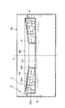
- Each of the cover plates 12 and 13 has the same shape as each other, and has a quadrangular shape in which the four corners are curved so as to match the shape of the opening 11x of the rectangular cylindrical body 11.
- the lid plate 12 is joined so as to close the upper opening portion 11x of the rectangular cylindrical body 11, while the lid plate 13 is joined so as to close the lower opening portion 11x of the rectangular cylindrical body 11. In this way, by closing the upper and lower openings 11x of the rectangular cylinder 11 with the cover plates 12 and 13, air can be enclosed in the floating body 10.
- each of the four side wall surfaces 11 y of the rectangular cylindrical body 11 On each of the four side wall surfaces 11 y of the rectangular cylindrical body 11, a pair of longitudinal reinforcing beads 111 formed between the upper and lower openings 11 x and a pair extending in a direction intersecting the longitudinal reinforcing beads 111.
- the horizontal reinforcing beads 112 and the rectangular reinforcing portions 113 (commonly called picture frames) formed so as to be surrounded by the vertical reinforcing beads 111 and the horizontal reinforcing beads 112 are formed by pressing.
- Each of the four side wall surfaces 11y is reinforced by the formation of the vertical reinforcing beads 111, the horizontal reinforcing beads 112, and the rectangular reinforcing portions 113, and as a result, the entire rectangular cylindrical body 11 is structurally reinforced.
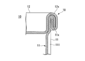
- the square cylinder 11 and the cover plate 12 are joined together by, for example, winding shown in FIGS. 4A and 4B.
- the other cover board 13 is not demonstrated in particular, it is joined to the square cylinder 11 by the double winding fastening similar to the cover board 12.
- the one opening portion 11x of the rectangular cylindrical body 11 expands while gently curving from the inside toward the outside.
- a flange 11a is formed.
- the edge portion 12x of the cover plate 12 has an inclined portion 12x1 that rises obliquely upward along the inner surface of the flange 11a, and a parallel portion 12x2 that continues to the inclined portion 12x1 and is substantially parallel to the central portion of the cover plate 12.
- a curled portion 12x3 that is continuous with the parallel portion 12x2 and is bent in an arc shape so as to go from the upper side to the lower side of the flange 11a.
- the said longitudinal reinforcement bead 111 (refer FIG. 3A) in which a front-end
- FIG. 4B shows a state after the double winding is performed in this manner.
- a winding portion 18 is formed at a joint portion between the opening portion 11 x of the rectangular tube body 11 and the edge portion 12 x of the cover plate 12.
- the portion of the vertical reinforcing bead 111 in the tightening portion 18 is crushed and further flattened during the tightening.
- both ends of the longitudinal reinforcing bead 111 are processed flat by the above-described processing of the flange 11a and the above-described winding tightening, and the portion between the ends flattened in this way, that is, the winding is tightened.
- the part other than the part keeps the original dent and functions as a longitudinal reinforcing bead 111 for reinforcement.
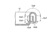
- the opening 11x of the rectangular cylinder 11 after double winding is an inclined part that is inclined obliquely from the inside of the square cylinder 11 to the outside.
- 11x1 a first linear portion 11x2 that is continuous with the inclined portion 11x1 and is linearly formed along the longitudinal direction (vertical direction) of the rectangular cylindrical body 11, and a linear cylindrical body 11 that is continuous with the first linear portion 11x2.
- the edge portion 12x of the lid plate 12 after double winding is bent from the center portion of the lid plate 12 toward the longitudinal direction (vertical direction) of the rectangular cylinder 11.
- a portion 12x4 a third straight portion 12x5 continuous with the second bent portion 12x4 and linearly formed in the longitudinal direction, and continuous with the third straight portion 12x5 and externally from the inside of the rectangular cylindrical body 11
- a third bent portion 12x6 folded back in a U-shape toward the direction, a fourth straight portion 12x7 connected to the third bent portion 12x6 and linearly formed along the longitudinal direction (vertical direction)
- the fourth bent portion 12x8 communicates with the fourth linear portion 12x7 and is folded back in a U-shape from the outside to the inside of the rectangular cylindrical body 11, and continues to the fourth bent portion 12x8.
- double winding refers to a method in which the curled portion 12x3 of the cover plate 12 is wound around the flange 11a of the quadrangular cylinder 11, and is crimped and joined. Since the cover plate 12 and the rectangular cylinder 11 are doubled, it is called double winding. And in this coiling
- the gap 151a that directly communicates with the internal space of the rectangular cylinder 11 and has a curved shape, and the longitudinal direction of the square cylinder 11 that is continuous with the gap 151a.
- a linear gap 151 extending in the (vertical direction), a gap 154a continuous with the gap 151 and folded back in a U-shape from the inside of the rectangular cylinder 11 to the outside, and continued to the gap 154a.
- a linear gap 154 extending along the longitudinal direction, a gap 153a continuous with the gap 154 and folded back in a U shape from the outside toward the inside, and a gap 153a continuous with the gap 153a.
- the gap 152a returning Ri includes said longitudinal direction extends along a linear gap 152 to further direct communication with the outer space of the rectangular tube body 11 with connected to the gap 152a, the.
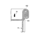
- the floating body 10 When the pontoon 220 is damaged and the liquid storage product OL enters the floating chamber E, the floating body 10 receives an external pressure P1 from the surroundings by the liquid storage product OL filling the external space as shown in FIG. 6A. Since the external pressure P1 is applied to the outer surface of the cover plate 12, the edge 12x of the cover plate 12 is pressed against the opening 11x of the rectangular cylinder 11, so that a part of the gap path (the contact portion 161 shown in the drawing) 162), line contact occurs along the shape of the opening 11x, and as a result, the gap path is blocked. By this blocking, it is possible to suppress as much as possible the liquid storage product OL that fills the periphery of the floating body 10 from entering the internal space of the floating body 10, and thus the buoyancy of the floating body 10 is maintained.
- the floating body 10 when a fire occurs and the floating body 10 is heated from the surroundings, as shown in FIG. 6B, the air confined in the inside is also heated to increase the pressure (internal pressure P2). Due to the internal pressure P2, the edge 12x of the cover plate 12 tends to be slightly separated from the opening 11x of the rectangular cylindrical body 11, so that the gap path is blocked (locations 161 and 162 described above). A gap is formed. As a result, the substantially spiral gap path that communicates between the internal space and the external space of the floating body 10 is formed, and the pressure increase in the internal space can be reliably released (exhausted) to the external space. . Therefore, the floating body 10 can maintain its buoyancy without being damaged.
- a sealing material is put in portions corresponding to the inclined portion 12x1, the parallel portion 12x2, and the curled portion 12x3 of the lid plate 12, and then the lid
- the plate 12 and the rectangular tube body 11 are wound and the four gaps 151 to 154 formed in the wound portion 18 are filled with the sealing material to improve the sealing performance.
- the sealing material is used because the function as a container cannot be exhibited at all when the liquid stored in the metal can leaks, and there is no structure without the sealing material.
- a sealing material in the inclined portion 12x1, the parallel portion 12x2, and the curled portion 12x3 of the lid plate 12 on the contrary. Absent. This is because if the sealing material is inserted, the gaps 151 to 154 are filled with the sealing material after winding. Normally, metal cans are used as containers, so a sealing material is essential. However, in the floating body 10 of the present embodiment, conversely, a gap is positively formed without using a sealing material. A configuration that cannot be conceived is adopted.
- the gap sizes of the four gaps 151 to 154 can be adjusted by increasing or decreasing the tightening pressure by the double tightening machine.
- the tightening thickness dimension T (hereinafter simply referred to as the T dimension) of the tightening portion 18 shown in FIG. 5 decreases and the clearance dimensions of the four clearances 151 to 154 decrease.
- the T dimension of the tightening portion 18 is increased, and the clearance dimensions of the four clearances 151 to 154 are increased.
- the four gaps 151 to 154 in the winding portion 18 serve as a gas (air) flow path between the internal space and the external space of the floating body 10 forming a metal can.
- the floating roof tank is made while minimizing the intrusion of the liquid storage OL (liquid) as much as possible (maintaining buoyancy as much as possible).
- the deformation of expansion and contraction of the floating body 10 due to heating at the time of 100 fires and cooling after quenching can be suppressed as much as possible.
- the average gap size (thickness) of the gaps 151, 152, 153, and 154 in the plane cross section at the 2 ⁇ ML position) is defined as follows.
- the thickness of the rectangular cylinder 11 is S 1 in the unit of mm
- the plate thickness of the cover plates 12 and 13 is the unit of S 2 in the unit of mm
- the thickness of the tightening portion 18 is T in the unit of mm
- the tightening is R
- the thickness T of the tightening portion 18 was changed by 0.10 mm within a range of 1.70 mm to 2.70 mm.
- the floating body 10 was immersed in water and left for 48 hours. Then, the amount of water that entered the internal space of the floating body 10 after 48 hours was measured. As the amount of water immersion, the test was performed 5 times, and the average value was obtained.
- Table 1 shows the thickness T of the tightening portion 18, the average gap size G calculated from Equation 1 above, and the amount of water immersion.
- Table 2 shows the relationship between the amount of water injected into the internal space of the floating body 10 and the submergence depth of the floating body 10, which was performed for confirmation.
- the submergence depth of the floating body 10 represents the degree of sinking when the floating body 10 in which an arbitrary amount of water has been poured into the internal space is left in the water, and is the most of the three sides of the floating body 10 described above. The depth is expressed by how long a long side (350.0 mm) is submerged from the water surface.
- the floating body 10 that has been poured (submerged) by about 500 ml has substantially the same submerged depth as compared with the floating body 10 that is not poured. That is, with a water injection amount (submerged amount) of about 500 ml, the floating body 10 can maintain sufficient buoyancy without affecting the buoyancy of the floating body 10.
- the floating bodies 10 shown in Table 1 in which the thickness T of the tightening portion 18 is 1.70 mm to 2.70 mm have sufficient buoyancy.
- the floating body 10 having a thickness T of the tightening portion 18 of 2.20 mm or less (an average gap dimension G of 175 ⁇ m or less) is preferable because the buoyancy can be maintained by making the water immersion as small as possible.
- the upper plate of the pontoon 220 was cooled with water, and the upper plate of the pontoon 220 was opened to rapidly cool the inside of the pontoon 220 in the air. As a result, it was rapidly cooled at 400 ° C. for about 9 minutes from when natural fire extinguishes (floating body temperature 700 ° C.) to when the upper plate of the pontoon 220 was opened (floating body temperature 300 ° C.). It was. However, some shrinkage deformation occurred in the floating body 10 while the upper plate of the pontoon 220 was opened and the inside of the pontoon 220 was rapidly cooled in the air. However, this contraction deformation is not contraction enough to reduce the buoyancy of the floating body 10.
- the distribution path of gas (air) becomes wider. Therefore, expansion and contraction deformation of the floating body 10 during heating and cooling are reduced.
- the performance required for the floating body 10 depends on whether emphasis is placed on buoyancy (sealing performance) or expansion / shrinkage deformation (air permeability) during heating and cooling. It is preferable to set the dimension and the average gap dimension G. All of the floating bodies 10 used in the above-described tests satisfy the performance related to the buoyancy (sealing property) and the expansion / contraction deformation (air permeability) required for the floating body 10. However, when the performance of either sealing performance or air permeability is regarded as important, the T dimension and the average gap dimension G of the floating body 10 may be appropriately set according to the request. As a result, deformation such as expansion and contraction due to temperature changes during a fire is reduced, and proper buoyancy can be maintained for a long period of time.
- the floating body 10 (18 liter square can) used in the above test has a smaller amount of liquid ingress while ensuring a certain degree of gas (air) air permeability. Therefore, the T dimension is preferably 1.90 mm or more and 2.20 mm or less, that is, the average gap dimension G is 100 ⁇ m or more and 175 ⁇ m or less.
- the dimension is 2.1 mm or more and 2.2 mm or less, that is, the average gap dimension G is 150 ⁇ m or more and 175 ⁇ m or less.
- the preferable range of the T dimension is a value that varies depending on the thickness of the rectangular cylinder 11 and the cover plates 12 and 13 used for the floating body 10 and the number of windings. Since the range of the average gap dimension G is the average dimension (thickness) of the gap, it is a value that does not depend on the plate thickness, the number of windings, etc. of the floating body 10. Therefore, when using the floating body 10 having a plate thickness and the number of windings other than those used in the above test, the average gap dimension G of the floating body 10 is controlled to be within the above-described preferable range. That's fine.
- a metal can (18 liter square can) was used as the floating body 10, but the present invention is not limited to this, and a metal body having a fire resistance and a metal lid are wound together. Any structure may be used as long as the internal space is hollow.
- the winding with which the square cylinder 11 (metal cylinder) and the cover plates 12 and 13 (metal end plate) are double-tightening (the number of turns is 2).
- the number of windings of the floating body 10 is not limited to this, and the number of windings may be changed as necessary.
- both the two opening parts 11x of the square cylinder 11 are used as the cover plates 12 and 13 using the square cylinder 11 and the cover plates 12 and 13 which have a pair of opening part 11x.
- the floating body 10 was formed.
- the floating body 10 is not limited to two places to be tightened, and it is sufficient that an opening is formed at least at one place and the space between the main body having the internal space and the lid body is tightened. In this case, since the overall length of the gap formed annularly along the opening 11x of the floating body 10 changes, the average gap dimension G may be controlled accordingly.
- each of the rectangular cylinder 11 and the cover plates 12 and 13 is not limited to the plate thickness used in the above test (the tube thickness 0.27 mm and the lid plate thickness 0.32 mm), and as necessary. May be changed. However, it is preferable that each of the plate thickness of the rectangular cylinder 11 and the plate thicknesses of the cover plates 12 and 13 is 0.20 mm to 0.32 mm. When a material having a thickness within this range is used, it is possible to manufacture the floating body 10 by winding the rectangular tube body 11 and the cover plates 12 and 13 using an existing can manufacturing process manufacturing apparatus. . Therefore, the capital investment cost can be suppressed and the manufacturing cost can be reduced.
- the rectangular (cuboid) floating body 10 is used, but the shape of the floating body 10 is not limited to this.
- the shape of the floating body 10 may be a round shape (cylindrical shape such as a drum can) or other shapes.
- the plurality of floating bodies 10 can be accommodated in the floating chamber E of the pontoon 220 with less spatial loss. Therefore, it is preferable because a larger buoyancy of the pontoon 220 can be secured.
- the floating body 10 of the present embodiment described above is summarized below.
- the floating body 10 of this embodiment is accommodated and used in the floating chamber E of the floating roof 200 of the floating roof type tank 100.
- the opening part 11x is formed in two places, and the metal square cylinder 11 (main body) which has internal space, and the opening part 11x are covered, and the edge part 12x is wound around this opening part 11x.
- Attached metal lid plates 12 and 13 (lid body) are provided. And between the opening part 11x and the edge part 12x, between the external space of the square cylinder 11 (main body) and the said internal space, the square cylinder 11 (main body) and the cover plates 12 and 13 are communicated.
- the gap path (first gap) that allows the approaching / separating operation between the (cover bodies); and the gap path (when the lid plates 12 and 13 (cover body) are closest to the rectangular cylinder 11 (main body))
- Contact portions 161 and 162 (first contact portions) that block the first gap) are provided.
- the square cylinder 11 (main body) has comprised the cylinder which has a pair of opening part 11x.
- lid plates 12 and 13 lid bodies
- the gap path (the first path) between both the lid plate 12 and the one opening 11x to which the lid plate 12 is attached and between the lid plate 13 and the other opening 11x to which the lid plate 13 is attached.
- a clearance) and contact portions 161 and 162 are provided.
- the floating body 10 of the present embodiment is a metal square can in which the cylindrical body 11 is square and the lid plates 12 and 13 (lid bodies) form a quadrangle.
- the tightening portion 18 (the portion to be tightened) is viewed in the cross section of FIG. 5 including the approaching and separating direction, the opening 11x of the rectangular cylinder 11 (main body) and the cover plate 12, 13 (lid) 12x is engaged with the edge 12x.
- each of the contact parts 161, 162 (first contact part) is formed in a ring shape along the opening part 11x, and the line contact part between the opening part 11x and the edge part 12x. It is.
- the number of windings of the winding is 2. As described above, the number of windings may be further increased as necessary.
- the thickness of the rectangular cylinder 11 (main body) is in the range of 0.20 mm to 0.32 mm. Further, the plate thicknesses of the cover plates 12 and 13 (lid bodies) are in the range of 0.20 mm to 0.32 mm.
- the floating body 10 which concerns on 2nd Embodiment of this invention is demonstrated below.
- the structure of the rectangular cylinder 11 (main body) is particularly different from that of the first embodiment. Therefore, the differences will be mainly described, and the other structures are assumed to be the same as those of the first embodiment. A duplicate description is omitted.
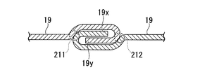
- the rectangular cylinder 11 of the first embodiment has a structure in which a rectangular metal plate is bent and formed into a quadrangular rectangular shape, and then two opposite sides are overlapped and welded. As described above, in this embodiment, winding is used instead of welding. This will be described below with reference to FIGS. 7B and 7C.
- the rectangular cylinder 11 has a cylindrical shape having a pair of the opening portions 11x by connecting the opposing two sides 19x and 19y of the rectangular metal plate 19 to each other. Yes. Then, this connection is a tightening, and the two sides 19x, 19y that communicate with each other between the inner space and the outer space of the rectangular cylindrical body 11 between the two sides 19x, 19y that are tightened are opposed to each other.
- a cylindrical gap 20 that allows an approaching / separating operation therebetween and cylindrical contact portions 211 and 212 that block the cylindrical gap 20 when the opposing two sides 19x and 19y are closest to each other are provided.
- the number of windings is 2 or more, this embodiment illustrates double winding. You may change the winding number of winding as needed.
- a sealing material is similarly applied to the rectangular cylinder 11 itself.
- the winding structure which provided the clearance gap without interposing is employ
- the air pressure in the internal space can be more reliably discharged by heating received in the event of a fire or the like. That is, as shown in FIG. 7B, for example, when the pontoon 220 is damaged and the liquid storage product OL enters the floating chamber E, the floating body 10 applies an external pressure from the surroundings by the liquid storage product OL filling the external space. receive.
- the rectangular cylinder 11 Since the two sides 19x and 19y of the rectangular cylinder 11 are pressed by this external pressure, the rectangular cylinder 11 has a portion of the cylindrical gap 20 (the cylinder abutting portions 211 and 212 shown in the drawing). Line contact along the longitudinal direction occurs, and as a result, communication between the internal space and the external space of the rectangular tube 11 is blocked. By this blocking, it is possible to suppress as much as possible the liquid storage product OL that fills the periphery of the floating body 10 from entering the internal space of the floating body 10, and thus the buoyancy of the floating body 10 is maintained. Moreover, as shown in FIG. 7C, for example, when a fire occurs and the floating body 10 is heated from the surroundings, the air confined in the internal space is also heated to increase the pressure.
- the two sides 19x and 19y of the rectangular cylinder 11 which are wound up tend to be slightly separated from each other, so that a gap is formed at the blocked location (the locations of the above-mentioned reference numerals 211 and 212). .
- the substantially spiral cylindrical gap 20 that communicates between the internal space and the external space of the floating body 10 is formed, and the pressure in the internal space is reliably released (exhausted) to the external space. Can do. Therefore, the floating body 10 can maintain its buoyancy without being damaged. Even if the separation distance is very small, air (gas) has a lower viscosity than the liquid storage product OL (liquid) and can be easily ventilated.
- the floating body 10 of the present embodiment described above adopts the following configuration in addition to the configuration of the first embodiment.
- the rectangular cylinder 11 (main body) is formed by folding a rectangular metal plate 19 into a rectangular cylinder and joining two sides 19x and 19y facing each other. Furthermore, this joining is made by winding, and the space between the two sides 19x and 19y thus tightened is communicated between the internal space and the external space of the rectangular cylinder 11 (main body), and the two sides
- the cylinder gap 20 (second gap) that allows an approaching and separating operation between 19x and 19y and the two sides 19x and 19y are closest to each other, the cylinder gap 20 (second gap) is blocked. Cylinder contact portions 211 and 212 (second contact portions) to be provided.
- the number of windings between the two sides 19x and 19y is two. As described above, the number of windings may be further increased as necessary.
- the cylindrical body contact portions 211 and 212 (second contact portions) are line contact portions between the two sides 19x and 19y.
- the rectangular cylinder 11 may employ a configuration in which the joining between the opposing two sides 19x and 19y of the rectangular metal plate 19 is joined by winding.
- the cylinder gap 20 that allows the relative approaching and separating operation between the two opposite sides 19x and 19y and the cylinder that blocks the cylinder gap 20 when the two opposite sides 19x and 19y are closest to each other.
- the contact portions 211 and 212 satisfy the performance of the buoyancy of the floating body 10 (sealing property when immersed in the pontoon) and suppression of expansion / contraction deformation (air permeability when heated from the surroundings).
- the floating body 10 of the present modification is housed and used in the floating chamber E of the floating roof 200 of the floating roof type tank 100. Then, the rectangular metal plate 19 is folded into a quadrangular cylindrical shape, and the rectangular cylinder 11 (main body) in which two sides 19x and 19y facing each other are joined; and the opening 11x of the rectangular cylindrical body 11 (main body) is covered. A fixed lid plate 12, 13 (lid body); and the joining is performed by tightening, and the rectangular cylinder 11 (main body) is provided between the two sides 19x and 19y that are tightened.
- a cylindrical gap 20 (third gap) that allows communication between the internal space and the external space and allows the approach and separation between the two sides 19x and 19y; and the two sides 19x and 19y are mutually connected
- cylinder contact portions 211 and 212 (third contact portions) that block the cylinder gap 20 (third gap) when they are closest to each other.
- the number of windings between the two sides 19x and 19y is 2 or more. As described above, the number of windings may be further increased as necessary.
- the cylindrical contact portions 211 and 212 (third contact portions) are line contact portions between the two sides 19x and 19y.
Landscapes
- Engineering & Computer Science (AREA)
- Mechanical Engineering (AREA)
- Filling Or Discharging Of Gas Storage Vessels (AREA)
- Tents Or Canopies (AREA)
- Rigid Containers With Two Or More Constituent Elements (AREA)
Abstract
Description
本願は、2011年01月14日に、日本国に出願された特願2011-005735号に基づき優先権を主張し、その内容をここに援用する。
(1)本発明の一態様は、浮き屋根式タンクの浮き屋根の浮室内に収容される浮き体であって、少なくとも一箇所に開口部が形成されて、かつ内部空間を有する金属製の本体と、前記開口部を覆うとともにこの開口部に対して縁部が巻締めで取り付けられた金属製の蓋体とを備え、前記開口部と前記縁部との間に、前記本体の外部空間と前記内部空間との間を連通させてかつ、前記本体及び前記蓋体間の接近離間動作を許容する第1の隙間と;前記本体に前記蓋体が最も接近した際に前記第1の隙間を遮断する第1の当接部と;が設けられている。
(2)上記(1)に記載の浮き体では、前記本体が、前記開口部を一対有する筒体をなし;この筒体の前記各開口部の各々に対して前記蓋体が前記巻締めで設けられ;前記各蓋体の一方及びこの一方の蓋体が取り付けられる一方の前記開口部間と、前記各蓋体の他方及び前記各開口部の他方間との双方に、前記第1の隙間及び前記第1の当接部が設けられている;構成を採用してもよい。
(3)上記(1)又は(2)に記載の浮き体では、前記筒体が角形でかつ前記各蓋体が四角形をなす、金属製角形状缶であってもよい。
(4)上記(1)~(3)のいずれか一項に記載の浮き体では、前記巻締めの部分を、前記接近離間方向を含む断面で見た場合に、前記本体の前記開口部と前記蓋体の前記縁部とが係止めしている構成を採用してもよい。
(5)上記(1)~(4)のいずれか一項に記載の浮き体では、前記第1の当接部が、前記開口部に沿って環状に形成された、前記開口部及び前記縁部間の線接触部分であってもよい。
(6)上記(1)~(5)のいずれか一項に記載の浮き体では、前記巻締めの巻き数が2以上であってもよい。
(7)上記(6)に記載の浮き体の場合、前記開口部及び前記縁部間の前記巻締めした部分を前記接近離間方向に沿った断面で見た場合に、前記第1の隙間が、前記接近離間方向に沿った複数本の直線状隙間部分と、これら直線状隙間部分間を繋いで折り返す、折り返し隙間部分とを有し;前記各直線状隙間部分を、それらの長さ方向の中間位置でかつ、前記接近離間方向に交差する断面で見た場合に、これら直線状隙間部分の平均隙間寸法が、100μm以上175μm以下の範囲内である;構成を採用してもよい。
(8)上記(1)~(7)のいずれか一項に記載の浮き体では、前記本体の板厚が0.20mm~0.32mmの範囲内であり;前記蓋体の板厚が0.20mm~0.32mmの範囲内である;構成を採用してもよい。
(9)上記(1)~(8)のいずれか一項に記載の浮き体では、前記本体が、矩形状の金属板を筒状に折って互いに対向する2辺を接合してなり;前記接合が巻締めでなされており、なおかつこの巻締められた前記2辺間に、前記本体の前記内部空間と前記外部空間との間を連通させてかつ、前記2辺間の接近離間動作を許容する第2の隙間と;前記2辺同士が互いに最も接近した際に、前記第2の隙間を遮断する第2の当接部と;が設けられている構成を採用してもよい。
(10)上記(9)に記載の浮き体の場合、前記2辺間における前記巻締めの巻き数が2以上であってもよい。
(11)上記(10)に記載の浮き体の場合、前記第2の当接部が、前記2辺間の線接触部分であってもよい。
(12)本発明の別の態様は、浮き屋根式タンクの浮き屋根の浮室内に収容される浮き体であって、矩形状の金属板を筒状に折って互いに対向する2辺を接合した本体と;この本体の開口部を覆って固定された蓋体と;を備え、前記接合が巻締めでなされており、なおかつこの巻締められた前記2辺間に、前記本体の内部空間と外部空間との間を連通させてかつ、前記2辺間の接近離間動作を許容する第3の隙間と;前記2辺同士が互いに最も接近した際に、前記第3の隙間を遮断する第3の当接部と;が設けられている。
(13)上記(12)に記載の浮き体の場合、前記2辺間における前記巻締めの巻き数が2以上であってもよい。
(14)上記(12)に記載の浮き体の場合、前記第3の当接部が、前記2辺間の線接触部分であってもよい。
これについて説明すると、本態様の浮き体は金属製であるため、従来提案の樹脂製の浮き体とは比較にならないほど耐火性に優れている。なお、従来提案の樹脂製の浮き体をただ単に金属製にしただけでは、本願課題を解決できない点に注意が必要である。
すなわち、浮力を得るために内部に空気を入れてただ単に密封した金属製の浮き体を想定すると、これに対し、例えば火災発生時等の火炎による加熱を受けた場合、内部に密封された空気が加熱されて内圧が上昇してしまうことを禁じ得ない。しかも、内圧を受けた際の変形度合いが樹脂製のものに比べて制限される金属製の浮き体の場合、内圧が許容値を超えてしまうと破損してしまう虞がある。
一方、本態様の浮き体では、本体及び蓋体間の接近離間動作を許容する第1の隙間が設けられているため、内部空間において過度の内圧上昇が生じた場合、この内圧を利用して第1の隙間が確保されるように蓋体を本体から僅かに離間させることができる。そして、前記第1の隙間を介して、浮き体の内部空間における過度の内圧を外部空間に向かって開放させることができる。しかも、このような調整機能を、安全弁等の余計な部品を用いることなく、巻締めだけで達成しているため、低コストで製造することができる上に、浮き体自体の軽量化にも貢献している。
また、本態様の浮き体では、浮き室内に液体が浸入してきた際に加熱による過度の内圧上昇が無かったとしても、今度は、液体が浮き体に対して外圧として作用する。そして、外圧を受けた蓋体が本体に向かって押し付けられるがごとく僅かに接近動作を行い、その結果として第1の隙間が第1の当接部において自動的に遮断される。よって、浮き体の内部空間に空気が密封されるため、十分な浮力を得ることができる。
図1は、本発明の第1実施形態に係る浮き体10をポンツーン220内に収容した浮き屋根200と、浮き屋根式タンク100とを示す縦断面図である。なお、同図1において符号CLは浮き屋根式タンク100の中心軸線を示す。
浮き屋根200は、鋼板で形成されており、円盤状の屋根本体210と;この屋根本体210の上面周縁に沿ってリング状に形成され、なおかつ縦断面視した場合にリングの中心から外方に向けて高さが漸次に高くなるポンツーン220と;を有している。
ポンツーン220は、屋根本体210に対してこの周縁より鉛直方向上方に切り立つように溶接固定された円筒状の外壁220aと、この外壁220a内に同軸をなすように配置され、屋根本体210の中央部上面より鉛直方向上方に切り立つように溶接固定された円筒状の内壁220bと、これら外壁220a及び内壁220b間に挟まれる空間を塞ぐように、これら外壁220a及び内壁220bの各上縁に溶接固定されたリング状の上壁220cとを備えている。そして、このポンツーン220は、その内部に、リング状の空洞である浮室Eが形成されており、この浮室E内に封じ込められた空気により浮力を発生させることができる。よって、このポンツーン220の浮力によって、浮き屋根200全体が浮き屋根式タンク100に貯蔵された液体貯蔵物OLの上面を覆って浮くようになっている。
ポンツーン220の浮室E内には多数の浮き体10が収容されているが、浮き体10自体が中空で軽量のため、ポンツーン220全体としての浮力は維持できる。浮き体10の具体的な構造については後述する。
図3Aに示すように、浮き体10(金属製缶)は、金属薄板(例えば、すずメッキ鋼板、ティンフリースチール等)からなり、4箇所のコーナー部にカーブが形成された四角筒体(金属製の本体をなす筒体)11と;同じく金属薄板からなる一対の蓋板12、13(蓋体をなす金属製端板)と;を一体に組み合わせた構造となっている。
そして、四角筒体11のフランジ11aに対して、蓋板12における縁部12xのカール部12x3を被せた状態で、四角筒体11の一方の開口部11x(端縁部)に蓋板12がセットされる。この状態で、図示しない二重巻締め機によって蓋板12のカール部12x3を含む縁部12xと、四角筒体11のフランジ11aとが一体に重ねられた状態で二重巻締めされる。
このようにして二重巻き締めを行った後の状態を図4Bに示す。この図4Bに示すように、四角筒体11の開口部11xと蓋板12の縁部12xとの接合部に巻締め部18が形成される。この巻締め部18内の縦補強ビード111の部分は、巻締めの際に押しつぶされてさらに平坦になる。よって、縦補強ビード111は、その両端部分が、上記のフランジ11aの加工と上記の巻き締め加工とにより平坦に加工され、このようにして平坦化された両端間の部分、すなわち巻き締めされた部分以外が本来の凹みを保ち、補強のための縦補強ビード111として機能を発揮する。
この形状について詳細に説明すると、図4Cに示すように、二重巻き締め後における四角筒体11の開口部11xは、四角筒体11の内方から外方に向かって斜めに傾斜した傾斜部11x1と、この傾斜部11x1に連なるとともに四角筒体11の長手方向(上下方向)に沿って直線状に形成された第1直線部11x2と、この第1直線部11x2に連なるとともに四角筒体11の内方から外方に向かってU字状に折り返された第1折り曲げ部11x3と、この第1折り曲げ部11x3に連なるとともに前記長手方向(上下方向)に沿って直線状に形成された第2直線部11x4と、を備えている。
そして、この巻締め部18では、断面U字状となるように折り返された四角筒体11の一方の開口部11x(端縁部)と、2度の折返しで渦巻状に形成された蓋板12の縁部12xとが係合した状態となる。その結果、巻締め部18では、図5に示すように、相互に係合する、四角筒体11の一方の開口部11xと蓋板12の縁部12xとの間に、互いに連通する4つの隙間151、152、153、154を含む隙間経路が形成される。
以上説明のように、四角筒体11の開口部11xに対して蓋板12の縁部12xが接近離間することで、前記隙間経路が開通又は遮断する。
一方、本実施形態の浮き体10としての金属製缶を製造する場合には、逆に、蓋板12の傾斜部12x1、平行部12x2、及び、カール部12x3内にシール材を入れることが好ましくない。シール材を挟み込んでしまうと、巻き締め後に上記の隙間151~154がシール材により埋められてしまうからである。金属製缶は通常、容器として用いられるためにシール材を必須としていたが、本実施形態の浮き体10では逆にシール材を使用せずに隙間を積極的に形成するという、従来の常識では想到し得ない構成を採用している。
板厚が0.27mmである、一対の開口部11xを有する四角筒体11と、板厚が0.32mmである蓋板12及び13とを用いて、下記サイズを有する角形状の金属製である浮き体10(18リットル角形状缶)を二重巻締め(巻き数が2)により製造した。そして、この浮き体10の巻締め部18における前記T寸法を変化させて、浮き体10の浸水試験及び加熱冷却試験を行った。
・浮き体10の3辺の外形寸法:350.0mm×238.0mm×238.0mm (各辺の誤差は±1.0mm以内)
・浮き体10の質量:1019g
・浮き体10の内部空間の容量:19.5L(リットル)
G=1000×{T-S1×R-S2×(R+1)}÷2R・・・(式1)
巻締め部18の厚さTを1.70mm~2.70mmの範囲内で0.10mmずつ変化させた。この浮き体10を水に水没させて48時間放置した。そして48時間後の浮き体10の内部空間に浸入した水量を測定した。浸水量として、試験をそれぞれ5回実施して、その平均値を求めた。表1に、巻締め部18の厚さTと、上記式1から計算される平均隙間寸法Gと、浸水量とを示す。


(1)試験1
T=1.7mm(G=50μm)及びT=1.9mm(G=100μm)の浮き体10を、電気炉を用いて、750℃に加熱して8時間30分保持した。その後、炉内で16時間かけて80℃まで徐冷した。80℃となった時点で、浮き体10を電気炉から取り出して空気中で急冷した。その結果、浮き体10に若干の収縮変形が発生した。しかし、この収縮変形は、浮き体10の浮力を低下させるほどの収縮ではない。
(2)試験2
T=1.8mm(G=75μm)の浮き体10を、電気炉を用いて、750℃に加熱して8時間30分保持した。その後、炉内で40時間かけて30℃まで徐冷した。30℃となった時点で、浮き体10を電気炉から取り出した。その結果、浮き体10に収縮変形は発生しなかった。
(3)試験3
T=2.0mm(G=125μm)の浮き体10を、電気炉を用いて、750℃まで昇温した。750℃に到達直後、電気炉のヒーターをオフにして、炉内で30分かけて300℃まで冷却した。300℃となった時点で、浮き体10を電気炉から取り出して空気中で急冷した。その結果、電気炉から取り出した時点(浮き体温度300℃)では、浮き体10に収縮変形が生じていなかったが、空気中での急冷中に浮き体10に若干の収縮変形が発生した。しかし、この収縮変形は、浮き体10の浮力を低下させるほどの収縮ではない。
(4)試験4
T=2.1mm(G=150μm)及びT=2.2(G=175μm)の浮き体10を、電気炉を用いて、750℃まで昇温した。750℃に到達直後、電気炉のヒーターをオフにして、炉内で30分かけて300℃まで冷却した。300℃となった時点で、浮き体10を電気炉から取り出して空気中で急冷した。その結果、浮き体10に収縮変形は発生しなかった。
(5)実機サイズのポンツーン220のリング火災実験
実機サイズのポンツーン220に、T=1.8mm(G=75μm)の浮き体10を収容して火災実験を行った。ポンツーン220を外周部に沿ってリング状に12時間燃焼させた。この際、ポンツーン220内部の浮き体10の最高到達温度は750℃となった。ポンツーン220が自然鎮火した後、ポンツーン220上板を水冷し、そして、ポンツーン220上板を開放して、空気中でポンツーン220内部を急冷した。その結果、自然鎮火時(浮き体温度700℃)からポンツーン220上板開放時(浮き体温度300℃)までの約9分間で400℃急冷されたが、浮き体10に収縮変形は発生しなかった。しかし、ポンツーン220上板を開放して空気中でポンツーン220内部を急冷中に、浮き体10に若干の収縮変形が発生した。しかし、この収縮変形は、浮き体10の浮力を低下させるほどの収縮ではない。
(1)T=1.7mm(G=50μm)、T=1.8mm(G=75μm)、T=1.9mm(G=100μm)、T=2.0mm(G=125μm)、T=2.1mm(G=150μm)、及び、T=2.2.mm(G=175μm)である浮き体10のいずれも、750℃までの加熱による破損はない。
(2)上記のいずれの浮き体10も、上記加熱後に徐冷されるのであれば、浮き体10に収縮変形(凹み)は発生しない。
(3)T=2.1mm(G=150μm)、及び、T=2.2mm(G=175μm)である浮き体10は、加熱後の急冷によっても収縮変形(凹み)は発生しない。
(4)T=1.7mm(G=50μm)、T=1.8mm(G=75μm)、T=1.9mm(G=100μm)、及び、T=2.0mm(G=125μm)、である浮き体10は、加熱後の急冷によって収縮変形が生じるが、浮き体10の浮力を低下させるほどの収縮ではない。
また、上記試験及び上記実施形態では、四角筒体11(金属製筒体)と蓋板12及び13(金属製端板)との巻締めが二重巻締め(巻き数が2)である浮き体10を用いたが、浮き体10の巻き数はこれに限られず、必要に応じて巻き数を変更してもよい。
(1)本実施形態の浮き体10は、浮き屋根式タンク100の浮き屋根200の浮室E内に収容されて用いられる。そして、2箇所に開口部11xが形成されて、かつ内部空間を有する金属製の四角筒体11(本体)と、開口部11xを覆うとともにこの開口部11xに対して縁部12xが巻締めで取り付けられた金属製の蓋板12,13(蓋体)とを備える。そして、開口部11xと縁部12xとの間に、四角筒体11(本体)の外部空間と前記内部空間との間を連通させてかつ、四角筒体11(本体)及び蓋板12,13(蓋体)間の接近離間動作を許容する前記隙間経路(第1の隙間)と;四角筒体11(本体)に蓋板12,13(蓋体)が最も接近した際に前記隙間経路(第1の隙間)を遮断する当接部分161,162(第1の当接部)と;が設けられている。
(4)そして、巻締め部18(前記巻締めの部分)を、前記接近離間方向を含む図5の断面で見た場合に、四角筒体11(本体)の開口部11xと蓋板12,13(蓋体)の縁部12xとが係止めしている。
(5)そして、当接部分161,162(第1の当接部)のそれぞれが、前記開口部11xに沿って環状に形成された、前記開口部11x及び前記縁部12x間の線接触部分である。
(6)そして、前記巻締めの巻き数が2である。なお、前述の通り、必要に応じて巻き締めの巻き数をさらに増やしてもよい。
続いて、本発明の第2実施形態に係る浮き体10について以下に説明する。本実施形態では、四角筒体11(本体)の構造が上記第1実施形態と特に異なっているので、その相違点を中心に説明し、その他構造については上記第1実施形態と同様であるとして重複する説明を省略する。
すなわち、図7Bに示すように、例えばポンツーン220が破損して浮室E内に液体貯蔵物OLが浸入してきた場合、浮き体10は、その外部空間を満たす液体貯蔵物OLによる外圧を周囲より受ける。この外圧により、四角筒体11の巻締められた2辺19xと19yとが押し付けられるため、前記筒体隙間20の一部(図示の筒体当接部分211,212)において四角筒体11の長手方向に沿った線接触が生じ、その結果として、四角筒体11の内部空間と外部空間との間を連通が遮断される。この遮断により、浮き体10の周囲を満たす液体貯蔵物OLが浮き体10の内部空間に浸入してくるのを極力抑えることができるので、浮き体10の浮力が維持される。
また、図7Cに示すように、例えば火災が発生して浮き体10が周囲より加熱された場合には、その内部空間に封じ込められた空気も加熱されて昇圧する。この内圧により、四角筒体11の巻締められた2辺19xと19yとが僅かに離間しようとするため、前記遮断されていた箇所(前述の符号211,212の箇所)に隙間が形成される。その結果、浮き体10の内部空間と外部空間との間を連通させる略渦巻き状の前記筒体隙間20が形成され、前記内部空間内の昇圧を確実に前記外部空間に逃がす(排圧する)ことができる。よって、浮き体10は破損することなくその浮力を維持することができる。なお、前記離間の距離が例え微少であっても、空気(気体)は液体貯蔵物OL(液体)よりも粘性が低いので、容易に通気することが可能である。
(9)四角筒体11(本体)を、矩形状の金属板19を四角形筒状に折って互いに対向する2辺19x、19yを接合している。さらに、この接合が巻締めでなされており、なおかつこの巻締められた2辺19x、19y間に、四角筒体11(本体)の内部空間と外部空間との間を連通させてかつ、2辺19x、19y間の接近離間動作を許容する筒体隙間20(第2の隙間)と、2辺19x、19y同士が互いに最も接近した際に、前記筒体隙間20(第2の隙間)を遮断する筒体当接部分211,212(第2の当接部)と、が設けられている。
(10)そして、2辺19x、19y間における前記巻締めの巻き数が2である。なお、前述の通り、必要に応じて巻き締めの巻き数をさらに増やしてもよい。
(11)そして、前記筒体当接部分211,212(第2の当接部)が、2辺19x、19y間の線接触部分となっている。
(12)本変形例の浮き体10は、浮き屋根式タンク100の浮き屋根200の浮室E内に収容されて用いられる。そして、矩形状の金属板19を四角形筒状に折って互いに対向する2辺19x、19yを接合した四角筒体11(本体)と;この四角筒体11(本体)の開口部11xを覆って固定された蓋板12,13(蓋体)と;を備え、前記接合が巻締めでなされており、なおかつこの巻締められた前記2辺19x、19y間に、前記四角筒体11(本体)の内部空間と外部空間との間を連通させてかつ、前記2辺19x、19y間の接近離間動作を許容する筒体隙間20(第3の隙間)と;前記2辺19x、19y同士が互いに最も接近した際に、前記筒体隙間20(第3の隙間)を遮断する筒体当接部分211,212(第3の当接部)と;が設けられている。
(13)そして、2辺19x、19y間における前記巻締めの巻き数が2以上である。なお、前述の通り、必要に応じて巻き締めの巻き数をさらに増やしてもよい。
(14)そして、前記筒体当接部分211,212(第3の当接部)が、2辺19x、19y間の線接触部分となっている。
11 四角筒体(本体、筒体)
11a フランジ
11x 開口部
12,13 蓋板(蓋体)
12x 縁部
12x1 傾斜部
12x2 平行部
12x3 カール部
151、152、153、154 隙間(直線状隙間部分、第1の隙間)
152a,153a,154a 隙間(折り返し隙間部分、第1の隙間)
161、162 当接部分(第1の当接部)
18 巻締め部
19 金属板
19x,19y 対向する2辺
20 筒体隙間(第2の隙間、第3の隙間)
211,212 筒体当接部分(第2の当接部、第3の当接部)
100 浮き屋根式タンク
200 浮き屋根
210 屋根本体
220 ポンツーン
221 シール
223 マンホール
E 浮室
T 巻締厚寸法
Claims (14)
- 浮き屋根式タンクの浮き屋根の浮室内に収容される浮き体であって、
少なくとも一箇所に開口部が形成されて、かつ内部空間を有する金属製の本体と、前記開口部を覆うとともにこの開口部に対して縁部が巻締めで取り付けられた金属製の蓋体とを備え、
前記開口部と前記縁部との間に、
前記本体の外部空間と前記内部空間との間を連通させてかつ、前記本体及び前記蓋体間の接近離間動作を許容する第1の隙間と;
前記本体に前記蓋体が最も接近した際に前記第1の隙間を遮断する第1の当接部と;
が設けられていることを特徴とする浮き体。 - 前記本体が、前記開口部を一対有する筒体をなし;
この筒体の前記各開口部の各々に対して前記蓋体が前記巻締めで設けられ;
前記各蓋体の一方及びこの一方の蓋体が取り付けられる一方の前記開口部間と、前記各蓋体の他方及び前記各開口部の他方間との双方に、前記第1の隙間及び前記第1の当接部が設けられている;
ことを特徴とする請求項1に記載の浮き体。 - 金属製角形状缶であることを特徴とする請求項1に記載の浮き体。
- 前記巻締めの部分を、前記接近離間方向を含む断面で見た場合に、前記本体の前記開口部と前記蓋体の前記縁部とが係止めしていることを特徴とする請求項1に記載の浮き体。
- 前記第1の当接部が、前記開口部に沿って環状に形成された、前記開口部及び前記縁部間の線接触部分であることを特徴とする請求項1に記載の浮き体。
- 前記巻締めの巻き数が2以上であることを特徴とする請求項1に記載の浮き体。
- 前記開口部及び前記縁部間の前記巻締めした部分を前記接近離間方向に沿った断面で見た場合に、前記第1の隙間が、前記接近離間方向に沿った複数本の直線状隙間部分と、これら直線状隙間部分間を繋いで折り返す、折り返し隙間部分とを有し;
前記各直線状隙間部分を、それらの長さ方向の中間位置でかつ、前記接近離間方向に交差する断面で見た場合に、これら直線状隙間部分の平均隙間寸法が、100μm以上175μm以下の範囲内である;
ことを特徴とする請求項6に記載の浮き体。 - 前記本体の板厚が0.20mm~0.32mmの範囲内であり;
前記蓋体の板厚が0.20mm~0.32mmの範囲内である;
ことを特徴とする請求項1に記載の浮き体。 - 前記本体が、矩形状の金属板を筒状に折って互いに対向する2辺を接合してなり;
前記接合が巻締めでなされており、なおかつこの巻締められた前記2辺間に、前記本体の前記内部空間と前記外部空間との間を連通させてかつ、前記2辺間の接近離間動作を許容する第2の隙間と;
前記2辺同士が互いに最も接近した際に、前記第2の隙間を遮断する第2の当接部と;
が設けられていることを特徴とする請求項1~8の何れか1項に記載の浮き体。 - 前記2辺間における前記巻締めの巻き数が2以上であることを特徴とする請求項9に記載の浮き体。
- 前記第2の当接部が、前記2辺間の線接触部分であることを特徴とする請求項10に記載の浮き体。
- 浮き屋根式タンクの浮き屋根の浮室内に収容される浮き体であって、
矩形状の金属板を筒状に折って互いに対向する2辺を接合した本体と;
この本体の開口部を覆って固定された蓋体と;
を備え、
前記接合が巻締めでなされており、なおかつこの巻締められた前記2辺間に、
前記本体の内部空間と外部空間との間を連通させてかつ、前記2辺間の接近離間動作を許容する第3の隙間と;
前記2辺同士が互いに最も接近した際に、前記第3の隙間を遮断する第3の当接部と;
が設けられていることを特徴とする浮き体。 - 前記2辺間における前記巻締めの巻き数が2以上であることを特徴とする請求項12に記載の浮き体。
- 前記第3の当接部が、前記2辺間の線接触部分であることを特徴とする請求項12に記載の浮き体。
Priority Applications (5)
| Application Number | Priority Date | Filing Date | Title |
|---|---|---|---|
| CN201280004988.8A CN103298714B (zh) | 2011-01-14 | 2012-01-12 | 浮体 |
| JP2012530018A JP5405670B2 (ja) | 2011-01-14 | 2012-01-12 | 浮き体 |
| EP12734557.7A EP2664561A4 (en) | 2011-01-14 | 2012-01-12 | FLOATING BODY |
| RU2013132012/12A RU2553197C2 (ru) | 2011-01-14 | 2012-01-12 | Плавающее тело |
| US13/978,838 US20130284741A1 (en) | 2011-01-14 | 2012-01-12 | Floating body |
Applications Claiming Priority (2)
| Application Number | Priority Date | Filing Date | Title |
|---|---|---|---|
| JP2011005735 | 2011-01-14 | ||
| JP2011-005735 | 2011-01-14 |
Publications (1)
| Publication Number | Publication Date |
|---|---|
| WO2012096334A1 true WO2012096334A1 (ja) | 2012-07-19 |
Family
ID=46507226
Family Applications (1)
| Application Number | Title | Priority Date | Filing Date |
|---|---|---|---|
| PCT/JP2012/050446 Ceased WO2012096334A1 (ja) | 2011-01-14 | 2012-01-12 | 浮き体 |
Country Status (6)
| Country | Link |
|---|---|
| US (1) | US20130284741A1 (ja) |
| EP (1) | EP2664561A4 (ja) |
| JP (1) | JP5405670B2 (ja) |
| CN (1) | CN103298714B (ja) |
| RU (1) | RU2553197C2 (ja) |
| WO (1) | WO2012096334A1 (ja) |
Cited By (1)
| Publication number | Priority date | Publication date | Assignee | Title |
|---|---|---|---|---|
| KR20200024872A (ko) * | 2017-08-29 | 2020-03-09 | 포샨 순더 메이디 일렉트리컬 히팅 어플라이언시스 메뉴팩쳐링 코., 리미티드 | 조리 장치의 교반 장치 및 조리 장치 |
Families Citing this family (1)
| Publication number | Priority date | Publication date | Assignee | Title |
|---|---|---|---|---|
| KR102368719B1 (ko) * | 2021-08-27 | 2022-02-25 | 손용엽 | 유류 저장 탱크의 플로팅 커버용 다각형 폰툰 |
Citations (8)
| Publication number | Priority date | Publication date | Assignee | Title |
|---|---|---|---|---|
| JPS5439800B1 (ja) * | 1976-12-22 | 1979-11-29 | ||
| JPS5824867A (ja) | 1981-08-06 | 1983-02-14 | Seiko Epson Corp | 水晶振動子の特性測定装置 |
| JPH0411991Y2 (ja) * | 1986-06-02 | 1992-03-24 | ||
| JPH04239489A (ja) * | 1991-01-17 | 1992-08-27 | Misawa Homes Co Ltd | フロート蓋 |
| JP2006026638A (ja) * | 2004-07-12 | 2006-02-02 | Honshu Seikan Kk | 角形状缶 |
| JP2006143291A (ja) | 2004-11-22 | 2006-06-08 | Idemitsu Eng Co Ltd | 浮屋根式貯蔵タンク |
| JP4172846B2 (ja) * | 1998-06-26 | 2008-10-29 | 株式会社フジタ | 水位追従式水中ポンプ |
| JP4229235B2 (ja) * | 2003-11-27 | 2009-02-25 | 株式会社石井鐵工所 | 浮屋根の浮力増強構造 |
Family Cites Families (8)
| Publication number | Priority date | Publication date | Assignee | Title |
|---|---|---|---|---|
| GB513316A (en) * | 1938-03-25 | 1939-10-10 | John Arthur Dove | Improvements in the method of jointing sheet metal |
| US3054526A (en) * | 1959-04-25 | 1962-09-18 | Mercier Maurice | Fluid-tight packing for floating-rooftype hydrocarbon tanks |
| US3587911A (en) * | 1969-04-01 | 1971-06-28 | Olin Mathieson | Floating deck for storage tank |
| CN2233912Y (zh) * | 1995-09-11 | 1996-08-28 | 高秀珍 | 组合式浮盘 |
| JPH11124193A (ja) * | 1997-10-21 | 1999-05-11 | Idemitsu Eng Co Ltd | 浮屋根式貯蔵タンク |
| JP2006324070A (ja) * | 2005-05-17 | 2006-11-30 | Honda Motor Co Ltd | 蓄電池 |
| CN200964277Y (zh) * | 2006-07-26 | 2007-10-24 | 张凤球 | 储罐用的金属结构浮筒式内浮盘 |
| US7922026B2 (en) * | 2007-03-08 | 2011-04-12 | Skw Trust | Degassing container |
-
2012
- 2012-01-12 WO PCT/JP2012/050446 patent/WO2012096334A1/ja not_active Ceased
- 2012-01-12 EP EP12734557.7A patent/EP2664561A4/en not_active Withdrawn
- 2012-01-12 CN CN201280004988.8A patent/CN103298714B/zh active Active
- 2012-01-12 JP JP2012530018A patent/JP5405670B2/ja not_active Expired - Fee Related
- 2012-01-12 US US13/978,838 patent/US20130284741A1/en not_active Abandoned
- 2012-01-12 RU RU2013132012/12A patent/RU2553197C2/ru not_active IP Right Cessation
Patent Citations (8)
| Publication number | Priority date | Publication date | Assignee | Title |
|---|---|---|---|---|
| JPS5439800B1 (ja) * | 1976-12-22 | 1979-11-29 | ||
| JPS5824867A (ja) | 1981-08-06 | 1983-02-14 | Seiko Epson Corp | 水晶振動子の特性測定装置 |
| JPH0411991Y2 (ja) * | 1986-06-02 | 1992-03-24 | ||
| JPH04239489A (ja) * | 1991-01-17 | 1992-08-27 | Misawa Homes Co Ltd | フロート蓋 |
| JP4172846B2 (ja) * | 1998-06-26 | 2008-10-29 | 株式会社フジタ | 水位追従式水中ポンプ |
| JP4229235B2 (ja) * | 2003-11-27 | 2009-02-25 | 株式会社石井鐵工所 | 浮屋根の浮力増強構造 |
| JP2006026638A (ja) * | 2004-07-12 | 2006-02-02 | Honshu Seikan Kk | 角形状缶 |
| JP2006143291A (ja) | 2004-11-22 | 2006-06-08 | Idemitsu Eng Co Ltd | 浮屋根式貯蔵タンク |
Non-Patent Citations (1)
| Title |
|---|
| See also references of EP2664561A4 |
Cited By (2)
| Publication number | Priority date | Publication date | Assignee | Title |
|---|---|---|---|---|
| KR20200024872A (ko) * | 2017-08-29 | 2020-03-09 | 포샨 순더 메이디 일렉트리컬 히팅 어플라이언시스 메뉴팩쳐링 코., 리미티드 | 조리 장치의 교반 장치 및 조리 장치 |
| KR102231456B1 (ko) | 2017-08-29 | 2021-03-23 | 포샨 순더 메이디 일렉트리컬 히팅 어플라이언시스 메뉴팩쳐링 코., 리미티드 | 조리 장치의 교반 장치 및 조리 장치 |
Also Published As
| Publication number | Publication date |
|---|---|
| CN103298714A (zh) | 2013-09-11 |
| CN103298714B (zh) | 2015-06-17 |
| EP2664561A1 (en) | 2013-11-20 |
| US20130284741A1 (en) | 2013-10-31 |
| RU2553197C2 (ru) | 2015-06-10 |
| RU2013132012A (ru) | 2015-02-20 |
| EP2664561A4 (en) | 2015-09-23 |
| JPWO2012096334A1 (ja) | 2014-06-09 |
| JP5405670B2 (ja) | 2014-02-05 |
Similar Documents
| Publication | Publication Date | Title |
|---|---|---|
| JP5722793B2 (ja) | 極低温液体貯蔵タンク | |
| CN112368506B (zh) | 设置有波纹状接合元件的液密容器 | |
| JP2010525278A (ja) | 独立型波形lngタンク | |
| KR101375262B1 (ko) | 액화천연가스 저장탱크의 1차 방벽의 보강 부재용 고정 구조체 | |
| KR20120136319A (ko) | 액화천연가스 저장탱크의 펌프타워 베이스서포트 구조체 | |
| US3882591A (en) | Method of constructing a low temperature liquefied gas tank of a membrane type | |
| KR101444313B1 (ko) | 액화천연가스 저장탱크의 펌프타워 베이스서포트 구조체 | |
| KR20190040208A (ko) | 불침투성 벽체 구조물 | |
| KR20200083496A (ko) | 복수의 영역을 갖는 밀폐 및 단열 탱크 | |
| CN110998170B (zh) | 低温流体储存罐 | |
| JP5405670B2 (ja) | 浮き体 | |
| KR20230106152A (ko) | 액화 가스용 저장 탱크의 리퀴드 돔 | |
| KR20120136320A (ko) | 베이스서포트 구조체와 저장탱크 단열방벽 간의 연결구조체 | |
| US11830666B2 (en) | Tank for liquid-filled shell transformers or shell reactors | |
| KR102438160B1 (ko) | 유체 밀폐되고 단열된 유체 저장용 탱크 | |
| US11953154B2 (en) | Method and system for pressure relief in a multi chamber vessel | |
| KR101403621B1 (ko) | 액화천연가스 저장용기의 구조 및 제작방법 | |
| KR102498646B1 (ko) | 액화가스 저장탱크 및 이를 포함하는 선박 | |
| KR20150058645A (ko) | 화물창 | |
| JP7695251B2 (ja) | 液化ガス輸送タンク用のダブルアクセスハッチ | |
| KR20150145353A (ko) | 액체저장탱크 | |
| KR20220125329A (ko) | 액화가스 저장시설 | |
| KR20200037304A (ko) | 밀봉되고 단열된 탱크 | |
| KR102839775B1 (ko) | 액화 가스를 위한 저장 탱크의 리퀴드 돔 | |
| US20260077942A1 (en) | Seam assembly and methods |
Legal Events
| Date | Code | Title | Description |
|---|---|---|---|
| WWE | Wipo information: entry into national phase |
Ref document number: 2012530018 Country of ref document: JP |
|
| 121 | Ep: the epo has been informed by wipo that ep was designated in this application |
Ref document number: 12734557 Country of ref document: EP Kind code of ref document: A1 |
|
| WWE | Wipo information: entry into national phase |
Ref document number: 13978838 Country of ref document: US |
|
| REEP | Request for entry into the european phase |
Ref document number: 2012734557 Country of ref document: EP |
|
| WWE | Wipo information: entry into national phase |
Ref document number: 2012734557 Country of ref document: EP |
|
| NENP | Non-entry into the national phase |
Ref country code: DE |
|
| ENP | Entry into the national phase |
Ref document number: 2013132012 Country of ref document: RU Kind code of ref document: A |