WO2012096540A2 - Élément chauffant et procédé de production pour celui-ci - Google Patents
Élément chauffant et procédé de production pour celui-ci Download PDFInfo
- Publication number
- WO2012096540A2 WO2012096540A2 PCT/KR2012/000323 KR2012000323W WO2012096540A2 WO 2012096540 A2 WO2012096540 A2 WO 2012096540A2 KR 2012000323 W KR2012000323 W KR 2012000323W WO 2012096540 A2 WO2012096540 A2 WO 2012096540A2
- Authority
- WO
- WIPO (PCT)
- Prior art keywords
- heating element
- heat generating
- heating
- conductive
- pattern
- Prior art date
- Legal status (The legal status is an assumption and is not a legal conclusion. Google has not performed a legal analysis and makes no representation as to the accuracy of the status listed.)
- Ceased
Links
Images





Classifications
-
- H—ELECTRICITY
- H05—ELECTRIC TECHNIQUES NOT OTHERWISE PROVIDED FOR
- H05B—ELECTRIC HEATING; ELECTRIC LIGHT SOURCES NOT OTHERWISE PROVIDED FOR; CIRCUIT ARRANGEMENTS FOR ELECTRIC LIGHT SOURCES, IN GENERAL
- H05B3/00—Ohmic-resistance heating
- H05B3/84—Heating arrangements specially adapted for transparent or reflecting areas, e.g. for demisting or de-icing windows, mirrors or vehicle windshields
-
- H—ELECTRICITY
- H01—ELECTRIC ELEMENTS
- H01R—ELECTRICALLY-CONDUCTIVE CONNECTIONS; STRUCTURAL ASSOCIATIONS OF A PLURALITY OF MUTUALLY-INSULATED ELECTRICAL CONNECTING ELEMENTS; COUPLING DEVICES; CURRENT COLLECTORS
- H01R43/00—Apparatus or processes specially adapted for manufacturing, assembling, maintaining, or repairing of line connectors or current collectors or for joining electric conductors
-
- H—ELECTRICITY
- H05—ELECTRIC TECHNIQUES NOT OTHERWISE PROVIDED FOR
- H05B—ELECTRIC HEATING; ELECTRIC LIGHT SOURCES NOT OTHERWISE PROVIDED FOR; CIRCUIT ARRANGEMENTS FOR ELECTRIC LIGHT SOURCES, IN GENERAL
- H05B3/00—Ohmic-resistance heating
- H05B3/20—Heating elements having extended surface area substantially in a two-dimensional [2D] plane, e.g. plate-heater
- H05B3/22—Heating elements having extended surface area substantially in a two-dimensional [2D] plane, e.g. plate-heater non-flexible
- H05B3/26—Heating elements having extended surface area substantially in a two-dimensional [2D] plane, e.g. plate-heater non-flexible heating conductor mounted on insulating base
- H05B3/265—Heating elements having extended surface area substantially in a two-dimensional [2D] plane, e.g. plate-heater non-flexible heating conductor mounted on insulating base the insulating base being an inorganic material, e.g. ceramic
-
- H—ELECTRICITY
- H05—ELECTRIC TECHNIQUES NOT OTHERWISE PROVIDED FOR
- H05B—ELECTRIC HEATING; ELECTRIC LIGHT SOURCES NOT OTHERWISE PROVIDED FOR; CIRCUIT ARRANGEMENTS FOR ELECTRIC LIGHT SOURCES, IN GENERAL
- H05B2203/00—Aspects relating to Ohmic resistive heating covered by group H05B3/00
- H05B2203/002—Heaters using a particular layout for the resistive material or resistive elements
-
- H—ELECTRICITY
- H05—ELECTRIC TECHNIQUES NOT OTHERWISE PROVIDED FOR
- H05B—ELECTRIC HEATING; ELECTRIC LIGHT SOURCES NOT OTHERWISE PROVIDED FOR; CIRCUIT ARRANGEMENTS FOR ELECTRIC LIGHT SOURCES, IN GENERAL
- H05B2203/00—Aspects relating to Ohmic resistive heating covered by group H05B3/00
- H05B2203/002—Heaters using a particular layout for the resistive material or resistive elements
- H05B2203/005—Heaters using a particular layout for the resistive material or resistive elements using multiple resistive elements or resistive zones isolated from each other
-
- H—ELECTRICITY
- H05—ELECTRIC TECHNIQUES NOT OTHERWISE PROVIDED FOR
- H05B—ELECTRIC HEATING; ELECTRIC LIGHT SOURCES NOT OTHERWISE PROVIDED FOR; CIRCUIT ARRANGEMENTS FOR ELECTRIC LIGHT SOURCES, IN GENERAL
- H05B2203/00—Aspects relating to Ohmic resistive heating covered by group H05B3/00
- H05B2203/011—Heaters using laterally extending conductive material as connecting means
-
- H—ELECTRICITY
- H05—ELECTRIC TECHNIQUES NOT OTHERWISE PROVIDED FOR
- H05B—ELECTRIC HEATING; ELECTRIC LIGHT SOURCES NOT OTHERWISE PROVIDED FOR; CIRCUIT ARRANGEMENTS FOR ELECTRIC LIGHT SOURCES, IN GENERAL
- H05B2203/00—Aspects relating to Ohmic resistive heating covered by group H05B3/00
- H05B2203/017—Manufacturing methods or apparatus for heaters
-
- H—ELECTRICITY
- H05—ELECTRIC TECHNIQUES NOT OTHERWISE PROVIDED FOR
- H05B—ELECTRIC HEATING; ELECTRIC LIGHT SOURCES NOT OTHERWISE PROVIDED FOR; CIRCUIT ARRANGEMENTS FOR ELECTRIC LIGHT SOURCES, IN GENERAL
- H05B2203/00—Aspects relating to Ohmic resistive heating covered by group H05B3/00
- H05B2203/037—Heaters with zones of different power density
-
- Y—GENERAL TAGGING OF NEW TECHNOLOGICAL DEVELOPMENTS; GENERAL TAGGING OF CROSS-SECTIONAL TECHNOLOGIES SPANNING OVER SEVERAL SECTIONS OF THE IPC; TECHNICAL SUBJECTS COVERED BY FORMER USPC CROSS-REFERENCE ART COLLECTIONS [XRACs] AND DIGESTS
- Y10—TECHNICAL SUBJECTS COVERED BY FORMER USPC
- Y10T—TECHNICAL SUBJECTS COVERED BY FORMER US CLASSIFICATION
- Y10T29/00—Metal working
- Y10T29/49—Method of mechanical manufacture
- Y10T29/49002—Electrical device making
- Y10T29/49117—Conductor or circuit manufacturing
- Y10T29/49204—Contact or terminal manufacturing
- Y10T29/49208—Contact or terminal manufacturing by assembling plural parts
Definitions
- the present invention relates to a heating element and a method of manufacturing the same. More specifically, the present invention relates to a heating element and a method for manufacturing the same, the amount of heat generated by each part is easy to control.
- the heating glass utilizes the concept of attaching a hot wire sheet to the glass surface or forming a hot wire directly on the glass surface and applying heat to both terminals of the hot wire to generate heat from the hot wire, thereby raising the temperature of the glass surface.
- the conventional transparent heating glass has been proposed to manufacture a transparent conductive material such as ITO (Indium Tin Oxide) or Ag thin film by sputtering process to form an exothermic layer and then connect the electrode to the front end.
- ITO Indium Tin Oxide
- Ag Ag thin film
- the heating glass manufactured by this method has a problem that it is difficult to drive at a low voltage of 40V or less due to the high sheet resistance. Therefore, when attempting to generate heat at a voltage of 40V or less has been attempted to use a metal wire.
- the conventional heating element has been attempted to adjust the amount of heat generated by the distance between the bus bars using a pair of bus bars connected to the power source, or using two or more pairs of bus bars connected in parallel.
- the sheet resistance of the heating elements between the bus bars should be adjusted.
- the thickness of the conductive material constituting the heating layer is adjusted or when the metal pattern is used as the heating pattern, the density of the metal pattern is adjusted.
- An object of the present invention is to provide a heating element and a method of manufacturing the same, which is easy to control the amount of heat generated by each part and does not obstruct the field of view in order to solve the above problems of the prior art.
- the present invention includes two or more heat generating units including two bus bars and conductive heat generating means electrically connected to the two bus bars, wherein the bus bars of the heat generating units are connected to each other in series.
- the power per unit area of each heat generating unit is provided with a heating element characterized in that the relationship is reduced as the length of the bus bar increases.
- the present invention comprises the steps of forming at least two heat generating units comprising two bus bars and conductive heating means electrically connected to the two bus bars on a transparent substrate; And connecting bus bars of the heat generating units in series with each other, wherein power per unit area of each of the heat generating units in the heat generating body decreases as the length of the bus bar increases. It provides a method for producing a heating element.
- the power per unit area in one heat generating unit can be fixed by the length of the bus bar, thereby adjusting the length of the bus bar for each heat generating unit to control the amount of heat generated for each part. It can be easily adjusted, whereby it is possible to provide a heating element with no difference in permeability or sheet resistance between the heating unit.
- FIG. 1 illustrates a state in which two heat generating units are connected in parallel according to the related art.
- FIG. 2 illustrates a state in which two heat generating units are connected in series according to an exemplary embodiment of the present invention.
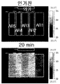
- FIG. 3 illustrates a state in which five heat generating units are connected in series according to another exemplary embodiment of the present invention.
- FIG. 4 is a photograph showing a heat generation state before voltage application and 20 minutes after voltage application to the heating element shown in FIG. 3.
- Figure 5 illustrates the configuration of a heating element according to another embodiment of the present invention.
- FIG. 6 shows an example in which the heat generating means is short-circuited in the heat generating unit of the heating element according to another exemplary embodiment of the present invention.
- FIG. 7 is a view showing a relationship between the length (W) of the bus bar and the elevated temperature according to the first embodiment of the present invention.
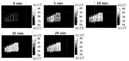
- FIG. 8 illustrates a state in which six heat generating units are connected in series according to another exemplary embodiment of the present invention.
- FIG. 9 is a photograph showing a heat generation state before voltage application and 20 minutes after voltage application to the heating element illustrated in FIG. 8.
- FIG. 10 is a diagram showing a relationship between an interval L between bus bars and a temperature increase temperature according to Embodiment 1 of the present invention.
- FIG. 10 is a diagram showing a relationship between an interval L between bus bars and a temperature increase temperature according to Embodiment 1 of the present invention.
- the heating element according to the present invention includes two or more heat generating units including two bus bars and conductive heating means electrically connected to the two bus bars, and the heat generating elements are connected to the bus bars of the heat generating units in series.
- the power per unit area of each of the heat generating units within is characterized in that the relationship decreases as the length of the bus bar increases.
- the power per unit area of each heat generating unit in the heating element satisfies the relationship that decreases as the length of the bus bar increases, but the power per unit area of each heat generating unit is equal to two powers in each heat generating unit. There may be no specific correlation with the spacing between bus bars.
- the power per unit area of each of the heat generating units decreases as the length of the bus bars increases. Can satisfy the relationship.
- the power per unit area of each heat generating unit may not have a specific correlation with the distance between two bus bars in each heat generating unit.
- the conductive heating means is electrically connected to the bus bar, when the voltage is applied to the bus bar means a means that can generate heat by its own resistance and thermal conductivity.
- a conductive material made of a plane or a line may be used.
- the heat generating means may be made of a transparent conductive material such as ITO, ZnO, or a thin film of an opaque conductive material.
- the heat generating means is linear, it may be made of a transparent or opaque conductive material. In the present invention, when the heat generating means is linear, even when the material is an opaque material such as metal, it is possible to configure the line width and the uniformity of the pattern as described below so as not to obstruct the visual field.
- the heat generating means is referred to as a conductive heat generating surface, and in the case of a linear shape, as a conductive heating wire.
- the extent of temperature rise is determined by power per unit area.
- the power per unit area of region A and region B of FIG. 1 may be calculated as follows.
- V 2 / (Rs ⁇ La / Wa) / (La ⁇ Wa) V 2 / (Rs ⁇ La 2 )
- V 2 / (Rs ⁇ Lb / Wb) / (Lb ⁇ Wb) V 2 / (Rs ⁇ Lb 2 )
- V is the voltage applied by the power supply unit
- Rs is the sheet resistance (Ohm / square) of the heating element.
- the power per unit area of region A and region B of FIG. 2 may be calculated as follows.
- V is the voltage applied by the power supply unit
- Rs is the sheet resistance (Ohm / square) of the heating element
- i is a constant calculated as follows.
- the parallel connection method should control the distance between the bus bars (La, Lb).
- the parallel connection method By using the parallel connection method, there is an advantage in that heat can be generated simultaneously by connecting a plurality of heat generating units.
- the present invention by connecting two or more heat generating units in series, it is possible to easily adjust the amount of heat generated for each part by adjusting the lengths Wa and Wb of the bus bars.
- the spacing between each heat generating unit may be 2 cm or less, preferably 0.5 cm or less. When the distance between the heat generating units exceeds 2cm, a problem may occur in which heat generation of the space between the heat generating units is lowered.
- the heat generation amount of the heat generating unit may be 700W or less per m 2 , may be 300W or less, may be 100W or more.
- the heating element according to the present invention has excellent heat generating performance even at low voltage, for example, 30V or less or 20V or less, and thus may be usefully used in automobiles and the like.
- the lengths of the bus bars of at least two heat generating units of the heat generating units may be different from each other.
- the calorific values of at least two heat generating units of the heat generating units may be different from each other.
- the amount of heat generated in each of the heat generating units may be adjusted by adjusting the length of the bus bar of each of the heat generating units.
- the amount of heat generated between the heat generating units may be adjusted differently, or all of them may be adjusted within the same range.
- the sheet resistance or transmittance deviation between the heat generating units may be adjusted to be within 20%, 10%, or 5%.
- the heat generation amount in each of the heat generating units can be made the same by making the lengths of the bus bars the same. Therefore, even when the object to which the heating element according to the present invention is applied must be configured in a specific shape such as a side glass of a car, the length of the bus bar is the same, so that the heat resistance of each part is uniform, and the sheet resistance of the conductive heating surface is uniform.
- the pattern density of the conductive heating line may be uniform. When the pattern density of the conductive heating line is made uniform, the conductive heating line pattern may be prevented from covering the field of view.
- the temperature deviation in the heat generating unit is within 20%, or within 10%
- the sheet resistance or transmittance deviation between the heat generating units can be adjusted to be within 20%, within 10%, or within 5%.
- the conductive heating line is configured by making the difference in the pattern density between the heating units smaller. You can make the pattern inconspicuous.
- the conductive heating line may be a straight line, but various modifications such as curved lines, wavy lines, and zigzag lines are possible.
- the entire pattern of the conductive heating wires included in each of the two or more heating units may be determined at once in the form of a pattern to be described later.
- the conductive heating line may be provided as a stripe, a rhombus, a square grid, a circle, a wave pattern, a grid, a two-dimensional grid, or the like, and the light emitted from a certain light source is not limited thereto. It is desirable to be designed so that the optical properties are not impaired by diffraction and interference. That is, in order to minimize the regularity of the pattern, a pattern consisting of spacing and sine wave and lattice structure spacing and line thickness irregularly may be used. If necessary, the shape of the conductive heating line pattern may be a combination of two or more patterns.
- the pattern of the conductive heating line may include an irregular pattern.
- the irregular pattern may include a pattern having a standard deviation ratio (distance distribution ratio) of 2% or more with respect to an average value of distances between adjacent straight points of the conductive heating line when a straight line intersecting the conductive heating line is drawn. have.
- a standard deviation ratio distance distribution ratio
- the straight line crossing the conductive heating line may be a line having the smallest standard deviation of the distance between the straight line and the adjacent intersection points of the conductive heating line.
- the straight line intersecting the conductive heating line may be a straight line extending in a direction perpendicular to the tangent of the conductive heating line.
- a straight line crossing the conductive heating line may have 80 or more intersection points with the conductive heating line.
- the ratio of the standard deviation (distance distribution ratio) to the average value of the distance between the straight line crossing the conductive heating line and the adjacent intersection points of the conductive heating line may be 2% or more, 10% or more, and 20% or more.
- At least a part of the surface of the transparent substrate provided with the heating line pattern may be provided in the conductive heating line pattern of another form.
- the irregular pattern includes a pattern in which distributions are continuously closed figures, and a ratio of the standard deviation (area distribution ratio) to the average value of the areas of the closed figures is 2% or more. It may include.
- the ratio of the standard deviation (area distribution ratio) to the average value of the areas of the closed figures may be 2% or more, 10% or more, and 20% or more.
- At least a part of the surface of the transparent substrate provided with the heating line pattern having a ratio of the standard deviation (area distribution ratio) to the average value of the area of the closed figures is 2% or more may be provided in the conductive heating line pattern of another form.
- the patterns are completely irregular, there may be a difference between small and dense lines in the distribution of the lines. Such a distribution of lines may cause a noticeable problem no matter how thin the line width is.
- regularity and irregularity can be appropriately balanced when forming a heating line.
- the base unit may be determined so that the heating line does not stand out or the local heating occurs, and the heating line may be formed in an irregular pattern within the base unit.
- the visual distribution can be compensated by preventing the distribution of lines from being concentrated at any one point.
- the irregular pattern may include a conductive heating line pattern having a boundary form of figures constituting the Voronoi diagram.
- the conductive heating line pattern in the form of a boundary line of figures constituting the Voronoi diagram, it is possible to prevent moiré and minimize side effects caused by diffraction and interference of light.
- the Voronoi diagram if you place the points of the Voronoi diagram generator in the area you want to fill, each point fills the area closest to the point compared to the other points. Pattern in a way. For example, suppose that a large discount store in the country is displayed as a dot and consumers go to the nearest large discount store. That is, when the space is filled with a regular hexagon and each point of the regular hexagon is selected as a Voronoi generator, the honeycomb structure may be the conductive heating line pattern.
- the conductive heating line pattern is formed using the Voronoi diagram generator, a complex pattern shape that can minimize side effects due to diffraction and interference of light can be easily determined.
- a pattern derived from the generator can be used by regularly or irregularly positioning the Voronoi diagram generator.
- the conductive heating line pattern is formed in the shape of the boundary line of the figures constituting the Voronoi diagram, in order to solve the problem of visual perception as described above, regularity and irregularity can be appropriately balanced when generating the Voronoi diagram generator. . For example, after designating an area of a certain size as a basic unit for the area to be patterned, a point is generated so that the distribution of points in the basic unit is irregular, and then a Voronoi pattern may be manufactured. Using this method, the visual distribution can be compensated by preventing the distribution of lines from being concentrated at any one point.
- the number per unit area of the Voronoi diagram generator may be adjusted to consider the visibility of the heating line or to match the heating density required by the display device.
- the unit area may be 5 cm 2 or less, and 1 cm 2 or less.
- the number per unit area of the Voronoi diagram generator may be selected from 25 to 2,500 pieces / cm 2 , and may be selected from 100 to 2,000 pieces / cm 2 .
- At least one of the figures constituting the pattern within the unit area may have a shape different from the remaining figures.
- the irregular pattern may include a conductive heating line pattern in the form of a boundary line of figures consisting of at least one triangle constituting the Delaunay pattern.
- the conductive heating line pattern has a boundary line shape of triangles constituting the Delaunay pattern, or a boundary line shape of figures consisting of at least two triangles constituting the Delaunay pattern, or a combination thereof.
- Delaunay pattern is a pattern that is called the Delaunay pattern generator in the area to fill the pattern and connects three surrounding points to form a triangle, but includes all the vertices of the triangle.
- a pattern is formed by drawing a triangle so that no other point exists in the circle.
- Delaunay triangulation and circulation may be repeated based on the Delaunay pattern generator.
- the Delaunay triangulation can be performed in such a way as to avoid the skinny triangle by maximizing the minimum angle of all angles of the triangle.
- the concept of the Delaunay pattern was proposed in 1934 by Boris Delaunay.
- the pattern in the form of a boundary line of figures consisting of at least one triangle constituting the Delaunay pattern may use a pattern derived from the generator by regularly or irregularly positioning the location of the Delaunay pattern generator.
- the conductive heating line pattern is formed using the Delaunay pattern generator, there is an advantage that the complex pattern shape can be easily determined.
- the conductive heating line pattern is formed in the form of a boundary line of figures consisting of at least one triangle constituting the Delaunay pattern, in order to solve the problem of visual perception as described above, regularity and irregularity when generating the Delaunay pattern generator Can be appropriately harmonized.
- the number per unit area of the Delaunay pattern generator may be adjusted. At this time, when adjusting the number per unit area of the Delaunay pattern generator, the unit area may be 5 cm 2 or less, and may be 1 cm 2 or less. The number per unit area of the Delaunay pattern generator may be selected from 25 to 2,500 pieces / cm 2 , and may be selected from 100 to 2,000 pieces / cm 2 .
- At least one of the figures constituting the pattern within the unit area may have a shape different from the remaining figures.
- the opening ratio of the conductive heating line pattern may be constant in the unit area.
- the heating element may have a transmittance deviation of 5% or less for any circle having a diameter of 20 cm. In this case, the heating element can prevent local heating. In addition, the heating element may be within 20% of the standard deviation of the surface temperature of the transparent substrate after the heating.
- the conductive heating line may be disposed so that a temperature deviation occurs in the heating element.
- the conductive heating line pattern may be formed such that a pattern area made of asymmetrical figures is 10% or more with respect to the entire pattern area.
- at least one of the lines connecting the center point of one figure constituting the Voronoi diagram with the center point of the adjacent figure forming the boundary with the figure is 10% of the total conductive heating line pattern area. It can be formed so that it may become abnormal.
- at least one side of the figure consisting of at least one triangle constituting the Delaunay pattern is formed so that the pattern area consisting of figures different in length from the other side is 10% or more with respect to the area where the pattern of the entire conductive heating line is formed. Can be.
- a large area pattern may be manufactured by using a method of designing a pattern in a limited area and then repeatedly connecting the limited area.
- the repetitive patterns may be connected to each other by fixing the positions of the points of each quadrangle.
- the limited area may have an area of 1 cm 2 or more, and an area of 10 cm 2 or more in order to minimize the moiré phenomenon and the diffraction and interference of light by repetition.
- the line width is thin on a transparent substrate and precise conductive heating line pattern Can be formed.
- a Voronoi diagram generator or a Delaunay pattern generator can be used, thereby making it possible to easily determine a complex pattern shape.
- the Voronoi diagram generator and the Delaunay pattern generator mean points arranged to form the Voronoi diagram and the Delaunay pattern as described above.
- the scope of the present invention is not limited thereto, and other methods may be used when determining the desired pattern form.
- the printing method may be performed by transferring a paste containing a conductive heating wire material onto a transparent substrate in the form of a desired pattern and then baking the paste.
- the transfer method is not particularly limited, and the pattern may be formed on a pattern transfer medium such as an intaglio or a screen, and a desired pattern may be transferred onto the transparent substrate using the pattern.
- the method of forming a pattern shape on the pattern transfer medium may use a method known in the art.
- the printing method is not particularly limited, and printing methods such as offset printing, screen printing, and gravure printing may be used.
- Offset printing may be performed by filling a paste on a patterned intaglio and then performing a primary transfer with a silicone rubber called a blanket, and then performing a secondary transfer by bringing the blanket and the transparent substrate into close contact with each other.
- Screen printing may be performed by placing the paste on a patterned screen and then placing the paste on the substrate directly through the screen where the space is empty while pushing the squeegee.
- Gravure printing may be performed by winding a blanket engraved with a pattern on a roll, filling a paste into a pattern, and then transferring the transparent substrate.
- the above schemes as well as the schemes may be used in combination. It is also possible to use a printing method known to those skilled in the art.
- the intaglio may be manufactured by precisely etching a glass having a desired conductive heating line pattern engraved thereon, or may be metal or DLC (Diamond-like Carbon) coating on the glass surface for durability.
- the intaglio may be produced by etching a metal plate.
- an offset printing method may be used to implement a more precise conductive heating line pattern.
- a doctor blade is used as a first step to fill a pattern of intaglio, and then the blanket is rotated to first transfer, and as a second step, the blanket is rotated to make a surface of the transparent substrate.
- the photolithography step is not limited to the printing method described above.
- a conductive heating line pattern material layer is formed on the entire surface of the transparent substrate, a photoresist layer is formed thereon, the photoresist layer is patterned by a selective exposure and development process, and then the patterned photoresist is formed.
- the layer may be used as a mask to etch the conductive heating pattern material layer to pattern the conductive heating line and to remove the photoresist layer.
- the conductive heating line pattern material layer may be formed by laminating a metal thin film such as copper, aluminum, or silver using an adhesive layer on a transparent substrate.
- the conductive heating line pattern material layer may be a metal layer formed on a transparent substrate by sputtering or physical vapor deposition.
- the conductive heating wire pattern material layer may be formed of a multi-layered structure of a metal such as Mo, Ni, Cr, Ti, which has good electrical conductivity, such as copper, aluminum, and silver, and is well adhered to the substrate. .
- the thickness of the metal thin film may be 20 micrometers or less, and may be 10 micrometers or less.
- the photoresist layer may be formed using a printing process instead of the photolithography process in the photolithography process.
- the present invention may also utilize a photography method.
- the photosensitive material may be patterned by selective exposure and development processes. More detailed examples are as follows.
- a negative photosensitive material is apply
- a polymer film such as PET or acetyl celluloid may be used as the substrate.
- the polymer film material coated with the photosensitive material will be referred to herein as a film.
- the negative photosensitive material may be generally composed of silver halide mixed with some AgI in AgBr which is very sensitive to light and regularly reacts with light. Since the image processed by photographing a general negative photosensitive material is negative in contrast with a subject, contrast, photographing may be performed using a mask having a pattern shape to be formed, preferably an irregular pattern shape.
- Plating may be further performed to increase the conductivity of the heating line pattern formed by using photolithography and a photolithography process.
- the plating may use an electroless plating method, and copper or nickel may be used as the plating material, and nickel plating may be performed thereon after copper plating, but the scope of the present invention is limited only to these examples. It is not.
- the present invention may also use a method using a mask.
- a mask having a heating line pattern shape may be positioned near the substrate, and then patterned using a method of depositing the heating line pattern material on the substrate.
- the deposition method may be a thermal vapor deposition method by heat or electron beam and a physical vapor deposition (PVD) method such as sputter, or a chemical vapor deposition (CVD) method using an organometallic material. It can also be used.
- PVD physical vapor deposition
- CVD chemical vapor deposition
- the heating element may be provided on a transparent substrate.
- the transparent substrate is not particularly limited, but light transmittance may be 50% or more, and 75% or more.
- glass may be used as the transparent substrate, or a plastic substrate or a plastic film may be used.
- the glass may be bonded to at least one surface of the substrate.
- the glass or plastic substrate may be bonded to the surface on which the conductive heating line pattern of the transparent substrate is formed.
- the plastic substrate or film may be a material known in the art, for example, polyethylene terephthalate (PET), polyvinylbutyral (PVB), polyethylene naphthalate (PEN), polyethersulfon (PES), polycarbonate (PC), acetyl celluloid and
- PET polyethylene terephthalate
- PVB polyvinylbutyral
- PEN polyethylene naphthalate
- PS polyethersulfon
- PC polycarbonate
- acetyl celluloid acetyl celluloid
- the film may have the same visible light transmittance of 80% or more.
- the plastic film may have a thickness of 12.5 to 500 micrometers and 50 to 250 micrometers.
- a metal having excellent thermal conductivity may be used as a material of the conductive heating wire.
- the specific resistance value of the conductive heating wire material may have a value of 1 microOhm cm or more and 200 microOhm cm or less.
- the conductive heating wire material copper, silver, carbon nanotubes (CNT), or the like may be used, and silver is most preferred.
- the conductive heating wire material may be used in the form of particles. In the present invention, copper particles coated with silver may also be used as the conductive heating wire material.
- the paste when the conductive heating wire is manufactured using a printing process using a paste, the paste may further include an organic binder in addition to the conductive heating wire material described above to facilitate the printing process.
- the organic binder may have a volatilization property in a sintering process.
- the organic binder may be a polyacrylic resin, a polyurethane resin, a polyester resin, a polyolefin resin, a polycarbonate resin, a cellulose resin, a polyimide resin, a polyethylene naphthalate resin, a modified epoxy, and the like. It is not limited only to.
- the paste may further include glass frit.
- the glass frit may be selected from commercially available products, but it is preferable to use an environmentally friendly glass frit free of lead.
- the glass frit used should have an average aperture of 2 micrometers or less and a maximum aperture of 50 micrometers or less.
- a solvent may be further added to the paste.
- the solvent may include butyl carbitol acetate, carbitol acetate, cyclohexanon, cellosolve acetate, terpineol, and the like. The scope of the present invention is not limited.
- the weight ratio of each component is 50 to 90% by weight of the conductive heating wire material, 1 to 20% by weight of the organic binder, glass frit 0.1 ⁇ 10% by weight and the solvent 1 to 20% by weight is preferable.
- a heating line having conductivity is formed when the paste is printed and then fired.
- the firing temperature is not particularly limited, but may be 500 to 800 ° C, and may be 600 to 700 ° C.
- the transparent substrate forming the heating wire pattern is glass
- the glass may be molded to suit the intended use, such as for building or automobile, in the firing step if necessary.
- the paste may be calcined in the step of forming an automotive glass into a curved surface.
- the baking may be performed at a relatively low temperature. For example, it can be carried out at 50 to 350 °C.
- the line width of the conductive heating wire may be 100 micrometers or less, 30 micrometers or less, 25 micrometers or less, 10 micrometers or less, even more preferably 7 micrometers or less, and 5 micrometers or less. have.
- the line width of the conductive heating wire may be 0.1 micrometer or more and 0.2 micrometer or more.
- the line spacing of the conductive heating wire may be 30 mm or less, 0.1 micrometers to 1 mm, 0.2 micrometers to 600 micrometers, or less, and 250 micrometers or less.
- the height of the heating wire may be 100 micrometers or less, 10 micrometers or less, or 2 micrometers or less.
- the line width and line height of the heating wire can be made uniform by the aforementioned methods.
- the uniformity of the heating line may be within the range of ⁇ 3 micrometers in the case of the line width, and may be within the range of ⁇ 1 micrometer in the case of the line height.
- the conductive heating surface may be formed of a transparent conductive material.
- the transparent conductive material include ITO and ZnO-based transparent conductive oxides.
- the transparent conductive oxide may be formed by sputtering, a sol-gel method, or a vapor deposition method, and has a thickness of 10 to 1,000 nm.
- the opaque conductive material may be formed by coating a thickness of 1 ⁇ 100nm.
- the opaque conductive material may be Ag, Au, Cu, Al, carbon nanotubes (carbon nanotube).
- the heating element according to the present invention may further include a power supply unit connected to the bus bar.
- the bus bar and the power supply unit may be formed using a method known in the art.
- the bus bar may be formed simultaneously with the formation of the conductive heating means or may be formed using the same or different printing method after the conductive heating means is formed.
- a bus bar may be formed through screen printing. In this case, the thickness of the bus bar may be 1 to 100 micrometers, and may be 10 to 50 micrometers.
- connection between the bus bar and the power supply unit can be made through physical contact with a structure having good soldering and conductive heat generation.
- a black pattern may be formed.
- the black pattern may be printed using a paste containing cobalt oxide.
- the printing method is suitable for screen printing, the thickness is 10 ⁇ 100 micrometers is appropriate.
- the conductive heating means and the bus bar may be formed before or after the black pattern is formed, respectively.
- the heating element according to the present invention may include an additional transparent substrate provided on the side provided with the conductive heating means of the transparent substrate.
- an additional transparent substrate provided on the side provided with the conductive heating means of the transparent substrate.
- glass, a plastic substrate or a film may be used as described above.
- the bonding film may be sandwiched between the conductive heating means and the additional transparent substrate when the additional transparent substrate is bonded. Temperature and pressure can be controlled during the bonding process.
- any material having adhesion and becoming transparent after bonding can be used.
- PVB film, EVA film, PU film and the like can be used, but is not limited to these examples.
- the bonding film is not particularly limited, but may have a thickness of 100 to 800 micrometers.
- the adhesive film is inserted between the transparent substrate on which the conductive heating means is formed and the additional transparent substrate, and put it in a vacuum bag to increase the temperature under reduced pressure, or raise the temperature using a hot roll,
- the primary junction is achieved by removing the air.
- the pressure, temperature and time is different depending on the type of adhesive film, but the pressure is usually 300 ⁇ 700 torr, it can gradually raise the temperature from room temperature to 100 °C. At this time, the time may be usually within 1 hour.
- the pre-bonded laminate is subjected to the secondary bonding process by the autoclaving process of applying pressure in the autoclave and raising the temperature. Secondary bonding may vary depending on the type of adhesive film, but may be slowly cooled after 1 hour to 3 hours, or about 2 hours at a pressure of 140 bar or more and a temperature of about 130 to 150 ° C.
- a method of bonding in one step using a vacuum laminator device may be used.
- the temperature can be gradually reduced to 80 to 150 ° C. while being cooled slowly, to 100 ° C. under reduced pressure ( ⁇ 5 mbar), and then pressurized ( ⁇ 1,000 mbar) to join.
- the heating element according to the present invention may have a shape forming a curved surface.
- the opening ratio of the conductive heating line pattern when the heating means is linear, the opening ratio of the conductive heating line pattern, that is, the ratio of the region not covered by the pattern may be 70% or more.
- the heating element according to the present invention has an excellent heat generation property that can increase the temperature while maintaining an opening ratio of 70% or more while maintaining a temperature deviation of 10% or less within 5 minutes after the heating operation.
- the heating element according to the present invention may be connected to a power source for heat generation, in which the calorific value may be 700 W or less per m 2 , 300 W or less, and 100 W or more.
- the heating element according to the present invention has excellent heat generating performance even at low voltage, for example, 30V or less, or 20V or less, and thus may be usefully used in automobiles and the like.
- the resistance in the heating element may be 5 ohms / square or less, 1 ohms / square or less, or 0.5 ohms / square or less.
- the heating element according to the present invention can be applied to glass or display devices used in various transportation means such as automobiles, ships, railways, high speed trains, airplanes, or houses or other buildings.
- the heating element according to the present invention not only has excellent heat generating characteristics even at low voltage, but also minimizes side effects due to diffraction and interference of the light source after sunset, and can be formed inconspicuously with the line width as described above. Unlike technology, it can also be applied to the windshield of vehicles such as automobiles.
- heating element according to the present invention may be applied to a display device.
- 3D TVs based on liquid crystal have been implemented to realize 3D images by binocular disparity.
- the most common way to generate binocular parallax is to use glasses with shutters synchronized with the playback frequency of the liquid crystal display.
- the left and right eye images should be alternately displayed on the liquid crystal display.
- the left and right eye images may overlap. Due to the overlapping phenomenon, the viewer may feel an unnatural 3D effect, and thus dizziness may occur.
- the movement of the liquid crystal used in the liquid crystal display may change in speed depending on the ambient temperature. That is, when driving a liquid crystal display at a low temperature, the liquid crystal change rate becomes slow, and when driving a liquid crystal display at a high temperature, the liquid crystal change rate becomes faster.
- heat generated in the backlight unit may affect the liquid crystal speed.
- the heat generated from the backlight unit may increase the temperature around the backlight unit, resulting in a deviation of the liquid crystal driving speed, thereby resulting in a 3D image.
- the non-ideal implementation of can be deepened.
- the present invention by applying the above-described heating element to a display device, especially a liquid crystal display, not only can excellent display characteristics be achieved during initial driving at low temperature, but also when the light source such as an edge type light source is located on the side surface of the light source. Even when a temperature deviation occurs in the entire display screen depending on the position, it is possible to provide uniform display characteristics throughout the display screen. In particular, it is possible to minimize the 3D image distortion generated in the 3D display device by increasing the ambient temperature of the liquid crystal by providing a heat generating function to the liquid crystal display, thereby realizing a high liquid crystal change rate.
- the display device may include a display panel and a heating element provided on at least one side of the display panel.
- the display device includes an edge type light source
- the heat generating unit disposed close to the light source among the heat generating elements relatively lengthens the bus bar
- the heat generating unit disposed far from the light source decreases the length of the bus bar relatively short.
- the temperature deviation according to the light source can be compensated for. As described above, while the local heating is performed to compensate for the temperature deviation, the visibility of the surface of the conductive heating surface or the pattern density of the conductive heating line is uniform in the entire display screen of the display device, thereby ensuring visibility.
- the display panel may be provided on the separate transparent substrate, or may be provided on one component of the display panel or other components of the display device.
- the display panel may include two substrates and a liquid crystal cell including a liquid crystal material encapsulated between the substrates, and the heating element may be provided inside or outside at least one of the substrates.
- the display panel may include polarizing plates provided on both sides of the liquid crystal cell, and the heating element may be provided on a phase difference compensation film provided between at least one of the liquid crystal cell and the polarizing plate.
- the polarizing plate includes a polarizing film and at least one protective film
- the heating element may be provided on at least one side of the protective film.
- the display device may include a backlight unit.
- the backlight unit may include a direct type light source or an edge type light source.
- the backlight unit may further include a light guide plate.
- the light source may be disposed at one or more edge portions of the light guide plate.
- the light source may be disposed only on one side of the light guide plate, and may be disposed at two to four edge portions.
- the heating element may be provided on the front side or the rear side of the backlight unit. In addition, the heating element may be provided directly on the front or rear of the light guide plate.
- the heating element When the heating element is provided on a separate transparent substrate, the heating element may be provided on the front or rear of the display panel, may be provided between the liquid crystal cell and at least one polarizing plate, between the display panel and the light source, the light guide plate It may be provided in the front or rear of the.
- the pattern of the conductive heating line may include an irregular pattern.
- the moire phenomenon of the display device can be prevented by an irregular pattern.
- the display device may include the heating element, and adjust the configuration of the heating element to prevent excessive heat generation and power consumption in the electronic product.
- the configuration of the heat generating film included in the display device according to the present invention may be adjusted such that power consumption, voltage, and heat generation amount are within a range as described below.
- the heating element included in the display device according to the present invention may use power consumption of 100 W or less when connected to a power source. If the power consumption exceeds 100W, 3D image distortion due to temperature rise is improved, but it may affect the power saving performance of the product due to the increased power consumption.
- the heating element of the display device according to the present invention may use a voltage of 20V or less, and a voltage of 12V or less. When the voltage exceeds 20 V, it is preferable to use a voltage as low as possible because there is a risk of electric shock due to a short circuit.
- Surface temperature of the display device using the heating element according to the invention is characterized in that it is controlled at 40 °C or less. Increasing the temperature to more than 40 °C can minimize the 3D image distortion, there is a problem that the power consumption may exceed 100W.
- the heating value may be 400 W or less per m 2 , or 200 W or less.
- the display device using the heating element according to the present invention may include the heating element described above, and may be provided with a control device for controlling the surface temperature in order to implement power saving products currently pursued by electronic products.
- the control device may control the surface temperature of the display device to 40 ° C. or less.
- the control device may have a function of generating heat only for a predetermined time by using a timer, and may have a function of attaching a temperature sensor to a surface of the display device to increase the temperature to a proper temperature and cut off power.
- the control device may perform a function for minimizing power consumption of the display device.
- the conductive heat generating means of the heat generating unit when at least one bus bar of at least one of the heat generating units is disposed diagonally, the conductive heat generating means of the heat generating unit includes a portion in which the current is shorted, whereby the current is shortest between the bus bars. It is concentrated in the diagonal direction which is a distance, and can prevent local heat generation.
- the current in order to equally adjust the bus bar length between the heat generating units, for example, when the bus bars are arranged diagonally as shown in FIG. 5, the current is a diagonal line in which the current is the shortest distance between the bus bars. Direction, so that local heating may occur around the diagonal of the shortest distance.
- the conductive heating means may be short-circuited at intervals of 0.1 to 20 mm along the bus bar in the area where the bus bar is diagonally disposed.
- An example of shorting the conductive heating means is illustrated in FIG. 6.
- the heat generating unit was disposed on the transparent substrate in the structure as shown in FIG. 3. At this time, the interval between each heat generating unit is 1mm and the length (W) of the bus bar was configured as shown in Table 1 below.
- the sheet resistance of the conductive heating wire provided between the bus bars of each heating unit was 0.33 ohm / square, the voltage / current was 21.6V and 3.8A, the power was 82.1W, and the length L between the bus bars was 70cm.
- Table 1 show average temperatures measured before and after voltage application of the heating element manufactured in Example 1, 20 minutes after voltage application.
- the relationship between the length (W) of the bus bar and the elevated temperature is shown in FIG. 7.
- the heat generating unit was disposed only on the rectangle indicated by the dotted line in the structure as shown in FIG. At this time, the interval between each heat generating unit was 1mm and the length (W) of the bus bar and the distance (L) between the bus bar was configured as shown in Table 2.
- the sheet resistance of the conductive heating wire provided between the bus bars of each heating unit was 0.33 ohm / square, the voltage / current was 14V and 2.4A, respectively, and the power was 33.6W.
- Table 2 show the average temperatures measured before the voltage application and 20 minutes after the voltage application of the heating element manufactured in Example 2.
- FIG. 10 the relationship between the bus bar interval L and the elevated temperature is shown in FIG. 10.
- the power per unit area in one heat generating unit can be fixed by the length of the bus bar, thereby adjusting the length of the bus bar for each heat generating unit.
- the calorific value of each part can be easily adjusted, thereby providing a heating element having no difference in permeability or sheet resistance between the heating units.
Landscapes
- Engineering & Computer Science (AREA)
- Chemical & Material Sciences (AREA)
- Ceramic Engineering (AREA)
- Manufacturing & Machinery (AREA)
- Surface Heating Bodies (AREA)
- Resistance Heating (AREA)
Abstract
La présente invention porte sur un élément chauffant, qui comprend au moins deux unités de chauffage comprenant deux barres omnibus et un moyen de chauffage électroconducteur connecté électriquement aux deux barres omnibus, et dans lequel les barres omnibus des unités de chauffage sont connectés entre elles en série ; et dans lequel il y a une relation par laquelle la puissance par surface unitaire de chacune des unités de chauffage dans l'élément chauffant diminue lorsque la longueur des barres omnibus augmente. La présente invention porte également sur un procédé de production pour l'élément chauffant.
Priority Applications (3)
| Application Number | Priority Date | Filing Date | Title |
|---|---|---|---|
| EP12734625.2A EP2665336A4 (fr) | 2011-01-13 | 2012-01-13 | Élément chauffant et procédé de production pour celui-ci |
| CN2012800029969A CN103141157A (zh) | 2011-01-13 | 2012-01-13 | 加热元件及其制造方法 |
| US13/820,446 US9029735B2 (en) | 2011-01-13 | 2012-01-13 | Heating element and a production method thereof |
Applications Claiming Priority (2)
| Application Number | Priority Date | Filing Date | Title |
|---|---|---|---|
| KR10-2011-0003475 | 2011-01-13 | ||
| KR20110003475 | 2011-01-13 |
Publications (2)
| Publication Number | Publication Date |
|---|---|
| WO2012096540A2 true WO2012096540A2 (fr) | 2012-07-19 |
| WO2012096540A3 WO2012096540A3 (fr) | 2012-11-15 |
Family
ID=46507594
Family Applications (1)
| Application Number | Title | Priority Date | Filing Date |
|---|---|---|---|
| PCT/KR2012/000323 Ceased WO2012096540A2 (fr) | 2011-01-13 | 2012-01-13 | Élément chauffant et procédé de production pour celui-ci |
Country Status (5)
| Country | Link |
|---|---|
| US (1) | US9029735B2 (fr) |
| EP (1) | EP2665336A4 (fr) |
| KR (1) | KR20120090791A (fr) |
| CN (1) | CN103141157A (fr) |
| WO (1) | WO2012096540A2 (fr) |
Cited By (2)
| Publication number | Priority date | Publication date | Assignee | Title |
|---|---|---|---|---|
| WO2014129845A1 (fr) * | 2013-02-22 | 2014-08-28 | 주식회사 엘지화학 | Élément chauffant et son procédé de fabrication |
| EP2631709B1 (fr) * | 2010-10-22 | 2020-08-19 | LG Chem, Ltd. | Dispositif d'affichage comprenant un motif conducteur |
Families Citing this family (18)
| Publication number | Priority date | Publication date | Assignee | Title |
|---|---|---|---|---|
| US9247587B2 (en) * | 2010-09-14 | 2016-01-26 | Lg Chem, Ltd. | Heating element and a manufacturing method thereof |
| MX374232B (es) * | 2012-08-01 | 2025-03-05 | Saint Gobain | Panel de acristalamiento con medios de conexion electrica. |
| CN106255627A (zh) * | 2014-04-28 | 2016-12-21 | 旭硝子株式会社 | 电加热窗用板状体 |
| KR101865441B1 (ko) * | 2014-09-29 | 2018-06-07 | 주식회사 엘지화학 | 발열체 및 이의 제조방법 |
| EP4120796B1 (fr) * | 2015-01-06 | 2026-04-15 | Battelle Memorial Institute | Répartition uniforme de la chaleur dans les dispositifs de chauffage à résistance de dégivrage et d'antigivrage |
| US20160347028A1 (en) * | 2015-05-26 | 2016-12-01 | Asahi Glass Company, Limited | Stacked plate for window and method of manufacturing stacked plate for window |
| US9668301B2 (en) * | 2015-07-03 | 2017-05-30 | Ndt Engineering & Aerospace Co., Ltd. | Wet-use plane heater using PTC constant heater-ink polymer |
| EP3463946A4 (fr) * | 2016-05-24 | 2020-02-12 | Advanced Materials Enterprises Co., Ltd | Appareil de manipulation de température et son procédé de préparation |
| JP6807186B2 (ja) * | 2016-08-24 | 2021-01-06 | 日本板硝子株式会社 | サイドガラス |
| US20180160481A1 (en) * | 2016-12-02 | 2018-06-07 | Goodrich Corporation | Method to join nano technology carbon allotrope heaters |
| TWI679917B (zh) * | 2018-04-10 | 2019-12-11 | 許詔智 | 電熱裝置 |
| KR102058865B1 (ko) * | 2018-04-12 | 2019-12-24 | (주)아이엠 | 초가속 열소재를 이용한 발열 디바이스 및 이의 제조방법 |
| KR102318135B1 (ko) * | 2018-08-31 | 2021-10-26 | 주식회사 엘지화학 | 발열체 및 이의 제조방법 |
| KR102119652B1 (ko) * | 2018-09-10 | 2020-06-05 | 코리아 오토글라스 주식회사 | 차량 안전유리의 열선 장치 |
| JP2020167047A (ja) * | 2019-03-29 | 2020-10-08 | 日東電工株式会社 | ヒータ |
| KR20210032030A (ko) * | 2019-09-16 | 2021-03-24 | 박상구 | 마름모형 발열체 |
| EP4043255B1 (fr) * | 2021-02-11 | 2024-11-27 | Inalfa Roof Systems Group B.V. | Panneau de toit transparent comportant une unité centrale isolée |
| JP2022184524A (ja) * | 2021-06-01 | 2022-12-13 | 大日本印刷株式会社 | 導電体、合わせ板及びセンサシステム |
Family Cites Families (16)
| Publication number | Priority date | Publication date | Assignee | Title |
|---|---|---|---|---|
| KR890003052B1 (ko) | 1983-03-16 | 1989-08-19 | 칫소 엔지니어링 가부시끼 가이샤 | 띠형 전기발열장치 |
| JP2934046B2 (ja) * | 1991-03-22 | 1999-08-16 | 帝人株式会社 | タイヤウオーマー |
| JPH05181379A (ja) | 1991-12-28 | 1993-07-23 | Rohm Co Ltd | 加熱ヒータおよび加熱ヒータの抵抗値調節方法 |
| JPH06302375A (ja) * | 1993-04-14 | 1994-10-28 | Asahi Glass Co Ltd | 自動車用防曇ガラスの発熱体 |
| US5852284A (en) * | 1997-01-07 | 1998-12-22 | Libbey-Owens-Ford Co. | Insulating glass with capacitively coupled heating system |
| JP2000174486A (ja) * | 1998-12-04 | 2000-06-23 | Sumitomo Rubber Ind Ltd | 透光性電磁波シールドフィルムおよび透光性電磁波シールドパネルの製造方法 |
| KR100316792B1 (ko) * | 1999-05-24 | 2001-12-12 | 윤철진 | 다기능 면상발열체 제조방법 |
| KR100420797B1 (ko) | 2001-11-07 | 2004-03-02 | (주)부풍에너지 | 입자형 탄소발열체로 된 발열장치 |
| KR20030076915A (ko) | 2002-03-23 | 2003-09-29 | 이건국 | 발열 매트 |
| JP4219790B2 (ja) * | 2003-11-14 | 2009-02-04 | 日本板硝子株式会社 | 電熱窓ガラス |
| US7129444B2 (en) | 2004-05-17 | 2006-10-31 | Exatec Llc | High performance defrosters for transparent panels |
| KR20070022332A (ko) * | 2004-05-17 | 2007-02-26 | 엑사테크 엘.엘.씨. | 투명한 패널용 고성능 서리제거장치 |
| JP2007302545A (ja) * | 2006-05-15 | 2007-11-22 | Murakami Corp | 発熱ガラスシステム及び発熱ガラス装置 |
| CN201083912Y (zh) * | 2007-06-26 | 2008-07-09 | 上海广电光电子有限公司 | 具有温度补偿的液晶显示装置 |
| KR20090129927A (ko) * | 2008-06-13 | 2009-12-17 | 주식회사 엘지화학 | 발열체 및 이의 제조방법 |
| CN101983181B (zh) | 2008-06-13 | 2015-10-14 | Lg化学株式会社 | 加热件及其制备方法 |
-
2012
- 2012-01-13 CN CN2012800029969A patent/CN103141157A/zh active Pending
- 2012-01-13 WO PCT/KR2012/000323 patent/WO2012096540A2/fr not_active Ceased
- 2012-01-13 US US13/820,446 patent/US9029735B2/en active Active
- 2012-01-13 EP EP12734625.2A patent/EP2665336A4/fr not_active Withdrawn
- 2012-01-13 KR KR20120004268A patent/KR20120090791A/ko not_active Ceased
Non-Patent Citations (2)
| Title |
|---|
| None |
| See also references of EP2665336A4 |
Cited By (4)
| Publication number | Priority date | Publication date | Assignee | Title |
|---|---|---|---|---|
| EP2631709B1 (fr) * | 2010-10-22 | 2020-08-19 | LG Chem, Ltd. | Dispositif d'affichage comprenant un motif conducteur |
| WO2014129845A1 (fr) * | 2013-02-22 | 2014-08-28 | 주식회사 엘지화학 | Élément chauffant et son procédé de fabrication |
| CN105247953A (zh) * | 2013-02-22 | 2016-01-13 | Lg化学株式会社 | 加热元件及其制造方法 |
| CN105247953B (zh) * | 2013-02-22 | 2018-10-19 | Lg化学株式会社 | 加热元件及其制造方法 |
Also Published As
| Publication number | Publication date |
|---|---|
| EP2665336A4 (fr) | 2018-03-21 |
| EP2665336A2 (fr) | 2013-11-20 |
| US9029735B2 (en) | 2015-05-12 |
| CN103141157A (zh) | 2013-06-05 |
| KR20120090791A (ko) | 2012-08-17 |
| WO2012096540A3 (fr) | 2012-11-15 |
| US20130153559A1 (en) | 2013-06-20 |
Similar Documents
| Publication | Publication Date | Title |
|---|---|---|
| WO2012096540A2 (fr) | Élément chauffant et procédé de production pour celui-ci | |
| WO2014129845A1 (fr) | Élément chauffant et son procédé de fabrication | |
| KR100940436B1 (ko) | 발열체 및 이의 제조방법 | |
| KR100940437B1 (ko) | 발열체 및 이의 제조방법 | |
| WO2016052949A2 (fr) | Élément chauffant et procédé de fabrication de celui-ci | |
| WO2011081456A2 (fr) | Élément de chauffage et son procédé de fabrication | |
| WO2009116786A2 (fr) | Élément chauffant et procédé de fabrication de celui-ci | |
| WO2009116787A2 (fr) | Élément chauffant et procédé de fabrication de celui-ci | |
| WO2013141629A1 (fr) | Élément chauffant et procédé de fabrication de ce dernier | |
| WO2012036459A2 (fr) | Élément chauffant et procédé de fabrication de celui-ci | |
| WO2013162178A1 (fr) | Elément chauffant et procédé pour sa fabrication | |
| US9999099B2 (en) | Heating element and a manufacturing method thereof | |
| WO2012053872A2 (fr) | Dispositif d'affichage comprenant un motif conducteur | |
| WO2015056971A1 (fr) | Élément de chauffage à fenêtre de communication | |
| WO2011122854A2 (fr) | Élément chauffant et son procédé de fabrication | |
| KR101302257B1 (ko) | 발열체 및 이의 제조방법 | |
| WO2010062132A2 (fr) | Corps émetteur de chaleur partielle |
Legal Events
| Date | Code | Title | Description |
|---|---|---|---|
| WWE | Wipo information: entry into national phase |
Ref document number: 201280002996.9 Country of ref document: CN |
|
| 121 | Ep: the epo has been informed by wipo that ep was designated in this application |
Ref document number: 12734625 Country of ref document: EP Kind code of ref document: A2 |
|
| WWE | Wipo information: entry into national phase |
Ref document number: 2012734625 Country of ref document: EP |
|
| WWE | Wipo information: entry into national phase |
Ref document number: 13820446 Country of ref document: US |
|
| NENP | Non-entry into the national phase |
Ref country code: DE |