WO2012098656A1 - 伝送装置、伝送方法および伝送システム - Google Patents
伝送装置、伝送方法および伝送システム Download PDFInfo
- Publication number
- WO2012098656A1 WO2012098656A1 PCT/JP2011/050892 JP2011050892W WO2012098656A1 WO 2012098656 A1 WO2012098656 A1 WO 2012098656A1 JP 2011050892 W JP2011050892 W JP 2011050892W WO 2012098656 A1 WO2012098656 A1 WO 2012098656A1
- Authority
- WO
- WIPO (PCT)
- Prior art keywords
- traffic
- data flow
- transmission
- unit
- rate
- Prior art date
- Legal status (The legal status is an assumption and is not a legal conclusion. Google has not performed a legal analysis and makes no representation as to the accuracy of the status listed.)
- Ceased
Links
Images








Classifications
-
- H—ELECTRICITY
- H04—ELECTRIC COMMUNICATION TECHNIQUE
- H04W—WIRELESS COMMUNICATION NETWORKS
- H04W28/00—Network traffic management; Network resource management
- H04W28/02—Traffic management, e.g. flow control or congestion control
- H04W28/0268—Traffic management, e.g. flow control or congestion control using specific QoS parameters for wireless networks, e.g. QoS class identifier [QCI] or guaranteed bit rate [GBR]
-
- H—ELECTRICITY
- H04—ELECTRIC COMMUNICATION TECHNIQUE
- H04L—TRANSMISSION OF DIGITAL INFORMATION, e.g. TELEGRAPHIC COMMUNICATION
- H04L47/00—Traffic control in data switching networks
- H04L47/10—Flow control; Congestion control
- H04L47/12—Avoiding congestion; Recovering from congestion
- H04L47/125—Avoiding congestion; Recovering from congestion by balancing the load, e.g. traffic engineering
-
- H—ELECTRICITY
- H04—ELECTRIC COMMUNICATION TECHNIQUE
- H04L—TRANSMISSION OF DIGITAL INFORMATION, e.g. TELEGRAPHIC COMMUNICATION
- H04L47/00—Traffic control in data switching networks
- H04L47/10—Flow control; Congestion control
- H04L47/20—Traffic policing
-
- H—ELECTRICITY
- H04—ELECTRIC COMMUNICATION TECHNIQUE
- H04L—TRANSMISSION OF DIGITAL INFORMATION, e.g. TELEGRAPHIC COMMUNICATION
- H04L47/00—Traffic control in data switching networks
- H04L47/10—Flow control; Congestion control
- H04L47/215—Flow control; Congestion control using token-bucket
Definitions
- the present invention relates to a transmission device, a transmission method, and a transmission system.
- the bandwidth guarantee service is used, for example, when performing communication that is highly important and requires high availability.
- the bandwidth guarantee service is used for a VPN (Virtual Private Network) connection of a corporate user, a backhaul connection between a radio base station and a core network in a mobile communication carrier, and the like.
- Metro Ethernet Forum which promotes the use of Ethernet technology in MAN (Metropolitan Area Network), such as providing wide-area Ethernet (registered trademark) services and formulating technical specifications.
- MAN Micropolitan Area Network
- wide-area Ethernet registered trademark
- CIR Commission Information Rate
- Ethernet Virtual Connection Ethernet virtual connection
- EIR Excess Information Rate
- Wireless network links using microwaves as well as wired links such as metal cables and optical fiber cables are used as the connection links for the network of carriers that provide bandwidth guarantee services.
- a high-speed modulation scheme eg, 64QAM, 128QAM, 256QAM, etc.
- Control such as using a high modulation method (for example, BPSK or QPSK) may be performed.
- BPSK or QPSK BPSK or QPSK
- adaptive modulation for example. Due to adaptive modulation, the transmission rate also changes in the case of a radio link.
- link aggregation in which a plurality of communication links are bundled and used as a large-capacity link (for example, Patent Documents 1 to 3 and Non-Patent Documents 3 to 3 below). 5).
- link aggregation there is IEEE 802.3ad as a technical standard when link aggregation is performed for a wired Ethernet link.
- the transmission speeds of all Ethernet links are based on the same assumption, and a sequence number is not assigned to a data packet, and the packet order is guaranteed in a data flow (conversion). For this reason, although a plurality of Ethernet links are bundled, a data packet is transferred using any one Ethernet link for each data flow.
- Metro Ethernet Forum “Introducing the Specifications of the MEF An Overview of MEF 6.1 and MEF 10.1”, Page 35, 36, [online], [24] December t // metroethernetform.
- the above-described conventional technology has a problem that the traffic throughput cannot be improved.
- the transmission speed of each radio link that performs aggregation varies depending on, for example, frequency selective fading or adaptive modulation. If the transmission speed of the wireless link to which the data flow is distributed is lower than the traffic volume of the data flow, even if there is a free bandwidth in other wireless links, a part of the data flow is discarded or delayed, and the throughput is reduced. descend.
- the disclosed transmission apparatus, transmission method, and transmission system are intended to solve the above-described problems and to improve throughput while guaranteeing a bandwidth.
- a transmission apparatus that transmits a data flow using a plurality of radio links acquires a guaranteed rate to be guaranteed in the data flow, and the data flow Is divided into first traffic corresponding to the acquired guaranteed rate and second traffic exceeding the guaranteed rate, and the divided first traffic is prioritized over the second traffic.
- the second traffic is distributed to at least one of the wireless links, and the second traffic is distributed to free bands of the plurality of wireless links.
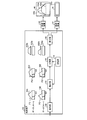
- FIG. 1-1 is a diagram of a configuration example 1 of the transmission apparatus according to the embodiment.
- FIG. 1-2 is a diagram of a configuration example 2 of the transmission apparatus according to the embodiment.
- FIG. 1-3 is a diagram of a configuration example 3 of the transmission apparatus according to the embodiment.
- FIG. 2 is a diagram illustrating a first distribution example of traffic.
- FIG. 3 is a diagram illustrating a second distribution example of traffic.
- FIG. 4 is a diagram illustrating a third distribution example of traffic.
- FIG. 5 is a diagram illustrating a fourth distribution example of traffic.
- FIG. 6A is a diagram illustrating a specific example of the transmission apparatus.
- FIG. 6B is a diagram of an example of transmission apparatuses that face each other.
- FIG. 7A is a diagram of an example 1 of information stored in the storage unit.
- FIG. 7-2 is a diagram of an example 2 of information stored in the storage unit.
- FIG. 7C is a diagram of an example 3 of information stored in the storage unit.
- FIG. 8 is a flowchart showing packet reception processing by the transmission apparatus.
- FIG. 9 is a flowchart illustrating packet transmission processing by the transmission apparatus.
- FIG. 10 is a diagram illustrating an example of a read determination process performed by the transmission apparatus.
- FIG. 11 is a flowchart illustrating an example of read determination processing by the transmission apparatus.
- FIG. 12 is a flowchart (part 1) illustrating an example 1 of excess packet distribution processing.
- FIG. 13 is a flowchart (part 2) illustrating an example 1 of the excess packet sorting process.
- FIG. 14 is a diagram illustrating a first example of distribution by the determination process illustrated in FIGS. 12 and 13.
- FIG. 15 is a diagram illustrating a second example of distribution by the determination process illustrated in FIGS. 12 and 13.
- FIG. 16 is a flowchart illustrating an example 2 of excess packet distribution processing.
- FIG. 17 is a diagram illustrating a first example of distribution by the determination process illustrated in FIG. 16.
- FIG. 18 is a diagram illustrating a distribution example 2 by the determination process illustrated in FIG. 16.
- FIG. 19 is a flowchart illustrating an example 3 of excess packet distribution processing.
- FIG. 20 is a diagram illustrating a first example of a transmission system to which the transmission apparatus is applied.
- FIG. 21 is a diagram illustrating a second example of the transmission system to which the transmission apparatus is applied.
- FIG. 1-1 is a diagram of a configuration example 1 of the transmission apparatus according to the embodiment.
- the transmission apparatus 100 includes a storage unit 110, a dividing unit 120, and a distribution unit 130.
- the transmission apparatus 100 transmits a data flow to the opposite apparatus by link aggregation using a plurality of wireless links.
- the transmission apparatus 100 transmits a data flow by link aggregation using the aggregation links # 1 and # 2.
- Each of the aggregation links # 1 and # 2 is a radio link.
- a data flow is a group of packets identified by, for example, an input link (input port), destination or source MAC address, destination or source IP address, destination or source port number, upper layer type, etc. is there.
- the transfer devices 141 and 142 are transfer devices that transfer the traffic distributed from the transmission device 100 through the aggregation links # 1 and # 2, respectively.
- the transfer apparatuses 141 and 142 acquire and manage the states of the aggregation links # 1 and # 2, respectively.
- the states of the aggregation links # 1 and # 2 are transmission rates that vary depending on, for example, the radio states of the aggregation links # 1 and # 2.
- the transfer apparatuses 141 and 142 acquire parameters such as the guaranteed rate and peak rate of each data flow.
- the transfer devices 141 and 142 identify the data packets of the data flows 1 and 2 for the input packet from the transmission device 100, and transfer traffic from the size of the data packet and the elapsed time from the previous transmission. Monitor volume. Further, when the traffic of the input data flows 1 and 2 exceeds the peak rate, the transfer devices 141 and 142 transmit each traffic while performing traffic shaping.
- the traffic 101 is data flow traffic transmitted by the transmission apparatus 100.
- the horizontal direction indicates time
- the vertical direction indicates the traffic amount (rate).
- the guaranteed rate A1 indicates the guaranteed rate to be guaranteed in the data flow transmitted by the transmission apparatus 100.
- the traffic 101 has a traffic amount exceeding the guaranteed rate A1.
- the storage unit 110 stores the guaranteed rate A1 of the data flow transmitted by the transmission apparatus 100.
- the dividing unit 120 and the allocating unit 130 perform output scheduling of data flow traffic based on the traffic amount of the data flow transmitted by the transmission apparatus 100 and the transmission speeds of the aggregation links # 1 and # 2.
- the information on the respective transmission rates of the aggregation links # 1 and # 2 can be acquired by notification from the transfer apparatuses 141 and 142 or an inquiry from the transmission apparatus 100 to the transfer apparatuses 141 and 142.
- the dividing unit 120 acquires the guaranteed rate A1 stored in the storage unit 110. Then, the dividing unit 120 divides the traffic 101 into guaranteed traffic 101a (first traffic) corresponding to the guaranteed rate A1 and excess traffic 101b (second traffic) exceeding the guaranteed rate A1. The dividing unit 120 outputs the divided guaranteed traffic 101a and excess traffic 101b to the distributing unit 130.
- the distributing unit 130 distributes the guaranteed traffic 101a output from the dividing unit 120 to at least one of the aggregation links # 1 and # 2.
- the distribution unit 130 distributes the guaranteed traffic 101a with priority over the excess traffic 101b.
- the allocating unit 130 distributes the excess traffic 101b output from the dividing unit 120 to the free bands of the aggregation links # 1 and # 2. As described above, the allocating unit 130 divides the excess traffic 101b from the guaranteed traffic 101a and distributes it to the free bandwidths of the aggregation links # 1 and # 2. Thereby, the excess traffic 101b can be transmitted using the free bandwidth of the aggregation links # 1 and # 2, and the throughput can be improved.
- the distributing unit 130 distributes the guaranteed traffic 101a to the aggregation link # 1.
- the distribution unit 130 distributes the excess traffic 101b to the aggregation link # 2. Thereby, the delay and discard of the excess traffic 101b can be avoided, and the throughput can be improved.
- the distribution unit 130 outputs the traffic distributed to the aggregation link # 1 to the transfer device 141, and outputs the traffic distributed to the aggregation link # 2 to the transfer device 142. As a result, the traffic distributed to the aggregation link # 1 in the data flow is transmitted by the aggregation link # 1. Further, traffic distributed to the aggregation link # 2 in the data flow is transmitted by the aggregation link # 2.
- FIG. 1-2 is a diagram of a configuration example 2 of the transmission apparatus according to the embodiment. 1-2, parts similar to those depicted in FIG. 1-1 are given the same reference numerals and description thereof is omitted.
- the transmission apparatus 100 may transmit a plurality of data flows using the aggregation links # 1 and # 2.
- the transmission apparatus 100 may include an identification unit 160 in addition to the configuration illustrated in FIG. 1-1.
- the transmission apparatus 100 transmits data flows 1 and 2.
- Each data flow transmitted by the transmission device 100 is input to the identification unit 160.
- the identification unit 160 identifies whether the input data flow is the data flow 1 or 2.
- the traffic of the data flows 1 and 2 is defined as traffics 102 and 103, respectively.
- Guaranteed rates A2 and A3 are guaranteed rates for data flows 1 and 2, respectively.
- the dividing unit 120 and the distributing unit 130 perform traffic output scheduling for each of the data flows 1 and 2 identified by the identifying unit 160 while monitoring the traffic amount.
- the dividing unit 120 divides each traffic of the data flows 1 and 2 output from the identifying unit 160 into guaranteed traffic and excess traffic. Specifically, the dividing unit 120 divides the traffic 102 into guaranteed traffic 102a corresponding to the guaranteed rate A2 and excess traffic 102b exceeding the guaranteed rate A2. Further, the dividing unit 120 divides the traffic 103 into the guaranteed traffic 103a corresponding to the guaranteed rate A3 and the excess traffic 103b exceeding the guaranteed rate A3.
- the distributing unit 130 distributes the guaranteed traffics 102a and 103a divided by the dividing unit 120 to at least one of the aggregation links # 1 and # 2.
- the distribution unit 130 distributes the guaranteed traffic 102a and 103a with priority over the excess traffic 102b and 103b.
- the distribution unit 130 distributes the guaranteed traffic 102a to the aggregation link # 1, and distributes the guaranteed traffic 103a to the aggregation link # 2.
- the distribution unit 130 distributes the excess traffic 102b and 103b to the free bandwidth of the aggregation link # 2.
- the excess traffic 102b is illustrated as the traffic amount accumulated with respect to the guaranteed traffic 103a and the excess traffic 103b.
- the distributing unit 130 distributes the guaranteed traffic 102a to the aggregation link # 1 associated with the data flow 1. In addition, the distribution unit 130 distributes the guaranteed traffic 103a to the aggregation link # 2 associated with the data flow 2.
- the allocating unit 130 subtracts the rate 50 [Mbps] of the guaranteed traffic 102a allocated to the aggregation link # 1 from the transmission rate 50 [Mbps] of the aggregation link # 1 to the free bandwidth of the aggregation link # 1. To calculate.
- the free bandwidth of the aggregation link # 1 is 0 [Mbps].
- the allocating unit 130 subtracts the rate 50 [Mbps] of the guaranteed traffic 103a allocated to the aggregation link # 2 from the transmission rate 200 [Mbps] of the aggregation link # 2 for the free bandwidth of the aggregation link # 2.
- the free bandwidth of aggregation link # 2 is 150 [Mbps].
- the aggregation link # 1 is in a state where the band is used up only by the guaranteed traffic 102a of the data flow 1. Therefore, the allocating unit 130 distributes the excess traffic 102b of the data flow 1 and the excess traffic 103b of the data flow 2 to the aggregation link # 2.
- the guaranteed rates A2 and A3 of the data flows 1 and 2 are set within a range below the minimum transmission speed of the aggregation links # 1 and # 2, respectively.
- the minimum transmission rate of aggregation links # 1 and # 2 is 50 [Mbps].
- the guaranteed traffic 101a of the data flow 1 of 50 [Mbps] distributed to the aggregation link # 1 is all transmitted by the aggregation link # 1 because the transmission speed of the aggregation link # 1 does not become 50 [Mbps] or less.
- the guaranteed traffic 103a and the excess traffic 102b and 103b distributed to the aggregation link # 2 are all transmitted through the aggregation link # 2 when the sum of the excess traffic 102b and 103b is 150 [Mbps] or less.
- the transfer apparatus 142 uses all the bandwidth of the aggregation link # 2 for each traffic of the data flow 2 and uses the bandwidth for the data flow 2. Make a guarantee. At this time, all the traffic of the data flow 1 (excess traffic 102b) and the excess traffic 103b of the data flow 2 are retained in the buffer of the transfer device 142, or are discarded when there is no free space in the buffer.
- the transmission apparatus 100 may assign a sequence number for each data flow to the input packet, for example.
- a transmission apparatus (not shown) on the reception side via link aggregation performs the data packet order alignment based on the sequence number for each data flow and then toward another apparatus that is the destination of the data packet. Output.
- FIG. 1-3 is a diagram of a configuration example 3 of the transmission apparatus according to the embodiment. 1-3, parts similar to those depicted in FIG. 1-2 are given the same reference numerals and explanation thereof is omitted.
- the transmission apparatus 100 may include a shaping unit 170 in addition to the configuration illustrated in FIG. 1-2.
- Peak rates P2 and P3 indicate peak rates set in the data flows 1 and 2, respectively.
- the storage unit 110 (second storage unit) stores the peak rates P2 and P3 of the data flows 1 and 2.
- the shaping unit 170 acquires the peak rates P2 and P3 stored in the storage unit 110. Then, the shaping unit 170 performs traffic shaping for shaping the data flows 1 and 2 identified by the identification unit 160 so that the transmission rates do not exceed the peak rates P2 and P3, respectively.
- the shaping unit 170 performs traffic shaping by adjusting the output interval of data packets, for example.
- the dividing unit 120 divides each traffic of the data flows 1 and 2 subjected to traffic shaping by the shaping unit 170 into guaranteed traffic 102a and 103a and excess traffic 102b and 103b, respectively.
- the peak rates P2 and P3 are 100 [Mbps], respectively.
- the traffics 102 and 103 of the data flows 1 and 2 input to the transmission apparatus 100 include bursts exceeding the peak rates P2 and P3, respectively.
- the dividing unit 120 and the distributing unit 130 distribute traffic to the aggregation links # 1 and # 2 after the shaping unit 170 performs traffic shaping at the peak rates P2 and P3.
- the shaping unit 170 performs traffic shaping at the peak rates P2 and P3.
- the transfer device 141 For the data flow 1 associated with the aggregation link # 1, the transfer device 141 performs bandwidth guarantee by the guarantee rate A2 and control of the peak rate P2. Further, for the data flow 2 that is not associated with the aggregation link # 1, the transfer device 141 uses the rate obtained by subtracting the guaranteed rate A3 from the peak rate P3, that is, the rate when all the excess traffic 103b is distributed as the peak rate. Control.
- the transfer device 142 For the data flow 2 associated with the aggregation link # 2, the transfer device 142 performs bandwidth guarantee by the guarantee rate A3 and control of the peak rate P3. For the data flow 1 that is not associated with the aggregation link # 2, the transfer apparatus 142 uses the rate obtained by subtracting the guaranteed rate A2 from the peak rate P2, that is, the rate when all excess traffic 102b is distributed, as the peak rate. Control. As a result, the bandwidth of each data flow can be guaranteed and the traffic volume can be suppressed below the peak rate.
- FIG. 2 is a diagram illustrating a first distribution example of traffic.
- the transmission speeds of aggregation links # 1 and # 2 are both 100 [Mbps].
- the guaranteed rates A2 and A3 of the data flows 1 and 2 are both 50 [Mbps].
- the peak rates P2 and P3 of the data flows 1 and 2 are both 100 [Mbps].
- the traffics 102 and 103 of the data flows 1 and 2 are both 100 [Mbps].
- the guaranteed traffics 102a and 103a are allocated to the aggregation links # 1 and # 2, respectively, the free bandwidths of the aggregation links # 1 and # 2 are 50 [Mbps]. Then, it is assumed that the excess traffic 102b and 103b of the data flows 1 and 2 are respectively distributed to the aggregation links # 1 and # 2 at a ratio of 1: 1.
- the distribution unit 130 distributes 25 [Mbps], which is half of 50 [Mbps] of the excess traffic 102b, to the aggregation link # 1 as the excess traffic 102b1. Also, the distribution unit 130 distributes the remaining half of 25 [Mbps] to the aggregation link # 2 as excess traffic 102b2.
- the distribution unit 130 distributes 25 [Mbps], which is half of 50 [Mbps] of the excess traffic 103b, to the aggregation link # 1 as the excess traffic 103b1. In addition, the distribution unit 130 distributes the remaining half of 25 [Mbps] to the aggregation link # 2 as the excess traffic 103b2.
- FIG. 3 is a diagram showing a second distribution example of traffic.
- FIG. 3 shows an example of traffic distribution when the transmission rates of aggregation links # 1 and # 2 are 100 [Mbps] and 200 [Mbps] in FIG.
- the guaranteed traffics 102a and 103a are distributed to the aggregation links # 1 and # 2, respectively, the free bandwidths of the aggregation links # 1 and # 2 are 50 [Mbps] and 150 [Mbps], respectively.
- the excess traffic 102b and 103b of the data flows 1 and 2 is distributed to the aggregation links # 1 and # 2 at a ratio of 1: 3, respectively.
- the distribution unit 130 distributes 1/4 [12.5 [Mbps] of 50 [Mbps] of the excess traffic 102b to the aggregation link # 1 as the excess traffic 102b1.
- the distribution unit 130 distributes the remaining 3/4 of 37.5 [Mbps] to the aggregation link # 2 as the excess traffic 102b2.
- the distribution unit 130 distributes 1/4 [12.5 [Mbps] of 50 [Mbps] of the excess traffic 103b to the aggregation link # 1 as the excess traffic 103b1.
- the distribution unit 130 distributes the remaining 3/4 of 37.5 [Mbps] to the aggregation link # 2 as the excess traffic 103b2.
- FIG. 4 is a diagram showing a third example of traffic distribution.
- FIG. 4 shows a case where the guaranteed rate A2 of the data flow 1 is larger than the lowest transmission rate of the aggregation link # 1 in FIG. Assume that the transmission speeds of aggregation links # 1 and # 2 are 50 [Mbps] and 200 [Mbps], respectively. For simplicity, it is assumed that the input traffic is only the data flow 1. Further, it is assumed that the guaranteed rate A2 and the peak rate P2 are 100 [Mbps] and 200 [Mbps], respectively.
- the aggregation link # 1 is in a state of being lowered to the lowest transmission rate.
- the guaranteed rate A2 of the data flow 1 is larger than the minimum transmission rate of the aggregation link # 1
- the guaranteed traffic 102a of the data flow 1 is distributed to the aggregation links # 1 and # 2 to guarantee the bandwidth. Do.
- the distribution unit 130 distributes and distributes 100 [Mbps] guaranteed traffic 102a to the aggregation links # 1 and # 2 as 50 [Mbps] as the guaranteed traffic 102a1 and 102a2, respectively.
- the distribution unit 130 distributes the excess traffic 102b according to the free bandwidth of the aggregation links # 1 and # 2 as in the case of FIG. Specifically, since the vacant bandwidth of the aggregation link # 1 is 0 [Mbps], the distribution unit 130 distributes the excess traffic 102b of 100 [Mbps] to the aggregation link # 2.
- the guaranteed rate set in the transfer apparatuses 141 and 142 is, for example, 50 [Mbps] which is the respective guaranteed distribution rate.
- the peak rate set in the transfer apparatuses 141 and 142 is, for example, 150 [Mbps], which is a rate when the distribution guaranteed rate and all excess traffic are distributed.
- the guaranteed traffics 102a1 and 102a2 may be 40 [Mbps], respectively, or 50 [Mbps] and 30 [Mbps], respectively.
- the guaranteed rate A2 of the data flow 1 is 150 [Mbps]
- a transfer device is added to form three aggregation links, and the guaranteed traffic 102a is divided into three aggregation links by 50 [Mbps] each. You may sort it into.
- FIG. 5 is a diagram showing a distribution example 4 of each traffic.
- FIG. 5 shows an example of traffic distribution when the transmission rates of aggregation links # 1 and # 2 are 100 [Mbps] and 200 [Mbps] in the state of FIG. In this case, the free bands of the aggregation links # 1 and # 2 are 50 [Mbps] and 150 [Mbps], respectively.
- the distribution unit 130 distributes the guaranteed traffic 102a to the aggregation links # 1 and # 2 as the guaranteed traffic 102a1 and 102a2 as in the case of FIG. Further, the distribution unit 130 distributes the excess traffic 102b of the data flow 1 to the aggregation links # 1 and # 2 at a ratio of 1: 3. Specifically, the distribution unit 130 distributes 1/4 [25 Mbps] of the excess traffic 102b of 100 [Mbps] in the data flow 1 to the aggregation link # 1 as the excess traffic 102b1. In addition, the distribution unit 130 distributes the remaining 3/4 of 75 [Mbps] to the excess traffic 102b2 aggregation link # 2.
- FIG. 6A is a diagram illustrating a specific example of the transmission apparatus.
- a transmission apparatus 600 illustrated in FIG. 6A is a specific example of the transmission apparatus 100 illustrated in FIGS. 1-1 to 1-3.
- the transmission apparatus 600 includes a transfer processing unit 610 and a line IF unit 620.
- the line IF unit 620 is a communication interface that accommodates each link connected to the transmission apparatus 600.
- the transmission apparatus 600 is connected to other apparatuses such as a radio base station and a server through one or more links via the line IF unit 620. Further, the transmission device 600 is connected to the opposite transmission device via the line IF unit 620 by n (n ⁇ 2) aggregation links # 1 to #n.
- n (n ⁇ 2) aggregation links # 1 to #n are accommodated by one line IF unit 620, but each link may be accommodated by a plurality of line IF units.
- the transfer processing unit 610 can be realized by an arithmetic circuit such as a DSP (Digital Signal Processor) or an FPGA (Field Programmable Gate Array).
- the transfer processing unit 610 includes an identification unit 611, a monitoring unit 612, a management unit 613, a storage unit 614, a scheduler 615, a transmission processing unit 616, and a reception processing unit 617.
- the identification unit 160 shown in FIGS. 1-2 and 1-3 can be realized by the identification unit 611, for example.
- the identification unit 611 identifies a data flow for a packet received from another device via the link and line IF unit 620.
- the data flow identification represents, for example, an input link (input port), a destination or transmission source MAC address, a destination or transmission source IP address, a destination or transmission source port number, a higher layer type, and other data types. This can be done based on an identifier or the like.
- the monitoring unit 612 monitors the amount of traffic transferred for each data flow identified by the identifying unit 611 based on the packet size and the transmission time.
- the traffic volume is, for example, the data volume per unit time.
- the monitoring unit 612 monitors the traffic amount by acquiring the amount of data stored in the buffer of traffic to be transferred.
- the management unit 613 acquires the transmission speeds of the aggregation links # 1 to #n.
- the transmission rates of aggregation links # 1 to #n are, for example, the transmission rates of the wireless communication sections included in aggregation links # 1 to #n.
- the transmission speed in the wireless communication section changes due to, for example, a change in radio wave state in the wireless communication section or switching of the modulation method.
- the management unit 613 acquires the transmission rate of the aggregation links # 1 to #n from each transfer device that terminates the wireless communication section included in the aggregation links # 1 to #n.
- the storage unit 110 shown in FIGS. 1-1 to 1-3 can be realized by the storage unit 614, for example.
- the storage unit 614 stores parameters such as guaranteed rates and peak rates for data flows, information on predetermined aggregation links to which traffic for the guaranteed rates is allocated (see, for example, FIGS. 7-1 to 7-3). ).
- the scheduler 615 distributes data packets (traffic) to each aggregation link based on the traffic amount of each data flow monitored by the monitoring unit 612 and the transmission speed of each aggregation link managed by the management unit 613. .
- the transmission processing unit 616 assigns a sequence number to the data packet transmitted from the transmission device 600 in order to guarantee the order of the data packet. If the sequence number is not required without performing the order guarantee, the transmission processing unit 616 may be omitted.
- the reception processing unit 617 performs data packet order alignment processing based on the sequence number assigned to the data packet received by the transmission apparatus 600. Note that the reception processing unit 617 may be omitted when the order alignment processing is not required without performing the order guarantee.
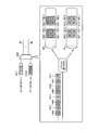
- FIG. 6B is a diagram of an example of each transmission device facing each other.
- Each of transmission apparatus 600A (first transmission apparatus) and transmission apparatus 600B (second transmission apparatus) shown in FIG. 6-2 has the same configuration as transmission apparatus 600 shown in FIG. As shown in FIG. 6B, transmission apparatuses 600A and 600B are connected to face each other.
- the links between the transmission apparatuses 600A and 600B include aggregation links # 1 to #n that are wireless communication sections.
- the transfer devices 631 to 63n are termination devices on the transmission device 600A side of the aggregation links # 1 to #n.
- the transfer devices 641 to 64n are termination devices on the transmission device 600B side of the aggregation links # 1 to #n.
- a data packet from another device 1 connected to the transmission device 600A is input from the link 1, and is transmitted to any of the transfer devices 631 to 63n via the line IF unit 620 and the transfer processing unit 610 of the transmission device 600A. Is output. Transfer devices 631 to 63n transmit the data packets output from transmission device 600A to transfer devices 641 to 64n, respectively.
- the data packet transmitted to the transfer devices 641 to 64n is input to the transmission device 600B.
- the data packet input to the transmission device 600B is output from the link 2 to another device 2 via the transfer processing unit 610 and the line IF unit 620 of the transmission device 600B.
- the flow of the data packet from the other device 1 to the other device 2 has been described, but the flow of the data packet from the other device 2 to the other device 1 is similarly performed by the aggregation links # 1 to #n. Is transmitted.
- FIG. 7A is a diagram of an example 1 of information stored in the storage unit.
- a table 710 shown in FIG. 7-1 is stored in the storage unit 614 (corresponding information storage unit) shown in FIG.
- the identification information, the guaranteed rate [Mbps], and the guaranteed traffic transfer link are associated with each of the data flows 1 and 2.
- the identification information in the table 710 is information for identifying the data flow.
- the input ports 1 and 2 are associated with the data flows 1 and 2, respectively.
- Each of the input ports 1 and 2 is an input port to which a data flow from another device is input in the line IF unit 620.
- the identification unit 611 identifies the data flow based on the input port to which the data flow is input and the table 710.
- the information for identifying the data flow is not limited to the input port, but information such as a source MAC address, a destination MAC address, a VLAN-ID, a source IP address, a destination IP address, or a combination of these information It may be.
- the guaranteed rate in the table 710 is the guaranteed rate set in the data flow.
- the scheduler 615 acquires the guaranteed rates of the data flows 1 and 2 from the table 710.
- the guaranteed traffic transfer link in the table 710 is an aggregation link that distributes the guaranteed traffic of the data flows 1 and 2.
- aggregation links # 1 and # 2 are associated with data flows 1 and 2, respectively.
- the scheduler 615 distributes the guaranteed traffic 102a of the data flow 1 to the aggregation link # 1, and distributes the guaranteed traffic 103a of the data flow 2 to the aggregation link # 2.
- FIG. 7-2 is a diagram of an example 2 of information stored in the storage unit.
- the storage unit 614 illustrated in FIG. 6A may store a table 710 illustrated in FIG. 7B.
- the peak rate [Mbps] is associated with each of the data flows 1 and 2 in addition to the items shown in FIG.
- the peak rate [Mbps] in the table 710 is a peak rate set for the data flow.
- the scheduler 615 acquires peak rates P2 and P3 of the data flows 1 and 2 from the table 710.
- FIG. 7-3 is a diagram of an example 3 of information stored in the storage unit.
- the storage unit 614 may store a table 710 shown in FIG. 7-3.
- the aggregation links # 1 and # 2 are associated with the data flow 1 as guaranteed traffic transfer links, and the distribution links are guaranteed to the aggregation links # 1 and # 2, respectively.
- a rate is associated.
- the scheduler 615 distributes the guaranteed traffic 102a of the data flow 1 to the aggregation links # 1 and # 2 by 50 [Mbps] based on the table 710 shown in FIG.
- FIG. 8 is a flowchart showing packet reception processing by the transmission apparatus. Each time the transmission apparatus 600 receives a packet to be transferred by link aggregation via the line IF unit 620, for example, the transmission apparatus 600 performs the following processing. First, the identification unit 611 identifies the data flow of the received packet (step S801).
- the transmission processing unit 616 assigns a sequence number corresponding to the data flow identified in step S801 to the received packet (step S802), and ends a series of processing. However, if the order is not guaranteed, step S802 need not be executed.
- the packet processed in each step of FIG. 8 is stored in the buffer of the transmission apparatus 600 as a transmission waiting packet for each data flow.
- FIG. 9 is a flowchart showing packet transmission processing by the transmission apparatus.
- the transmission apparatus 600 repeatedly executes, for example, the following steps for each data flow in a state where the transmission waiting packet is stored in the buffer by the steps shown in FIG.
- the scheduler 615 determines whether or not the transmission waiting packet stored in the buffer can be read as a guarantee packet (guaranteed traffic) or an excess packet (excess traffic) (step S901).
- the determination method in step S901 will be described later (see, for example, FIGS. 10 and 11).
- step S901 when the transmission waiting packet cannot be read (step S901: No), the scheduler 615 ends a series of processes. If the transmission waiting packet can be read (step S901: Yes), the scheduler 615 determines whether or not the transmission packet that can be read can be read as a guarantee packet (step S902).
- step S902 when the packet waiting for transmission can be read as a guarantee packet (step S902: Yes), the scheduler 615 acquires a guarantee packet transfer link of the target data flow from the table 710 (step S903). Next, the scheduler 615 transmits a readable packet to the guaranteed packet transfer link acquired in step S903 (step S904), and the series of processing ends.
- step S902 if the transmission waiting packet can be read as an excess packet instead of a guarantee packet (step S902: No), a link to which the excess packet is distributed is determined (step S905).
- the determination method in step S905 will be described later (see, for example, FIGS. 12 to 19).
- the scheduler 615 transmits a transmission waiting packet to the distribution destination link determined in step S905 (step S906), and the series of processing ends.
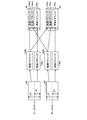
- FIG. 10 is a diagram illustrating an example of a read determination process performed by the transmission apparatus.
- the transmission apparatus 600 manages transmission waiting packets stored in the buffer for each of the data flows 1 to m.
- the monitoring unit 612 includes a token bucket counter 1020 for a guaranteed rate and a token bucket counter 1030 for a peak rate for each of the transmission queues 1011 to 101m of the data flows 1 to m.
- the scheduler 615 uses the guaranteed-rate token bucket counter 1020 and the peak-rate token bucket counter 1030 to determine whether the packet stored in the buffer can be read and whether it is a guaranteed packet or an excess packet. .
- the guaranteed rate token bucket counter 1020 is periodically added with a guaranteed rate token (unit: for example, bit) corresponding to the size of the guaranteed rate.
- the peak rate token bucket counter 1030 is periodically added with a peak rate token (for example, bit) corresponding to the magnitude of the peak rate.
- the token bucket counter 1020 for the guaranteed rate and the token bucket counter 1030 for the peak rate have an upper limit value, and are not added beyond the upper limit value.
- the upper limit values of the token bucket counter 1020 for guaranteed rates and the token bucket counter 1030 for peak rates correspond to the data size that can be read continuously when the transmission queue is accumulated. Note that the peak rate token is set to a larger value than the guaranteed rate token.
- the guaranteed rate of data flow 1 is 50 [Mbps].
- the guaranteed rate token is set to be added to the guaranteed rate token bucket counter 1020 by 50 [kbit].
- the upper limit value of the token bucket counter 1020 for the guaranteed rate is set to 500 [kbit].
- the peak rate of data flow 1 is 100 [Mbps].
- the peak rate token is set to be added to the peak rate token bucket counter 1030 by 100 [kbit].
- the upper limit value of the token bucket counter 1030 for peak rate is set to 1000 [kbit].
- the scheduler 615 reads the packet waiting for transmission as the guaranteed packet.
- the scheduler 615 reads the transmission waiting packet as an excess packet.
- the scheduler 615 distributes and transmits the transmission waiting packet read as the guarantee packet or the excess packet to at least one of the aggregation links # 1 to #n via the switch 1040.
- the transmission waiting packet in the buffer stays until tokens are accumulated in each token bucket counter.
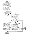
- FIG. 11 is a flowchart illustrating an example of a read determination process performed by the transmission apparatus.
- the transmission apparatus 600 executes each step shown in FIG. 11, for example, to determine whether or not the transmission waiting packet stored in the buffer can be read as a guarantee packet or an excess packet. To do.
- each data flow may be processed one packet at a time in round robin, or the next data flow may be sequentially processed after all the transmission waiting packets of a certain data flow are processed.
- the scheduler 615 obtains the size of a transmission waiting packet that can be read (step S1101). Next, the scheduler 615 acquires the value of the token bucket counter 1020 for the guaranteed rate of the target data flow (step S1102). Next, the scheduler 615 determines whether or not the counter value acquired in step S1102 is greater than or equal to the packet size acquired in step S1101 (step S1103).
- step S1103 when the counter value is equal to or larger than the packet size (step S1103: Yes), the scheduler 615 proceeds to step S1104. That is, the scheduler 615 subtracts tokens for the packet size acquired in step S1101 from the token bucket counters 1020 and 1030 (step S1104). Next, the scheduler 615 determines that the packet waiting for transmission can be read out as a guarantee packet (step S1105), and ends the series of processing.
- step S1103 when the counter value is not equal to or larger than the packet size (step S1103: No), the scheduler 615 acquires the counter value of the token bucket counter 1030 for the peak rate of the target data flow (step S1106). Next, the scheduler 615 determines whether or not the counter value acquired in step S1106 is greater than or equal to the packet size acquired in step S1101 (step S1107).
- step S1107 when the counter value is equal to or larger than the packet size (step S1107: Yes), the scheduler 615 proceeds to step S1108. That is, the scheduler 615 subtracts tokens for the packet size acquired in step S1101 from the token bucket counter 1030 for peak rate (step S1108). Next, the scheduler 615 determines that the transmission waiting packet can be read as an excess packet (step S1109), and ends a series of processing.
- step S1107 when the counter value is not equal to or larger than the packet size (step S1107: No), the scheduler 615 determines that the transmission waiting packet cannot be read (step S1110), and ends the series of processes.
- packets corresponding to the guaranteed rate can be transmitted as guaranteed packets, and packets corresponding to the excess exceeding the guaranteed rate can be transmitted as excess packets with the peak rate as the upper limit.
- FIG. 12 is a flowchart (part 1) illustrating an example 1 of excess packet distribution processing.
- the scheduler 615 determines the WRR pattern (WRR pattern) by executing the following steps when, for example, a change in the transmission rate of each aggregation link, addition or deletion of a data flow, or a change in guaranteed rate occurs. To do.
- the scheduler 615 acquires the transmission rate of each aggregation link from the management unit 613 (step S1201). Next, the scheduler 615 acquires the guaranteed rate and guaranteed traffic transfer link of each data flow from the table 710 (see FIGS. 7-1 to 7-3) stored in the storage unit 614 (step S1202).
- the scheduler 615 calculates the free bandwidth of each aggregation link based on each transmission rate acquired in step S1201 and each guaranteed rate acquired in step S1202 (step S1203).
- the scheduler 615 determines a WRR pattern based on the ratio of the free bandwidth of each aggregation link calculated in step S1203 (step S1204), and ends a series of processing.
- the scheduler 615 has two aggregation links # 1 and # 2, and when the ratio of the free bandwidths of the aggregation links # 1 and # 2 is 1: 1, the aggregation links # 1 and # 2 The order is a WRR pattern. Further, the scheduler 615 uses the WRR pattern in the order of the aggregation links # 1, # 2, # 2, and # 2 when the ratio of the free bandwidth is 1: 3. In addition, the scheduler 615 excludes the aggregation link whose free bandwidth is 0 from the target to which excess packets are distributed.
- FIG. 13 is a flowchart (part 2) illustrating an example 1 of excess packet distribution processing.
- the scheduler 615 executes the following steps. First, the scheduler 615 acquires a WRR pattern determined in step S1204 shown in FIG. 12 and a pointer indicating the position of the current WRR (step S1301).
- the scheduler 615 acquires the aggregation link indicated by the pointer in the WRR pattern acquired in step S1301 (step S1302). For example, when the ratio of the free bandwidth of each aggregation link is 1: 1, the WRR pattern is aggregation links # 1 and # 2, and the pointer indicates the head of the WRR pattern, the aggregation link # 1 is acquired.
- the scheduler 615 increments the WRR pointer for the next reading (step S1303), and ends the series of processing.
- the pointer indicates the head of the WRR pattern
- the reference destination of the pointer incremented in step S1303 is changed to the aggregation link # 2.
- FIG. 14 is a diagram showing a first example of distribution by the determination process shown in FIGS. For example, as a result of each step shown in FIG. 12, it is assumed that the ratio of the free bandwidth of the aggregation links # 1 and # 2 is 1: 1, and the WRR pattern is in the order of the aggregation links # 1 and # 2.
- the guarantee packets 1411 and 1421 indicate the guarantee packets of the data flows 1 and 2, respectively.
- Excess packets 1412 and 1422 indicate the excess packets of the data flows 1 and 2, respectively.
- the guaranteed packets 1411 and 1421 are distributed to the aggregation links # 1 and # 2 associated with the data flows 1 and 2, respectively.
- the first excess packet 1412 in the data flow 1 is distributed to the aggregation link # 1.
- the first excess packet 1422 of the data flow 2 is distributed to the aggregation link # 2.
- the second excess packet 1412 of the data flow 1 is distributed to the aggregation link # 1.
- the second excess packet 1422 of the data flow 2 is distributed to the aggregation link # 2.
- FIG. 15 is a diagram showing a distribution example 2 by the determination process shown in FIGS. 12 and 13.
- the same parts as those shown in FIG. 14 are denoted by the same reference numerals, and description thereof is omitted.
- the ratio of the free bandwidth of the aggregation links # 1, # 2 is 1: 3, and the WRR pattern is in the order of the aggregation links # 1, # 2, # 2, # 2.
- the guaranteed packets 1411 and 1421 are distributed to the aggregation links # 1 and # 2 associated with the data flows 1 and 2, respectively.
- the first excess packet 1412 in the data flow 1 is distributed to the aggregation link # 1.
- the first excess packet 1422 of the data flow 2 is distributed to the aggregation link # 2.
- the second excess packet 1412 of the data flow 1 is distributed to the aggregation link # 2.
- the second excess packet 1422 of the data flow 2 is distributed to the aggregation link # 2.
- excess packets can be distributed according to the size of the free bandwidth of each aggregation link.
- the order of the WRR is not fixed every time, but the start position is shifted for each round. Therefore, in order to manage the start position of the WRR, a pointer for the round start position is also used in addition to the WRR pointer.
- the scheduler 615 determines a WRR pattern by each step shown in FIG.
- FIG. 16 is a flowchart showing an example 2 of excess packet distribution processing.
- the scheduler 615 executes the following steps. First, the scheduler 615 acquires the WRR pattern determined in step S1204 shown in FIG. 12 and a pointer indicating the position of the current WRR (step S1601).
- the scheduler 615 acquires the aggregation link indicated by the pointer in the WRR pattern acquired in step S1601 (step S1602). For example, when the ratio of the free bandwidth of each aggregation link is 1: 1 and the WRR pattern is aggregation links # 1 and # 2, the aggregation link # 1 is acquired when the pointer indicates the head of the WRR pattern. .
- the scheduler 615 determines whether or not the current round is completed (round is 1 round) (step S1603). If the current round has not ended (step S1603: NO), the scheduler 615 increments the WRR pointer for the next reading (step S1604), and ends the series of processes.
- step S1603 when the current round is completed (step S1603: Yes), the scheduler 615 increments the round start position pointer (step S1605). Thereby, the start position of WRR in the next round can be shifted.
- the ratio of the free bandwidth of each aggregation link is 1: 3, and the WRR pattern is the aggregation links # 1, # 2, # 2, and # 2.
- the reading order is aggregation links # 1, # 2, # 2, and # 2.
- the reading order is link aggregation links # 2, # 2, # 2, and # 1.
- the reading order is aggregation links # 2, # 2, # 1, and # 2.
- the reading order is aggregation links # 2, # 1, # 2, and # 2.
- the scheduler 615 sets the WRR pointer for the next round to the position of the round start position pointer incremented in step S1605 (step S1606), and ends the series of processing.
- FIG. 17 is a diagram showing a first example of distribution by the determination process shown in FIG. 17, parts that are the same as the parts shown in FIG. 14 are given the same reference numerals, and descriptions thereof will be omitted.
- the ratio of the free bandwidth of the aggregation links # 1 and # 2 is 1: 1, and the WRR pattern is in the order of the aggregation links # 1 and # 2.
- the guarantee packets 1411 and 1421 are distributed to the aggregation links # 1 and # 2 associated with the data flows 1 and 2, respectively.
- the first excess packet 1412 in the data flow 1 is distributed to the aggregation link # 1.
- the first excess packet 1422 of the data flow 2 is distributed to the aggregation link # 2.
- the second excess packet 1412 of the data flow 1 is distributed to the aggregation link # 2.
- the second excess packet 1422 in the data flow 2 is distributed to the aggregation link # 1.
- FIG. 18 is a diagram showing a distribution example 2 by the determination process shown in FIG. 18, parts that are the same as the parts shown in FIG. 17 are given the same reference numerals, and descriptions thereof will be omitted.
- the ratio of the free bandwidth of the aggregation links # 1, # 2 is 1: 3, and the WRR pattern is in the order of the aggregation links # 1, # 2, # 2, # 2.
- the guarantee packets 1411 and 1421 are distributed to the aggregation links # 1 and # 2 associated with the data flows 1 and 2, respectively.
- the first excess packet 1412 in the data flow 1 is distributed to the aggregation link # 1.
- the first excess packet 1422 of the data flow 2 is distributed to the aggregation link # 2.
- the second excess packet 1412 of the data flow 1 is distributed to the aggregation link # 2.
- the second excess packet 1422 of the data flow 2 is distributed to the aggregation link # 2.
- the third excess packet 1412 of the data flow 1 is distributed to the aggregation link # 2.
- the third excess packet 1422 of the data flow 2 is distributed to the aggregation link # 2.
- the fourth excess packet 1412 in the data flow 1 is distributed to the aggregation link # 2.
- the fourth excess packet 1422 in the data flow 2 is distributed to the aggregation link # 1.
- the fifth to eighth excess packets 1412 and 1422 of the data flows 1 and 2 described below are not shown in FIG.
- the fifth excess packet 1412 of the data flow 1 is distributed to the aggregation link # 2.
- the fifth excess packet 1422 in the data flow 2 is distributed to the aggregation link # 2.
- the sixth excess packet 1412 in the data flow 1 is distributed to the aggregation link # 1.
- the sixth excess packet 1422 in the data flow 2 is distributed to the aggregation link # 2.
- the seventh excess packet 1412 in the data flow 1 is distributed to the aggregation link # 2.
- the seventh excess packet 1422 of the data flow 2 is distributed to the aggregation link # 1.
- the eighth excess packet 1412 of the data flow 1 is distributed to the aggregation link # 2.
- the eighth excess packet 1422 of the data flow 2 is distributed to the aggregation link # 2.
- the sliding WRR it is possible to distribute excess packets according to the size of the free bandwidth of each aggregation link. Further, according to the sliding WRR, the excess packets of each data flow can be distributed more evenly without the excess packets of each data flow being biased to a specific link. For this reason, for example, when the transmission speed of the aggregation link decreases, the influence of delay and discard on each data flow becomes the same, and the fairness between the data flows can be improved.
- FIG. 19 is a flowchart showing an example 3 of excess packet distribution processing.
- the scheduler 615 executes the following steps. First, the scheduler 615 acquires the transmission rate of each aggregation link (step S1901). Next, the scheduler 615 obtains the guaranteed rate and guaranteed traffic transfer link for each data flow from the table 710 (see FIGS. 7-1 to 7-3) stored in the storage unit 614 (step S1902).
- the scheduler 615 acquires the amount of excess traffic of each aggregation link (step S1903). For example, when the scheduler 615 determines to read as an excess packet in step S1109 in FIG. 11, the size of the packet to be read is accumulated and stored as the transmission data amount. Then, the scheduler 615 can acquire the amount of excess traffic by converting the accumulated transmission data amount into the traffic amount per unit time.
- the scheduler 615 calculates the excess traffic usage rate of each aggregation link based on the amount of excess traffic of each aggregation link acquired in step S1903 (step S1904).
- the usage rate of excess traffic is the ratio of excess packet traffic in the free bandwidth.
- the transmission data amount per second is 10 [Mbit]
- the transmission traffic amount is 10 [Mbps].
- the transmission rate is 100 [Mbps]
- the total guaranteed rate of transmission is 50 [Mbps]
- the traffic amount of excess packets is 10 [Mbps].
- the scheduler 615 selects the aggregation link with the minimum excess traffic usage rate calculated in step S1904 as the excess traffic distribution destination link (step S1905), and ends the series of processes.
- the scheduler 615 distributes excess packets according to the size of the free bandwidth of each aggregation link. Note that the method of determining the distribution destination link is not limited to the examples shown in FIGS. 12 to 19, and other methods may be used.
- FIG. 20 is a diagram illustrating a first example of a transmission system to which the transmission apparatus is applied. 20, parts that are the same as the parts shown in FIG. 6-2 are given the same reference numerals, and descriptions thereof will be omitted.
- a radio transmission system 2000 shown in FIG. 20 includes a radio base station 2010, a transmission device 600A, transfer devices 631 to 63n, transfer devices 641 to 64n, a transmission device 600B, and a radio system core network 2020. Yes.
- the transmission apparatus 600A and the transmission apparatus 600B transfer each data flow transmitted and received between the radio base station 2010 and the radio system core network 2020 by link aggregation using the aggregation links # 1 to #n. As described above, the transmission apparatus 600A and the transmission apparatus 600B can be applied to a backhaul line portion between the radio base station 2010 and the radio system core network 2020 of the radio transmission system 2000.
- FIG. 21 is a diagram illustrating a second example of the transmission system to which the transmission device is applied.
- a transmission system 2100 shown in FIG. 21 includes a user base LAN 2110, a transmission device 600A, transfer devices 631 to 63n, transfer devices 641 to 64n, a transmission device 600B, and a wide area backbone 2120.
- the transmission device 600A and the transmission device 600B transfer each data flow transmitted and received between the user base LAN 2110 and the wide area backbone 2120 by link aggregation using the aggregation links # 1 to #n.
- the transmission device 600A and the transmission device 600B can be applied to the VPN connection link portion between the user base LAN 2110 and the wide area backbone 2120 of the transmission system 2100.
- traffic for the guaranteed rate out of the traffic is preferentially distributed to the radio links, and traffic exceeding the guaranteed rate is free in each radio link. Can be distributed to bands. Thereby, the throughput can be improved while guaranteeing the bandwidth.
- A1 to A3 Guaranteed rate P2 P3 Peak rate 101 to 103 Traffic 101a, 102a, 103a Guaranteed traffic 101b, 102b, 103b Excess traffic 631 to 63n Transfer device 641 to 64n Transfer device 1011 to 101m Transmission queue 1020, 1030 Token bucket counter 1040 Switch 1411, 1421 Guaranteed packet 1412, 1422 Excess packet 2000 Wireless transmission system 2010 Wireless base station 2020 Wireless system core network 2100 Transmission system 2110 User base LAN 2120 Wide-area backbone
Landscapes
- Engineering & Computer Science (AREA)
- Computer Networks & Wireless Communication (AREA)
- Signal Processing (AREA)
- Mobile Radio Communication Systems (AREA)
- Data Exchanges In Wide-Area Networks (AREA)
Abstract
伝送装置(100)は、アグリゲーションリンク(#1,#2)を用いてデータフローを伝送する。伝送装置(100)は、記憶部(110)と、分割部(120)と、振分部(130)と、を備えている。記憶部(110)は、データフローにおいて保証すべき保証レート(A1)を取得する。分割部(120)は、データフローのトラフィック(101)を、記憶部(110)によって取得された保証レート(A1)の分の保証トラフィック(101a)と、保証レート(A1)を超える分の超過トラフィック(101b)と、に分割する。振分部(130)は、分割部(120)によって分割された保証トラフィック(101a)を超過トラフィック(101b)より優先的にアグリゲーションリンク(#1,#2)の少なくともいずれかに振り分ける。また、振分部(130)は超過トラフィック(101b)をアグリゲーションリンク(#1,#2)の空き帯域に振り分ける。
Description
本発明は、伝送装置、伝送方法および伝送システムに関する。
伝送システムにおいて、通信事業者がユーザに対して提供するネットワーク接続サービスの一つに、通信事業者のネットワークを複数のユーザで共用しつつ、各ユーザの契約に基づいて一定の通信帯域を常に確保する帯域保証サービスがある。帯域保証サービスは、たとえば、重要度が高く、高い可用性が要求される通信を行う場合に用いられる。たとえば、帯域保証サービスは、企業ユーザのVPN(Virtual Private Network:仮想プライベートネットワーク)接続や、モバイル通信事業者における無線基地局とコアネットワークの間のバックホール接続などに用いられる。
このような帯域保証サービスは、一例として、広域イーサネット(登録商標)サービスの提供や技術仕様の策定など、MAN(Metropolitan Area Network)でのイーサネット技術の利用を推進するメトロイーサネットフォーラム(Metro Ethernet Forum)においても開示されている(たとえば、下記非特許文献1,2参照。)。
たとえば、メトロイーサネットフォーラムが策定した技術仕様においては、広域イーサネット網におけるイーサネット仮想コネクション(Ethernet Virtual Connection)サービスを提供する際の帯域パラメータとして、保証帯域を意味するCIR(Committed Information Rate)や、保証はされないが帯域に空きが有る場合に送信可能な上限の帯域を意味するEIR(Excess Information Rate)などのパラメータが規定されている。なお、「Ethernet」は登録商標である。
帯域保証サービスを提供する通信事業者のネットワークの接続リンクには、メタルケーブルや光ファイバケーブルなどの有線リンクだけでなく、マイクロ波を用いる無線リンクも使用される。また、無線リンクの場合には、無線チャネルの品質に応じて、品質がよい場合には高速な変調方式(たとえば64QAM、128QAM、256QAMなど)を用い、品質が悪い場合には低速だがエラー耐性の高い変調方式(たとえばBPSKやQPSKなど)を用いるなどの制御が行われることもある。このような制御は、たとえば適応変調と呼ばれる。適応変調により、無線リンクの場合には伝送速度も変化する。
帯域保証サービスにおいては、保証レートは満足すべきSLA(Service Level Agreement)の項目としてユーザに対して契約を結ぶことが考えられる。一方で、ピークレートはSLAの対象外であるため、保証レート分のトラフィックさえ転送できていれば、ピークレートまでのトラフィックが転送されなくても、サービス契約違反とはならない。一方、ユーザにとってはより高いスループットで通信を行える方が快適であるため、なるべくピークレートまでのトラフィックが転送できることが望ましい。
また、より高速なデータ転送を実現するために、複数の通信リンクを束ねて大容量のリンクとして使用するリンクアグリゲーションが知られている(たとえば、下記特許文献1~3および下記非特許文献3~5参照。)。リンクアグリゲーションの例としては、有線のイーサネットリンクについてリンクアグリゲーションを行う場合の技術規格としてIEEE802.3adがある。
IEEE802.3adにおいては、全てのイーサネットリンクの伝送速度は同じ前提となっており、データパケットにシーケンス番号を付与せず、データフロー(Conversation)においてパケットの順序保証を実現する。このため、複数のイーサネットリンクを束ねているにも関わらず、データフローごとにいずれか1つのイーサネットリンクを使ってデータパケットを転送することになる。
Metro Ethernet Forum、"Introducing the Specifications of the MEF An Overview of MEF 6.1 and MEF 10.1"、Page35,36、[online]、[平成22年12月24日検索]、インターネット<URL:http://metroethernetforum.org/PPT_Documents/MEF6-1_and_%20MEF10-1_Overview.ppt>
Metro Ethernet Forum、"MEF Technical Specification MEF10.2 Ethernet Services Attributes Phase2"、Page37、"7.11.1 Standard Bandwidth Profile Parameters and Algorithm"、[online]、[平成22年12月24日検索]、インターネット<URL:http://metroethernetforum.org/PDF_Documents/technical-specifications/MEF10.2.pdf>
IEEE Std 802.3ad-2000,2000/03/30、"Amendment to Carrier Sense Multiple Access with Collision Detection(CSMA/CD) Access Method and Physical Layer Specifications"、[online]、[平成22年12月24日検索]、インターネット<URL:http://voiplab.niu.edu.tw/IEEE/obsolete/802.3/802.3ad-2000.pdf>
石津,村上,原田、「コグニティブ無線ネットワークにおいて柔軟なトラフィック制御を可能とするリンクアグリゲーションプラットフォーム」、IEICE RCS研究会、2010年8月27日
橋口等、「異種無線リンクアグリゲーション方式における最適トラフィック分配制御の解析」、信学技報、vol.109,no.383,SR2009-74,pp.1-8、2010年1月
しかしながら、上述した従来技術では、トラフィックのスループットを向上させることができないという問題がある。具体的には、アグリゲーションを行うそれぞれの各無線リンクは、たとえば周波数選択性フェージングや適応変調などによって伝送速度が変動する。そして、データフローを振り分けた無線リンクの伝送速度がデータフローのトラフィック量よりも低下すると、他の無線リンクに空き帯域があっても、データフローの一部に廃棄や遅延が発生し、スループットが低下する。
開示の伝送装置、伝送方法および伝送システムは、上述した問題点を解消するものであり、帯域を保証しつつスループットを向上させることを目的とする。
上述した課題を解決し、目的を達成するため、開示技術においては、複数の無線リンクを用いてデータフローを伝送する伝送装置が、前記データフローにおいて保証すべき保証レートを取得し、前記データフローのトラフィックを、取得した前記保証レートの分の第一トラフィックと、前記保証レートを超える分の第二トラフィックと、に分割し、分割した前記第一トラフィックを前記第二トラフィックより優先的に前記複数の無線リンクの少なくともいずれかに振り分け、前記第二トラフィックを前記複数の無線リンクの空き帯域に振り分ける。
開示の伝送装置、伝送方法および伝送システムによれば、帯域を保証しつつスループットを向上させることができるという効果を奏する。
以下に添付図面を参照して、開示技術の好適な実施の形態を詳細に説明する。
(実施の形態)
図1-1は、実施の形態にかかる伝送装置の構成例1を示す図である。図1-1に示すように、実施の形態にかかる伝送装置100は、記憶部110と、分割部120と、振分部130と、を備えている。伝送装置100は、複数の無線リンクを用いたリンクアグリゲーションにより対向装置へデータフローを伝送する。ここでは、伝送装置100は、アグリゲーションリンク#1,#2を用いたリンクアグリゲーションによりデータフローを伝送する。アグリゲーションリンク#1,#2のそれぞれは無線リンクである。
図1-1は、実施の形態にかかる伝送装置の構成例1を示す図である。図1-1に示すように、実施の形態にかかる伝送装置100は、記憶部110と、分割部120と、振分部130と、を備えている。伝送装置100は、複数の無線リンクを用いたリンクアグリゲーションにより対向装置へデータフローを伝送する。ここでは、伝送装置100は、アグリゲーションリンク#1,#2を用いたリンクアグリゲーションによりデータフローを伝送する。アグリゲーションリンク#1,#2のそれぞれは無線リンクである。
データフローは、たとえば、入力リンク(入力ポート)、宛先または送信元のMACアドレス、宛先または送信元のIPアドレス、宛先または送信元のポート番号、上位レイヤの種別などによって識別されるパケットのグループである。
転送装置141,142は、伝送装置100から振り分けられたトラフィックをそれぞれアグリゲーションリンク#1,#2によって転送する転送装置である。転送装置141,142は、それぞれアグリゲーションリンク#1,#2の状態を取得して管理する。アグリゲーションリンク#1,#2の状態は、たとえばアグリゲーションリンク#1,#2の無線状態などによって変動する伝送速度である。
また、転送装置141,142は、各データフローの保証レートおよびピークレートなどのパラメータを取得する。そして、転送装置141,142は、伝送装置100からの入力パケットについて、データフロー1,2のいずれのデータパケットであるかを識別するとともに、データパケットのサイズや前回送信からの経過時間から転送トラフィック量の監視を行う。また、転送装置141,142は、入力されたデータフロー1,2のトラフィックがピークレートを超えている場合は、トラフィックシェーピングを行いながら各トラフィックの伝送を行う。
ここでは、伝送装置100が1つのデータフローをリンクアグリゲーションにより伝送する場合について説明する。トラフィック101は、伝送装置100が伝送するデータフローのトラフィックである。トラフィック101において、横方向は時間を示し、縦方向はトラフィック量(レート)を示している。保証レートA1は、伝送装置100が伝送するデータフローにおいて保証すべき保証レートを示している。ここでは、トラフィック101は、保証レートA1を超えるトラフィック量を有している。
記憶部110は、伝送装置100が伝送するデータフローの保証レートA1を記憶している。分割部120および振分部130は、伝送装置100が伝送するデータフローのトラフィック量およびアグリゲーションリンク#1,#2の各伝送速度に基づいて、データフローのトラフィックの出力スケジューリングを行う。ここで、アグリゲーションリンク#1,#2の各伝送速度の情報は、転送装置141,142からの通知または伝送装置100から転送装置141,142への問い合わせによって取得することができる。
分割部120は、記憶部110に記憶された保証レートA1を取得する。そして、分割部120は、トラフィック101を、保証レートA1の分の保証トラフィック101a(第一トラフィック)と、保証レートA1を超える分の超過トラフィック101b(第二トラフィック)と、に分割する。分割部120は、分割した保証トラフィック101aおよび超過トラフィック101bを振分部130へ出力する。
振分部130は、分割部120から出力された保証トラフィック101aを、アグリゲーションリンク#1,#2の少なくともいずれかに振り分ける。また、振分部130は、保証トラフィック101aを、超過トラフィック101bより優先的に振り分ける。
また、振分部130は、分割部120から出力された超過トラフィック101bをアグリゲーションリンク#1,#2の空き帯域に振り分ける。このように、振分部130は、超過トラフィック101bを保証トラフィック101aと分けてアグリゲーションリンク#1,#2の空き帯域に振り分ける。これにより、アグリゲーションリンク#1,#2の空き帯域を活用して超過トラフィック101bを伝送し、スループットを向上させることができる。
たとえば、振分部130は、保証トラフィック101aをアグリゲーションリンク#1に振り分けたとする。このとき、アグリゲーションリンク#1に超過トラフィック101bを振り分ける帯域がない場合は、振分部130は、超過トラフィック101bをアグリゲーションリンク#2に振り分ける。これにより、超過トラフィック101bの遅延や廃棄を回避し、スループットを向上させることができる。
振分部130は、アグリゲーションリンク#1に振り分けたトラフィックを転送装置141へ出力し、アグリゲーションリンク#2に振り分けたトラフィックを転送装置142へ出力する。これにより、データフローのうちのアグリゲーションリンク#1に振り分けられたトラフィックがアグリゲーションリンク#1によって伝送される。また、データフローのうちのアグリゲーションリンク#2に振り分けられたトラフィックがアグリゲーションリンク#2によって伝送される。
図1-2は、実施の形態にかかる伝送装置の構成例2を示す図である。図1-2において、図1-1に示した部分と同様の部分については同一の符号を付して説明を省略する。伝送装置100は、アグリゲーションリンク#1,#2を用いて複数のデータフローを伝送してもよい。この場合は、図1-2に示すように、伝送装置100は、図1-1に示した構成に加えて識別部160を備えていてもよい。ここでは、伝送装置100は、データフロー1,2を伝送するとする。
識別部160には、伝送装置100が伝送する各データフローが入力される。識別部160は、入力されたデータフローがデータフロー1,2のいずれであるかを識別する。ここで、データフロー1,2のトラフィックをそれぞれトラフィック102,103とする。保証レートA2,A3は、それぞれデータフロー1,2の保証レートである。
分割部120および振分部130は、識別部160によって識別されたデータフロー1,2のそれぞれについて、トラフィック量を監視しながら、トラフィックの出力スケジューリングを行う。
分割部120は、識別部160から出力されたデータフロー1,2のそれぞれのトラフィックを、保証トラフィックおよび超過トラフィックに分割する。具体的には、分割部120は、トラフィック102を、保証レートA2の分の保証トラフィック102aと、保証レートA2を超過する分の超過トラフィック102bと、に分割する。また、分割部120は、トラフィック103を、保証レートA3の分の保証トラフィック103aと、保証レートA3を超過する分の超過トラフィック103bと、に分割する。
振分部130は、分割部120によって分割された保証トラフィック102a,103aを、アグリゲーションリンク#1,#2の少なくともいずれかに振り分ける。また、振分部130は、保証トラフィック102a,103aを、超過トラフィック102b,103bよりも優先的に振り分ける。ここでは、振分部130は、保証トラフィック102aをアグリゲーションリンク#1に振り分け、保証トラフィック103aをアグリゲーションリンク#2に振り分けている。また、振分部130は、アグリゲーションリンク#2の空き帯域に、超過トラフィック102b,103bを振り分けている。図1-2においては、保証トラフィック103aおよび超過トラフィック103bに対して累積させたトラフィック量として超過トラフィック102bを図示している。
ここで、アグリゲーションリンク#1の伝送速度が50[Mbps]、アグリゲーションリンク#2の伝送速度が200[Mbps]である場合について説明する。振分部130は、データフロー1に対応付けられたアグリゲーションリンク#1に保証トラフィック102aを振り分ける。また、振分部130は、データフロー2に対応付けられたアグリゲーションリンク#2に保証トラフィック103aを振り分ける。
つぎに、振分部130は、アグリゲーションリンク#1の空き帯域を、アグリゲーションリンク#1の伝送速度50[Mbps]から、アグリゲーションリンク#1に振り分けた保証トラフィック102aのレート50[Mbps]を減算することにより算出する。ここでは、アグリゲーションリンク#1の空き帯域は0[Mbps]となる。
また、振分部130は、アグリゲーションリンク#2の空き帯域を、アグリゲーションリンク#2の伝送速度200[Mbps]から、アグリゲーションリンク#2に振り分けた保証トラフィック103aのレート50[Mbps]を減算することにより算出する。ここでは、アグリゲーションリンク#2の空き帯域は150[Mbps]となる。
したがって、アグリゲーションリンク#1はデータフロー1の保証トラフィック102aのみで帯域を使い切る状態となる。このため、振分部130は、データフロー1の超過トラフィック102bおよびデータフロー2の超過トラフィック103bをともにアグリゲーションリンク#2に振り分ける。
ここで、データフロー1,2の保証レートA2,A3は、それぞれアグリゲーションリンク#1,#2の最低の伝送速度以下の範囲で設定されている。たとえば、アグリゲーションリンク#1,#2の最低の伝送速度はそれぞれ50[Mbps]とする。アグリゲーションリンク#1へ振り分けられた50[Mbps]のデータフロー1の保証トラフィック101aは、アグリゲーションリンク#1の伝送速度が50[Mbps]以下になることはないため、全てアグリゲーションリンク#1によって伝送される。
また、アグリゲーションリンク#2へ振り分けられた保証トラフィック103aおよび超過トラフィック102b,103bは、超過トラフィック102b,103bの合計が150[Mbps]以下の場合は全てアグリゲーションリンク#2によって伝送される。
また、アグリゲーションリンク#2の伝送速度が低下して50[Mbps]になった場合は、転送装置142はアグリゲーションリンク#2の帯域を全てデータフロー2の各トラフィックに使用してデータフロー2について帯域保証を行う。この時、データフロー1の全てのトラフィック(超過トラフィック102b)およびデータフロー2の超過トラフィック103bは、転送装置142のバッファに滞留され、またはバッファに空きが無い場合には廃棄される。
なお、データパケットの順序保証を行う場合には、伝送装置100は、たとえば入力パケットに対し、データフローごとのシーケンス番号を付与してもよい。この場合は、リンクアグリゲーションを介した受信側の伝送装置(不図示)では、データフローごとにシーケンス番号に基づいてデータパケットの順序整列を行ってからデータパケットの宛先となる他の装置へ向けて出力を行う。
図1-3は、実施の形態にかかる伝送装置の構成例3を示す図である。図1-3において、図1-2に示した部分と同様の部分については同一の符号を付して説明を省略する。図1-3に示すように、伝送装置100は、図1-2に示した構成に加えて整形部170を備えていてもよい。ピークレートP2,P3は、それぞれデータフロー1,2に設定されたピークレートを示している。
記憶部110(第二記憶部)は、データフロー1,2のピークレートP2,P3を記憶している。整形部170は、記憶部110に記憶されたピークレートP2,P3を取得する。そして、整形部170は、識別部160によって識別されたデータフロー1,2について、伝送レートがそれぞれピークレートP2,P3を超えないように整形するトラフィックシェーピングを行う。整形部170は、たとえばデータパケットの出力間隔を調整することによってトラフィックシェーピングを行う。
分割部120は、整形部170によってトラフィックシェーピングが行われたデータフロー1,2の各トラフィックをそれぞれ保証トラフィック102a,103aおよび超過トラフィック102b,103bに分割する。
ここで、ピークレートP2,P3はそれぞれ100[Mbps]であるとする。そして、伝送装置100へ入力されたデータフロー1,2のトラフィック102,103にはそれぞれピークレートP2,P3を超えるバーストが含まれているとする。
分割部120および振分部130は、整形部170においてピークレートP2,P3でのトラフィックシェーピングを行ってから各トラフィックをアグリゲーションリンク#1,#2へ振り分ける。これにより、超過トラフィック102b,103bがどのような割合でアグリゲーションリンク#1,#2に振り分けられたとしても、受信側の伝送装置から出力される各データフローのトラフィックは、各ピークレート以下の範囲となる。
転送装置141は、アグリゲーションリンク#1に対応付けられたデータフロー1については、保証レートA2による帯域保証およびピークレートP2の制御を行う。また、転送装置141は、アグリゲーションリンク#1に対応付けられていないデータフロー2については、ピークレートP3から保証レートA3を減じたレート、すなわち超過トラフィック103bを全て振り分けた場合のレートをピークレートとして制御する。
転送装置142は、アグリゲーションリンク#2に対応付けられたデータフロー2については、保証レートA3による帯域保証およびピークレートP3の制御を行う。また、転送装置142は、アグリゲーションリンク#2に対応付けられていないデータフロー1については、ピークレートP2から保証レートA2を減じたレート、すなわち超過トラフィック102bを全て振り分けた場合のレートをピークレートとして制御する。これにより、各データフローの帯域を保証するとともにトラフィック量をピークレート以下に抑えることができる。
(各トラフィックの振り分け例)
図2は、各トラフィックの振り分け例1を示す図である。図2においては、アグリゲーションリンク#1,#2の伝送速度はいずれも100[Mbps]であるとする。また、データフロー1,2の保証レートA2,A3はいずれも50[Mbps]であるとする。また、データフロー1,2のピークレートP2,P3はいずれも100[Mbps]であるとする。また、データフロー1,2のトラフィック102,103はいずれも100[Mbps]であるとする。
図2は、各トラフィックの振り分け例1を示す図である。図2においては、アグリゲーションリンク#1,#2の伝送速度はいずれも100[Mbps]であるとする。また、データフロー1,2の保証レートA2,A3はいずれも50[Mbps]であるとする。また、データフロー1,2のピークレートP2,P3はいずれも100[Mbps]であるとする。また、データフロー1,2のトラフィック102,103はいずれも100[Mbps]であるとする。
この場合は、保証トラフィック102a,103aをそれぞれアグリゲーションリンク#1,#2に振り分けると、アグリゲーションリンク#1,#2の空き帯域はそれぞれ50[Mbps]となる。そして、データフロー1,2の超過トラフィック102b,103bをそれぞれアグリゲーションリンク#1,#2へ1:1の割合で振り分けるとする。
具体的には、振分部130は、超過トラフィック102bの50[Mbps]のうちの半分の25[Mbps]を超過トラフィック102b1としてアグリゲーションリンク#1へ振り分ける。また、振分部130は、残り半分の25[Mbps]を超過トラフィック102b2としてアグリゲーションリンク#2へ振り分ける。
また、振分部130は、超過トラフィック103bの50[Mbps]のうちの半分の25[Mbps]を超過トラフィック103b1としてアグリゲーションリンク#1へ振り分ける。また、振分部130は、残り半分の25[Mbps]を超過トラフィック103b2としてアグリゲーションリンク#2へ振り分ける。
図3は、各トラフィックの振り分け例2を示す図である。図3は、図2において、アグリゲーションリンク#1,#2の伝送速度がそれぞれ100[Mbps]および200[Mbps]である場合のトラフィックの振り分けの例を示している。この場合は、保証トラフィック102a,103aをそれぞれアグリゲーションリンク#1,#2に振り分けると、アグリゲーションリンク#1,#2の空き帯域はそれぞれ50[Mbps],150[Mbps]となる。そして、データフロー1,2の超過トラフィック102b,103bをそれぞれアグリゲーションリンク#1,#2へ1:3の割合で振り分けるとする。
具体的には、振分部130は、超過トラフィック102bの50[Mbps]のうちの1/4の12.5[Mbps]を超過トラフィック102b1としてアグリゲーションリンク#1へ振り分ける。また、振分部130は、残り3/4の37.5[Mbps]を超過トラフィック102b2としてアグリゲーションリンク#2へ振り分ける。
また、振分部130は、超過トラフィック103bの50[Mbps]のうちの1/4の12.5[Mbps]を超過トラフィック103b1としてアグリゲーションリンク#1へ振り分ける。また、振分部130は、残り3/4の37.5[Mbps]を超過トラフィック103b2としてアグリゲーションリンク#2へ振り分ける。
図4は、各トラフィックの振り分け例3を示す図である。図4は、図2において、データフロー1の保証レートA2がアグリゲーションリンク#1の最低の伝送レートより大きい場合を示している。アグリゲーションリンク#1,#2の伝送速度は、それぞれ50[Mbps],200[Mbps]であるとする。また簡単のため、入力トラフィックはデータフロー1のみであるとする。また、保証レートA2およびピークレートP2はそれぞれ100[Mbps]および200[Mbps]であるとする。
また、アグリゲーションリンク#1,#2の最低の伝送速度はいずれも50[Mbps]であるとする。したがって、アグリゲーションリンク#1が最低の伝送速度に低下した状態となっている。図4のようにデータフロー1の保証レートA2がアグリゲーションリンク#1の最低の伝送レートより大きい場合には、データフロー1の保証トラフィック102aをアグリゲーションリンク#1,#2に分配して帯域保証を行う。
具体的には、振分部130は、100[Mbps]の保証トラフィック102aを、アグリゲーションリンク#1,#2に対して、それぞれ保証トラフィック102a1,102a2として50[Mbps]ずつに分配して振り分ける。
また、振分部130は、超過トラフィック102bについては、図2の場合と同様にアグリゲーションリンク#1,#2の空き帯域に応じて振り分ける。具体的には、振分部130は、アグリゲーションリンク#1の空き帯域が0[Mbps]であるため、100[Mbps]の超過トラフィック102bはアグリゲーションリンク#2へ振り分ける。
また、転送装置141,142に設定する保証レートは、たとえば、それぞれの分配保証レートである50[Mbps]とする。また、転送装置141,142に設定するピークレートは、たとえば、分配保証レートと全ての超過トラフィックが振り分けられた場合のレートである150[Mbps]とする。
なお、データフロー1の保証レートA2が80[Mbps]である場合には、保証トラフィック102a1,102a2をそれぞれ40[Mbps]としてもよいし、それぞれ50[Mbps]と30[Mbps]としてもよい。また、データフロー1の保証レートA2が150[Mbps]である場合には、たとえば、転送装置を追加してアグリゲーションリンクを3つとし、保証トラフィック102aを3つのアグリゲーションリンクにそれぞれ50[Mbps]ずつに振り分けてもよい。
図5は、各トラフィックの振り分け例4を示す図である。図5は、図4の状態において、アグリゲーションリンク#1,#2の伝送速度がそれぞれ100[Mbps],200[Mbps]である場合のトラフィックの振り分けの例を示している。この場合は、アグリゲーションリンク#1,#2の空き帯域は、それぞれ50[Mbps],150[Mbps]となる。
振分部130は、たとえば、保証トラフィック102aについては、図4の場合と同様に保証トラフィック102a1,102a2としてそれぞれアグリゲーションリンク#1,#2に振り分ける。また、振分部130は、データフロー1の超過トラフィック102bについては、アグリゲーションリンク#1,#2へ1:3の割合で振り分ける。具体的には、振分部130は、データフロー1の100[Mbps]の超過トラフィック102bのうち1/4の25[Mbps]を超過トラフィック102b1としてアグリゲーションリンク#1へ振り分ける。また、振分部130は、残り3/4の75[Mbps]を超過トラフィック102b2アグリゲーションリンク#2へ振り分ける。
(伝送装置の具体例)
図6-1は、伝送装置の具体例を示す図である。図6-1に示す伝送装置600は、図1-1~図1-3に示した伝送装置100の具体例である。図6-1に示すように、伝送装置600は、転送処理部610と、回線IF部620と、を備えている。回線IF部620は、伝送装置600に接続された各リンクを収容する通信インターフェースである。
図6-1は、伝送装置の具体例を示す図である。図6-1に示す伝送装置600は、図1-1~図1-3に示した伝送装置100の具体例である。図6-1に示すように、伝送装置600は、転送処理部610と、回線IF部620と、を備えている。回線IF部620は、伝送装置600に接続された各リンクを収容する通信インターフェースである。
伝送装置600は、回線IF部620を介して、1つ以上のリンクにより、無線基地局やサーバなどの他の装置と接続される。また、伝送装置600は、回線IF部620を介して、n個(n≧2)のアグリゲーションリンク#1~#nにより、対向側の伝送装置と接続される。ここでは、1つの回線IF部620によって各リンクを収容する構成とするが、複数の回線IF部によって各リンクを収容する構成としてもよい。
転送処理部610は、たとえばDSP(Digital Signal Processor)やFPGA(Field Programmable Gate Array)などの演算回路によって実現することができる。転送処理部610は、識別部611と、監視部612と、管理部613と、記憶部614と、スケジューラ615と、送信処理部616と、受信処理部617と、を備えている。
図1-2,図1-3に示した識別部160は、たとえば識別部611によって実現することができる。識別部611は、他の装置からリンクおよび回線IF部620を介して受信したパケットについて、データフローの識別を行う。データフローの識別は、たとえば、入力リンク(入力ポート)、宛先または送信元のMACアドレス、宛先または送信元のIPアドレス、宛先または送信元のポート番号、上位レイヤの種別、その他のデータ種別を表す識別子などに基づいて行うことができる。
図1-1~図1-3に示した分割部120および振分部130は、たとえば監視部612、管理部613およびスケジューラ615によって実現することができる。監視部612は、識別部611によって識別されたデータフローごとに、パケットのサイズおよび送信時刻に基づき、転送されるトラフィック量を監視する。トラフィック量は、たとえば単位時間当たりのデータ量である。たとえば、監視部612は、転送されるトラフィックのバッファに格納されたデータの量を取得することでトラフィック量を監視する。
管理部613(速度取得部)は、アグリゲーションリンク#1~#nの伝送速度を取得する。ここで、アグリゲーションリンク#1~#nの伝送速度は、たとえば、アグリゲーションリンク#1~#nに含まれる無線通信区間の伝送速度である。無線通信区間の伝送速度は、たとえば、無線通信区間の電波状態の変動や、変調方式の切替などによって変化する。管理部613は、アグリゲーションリンク#1~#nに含まれる無線通信区間を終端する各転送装置からアグリゲーションリンク#1~#nの伝送速度を取得する。
図1-1~図1-3に示した記憶部110は、たとえば記憶部614によって実現することができる。記憶部614は、データフローについての保証レート、ピークレートなどのパラメータ、保証レート分のトラフィックの振り分け先となる所定のアグリゲーションリンクの情報などを記憶する(たとえば図7-1~図7-3参照)。
スケジューラ615は、監視部612によって監視される各データフローのトラフィック量と、管理部613によって管理される各アグリゲーションリンクの伝送速度に基づいて、各アグリゲーションリンクへのデータパケット(トラフィック)の振り分けを行う。
送信処理部616は、データパケットの順序保証のために、伝送装置600から送信するデータパケットへのシーケンス番号の付与を行う。なお、順序保証を行わず、シーケンス番号が不要な場合には、送信処理部616を省いた構成としてもよい。受信処理部617は、伝送装置600が受信したデータパケットに付与されたシーケンス番号に基づいてデータパケットの順序整列処理を行う。なお、順序保証を行わず、順序整列処理が不要な場合には、受信処理部617を省いた構成としてもよい。
図6-2は、互いに対向する各伝送装置の一例を示す図である。図6-2に示す伝送装置600A(第一伝送装置)および伝送装置600B(第二伝送装置)のそれぞれは、図6-1に示した伝送装置600と同様の構成である。図6-2に示すように、伝送装置600A,600Bを互いに対向させて接続する。
伝送装置600A,600Bとの間のリンクには無線通信区間であるアグリゲーションリンク#1~#nが含まれる。転送装置631~63nはアグリゲーションリンク#1~#nの伝送装置600Aの側の終端装置である。転送装置641~64nはアグリゲーションリンク#1~#nの伝送装置600Bの側の終端装置である。
たとえば、伝送装置600Aに接続される他の装置1からのデータパケットは、リンク1から入力され、伝送装置600Aの回線IF部620および転送処理部610を介して転送装置631~63nのいずれかへ出力される。転送装置631~63nは、伝送装置600Aから出力されたデータパケットをそれぞれ転送装置641~64nへ伝送する。
転送装置641~64nへ伝送されたデータパケットは、伝送装置600Bへ入力される。伝送装置600Bへ入力されたデータパケットは、伝送装置600Bの転送処理部610および回線IF部620を介して、リンク2から他の装置2へ出力される。ここでは他の装置1から他の装置2へのデータパケットの流れについて説明したが、他の装置2から他の装置1へのデータパケットの流れについても同様に、アグリゲーションリンク#1~#nによって伝送される。
(記憶部に記憶される情報の例)
図7-1は、記憶部に記憶される情報の例1を示す図である。図6-1に示した記憶部614(対応情報記憶部)には、たとえば図7-1に示すテーブル710が記憶される。テーブル710においては、データフロー1,2のそれぞれに対して、識別情報と、保証レート[Mbps]と、保証トラフィック転送用リンクと、が対応付けられている。
図7-1は、記憶部に記憶される情報の例1を示す図である。図6-1に示した記憶部614(対応情報記憶部)には、たとえば図7-1に示すテーブル710が記憶される。テーブル710においては、データフロー1,2のそれぞれに対して、識別情報と、保証レート[Mbps]と、保証トラフィック転送用リンクと、が対応付けられている。
テーブル710の識別情報は、データフローを識別するための情報である。ここでは、データフロー1,2に対してそれぞれ入力ポート1,2が対応付けられている。入力ポート1,2のそれぞれは、回線IF部620において他の装置からのデータフローが入力される入力ポートである。識別部611は、データフローが入力された入力ポートとテーブル710とに基づいてデータフローを識別する。なお、データフローを識別するための情報は、入力ポートに限らず、送信元MACアドレス、宛先MACアドレス、VLAN-ID、送信元IPアドレス、宛先IPアドレスなどの情報や、これらの情報の組み合わせなどであってもよい。
テーブル710の保証レートは、データフローに設定された保証レートである。スケジューラ615は、データフロー1,2の保証レートをテーブル710から取得する。テーブル710の保証トラフィック転送用リンクは、データフロー1,2の各保証トラフィックを振り分けるアグリゲーションリンクである。ここでは、データフロー1,2にはそれぞれアグリゲーションリンク#1,#2が対応付けられている。スケジューラ615は、テーブル710に基づいて、データフロー1の保証トラフィック102aをアグリゲーションリンク#1に振り分け、データフロー2の保証トラフィック103aをアグリゲーションリンク#2に振り分ける。
図7-2は、記憶部に記憶される情報の例2を示す図である。伝送装置600がトラフィックシェーピング(たとえば図1-3参照)を行う場合は、図6-1に示した記憶部614には、図7-2に示すテーブル710が記憶されていてもよい。図7-2に示すテーブル710においては、データフロー1,2のそれぞれに対して、図7-1に示した各項目に加えてピークレート[Mbps]が対応付けられている。テーブル710のピークレート[Mbps]は、データフローに設定されたピークレートである。スケジューラ615は、データフロー1,2のピークレートP2,P3をテーブル710から取得する。
図7-3は、記憶部に記憶される情報の例3を示す図である。一つのデータフローの保証トラフィックを複数のアグリゲーションリンクに分配して振り分ける場合(たとえば図4,図5参照)は、記憶部614には、図7-3に示すテーブル710が記憶されていてもよい。図7-3に示すテーブル710においては、データフロー1に対して、保証トラフィック転送用リンクとしてアグリゲーションリンク#1,#2が対応付けられており、アグリゲーションリンク#1,#2のそれぞれに分配保証レートが対応付けられている。
スケジューラ615は、図7-3に示すテーブル710に基づいて、データフロー1の保証トラフィック102aをアグリゲーションリンク#1,#2に50[Mbps]ずつ分配して振り分ける。
(伝送装置の処理)
図8は、伝送装置によるパケットの受信処理を示すフローチャートである。伝送装置600は、リンクアグリゲーションによって転送すべきパケットを回線IF部620を介して受信するごとに、たとえば、以下の処理を行う。まず、識別部611が、受信されたパケットのデータフローを識別する(ステップS801)。
図8は、伝送装置によるパケットの受信処理を示すフローチャートである。伝送装置600は、リンクアグリゲーションによって転送すべきパケットを回線IF部620を介して受信するごとに、たとえば、以下の処理を行う。まず、識別部611が、受信されたパケットのデータフローを識別する(ステップS801)。
つぎに、送信処理部616が、受信されたパケットに、ステップS801によって識別されたデータフローに対応するシーケンス番号を付与し(ステップS802)、一連の処理を終了する。ただし、順序保証を行わない場合には、ステップS802は実行しなくてもよい。図8の各ステップによって処理されたパケットは、伝送装置600のバッファに、データフローごとに送信待ちパケットとして格納される。
図9は、伝送装置によるパケットの送信処理を示すフローチャートである。伝送装置600は、図8に示した各ステップによってバッファに送信待ちパケットが格納された状態で、データフローのそれぞれについてたとえば以下の各ステップを繰り返し実行する。まず、スケジューラ615が、バッファに格納された送信待ちパケットを、保証パケット(保証トラフィック)または超過パケット(超過トラフィック)として読み出し可能か否かを判断する(ステップS901)。ステップS901における判断方法については後述する(たとえば図10,図11参照)。
ステップS901において、送信待ちパケットを読み出し可能でない場合(ステップS901:No)は、スケジューラ615は、一連の処理を終了する。送信待ちパケットを読み出し可能である場合(ステップS901:Yes)は、スケジューラ615は、読み出し可能である送信パケットが、保証パケットとして読み出し可能か否かを判断する(ステップS902)。
ステップS902において、送信待ちパケットを保証パケットとして読み出し可能な場合(ステップS902:Yes)は、スケジューラ615は、対象のデータフローの保証パケット転送用リンクをテーブル710から取得する(ステップS903)。つぎに、スケジューラ615は、読み出し可能なパケットを、ステップS903によって取得された保証パケット転送用リンクへ送信し(ステップS904)、一連の処理を終了する。
ステップS902において、送信待ちパケットを保証パケットではなく超過パケットとして読み出し可能な場合(ステップS902:No)は、超過パケットの振り分け先のリンクを決定する(ステップS905)。ステップS905における決定方法については後述する(たとえば図12~図19参照)。つぎに、スケジューラ615が、送信待ちパケットを、ステップS905によって決定された振り分け先のリンクへ送信し(ステップS906)、一連の処理を終了する。
(保証パケットおよび超過パケットの読み出し判断処理)
図10は、伝送装置による読み出し判断処理の一例を示す図である。伝送装置600は、データフロー1~mのそれぞれについて、バッファに格納された送信待ちパケットを管理している。監視部612は、データフロー1~mの送信キュー1011~101mのそれぞれについて、保証レート用のトークンバケットカウンタ1020およびピークレート用のトークンバケットカウンタ1030を有する。
図10は、伝送装置による読み出し判断処理の一例を示す図である。伝送装置600は、データフロー1~mのそれぞれについて、バッファに格納された送信待ちパケットを管理している。監視部612は、データフロー1~mの送信キュー1011~101mのそれぞれについて、保証レート用のトークンバケットカウンタ1020およびピークレート用のトークンバケットカウンタ1030を有する。
そして、スケジューラ615は、保証レート用のトークンバケットカウンタ1020およびピークレート用のトークンバケットカウンタ1030を用いて、バッファに格納されたパケットについて、読み出しの可否や、保証パケットか超過パケットかの判断を行う。保証レート用のトークンバケットカウンタ1020は、保証レートの大きさに応じた保証レートトークン(単位はたとえばbit)が周期的に加算される。ピークレート用のトークンバケットカウンタ1030は、ピークレートの大きさに応じたピークレートトークン(単位はたとえばbit)が周期的に加算される。
ただし、保証レート用のトークンバケットカウンタ1020およびピークレート用のトークンバケットカウンタ1030は、上限値が設定されており、上限値以上には加算されない。保証レート用のトークンバケットカウンタ1020およびピークレート用のトークンバケットカウンタ1030の上限値は、送信キューが溜まっていた場合に連続で読み出し可能なデータサイズに相当する。なお、ピークレートトークンは、保証レートトークンよりも大きな値に設定する。
たとえば、データフロー1の保証レートを50[Mbps]とする。また、データフロー1について、1[msec]周期の場合、保証レート用のトークンバケットカウンタ1020に保証レートトークンが50[kbit]だけ加算されるように設定する。また、保証レート用のトークンバケットカウンタ1020の上限値は500[kbit]に設定する。
また、データフロー1のピークレートを100[Mbps]とする。また、データフロー1について、1[msec]周期の場合、ピークレート用のトークンバケットカウンタ1030にピークレートトークンが100[kbit]だけ加算されるように設定する。また、ピークレート用のトークンバケットカウンタ1030の上限値は1000[kbit]に設定する。
そして、スケジューラ615は、保証レート用のトークンバケットカウンタ1020が送信待ちパケットのサイズ以上である場合は、送信待ちパケットを保証パケットとして読み出す。また、スケジューラ615は、トークンバケットカウンタ1030が送信待ちパケットのサイズ以上であり、トークンバケットカウンタ1020が送信待ちパケットのサイズ未満である場合は、送信待ちパケットを超過パケットとして読み出す。スケジューラ615は、保証パケットまたは超過パケットとして読み出した送信待ちパケットを、スイッチ1040を介してアグリゲーションリンク#1~#nの少なくともいずれかに振り分けて伝送する。
また、ピークレート用のトークンバケットカウンタ1030が送信待ちパケットのサイズ未満である場合は、送信待ちパケットを現時点では読み出し不可と判断する。この場合は、バッファ内の送信待ちパケットは、各トークンバケットカウンタにトークンが溜まるまで滞留する。
図11は、伝送装置による読み出し判断処理の一例を示すフローチャートである。伝送装置600は、たとえば図9に示したステップS901において、たとえば図11に示す各ステップを実行することで、バッファに格納された送信待ちパケットを保証パケットまたは超過パケットとして読み出し可能か否かを判断する。なお、読み出し判断処理は、各データフローについてラウンドロビンで1パケットずつ処理してもよいし、あるデータフローの送信待ちパケットを全て処理してから次のデータフローを順次処理してもよい。
まず、スケジューラ615は、読み出し可能な送信待ちパケットのサイズを取得する(ステップS1101)。つぎに、スケジューラ615は、対象のデータフローの保証レート用のトークンバケットカウンタ1020の値を取得する(ステップS1102)。つぎに、スケジューラ615は、ステップS1102によって取得されたカウンタ値が、ステップS1101によって取得されたパケットサイズ以上であるか否かを判断する(ステップS1103)。
ステップS1103において、カウンタ値がパケットサイズ以上である場合(ステップS1103:Yes)は、スケジューラ615は、ステップS1104へ移行する。すなわち、スケジューラ615は、トークンバケットカウンタ1020,1030から、ステップS1101によって取得されたパケットサイズ分のトークンを減算する(ステップS1104)。つぎに、スケジューラ615は、送信待ちパケットを保証パケットとして読み出し可能と判断し(ステップS1105)、一連の処理を終了する。
ステップS1103において、カウンタ値がパケットサイズ以上でない場合(ステップS1103:No)は、スケジューラ615は、対象のデータフローのピークレート用のトークンバケットカウンタ1030のカウンタ値を取得する(ステップS1106)。つぎに、スケジューラ615は、ステップS1106によって取得されたカウンタ値が、ステップS1101によって取得されたパケットサイズ以上か否かを判断する(ステップS1107)。
ステップS1107において、カウンタ値がパケットサイズ以上である場合(ステップS1107:Yes)は、スケジューラ615は、ステップS1108へ移行する。すなわち、スケジューラ615は、ピークレート用のトークンバケットカウンタ1030から、ステップS1101によって取得されたパケットサイズ分のトークンを減算する(ステップS1108)。つぎに、スケジューラ615は、送信待ちパケットを超過パケットとして読み出し可能と判断し(ステップS1109)、一連の処理を終了する。
ステップS1107において、カウンタ値がパケットサイズ以上でない場合(ステップS1107:No)は、スケジューラ615は、送信待ちパケットを読み出し不可と判断し(ステップS1110)、一連の処理を終了する。これにより、保証レートに相当する分のパケットは保証パケットとして送信し、保証レートを超える超過分に相当するパケットは超過パケットとしてピークレートを上限として送信することができる。
(超過パケットの振り分け処理の例)
<固定順序WRR>
図12~図15においては、たとえば図9に示したステップS905において、固定順序WRR(Weighted Round-Robin:重み付きラウンドロビン)によって超過パケットの振り分け先を決定する方法について説明する。
<固定順序WRR>
図12~図15においては、たとえば図9に示したステップS905において、固定順序WRR(Weighted Round-Robin:重み付きラウンドロビン)によって超過パケットの振り分け先を決定する方法について説明する。
図12は、超過パケットの振り分け処理の例1を示すフローチャート(その1)である。スケジューラ615は、たとえば各アグリゲーションリンクの伝送速度の変化、データフローの追加または削除、保証レートの変更などが発生した場合に、以下の各ステップを実行することによってWRRのパターン(WRRパターン)を決定する。
まず、スケジューラ615は、各アグリゲーションリンクの伝送速度を管理部613から取得する(ステップS1201)。つぎに、スケジューラ615は、記憶部614に記憶されたテーブル710(図7-1~図7-3参照)から、各データフローの保証レートおよび保証トラフィック転送用リンクを取得する(ステップS1202)。
つぎに、スケジューラ615は、ステップS1201によって取得された各伝送速度と、ステップS1202によって取得された各保証レートと、に基づいて各アグリゲーションリンクの空き帯域を算出する(ステップS1203)。つぎに、スケジューラ615は、ステップS1203によって算出された各アグリゲーションリンクの空き帯域の比に基づいてWRRパターンを決定し(ステップS1204)、一連の処理を終了する。
たとえば、スケジューラ615は、アグリゲーションリンクがアグリゲーションリンク#1,#2の2つであり、アグリゲーションリンク#1,#2の空き帯域の比が1:1の場合は、アグリゲーションリンク#1,#2の順をWRRパターンとする。また、スケジューラ615は、空き帯域の比が1:3の場合は、アグリゲーションリンク#1,#2,#2,#2の順をWRRパターンとする。また、スケジューラ615は、空き帯域が0のアグリゲーションリンクは、超過パケットの振り分け先の対象から除外する。
図13は、超過パケットの振り分け処理の例1を示すフローチャート(その2)である。スケジューラ615は、たとえば図9に示したステップS905において、以下の各ステップを実行する。まず、スケジューラ615は、図12に示したステップS1204によって決定されたWRRパターンおよび今回のWRRの位置を示すポインタを取得する(ステップS1301)。
つぎに、スケジューラ615は、ステップS1301によって取得されたWRRパターンにおいて、ポインタにより示されるアグリゲーションリンクを取得する(ステップS1302)。たとえば、各アグリゲーションリンクの空き帯域の比が1:1であり、WRRパターンがアグリゲーションリンク#1,#2であり、ポインタがWRRパターンの先頭を示す場合は、アグリゲーションリンク#1が取得される。
つぎに、スケジューラ615は、次回の読み出しのために、WRRのポインタをインクリメントし(ステップS1303)、一連の処理を終了する。ポインタがWRRパターンの先頭を示していた場合は、ステップS1303によってインクリメントされたポインタの参照先はアグリゲーションリンク#2に変更される。
図14は、図12,図13に示した決定処理による振り分け例1を示す図である。たとえば、図12に示した各ステップの結果、アグリゲーションリンク#1,#2の空き帯域の比率が1:1であり、WRRパターンはアグリゲーションリンク#1,#2の順になっているとする。保証パケット1411,1421は、それぞれデータフロー1,2の各保証パケットを示している。超過パケット1412,1422は、それぞれデータフロー1,2の各超過パケットを示している。
保証パケット1411,1421については、それぞれデータフロー1,2に対応付けられたアグリゲーションリンク#1,#2に振り分けられる。
データフロー1の1つ目の超過パケット1412はアグリゲーションリンク#1に振り分けられる。データフロー2の1つ目の超過パケット1422はアグリゲーションリンク#2に振り分けられる。データフロー1の2つ目の超過パケット1412はアグリゲーションリンク#1に振り分けられる。データフロー2の2つ目の超過パケット1422はアグリゲーションリンク#2に振り分けられる。
図15は、図12,図13に示した決定処理による振り分け例2を示す図である。図15において、図14に示した部分と同様の部分については同一の符号を付して説明を省略する。たとえば、図12に示した各ステップの結果、アグリゲーションリンク#1,#2の空き帯域の比率が1:3であり、WRRパターンはアグリゲーションリンク#1,#2,#2,#2の順になっているとする。
保証パケット1411,1421については、それぞれデータフロー1,2に対応付けられたアグリゲーションリンク#1,#2に振り分けられる。
データフロー1の1つ目の超過パケット1412はアグリゲーションリンク#1に振り分けられる。データフロー2の1つ目の超過パケット1422はアグリゲーションリンク#2に振り分けられる。データフロー1の2つ目の超過パケット1412はアグリゲーションリンク#2に振り分けられる。データフロー2の2つ目の超過パケット1422はアグリゲーションリンク#2に振り分けられる。
このように、WRRを用いることで、各アグリゲーションリンクの空き帯域の大きさに応じて超過パケットを振り分けることができる。
<スライド式WRR>
図16~図18においては、たとえば図9に示したステップS905において、スライド式WRRによって超過パケットの振り分け先を決定する方法について説明する。スライド式WRRにおいては、WRRの順序が毎回固定ではなく、ラウンドごとに開始位置をずらす。したがって、WRRの開始位置を管理するため、WRRのポインタとは別に、ラウンド開始位置用のポインタも使用する。まず、スケジューラ615は、図12に示した各ステップによってWRRパターンを決定する。
図16~図18においては、たとえば図9に示したステップS905において、スライド式WRRによって超過パケットの振り分け先を決定する方法について説明する。スライド式WRRにおいては、WRRの順序が毎回固定ではなく、ラウンドごとに開始位置をずらす。したがって、WRRの開始位置を管理するため、WRRのポインタとは別に、ラウンド開始位置用のポインタも使用する。まず、スケジューラ615は、図12に示した各ステップによってWRRパターンを決定する。
図16は、超過パケットの振り分け処理の例2を示すフローチャートである。スケジューラ615は、たとえば図9に示したステップS905において、以下の各ステップを実行する。まず、スケジューラ615は、図12に示したステップS1204によって決定されたWRRパターンおよび今回のWRRの位置を示すポインタを取得する(ステップS1601)。
つぎに、スケジューラ615は、ステップS1601によって取得されたWRRパターンにおいて、ポインタにより示されるアグリゲーションリンクを取得する(ステップS1602)。たとえば、各アグリゲーションリンクの空き帯域の比が1:1であり、WRRパターンがアグリゲーションリンク#1,#2の場合は、ポインタがWRRパターンの先頭を示す場合は、アグリゲーションリンク#1が取得される。
つぎに、スケジューラ615は、今回のラウンドが終了(ラウンドが1周)したか否かを判断する(ステップS1603)。今回のラウンドが終了していない場合(ステップS1603:No)は、スケジューラ615は、次回読み出しのために、WRRのポインタをインクリメントし(ステップS1604)、一連の処理を終了する。
ステップS1603において、今回のラウンドが終了した場合(ステップS1603:Yes)は、スケジューラ615は、ラウンド開始位置ポインタをインクリメントする(ステップS1605)。これにより、次回ラウンドにおけるWRRの開始位置をずらすことができる。たとえば、各アグリゲーションリンクの空き帯域の比率が1:3であり、WRRパターンがアグリゲーションリンク#1,#2,#2,#2であるとする。
この場合は、ラウンド開始位置ポインタが1の時は、読み出し順序はアグリゲーションリンク#1,#2,#2,#2となる。また、ラウンド開始位置ポインタが2の時は、読み出し順序はリンクアグリゲーションリンク#2,#2,#2,#1となる。また、ラウンド開始位置ポインタが3の時は、読み出し順序はアグリゲーションリンク#2,#2,#1,#2となる。また、ラウンド開始位置ポインタが4の時は、読み出し順序はアグリゲーションリンク#2,#1,#2,#2となる。
つぎに、スケジューラ615は、次回ラウンドのWRRのポインタを、ステップS1605によってインクリメントしたラウンド開始位置ポインタの位置に設定し(ステップS1606)、一連の処理を終了する。
図17は、図16に示した決定処理による振り分け例1を示す図である。図17において、図14に示した部分と同様の部分については同一の符号を付して説明を省略する。たとえば、図12に示した各ステップの結果、アグリゲーションリンク#1,#2の空き帯域の比率が1:1であり、WRRパターンはアグリゲーションリンク#1,#2の順になっているとする。保証パケット1411,1421は、それぞれデータフロー1,2に対応付けられたアグリゲーションリンク#1,#2に振り分けられる。
データフロー1の1つ目の超過パケット1412はアグリゲーションリンク#1に振り分けられる。データフロー2の1つ目の超過パケット1422はアグリゲーションリンク#2に振り分けられる。データフロー1の2つ目の超過パケット1412はアグリゲーションリンク#2に振り分けられる。データフロー2の2つ目の超過パケット1422はアグリゲーションリンク#1に振り分けられる。
図18は、図16に示した決定処理による振り分け例2を示す図である。図18において、図17に示した部分と同様の部分については同一の符号を付して説明を省略する。たとえば、図12に示した各ステップの結果、アグリゲーションリンク#1,#2の空き帯域の比率が1:3であり、WRRパターンはアグリゲーションリンク#1,#2,#2,#2の順になっているとする。保証パケット1411,1421は、それぞれデータフロー1,2に対応付けられたアグリゲーションリンク#1,#2に振り分けられる。
データフロー1の1つ目の超過パケット1412はアグリゲーションリンク#1に振り分けられる。データフロー2の1つ目の超過パケット1422はアグリゲーションリンク#2に振り分けられる。データフロー1の2つ目の超過パケット1412はアグリゲーションリンク#2に振り分けられる。データフロー2の2つ目の超過パケット1422はアグリゲーションリンク#2に振り分けられる。
データフロー1の3つ目の超過パケット1412はアグリゲーションリンク#2に振り分けられる。データフロー2の3つ目の超過パケット1422はアグリゲーションリンク#2に振り分けられる。データフロー1の4つ目の超過パケット1412はアグリゲーションリンク#2に振り分けられる。データフロー2の4つ目の超過パケット1422はアグリゲーションリンク#1に振り分けられる。
なお、以下に説明するデータフロー1,2の5つ~8つ目の超過パケット1412,1422は図18には図示していない。データフロー1の5つ目の超過パケット1412はアグリゲーションリンク#2に振り分けられる。データフロー2の5つ目の超過パケット1422はアグリゲーションリンク#2に振り分けられる。データフロー1の6つ目の超過パケット1412はアグリゲーションリンク#1に振り分けられる。データフロー2の6つ目の超過パケット1422はアグリゲーションリンク#2に振り分けられる。
データフロー1の7つ目の超過パケット1412はアグリゲーションリンク#2に振り分けられる。データフロー2の7つ目の超過パケット1422はアグリゲーションリンク#1に振り分けられる。データフロー1の8つ目の超過パケット1412はアグリゲーションリンク#2に振り分けられる。データフロー2の8つ目の超過パケット1422はアグリゲーションリンク#2に振り分けられる。
このように、スライド式WRRを用いることで、各アグリゲーションリンクの空き帯域の大きさに応じて超過パケットを振り分けることができる。またスライド式WRRによれば、各データフローの超過パケットが特定のリンクに偏ることなく、各データフローの超過パケットをより均等に振り分けることができる。このため、たとえばアグリゲーションリンクの伝送速度が低下した場合に、各データフローが受ける遅延や廃棄の影響が同程度となり、データフロー間の公平性を向上させることができる。
<リンク使用率ベース>
図19においては、たとえば図9に示したステップS905において、リンク使用率によって超過パケットの振り分け先を決定する方法について説明する。
図19においては、たとえば図9に示したステップS905において、リンク使用率によって超過パケットの振り分け先を決定する方法について説明する。
図19は、超過パケットの振り分け処理の例3を示すフローチャートである。スケジューラ615は、たとえば図9に示したステップS905において、以下の各ステップを実行する。まず、スケジューラ615は、各アグリゲーションリンクの伝送速度を取得する(ステップS1901)。つぎに、スケジューラ615は、記憶部614に記憶されたテーブル710(図7-1~図7-3参照)から、各データフローの保証レートおよび保証トラフィック転送用リンクを取得する(ステップS1902)。
つぎに、スケジューラ615は、各アグリゲーションリンクの超過トラフィックの量を取得する(ステップS1903)。たとえば、スケジューラ615は、図11のステップS1109において超過パケットとして読み出しを決定した場合に、読み出すパケットのサイズを送信データ量として累積して記憶しておく。そして、スケジューラ615は、累積して記憶しておいた送信データ量を単位時間でのトラフィック量に換算することで超過トラフィックの量を取得することができる。
つぎに、スケジューラ615は、ステップS1903によって取得された各アグリゲーションリンクの超過トラフィックの量に基づいて、各アグリゲーションリンクの超過トラフィックの使用率を算出する(ステップS1904)。超過トラフィックの使用率は、空き帯域において超過パケットのトラフィックが占める割合である。
たとえば、1秒間での送信データ量が10[Mbit]であれば、送信トラフィック量は10[Mbps]となる。たとえばあるアグリゲーションリンクについて、伝送速度が100[Mbps]、伝送される保証レートの合計が50[Mbps]、超過パケットのトラフィック量が10[Mbps]であるとする。この場合は、超過トラフィックの使用率は、超過パケットのトラフィック量/空き帯域=10/(100-50)=0.2として計算することができる。
つぎに、スケジューラ615は、ステップS1904によって算出された超過トラフィックの使用率が最小のアグリゲーションリンクを、超過トラフィックの振り分け先リンクとして選択し(ステップS1905)、一連の処理を終了する。
このように、リンク使用率によって超過パケットの振り分け先を決定することで、パケットのサイズのばらつきが大きい場合でも、各アグリゲーションリンクにおける空き帯域に占める超過パケットのトラフィック量の割合が均等になるように振り分けられる。すなわち、各アグリゲーションリンクに振り分けられる超過パケットのトラフィック量の大きさは、空き帯域の大きさに正しく比例するようになる。
図12~図19に示したように、スケジューラ615は、超過パケットを、各アグリゲーションリンクの空き帯域の大きさに応じて振り分ける。なお、振り分け先リンクの決定方法については、図12~図19に示した例に限定されず、他の方法を用いてもよい。
(無線伝送システムへの適用例)
<無線ネットワークの基地局とコアネットワーク間のバックホール部分に適用>
図20は、伝送装置を適用した伝送システムの例1を示す図である。図20において、図6-2に示した部分と同様の部分については同一の符号を付して説明を省略する。図20に示す無線伝送システム2000は、無線基地局2010と、伝送装置600Aと、転送装置631~63nと、転送装置641~64nと、伝送装置600Bと、無線システムコア網2020と、を含んでいる。
<無線ネットワークの基地局とコアネットワーク間のバックホール部分に適用>
図20は、伝送装置を適用した伝送システムの例1を示す図である。図20において、図6-2に示した部分と同様の部分については同一の符号を付して説明を省略する。図20に示す無線伝送システム2000は、無線基地局2010と、伝送装置600Aと、転送装置631~63nと、転送装置641~64nと、伝送装置600Bと、無線システムコア網2020と、を含んでいる。
伝送装置600Aおよび伝送装置600Bは、無線基地局2010と無線システムコア網2020との間で送受信される各データフローを、アグリゲーションリンク#1~#nによるリンクアグリゲーションによって転送する。このように、伝送装置600Aおよび伝送装置600Bは、無線伝送システム2000の無線基地局2010と無線システムコア網2020の間のバックホール回線部分に適用することができる。
図21は、伝送装置を適用した伝送システムの例2を示す図である。図21において、図6-2に示した部分と同様の部分については同一の符号を付して説明を省略する。図21に示す伝送システム2100は、ユーザ拠点LAN2110と、伝送装置600Aと、転送装置631~63nと、転送装置641~64nと、伝送装置600Bと、広域バックボーン2120と、を含んでいる。
伝送装置600Aおよび伝送装置600Bは、ユーザ拠点LAN2110と広域バックボーン2120との間で送受信される各データフローを、アグリゲーションリンク#1~#nによるリンクアグリゲーションによって転送する。このように、伝送装置600Aおよび伝送装置600Bは、伝送システム2100のユーザ拠点LAN2110と広域バックボーン2120の間のVPN接続リンク部分に適用することができる。
以上説明したように、伝送装置、伝送方法および伝送システムによれば、トラフィックのうちの保証レートの分のトラフィックを無線リンクに優先的に振り分け、保証レートを超える分のトラフィックを各無線リンクの空き帯域に振り分けることができる。これにより、帯域を保証しつつスループットを向上させることができる。
A1~A3 保証レート
P2,P3 ピークレート
101~103 トラフィック
101a,102a,103a 保証トラフィック
101b,102b,103b 超過トラフィック
631~63n 転送装置
641~64n 転送装置
1011~101m 送信キュー
1020,1030 トークンバケットカウンタ
1040 スイッチ
1411,1421 保証パケット
1412,1422 超過パケット
2000 無線伝送システム
2010 無線基地局
2020 無線システムコア網
2100 伝送システム
2110 ユーザ拠点LAN
2120 広域バックボーン
P2,P3 ピークレート
101~103 トラフィック
101a,102a,103a 保証トラフィック
101b,102b,103b 超過トラフィック
631~63n 転送装置
641~64n 転送装置
1011~101m 送信キュー
1020,1030 トークンバケットカウンタ
1040 スイッチ
1411,1421 保証パケット
1412,1422 超過パケット
2000 無線伝送システム
2010 無線基地局
2020 無線システムコア網
2100 伝送システム
2110 ユーザ拠点LAN
2120 広域バックボーン
Claims (10)
- 複数の無線リンクを用いてデータフローを伝送する伝送装置において、
前記データフローにおいて保証すべき保証レートを記憶する記憶部と、
前記データフローのトラフィックを、前記記憶部によって記憶された保証レートの分の第一トラフィックと、前記保証レートを超える分の第二トラフィックと、に分割する分割部と、
前記分割部によって分割された前記第一トラフィックを前記第二トラフィックより優先的に前記複数の無線リンクの少なくともいずれかに振り分け、前記第二トラフィックを前記複数の無線リンクの空き帯域に振り分ける振分部と、
を備えることを特徴とする伝送装置。 - 前記複数の無線リンクの各伝送速度を取得する速度取得部を備え、
前記振分部は、前記速度取得部によって取得された各伝送速度に基づいて前記複数の無線リンクの各空き帯域を算出し、算出した各空き帯域に基づいて前記第二トラフィックを振り分けることを特徴とする請求項1に記載の伝送装置。 - 前記データフローのトラフィック量を監視する監視部を備え、
前記分割部は、前記監視部によって監視されたトラフィック量に基づいて前記トラフィックを前記第一トラフィックおよび前記第二トラフィックに分割することを特徴とする請求項1または2に記載の伝送装置。 - 前記複数の無線リンクのうちの最低の伝送レートが前記保証レート以上の無線リンクと前記データフローとを対応付ける対応情報を記憶する対応情報記憶部を備え、
前記振分部は、前記第一トラフィックを、前記対応情報記憶部によって記憶された対応情報において前記データフローと対応付けられた無線リンクに振り分けることを特徴とする請求項1~3のいずれか一つに記載の伝送装置。 - 前記振分部は、前記データフローと対応付けられた無線リンクの最低の伝送速度より前記保証レートが大きい場合に、前記第一トラフィックを前記複数の無線リンクに分配して振り分けることを特徴とする請求項4に記載の伝送装置。
- 複数の無線リンクを用いて複数のデータフローを伝送する伝送装置において、
前記複数のデータフローのそれぞれにおいて保証すべき保証レートを記憶する記憶部と、
前記複数のデータフローのそれぞれのトラフィックを、前記記憶部によって記憶された保証レートの分の第一トラフィックと、前記保証レートを超える分の第二トラフィックと、に分割する分割部と、
前記分割部によって分割された前記複数のデータフローのそれぞれの前記第一トラフィックを、前記複数のデータフローのそれぞれの前記第二トラフィックより優先的に前記複数の無線リンクの少なくともいずれかに振り分け、前記複数のデータフローのそれぞれの前記第二トラフィックを前記複数の無線リンクの空き帯域に振り分ける振分部と、
を備えることを特徴とする伝送装置。 - 前記データフローの伝送レートの上限を示すピークレートを記憶する第二記憶部と、
前記データフローの伝送レートが前記第二記憶部によって記憶されたピークレートを超えないように前記データフローを整形する整形部と、を備え、
前記分割部は、前記整形部によって整形されたデータフローを分割することを特徴とする請求項1~6のいずれか一つに記載の伝送装置。 - 前記データフローの各パケットにシーケンス番号を付与する送信処理部を備え、
前記分割部は、前記送信処理部によってシーケンス番号を付与されたデータフローを分割することを特徴とする請求項1~7のいずれか一つに記載の伝送装置。 - 複数の無線リンクを用いてデータフローを伝送する伝送装置が、
前記データフローにおいて保証すべき保証レートを取得し、
前記データフローのトラフィックを、取得した前記保証レートの分の第一トラフィックと、前記保証レートを超える分の第二トラフィックと、に分割し、
分割した前記第一トラフィックを前記第二トラフィックより優先的に前記複数の無線リンクの少なくともいずれかに振り分け、前記第二トラフィックを前記複数の無線リンクの空き帯域に振り分ける、
ことを特徴とする伝送方法。 - 複数の無線リンクを用いてデータフローを伝送する伝送システムにおいて、
前記データフローにおいて保証すべき保証レートを取得し、前記データフローのトラフィックを、取得した前記保証レートの分の第一トラフィックと、前記保証レートを超える分の第二トラフィックと、に分割し、分割した前記第一トラフィックを前記第二トラフィックより優先的に前記複数の無線リンクの少なくともいずれかに振り分け、前記第二トラフィックを前記複数の無線リンクの空き帯域に振り分ける第一伝送装置と、
前記第一伝送装置によって前記複数の無線リンクに振り分けて伝送されたデータフローを受信する第二伝送装置と、
を含むことを特徴とする伝送システム。
Priority Applications (4)
| Application Number | Priority Date | Filing Date | Title |
|---|---|---|---|
| EP11856137.2A EP2667662A4 (en) | 2011-01-19 | 2011-01-19 | SENDING DEVICE, SENDING METHOD AND SENDING SYSTEM |
| JP2012553503A JP5696726B2 (ja) | 2011-01-19 | 2011-01-19 | 伝送装置および伝送システム |
| PCT/JP2011/050892 WO2012098656A1 (ja) | 2011-01-19 | 2011-01-19 | 伝送装置、伝送方法および伝送システム |
| US13/934,250 US9439102B2 (en) | 2011-01-19 | 2013-07-03 | Transmitting apparatus, transmission method, and transmission system |
Applications Claiming Priority (1)
| Application Number | Priority Date | Filing Date | Title |
|---|---|---|---|
| PCT/JP2011/050892 WO2012098656A1 (ja) | 2011-01-19 | 2011-01-19 | 伝送装置、伝送方法および伝送システム |
Related Child Applications (1)
| Application Number | Title | Priority Date | Filing Date |
|---|---|---|---|
| US13/934,250 Continuation US9439102B2 (en) | 2011-01-19 | 2013-07-03 | Transmitting apparatus, transmission method, and transmission system |
Publications (1)
| Publication Number | Publication Date |
|---|---|
| WO2012098656A1 true WO2012098656A1 (ja) | 2012-07-26 |
Family
ID=46515308
Family Applications (1)
| Application Number | Title | Priority Date | Filing Date |
|---|---|---|---|
| PCT/JP2011/050892 Ceased WO2012098656A1 (ja) | 2011-01-19 | 2011-01-19 | 伝送装置、伝送方法および伝送システム |
Country Status (4)
| Country | Link |
|---|---|
| US (1) | US9439102B2 (ja) |
| EP (1) | EP2667662A4 (ja) |
| JP (1) | JP5696726B2 (ja) |
| WO (1) | WO2012098656A1 (ja) |
Cited By (3)
| Publication number | Priority date | Publication date | Assignee | Title |
|---|---|---|---|---|
| JP2016010152A (ja) * | 2014-06-20 | 2016-01-18 | アップル インコーポレイテッド | アプリケーショントラフィックパターンに基づく物理データチャネルの選択 |
| JP2017060036A (ja) * | 2015-09-17 | 2017-03-23 | 日本電気株式会社 | 帯域制御装置、帯域制御方法及びプログラム |
| JP2017513314A (ja) * | 2014-03-10 | 2017-05-25 | 華為技術有限公司Huawei Technologies Co.,Ltd. | データ送信方法および通信装置 |
Families Citing this family (6)
| Publication number | Priority date | Publication date | Assignee | Title |
|---|---|---|---|---|
| US9807161B2 (en) * | 2013-09-16 | 2017-10-31 | Axis Ab | Distributed events in an access control system |
| CN103560974B (zh) * | 2013-10-25 | 2017-01-25 | 华为技术有限公司 | 一种令牌维护的方法和装置 |
| GB2540172B (en) * | 2015-07-08 | 2018-06-13 | Canon Kk | Method of load balancing in a multi-radio communication system |
| US10524278B2 (en) * | 2015-11-20 | 2019-12-31 | Qualcomm Incorporated | Scheduling and token bucket for communication co-existence |
| CN109218215B (zh) | 2017-06-29 | 2021-11-19 | 华为技术有限公司 | 一种报文传输的方法和网络设备 |
| JP7205530B2 (ja) | 2018-02-27 | 2023-01-17 | 日本電気株式会社 | 伝送装置、方法およびプログラム |
Citations (6)
| Publication number | Priority date | Publication date | Assignee | Title |
|---|---|---|---|---|
| JP2001285322A (ja) * | 2000-03-28 | 2001-10-12 | Fujitsu Ltd | Lan間通信装置及びこれを用いるlan間通信ネットワーク |
| JP2004080139A (ja) | 2002-08-12 | 2004-03-11 | Kddi R & D Laboratories Inc | マルチリンク通信システムにおけるパケットの順序制御方法 |
| JP2005252333A (ja) | 2004-03-01 | 2005-09-15 | Fujitsu Ltd | リンクアグリゲーションを用いた伝送制御システム |
| JP2007060494A (ja) | 2005-08-26 | 2007-03-08 | Nippon Telegr & Teleph Corp <Ntt> | ネットワークシステム、送信側振分装置、パケット通信方法、および、パケット通信プログラム |
| JP2008085692A (ja) * | 2006-09-28 | 2008-04-10 | Fujitsu Ltd | ベストエフォート帯域の割り当て方法及び装置 |
| WO2010125803A1 (ja) * | 2009-05-01 | 2010-11-04 | 日本電気株式会社 | 無線伝送装置及びmacフレーム伝送方法 |
Family Cites Families (5)
| Publication number | Priority date | Publication date | Assignee | Title |
|---|---|---|---|---|
| JP2001326675A (ja) * | 2000-05-15 | 2001-11-22 | Sony Corp | 情報処理装置および方法、並びに記録媒体 |
| US7965638B1 (en) * | 2006-05-22 | 2011-06-21 | Atrica Israel Ltd. | Policing machine incorporating randomization of rate threshold |
| US8625498B2 (en) * | 2007-01-22 | 2014-01-07 | Wi-Lan, Inc. | Tiling allocations for wireless communication |
| US8059540B2 (en) * | 2007-05-25 | 2011-11-15 | Futurewei Technologies, Inc. | Policy based and link utilization triggered congestion control |
| JP5577709B2 (ja) * | 2010-01-13 | 2014-08-27 | ソニー株式会社 | 基地局、端末装置、通信制御方法及び無線通信システム |
-
2011
- 2011-01-19 WO PCT/JP2011/050892 patent/WO2012098656A1/ja not_active Ceased
- 2011-01-19 EP EP11856137.2A patent/EP2667662A4/en not_active Withdrawn
- 2011-01-19 JP JP2012553503A patent/JP5696726B2/ja not_active Expired - Fee Related
-
2013
- 2013-07-03 US US13/934,250 patent/US9439102B2/en not_active Expired - Fee Related
Patent Citations (6)
| Publication number | Priority date | Publication date | Assignee | Title |
|---|---|---|---|---|
| JP2001285322A (ja) * | 2000-03-28 | 2001-10-12 | Fujitsu Ltd | Lan間通信装置及びこれを用いるlan間通信ネットワーク |
| JP2004080139A (ja) | 2002-08-12 | 2004-03-11 | Kddi R & D Laboratories Inc | マルチリンク通信システムにおけるパケットの順序制御方法 |
| JP2005252333A (ja) | 2004-03-01 | 2005-09-15 | Fujitsu Ltd | リンクアグリゲーションを用いた伝送制御システム |
| JP2007060494A (ja) | 2005-08-26 | 2007-03-08 | Nippon Telegr & Teleph Corp <Ntt> | ネットワークシステム、送信側振分装置、パケット通信方法、および、パケット通信プログラム |
| JP2008085692A (ja) * | 2006-09-28 | 2008-04-10 | Fujitsu Ltd | ベストエフォート帯域の割り当て方法及び装置 |
| WO2010125803A1 (ja) * | 2009-05-01 | 2010-11-04 | 日本電気株式会社 | 無線伝送装置及びmacフレーム伝送方法 |
Non-Patent Citations (6)
| Title |
|---|
| "Amendment to Carrier Sense Multiple Access with Collision Detection (CSMA/CD) Access Method and Physical Layer Specifications", IEEE STD 802.3AD-2000, 30 March 2000 (2000-03-30) |
| "Introducing the Specifications of the MEF, An Overview of MEF 6.1 and MEF 10.1", METRO ETHERNET FORUM, 24 December 2010 (2010-12-24), pages 35 - 36 |
| "MEF Technical Specification MEF10.2, Ethernet Services Attributes Phase 2", METRO ETHERNET FORUM, 24 December 2010 (2010-12-24), pages 37 |
| HIGUCHI ET AL.: "Analysis of Optimal Traffic Distribution Control in a Heterogeneous Wireless Link Aggregation Scheme", IEICE TECHNICAL REPORT, vol. 109, no. 383, January 2010 (2010-01-01), pages 1 - 8 |
| ISHIZU; MURAKAMI; HARADA: "Link Aggregation Platform Enabling Flexible Traffic Control in a Cognitive Wireless Network", IEICE TECHNICAL COMMITTEE ON RCS, 27 August 2010 (2010-08-27) |
| See also references of EP2667662A4 |
Cited By (5)
| Publication number | Priority date | Publication date | Assignee | Title |
|---|---|---|---|---|
| JP2017513314A (ja) * | 2014-03-10 | 2017-05-25 | 華為技術有限公司Huawei Technologies Co.,Ltd. | データ送信方法および通信装置 |
| RU2650189C1 (ru) * | 2014-03-10 | 2018-04-11 | Хуавэй Текнолоджиз Ко., Лтд | Способ передачи данных и устройство связи |
| US10257846B2 (en) | 2014-03-10 | 2019-04-09 | Huawei Technologies Co., Ltd. | Data transmission method and communications device |
| JP2016010152A (ja) * | 2014-06-20 | 2016-01-18 | アップル インコーポレイテッド | アプリケーショントラフィックパターンに基づく物理データチャネルの選択 |
| JP2017060036A (ja) * | 2015-09-17 | 2017-03-23 | 日本電気株式会社 | 帯域制御装置、帯域制御方法及びプログラム |
Also Published As
| Publication number | Publication date |
|---|---|
| US9439102B2 (en) | 2016-09-06 |
| EP2667662A4 (en) | 2016-05-18 |
| EP2667662A1 (en) | 2013-11-27 |
| JPWO2012098656A1 (ja) | 2014-06-09 |
| JP5696726B2 (ja) | 2015-04-08 |
| US20130286842A1 (en) | 2013-10-31 |
Similar Documents
| Publication | Publication Date | Title |
|---|---|---|
| JP5696726B2 (ja) | 伝送装置および伝送システム | |
| JP4058326B2 (ja) | 無線基地局、制御装置、無線通信システム及び通信方法 | |
| KR101790631B1 (ko) | 원거리 통신 네트워크에서 데이터 패킷 스케줄링을 위한 방법 | |
| EP2761924B1 (en) | Congestion-based traffic shaping for distributed queuing in shared-media communication networks | |
| Liu et al. | Delay-optimized video traffic routing in software-defined interdatacenter networks | |
| EP3915297B1 (en) | Methods and apparatus for packet dropping in a fronthaul network | |
| EP3410641A1 (en) | Network-traffic control method and network device thereof | |
| US9940471B2 (en) | Virtual output queue authorization management method and device, and computer storage medium | |
| CN101808324B (zh) | 无线Mesh网络MAC层架构设计 | |
| Taha et al. | Two-level scheduling scheme for integrated 4G-WLAN network | |
| Jain et al. | Bandwidth allocation based on traffic load and interference in IEEE 802.16 mesh networks | |
| JP2007306206A (ja) | 通信システム | |
| CN105227491B (zh) | 一种配用电无线接入网中的资源调度方法 | |
| Zhang et al. | An application-oriented fair resource allocation scheme for EPON | |
| KR100523996B1 (ko) | 이동통신 시스템의 패킷 스케줄링 시스템 및 방법 | |
| Lim et al. | Modeling of LTE back-hauling through OFDMA-PONs | |
| CN103220797B (zh) | 一种调度传输资源的方法和系统 | |
| Chen et al. | A multi-round resources allocation scheme for OFDMA-based WiMAX based on multiple service classes | |
| Shuaibu et al. | A Cross Layer Approach for Packet Scheduling at Downlink of WiMAX IEEE802. 16e | |
| Rengaraju et al. | QoS assured uplink scheduler for WiMAX networks | |
| Chaudhuri et al. | Validation of a DiffServ based QoS model implementation for real-time traffic in a test bed | |
| Mokdad et al. | Adaptive traffic shaping for WiMAX networks | |
| Young-Woo et al. | Fairness Enhancement Scheme for Multimedia Applications in IEEE 802.11 e Wireless LANs | |
| Jang et al. | QoS packet-scheduling scheme for VoIP services in IEEE 802.16 e systems | |
| Köbel et al. | A resource management system for transmission capacity enhancement in wireless mesh networks |
Legal Events
| Date | Code | Title | Description |
|---|---|---|---|
| 121 | Ep: the epo has been informed by wipo that ep was designated in this application |
Ref document number: 11856137 Country of ref document: EP Kind code of ref document: A1 |
|
| ENP | Entry into the national phase |
Ref document number: 2012553503 Country of ref document: JP Kind code of ref document: A |
|
| WWE | Wipo information: entry into national phase |
Ref document number: 2011856137 Country of ref document: EP |
|
| NENP | Non-entry into the national phase |
Ref country code: DE |