WO2012098656A1 - Dispositif de transmission, procédé de transmission et système de transmission - Google Patents
Dispositif de transmission, procédé de transmission et système de transmission Download PDFInfo
- Publication number
- WO2012098656A1 WO2012098656A1 PCT/JP2011/050892 JP2011050892W WO2012098656A1 WO 2012098656 A1 WO2012098656 A1 WO 2012098656A1 JP 2011050892 W JP2011050892 W JP 2011050892W WO 2012098656 A1 WO2012098656 A1 WO 2012098656A1
- Authority
- WO
- WIPO (PCT)
- Prior art keywords
- traffic
- data flow
- transmission
- unit
- rate
- Prior art date
- Legal status (The legal status is an assumption and is not a legal conclusion. Google has not performed a legal analysis and makes no representation as to the accuracy of the status listed.)
- Ceased
Links
Images








Classifications
-
- H—ELECTRICITY
- H04—ELECTRIC COMMUNICATION TECHNIQUE
- H04W—WIRELESS COMMUNICATION NETWORKS
- H04W28/00—Network traffic management; Network resource management
- H04W28/02—Traffic management, e.g. flow control or congestion control
- H04W28/0268—Traffic management, e.g. flow control or congestion control using specific QoS parameters for wireless networks, e.g. QoS class identifier [QCI] or guaranteed bit rate [GBR]
-
- H—ELECTRICITY
- H04—ELECTRIC COMMUNICATION TECHNIQUE
- H04L—TRANSMISSION OF DIGITAL INFORMATION, e.g. TELEGRAPHIC COMMUNICATION
- H04L47/00—Traffic control in data switching networks
- H04L47/10—Flow control; Congestion control
- H04L47/12—Avoiding congestion; Recovering from congestion
- H04L47/125—Avoiding congestion; Recovering from congestion by balancing the load, e.g. traffic engineering
-
- H—ELECTRICITY
- H04—ELECTRIC COMMUNICATION TECHNIQUE
- H04L—TRANSMISSION OF DIGITAL INFORMATION, e.g. TELEGRAPHIC COMMUNICATION
- H04L47/00—Traffic control in data switching networks
- H04L47/10—Flow control; Congestion control
- H04L47/20—Traffic policing
-
- H—ELECTRICITY
- H04—ELECTRIC COMMUNICATION TECHNIQUE
- H04L—TRANSMISSION OF DIGITAL INFORMATION, e.g. TELEGRAPHIC COMMUNICATION
- H04L47/00—Traffic control in data switching networks
- H04L47/10—Flow control; Congestion control
- H04L47/215—Flow control; Congestion control using token-bucket
Definitions
- the present invention relates to a transmission device, a transmission method, and a transmission system.
- the bandwidth guarantee service is used, for example, when performing communication that is highly important and requires high availability.
- the bandwidth guarantee service is used for a VPN (Virtual Private Network) connection of a corporate user, a backhaul connection between a radio base station and a core network in a mobile communication carrier, and the like.
- Metro Ethernet Forum which promotes the use of Ethernet technology in MAN (Metropolitan Area Network), such as providing wide-area Ethernet (registered trademark) services and formulating technical specifications.
- MAN Micropolitan Area Network
- wide-area Ethernet registered trademark
- CIR Commission Information Rate
- Ethernet Virtual Connection Ethernet virtual connection
- EIR Excess Information Rate
- Wireless network links using microwaves as well as wired links such as metal cables and optical fiber cables are used as the connection links for the network of carriers that provide bandwidth guarantee services.
- a high-speed modulation scheme eg, 64QAM, 128QAM, 256QAM, etc.
- Control such as using a high modulation method (for example, BPSK or QPSK) may be performed.
- BPSK or QPSK BPSK or QPSK
- adaptive modulation for example. Due to adaptive modulation, the transmission rate also changes in the case of a radio link.
- link aggregation in which a plurality of communication links are bundled and used as a large-capacity link (for example, Patent Documents 1 to 3 and Non-Patent Documents 3 to 3 below). 5).
- link aggregation there is IEEE 802.3ad as a technical standard when link aggregation is performed for a wired Ethernet link.
- the transmission speeds of all Ethernet links are based on the same assumption, and a sequence number is not assigned to a data packet, and the packet order is guaranteed in a data flow (conversion). For this reason, although a plurality of Ethernet links are bundled, a data packet is transferred using any one Ethernet link for each data flow.
- Metro Ethernet Forum “Introducing the Specifications of the MEF An Overview of MEF 6.1 and MEF 10.1”, Page 35, 36, [online], [24] December t // metroethernetform.
- the above-described conventional technology has a problem that the traffic throughput cannot be improved.
- the transmission speed of each radio link that performs aggregation varies depending on, for example, frequency selective fading or adaptive modulation. If the transmission speed of the wireless link to which the data flow is distributed is lower than the traffic volume of the data flow, even if there is a free bandwidth in other wireless links, a part of the data flow is discarded or delayed, and the throughput is reduced. descend.
- the disclosed transmission apparatus, transmission method, and transmission system are intended to solve the above-described problems and to improve throughput while guaranteeing a bandwidth.
- a transmission apparatus that transmits a data flow using a plurality of radio links acquires a guaranteed rate to be guaranteed in the data flow, and the data flow Is divided into first traffic corresponding to the acquired guaranteed rate and second traffic exceeding the guaranteed rate, and the divided first traffic is prioritized over the second traffic.
- the second traffic is distributed to at least one of the wireless links, and the second traffic is distributed to free bands of the plurality of wireless links.
- FIG. 1-1 is a diagram of a configuration example 1 of the transmission apparatus according to the embodiment.
- FIG. 1-2 is a diagram of a configuration example 2 of the transmission apparatus according to the embodiment.
- FIG. 1-3 is a diagram of a configuration example 3 of the transmission apparatus according to the embodiment.
- FIG. 2 is a diagram illustrating a first distribution example of traffic.
- FIG. 3 is a diagram illustrating a second distribution example of traffic.
- FIG. 4 is a diagram illustrating a third distribution example of traffic.
- FIG. 5 is a diagram illustrating a fourth distribution example of traffic.
- FIG. 6A is a diagram illustrating a specific example of the transmission apparatus.
- FIG. 6B is a diagram of an example of transmission apparatuses that face each other.
- FIG. 7A is a diagram of an example 1 of information stored in the storage unit.
- FIG. 7-2 is a diagram of an example 2 of information stored in the storage unit.
- FIG. 7C is a diagram of an example 3 of information stored in the storage unit.
- FIG. 8 is a flowchart showing packet reception processing by the transmission apparatus.
- FIG. 9 is a flowchart illustrating packet transmission processing by the transmission apparatus.
- FIG. 10 is a diagram illustrating an example of a read determination process performed by the transmission apparatus.
- FIG. 11 is a flowchart illustrating an example of read determination processing by the transmission apparatus.
- FIG. 12 is a flowchart (part 1) illustrating an example 1 of excess packet distribution processing.
- FIG. 13 is a flowchart (part 2) illustrating an example 1 of the excess packet sorting process.
- FIG. 14 is a diagram illustrating a first example of distribution by the determination process illustrated in FIGS. 12 and 13.
- FIG. 15 is a diagram illustrating a second example of distribution by the determination process illustrated in FIGS. 12 and 13.
- FIG. 16 is a flowchart illustrating an example 2 of excess packet distribution processing.
- FIG. 17 is a diagram illustrating a first example of distribution by the determination process illustrated in FIG. 16.
- FIG. 18 is a diagram illustrating a distribution example 2 by the determination process illustrated in FIG. 16.
- FIG. 19 is a flowchart illustrating an example 3 of excess packet distribution processing.
- FIG. 20 is a diagram illustrating a first example of a transmission system to which the transmission apparatus is applied.
- FIG. 21 is a diagram illustrating a second example of the transmission system to which the transmission apparatus is applied.
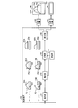
- FIG. 1-1 is a diagram of a configuration example 1 of the transmission apparatus according to the embodiment.
- the transmission apparatus 100 includes a storage unit 110, a dividing unit 120, and a distribution unit 130.
- the transmission apparatus 100 transmits a data flow to the opposite apparatus by link aggregation using a plurality of wireless links.
- the transmission apparatus 100 transmits a data flow by link aggregation using the aggregation links # 1 and # 2.
- Each of the aggregation links # 1 and # 2 is a radio link.
- a data flow is a group of packets identified by, for example, an input link (input port), destination or source MAC address, destination or source IP address, destination or source port number, upper layer type, etc. is there.
- the transfer devices 141 and 142 are transfer devices that transfer the traffic distributed from the transmission device 100 through the aggregation links # 1 and # 2, respectively.
- the transfer apparatuses 141 and 142 acquire and manage the states of the aggregation links # 1 and # 2, respectively.
- the states of the aggregation links # 1 and # 2 are transmission rates that vary depending on, for example, the radio states of the aggregation links # 1 and # 2.
- the transfer apparatuses 141 and 142 acquire parameters such as the guaranteed rate and peak rate of each data flow.
- the transfer devices 141 and 142 identify the data packets of the data flows 1 and 2 for the input packet from the transmission device 100, and transfer traffic from the size of the data packet and the elapsed time from the previous transmission. Monitor volume. Further, when the traffic of the input data flows 1 and 2 exceeds the peak rate, the transfer devices 141 and 142 transmit each traffic while performing traffic shaping.
- the traffic 101 is data flow traffic transmitted by the transmission apparatus 100.
- the horizontal direction indicates time
- the vertical direction indicates the traffic amount (rate).
- the guaranteed rate A1 indicates the guaranteed rate to be guaranteed in the data flow transmitted by the transmission apparatus 100.
- the traffic 101 has a traffic amount exceeding the guaranteed rate A1.
- the storage unit 110 stores the guaranteed rate A1 of the data flow transmitted by the transmission apparatus 100.
- the dividing unit 120 and the allocating unit 130 perform output scheduling of data flow traffic based on the traffic amount of the data flow transmitted by the transmission apparatus 100 and the transmission speeds of the aggregation links # 1 and # 2.
- the information on the respective transmission rates of the aggregation links # 1 and # 2 can be acquired by notification from the transfer apparatuses 141 and 142 or an inquiry from the transmission apparatus 100 to the transfer apparatuses 141 and 142.
- the dividing unit 120 acquires the guaranteed rate A1 stored in the storage unit 110. Then, the dividing unit 120 divides the traffic 101 into guaranteed traffic 101a (first traffic) corresponding to the guaranteed rate A1 and excess traffic 101b (second traffic) exceeding the guaranteed rate A1. The dividing unit 120 outputs the divided guaranteed traffic 101a and excess traffic 101b to the distributing unit 130.
- the distributing unit 130 distributes the guaranteed traffic 101a output from the dividing unit 120 to at least one of the aggregation links # 1 and # 2.
- the distribution unit 130 distributes the guaranteed traffic 101a with priority over the excess traffic 101b.
- the allocating unit 130 distributes the excess traffic 101b output from the dividing unit 120 to the free bands of the aggregation links # 1 and # 2. As described above, the allocating unit 130 divides the excess traffic 101b from the guaranteed traffic 101a and distributes it to the free bandwidths of the aggregation links # 1 and # 2. Thereby, the excess traffic 101b can be transmitted using the free bandwidth of the aggregation links # 1 and # 2, and the throughput can be improved.
- the distributing unit 130 distributes the guaranteed traffic 101a to the aggregation link # 1.
- the distribution unit 130 distributes the excess traffic 101b to the aggregation link # 2. Thereby, the delay and discard of the excess traffic 101b can be avoided, and the throughput can be improved.
- the distribution unit 130 outputs the traffic distributed to the aggregation link # 1 to the transfer device 141, and outputs the traffic distributed to the aggregation link # 2 to the transfer device 142. As a result, the traffic distributed to the aggregation link # 1 in the data flow is transmitted by the aggregation link # 1. Further, traffic distributed to the aggregation link # 2 in the data flow is transmitted by the aggregation link # 2.
- FIG. 1-2 is a diagram of a configuration example 2 of the transmission apparatus according to the embodiment. 1-2, parts similar to those depicted in FIG. 1-1 are given the same reference numerals and description thereof is omitted.
- the transmission apparatus 100 may transmit a plurality of data flows using the aggregation links # 1 and # 2.
- the transmission apparatus 100 may include an identification unit 160 in addition to the configuration illustrated in FIG. 1-1.
- the transmission apparatus 100 transmits data flows 1 and 2.
- Each data flow transmitted by the transmission device 100 is input to the identification unit 160.
- the identification unit 160 identifies whether the input data flow is the data flow 1 or 2.
- the traffic of the data flows 1 and 2 is defined as traffics 102 and 103, respectively.
- Guaranteed rates A2 and A3 are guaranteed rates for data flows 1 and 2, respectively.
- the dividing unit 120 and the distributing unit 130 perform traffic output scheduling for each of the data flows 1 and 2 identified by the identifying unit 160 while monitoring the traffic amount.
- the dividing unit 120 divides each traffic of the data flows 1 and 2 output from the identifying unit 160 into guaranteed traffic and excess traffic. Specifically, the dividing unit 120 divides the traffic 102 into guaranteed traffic 102a corresponding to the guaranteed rate A2 and excess traffic 102b exceeding the guaranteed rate A2. Further, the dividing unit 120 divides the traffic 103 into the guaranteed traffic 103a corresponding to the guaranteed rate A3 and the excess traffic 103b exceeding the guaranteed rate A3.
- the distributing unit 130 distributes the guaranteed traffics 102a and 103a divided by the dividing unit 120 to at least one of the aggregation links # 1 and # 2.
- the distribution unit 130 distributes the guaranteed traffic 102a and 103a with priority over the excess traffic 102b and 103b.
- the distribution unit 130 distributes the guaranteed traffic 102a to the aggregation link # 1, and distributes the guaranteed traffic 103a to the aggregation link # 2.
- the distribution unit 130 distributes the excess traffic 102b and 103b to the free bandwidth of the aggregation link # 2.
- the excess traffic 102b is illustrated as the traffic amount accumulated with respect to the guaranteed traffic 103a and the excess traffic 103b.
- the distributing unit 130 distributes the guaranteed traffic 102a to the aggregation link # 1 associated with the data flow 1. In addition, the distribution unit 130 distributes the guaranteed traffic 103a to the aggregation link # 2 associated with the data flow 2.
- the allocating unit 130 subtracts the rate 50 [Mbps] of the guaranteed traffic 102a allocated to the aggregation link # 1 from the transmission rate 50 [Mbps] of the aggregation link # 1 to the free bandwidth of the aggregation link # 1. To calculate.
- the free bandwidth of the aggregation link # 1 is 0 [Mbps].
- the allocating unit 130 subtracts the rate 50 [Mbps] of the guaranteed traffic 103a allocated to the aggregation link # 2 from the transmission rate 200 [Mbps] of the aggregation link # 2 for the free bandwidth of the aggregation link # 2.
- the free bandwidth of aggregation link # 2 is 150 [Mbps].
- the aggregation link # 1 is in a state where the band is used up only by the guaranteed traffic 102a of the data flow 1. Therefore, the allocating unit 130 distributes the excess traffic 102b of the data flow 1 and the excess traffic 103b of the data flow 2 to the aggregation link # 2.
- the guaranteed rates A2 and A3 of the data flows 1 and 2 are set within a range below the minimum transmission speed of the aggregation links # 1 and # 2, respectively.
- the minimum transmission rate of aggregation links # 1 and # 2 is 50 [Mbps].
- the guaranteed traffic 101a of the data flow 1 of 50 [Mbps] distributed to the aggregation link # 1 is all transmitted by the aggregation link # 1 because the transmission speed of the aggregation link # 1 does not become 50 [Mbps] or less.
- the guaranteed traffic 103a and the excess traffic 102b and 103b distributed to the aggregation link # 2 are all transmitted through the aggregation link # 2 when the sum of the excess traffic 102b and 103b is 150 [Mbps] or less.
- the transfer apparatus 142 uses all the bandwidth of the aggregation link # 2 for each traffic of the data flow 2 and uses the bandwidth for the data flow 2. Make a guarantee. At this time, all the traffic of the data flow 1 (excess traffic 102b) and the excess traffic 103b of the data flow 2 are retained in the buffer of the transfer device 142, or are discarded when there is no free space in the buffer.
- the transmission apparatus 100 may assign a sequence number for each data flow to the input packet, for example.
- a transmission apparatus (not shown) on the reception side via link aggregation performs the data packet order alignment based on the sequence number for each data flow and then toward another apparatus that is the destination of the data packet. Output.
- FIG. 1-3 is a diagram of a configuration example 3 of the transmission apparatus according to the embodiment. 1-3, parts similar to those depicted in FIG. 1-2 are given the same reference numerals and explanation thereof is omitted.
- the transmission apparatus 100 may include a shaping unit 170 in addition to the configuration illustrated in FIG. 1-2.
- Peak rates P2 and P3 indicate peak rates set in the data flows 1 and 2, respectively.
- the storage unit 110 (second storage unit) stores the peak rates P2 and P3 of the data flows 1 and 2.
- the shaping unit 170 acquires the peak rates P2 and P3 stored in the storage unit 110. Then, the shaping unit 170 performs traffic shaping for shaping the data flows 1 and 2 identified by the identification unit 160 so that the transmission rates do not exceed the peak rates P2 and P3, respectively.
- the shaping unit 170 performs traffic shaping by adjusting the output interval of data packets, for example.
- the dividing unit 120 divides each traffic of the data flows 1 and 2 subjected to traffic shaping by the shaping unit 170 into guaranteed traffic 102a and 103a and excess traffic 102b and 103b, respectively.
- the peak rates P2 and P3 are 100 [Mbps], respectively.
- the traffics 102 and 103 of the data flows 1 and 2 input to the transmission apparatus 100 include bursts exceeding the peak rates P2 and P3, respectively.
- the dividing unit 120 and the distributing unit 130 distribute traffic to the aggregation links # 1 and # 2 after the shaping unit 170 performs traffic shaping at the peak rates P2 and P3.
- the shaping unit 170 performs traffic shaping at the peak rates P2 and P3.
- the transfer device 141 For the data flow 1 associated with the aggregation link # 1, the transfer device 141 performs bandwidth guarantee by the guarantee rate A2 and control of the peak rate P2. Further, for the data flow 2 that is not associated with the aggregation link # 1, the transfer device 141 uses the rate obtained by subtracting the guaranteed rate A3 from the peak rate P3, that is, the rate when all the excess traffic 103b is distributed as the peak rate. Control.
- the transfer device 142 For the data flow 2 associated with the aggregation link # 2, the transfer device 142 performs bandwidth guarantee by the guarantee rate A3 and control of the peak rate P3. For the data flow 1 that is not associated with the aggregation link # 2, the transfer apparatus 142 uses the rate obtained by subtracting the guaranteed rate A2 from the peak rate P2, that is, the rate when all excess traffic 102b is distributed, as the peak rate. Control. As a result, the bandwidth of each data flow can be guaranteed and the traffic volume can be suppressed below the peak rate.
- FIG. 2 is a diagram illustrating a first distribution example of traffic.
- the transmission speeds of aggregation links # 1 and # 2 are both 100 [Mbps].
- the guaranteed rates A2 and A3 of the data flows 1 and 2 are both 50 [Mbps].
- the peak rates P2 and P3 of the data flows 1 and 2 are both 100 [Mbps].
- the traffics 102 and 103 of the data flows 1 and 2 are both 100 [Mbps].
- the guaranteed traffics 102a and 103a are allocated to the aggregation links # 1 and # 2, respectively, the free bandwidths of the aggregation links # 1 and # 2 are 50 [Mbps]. Then, it is assumed that the excess traffic 102b and 103b of the data flows 1 and 2 are respectively distributed to the aggregation links # 1 and # 2 at a ratio of 1: 1.
- the distribution unit 130 distributes 25 [Mbps], which is half of 50 [Mbps] of the excess traffic 102b, to the aggregation link # 1 as the excess traffic 102b1. Also, the distribution unit 130 distributes the remaining half of 25 [Mbps] to the aggregation link # 2 as excess traffic 102b2.
- the distribution unit 130 distributes 25 [Mbps], which is half of 50 [Mbps] of the excess traffic 103b, to the aggregation link # 1 as the excess traffic 103b1. In addition, the distribution unit 130 distributes the remaining half of 25 [Mbps] to the aggregation link # 2 as the excess traffic 103b2.
- FIG. 3 is a diagram showing a second distribution example of traffic.
- FIG. 3 shows an example of traffic distribution when the transmission rates of aggregation links # 1 and # 2 are 100 [Mbps] and 200 [Mbps] in FIG.
- the guaranteed traffics 102a and 103a are distributed to the aggregation links # 1 and # 2, respectively, the free bandwidths of the aggregation links # 1 and # 2 are 50 [Mbps] and 150 [Mbps], respectively.
- the excess traffic 102b and 103b of the data flows 1 and 2 is distributed to the aggregation links # 1 and # 2 at a ratio of 1: 3, respectively.
- the distribution unit 130 distributes 1/4 [12.5 [Mbps] of 50 [Mbps] of the excess traffic 102b to the aggregation link # 1 as the excess traffic 102b1.
- the distribution unit 130 distributes the remaining 3/4 of 37.5 [Mbps] to the aggregation link # 2 as the excess traffic 102b2.
- the distribution unit 130 distributes 1/4 [12.5 [Mbps] of 50 [Mbps] of the excess traffic 103b to the aggregation link # 1 as the excess traffic 103b1.
- the distribution unit 130 distributes the remaining 3/4 of 37.5 [Mbps] to the aggregation link # 2 as the excess traffic 103b2.
- FIG. 4 is a diagram showing a third example of traffic distribution.
- FIG. 4 shows a case where the guaranteed rate A2 of the data flow 1 is larger than the lowest transmission rate of the aggregation link # 1 in FIG. Assume that the transmission speeds of aggregation links # 1 and # 2 are 50 [Mbps] and 200 [Mbps], respectively. For simplicity, it is assumed that the input traffic is only the data flow 1. Further, it is assumed that the guaranteed rate A2 and the peak rate P2 are 100 [Mbps] and 200 [Mbps], respectively.
- the aggregation link # 1 is in a state of being lowered to the lowest transmission rate.
- the guaranteed rate A2 of the data flow 1 is larger than the minimum transmission rate of the aggregation link # 1
- the guaranteed traffic 102a of the data flow 1 is distributed to the aggregation links # 1 and # 2 to guarantee the bandwidth. Do.
- the distribution unit 130 distributes and distributes 100 [Mbps] guaranteed traffic 102a to the aggregation links # 1 and # 2 as 50 [Mbps] as the guaranteed traffic 102a1 and 102a2, respectively.
- the distribution unit 130 distributes the excess traffic 102b according to the free bandwidth of the aggregation links # 1 and # 2 as in the case of FIG. Specifically, since the vacant bandwidth of the aggregation link # 1 is 0 [Mbps], the distribution unit 130 distributes the excess traffic 102b of 100 [Mbps] to the aggregation link # 2.
- the guaranteed rate set in the transfer apparatuses 141 and 142 is, for example, 50 [Mbps] which is the respective guaranteed distribution rate.
- the peak rate set in the transfer apparatuses 141 and 142 is, for example, 150 [Mbps], which is a rate when the distribution guaranteed rate and all excess traffic are distributed.
- the guaranteed traffics 102a1 and 102a2 may be 40 [Mbps], respectively, or 50 [Mbps] and 30 [Mbps], respectively.
- the guaranteed rate A2 of the data flow 1 is 150 [Mbps]
- a transfer device is added to form three aggregation links, and the guaranteed traffic 102a is divided into three aggregation links by 50 [Mbps] each. You may sort it into.
- FIG. 5 is a diagram showing a distribution example 4 of each traffic.
- FIG. 5 shows an example of traffic distribution when the transmission rates of aggregation links # 1 and # 2 are 100 [Mbps] and 200 [Mbps] in the state of FIG. In this case, the free bands of the aggregation links # 1 and # 2 are 50 [Mbps] and 150 [Mbps], respectively.
- the distribution unit 130 distributes the guaranteed traffic 102a to the aggregation links # 1 and # 2 as the guaranteed traffic 102a1 and 102a2 as in the case of FIG. Further, the distribution unit 130 distributes the excess traffic 102b of the data flow 1 to the aggregation links # 1 and # 2 at a ratio of 1: 3. Specifically, the distribution unit 130 distributes 1/4 [25 Mbps] of the excess traffic 102b of 100 [Mbps] in the data flow 1 to the aggregation link # 1 as the excess traffic 102b1. In addition, the distribution unit 130 distributes the remaining 3/4 of 75 [Mbps] to the excess traffic 102b2 aggregation link # 2.
- FIG. 6A is a diagram illustrating a specific example of the transmission apparatus.
- a transmission apparatus 600 illustrated in FIG. 6A is a specific example of the transmission apparatus 100 illustrated in FIGS. 1-1 to 1-3.
- the transmission apparatus 600 includes a transfer processing unit 610 and a line IF unit 620.
- the line IF unit 620 is a communication interface that accommodates each link connected to the transmission apparatus 600.
- the transmission apparatus 600 is connected to other apparatuses such as a radio base station and a server through one or more links via the line IF unit 620. Further, the transmission device 600 is connected to the opposite transmission device via the line IF unit 620 by n (n ⁇ 2) aggregation links # 1 to #n.
- n (n ⁇ 2) aggregation links # 1 to #n are accommodated by one line IF unit 620, but each link may be accommodated by a plurality of line IF units.
- the transfer processing unit 610 can be realized by an arithmetic circuit such as a DSP (Digital Signal Processor) or an FPGA (Field Programmable Gate Array).
- the transfer processing unit 610 includes an identification unit 611, a monitoring unit 612, a management unit 613, a storage unit 614, a scheduler 615, a transmission processing unit 616, and a reception processing unit 617.
- the identification unit 160 shown in FIGS. 1-2 and 1-3 can be realized by the identification unit 611, for example.
- the identification unit 611 identifies a data flow for a packet received from another device via the link and line IF unit 620.
- the data flow identification represents, for example, an input link (input port), a destination or transmission source MAC address, a destination or transmission source IP address, a destination or transmission source port number, a higher layer type, and other data types. This can be done based on an identifier or the like.
- the monitoring unit 612 monitors the amount of traffic transferred for each data flow identified by the identifying unit 611 based on the packet size and the transmission time.
- the traffic volume is, for example, the data volume per unit time.
- the monitoring unit 612 monitors the traffic amount by acquiring the amount of data stored in the buffer of traffic to be transferred.
- the management unit 613 acquires the transmission speeds of the aggregation links # 1 to #n.
- the transmission rates of aggregation links # 1 to #n are, for example, the transmission rates of the wireless communication sections included in aggregation links # 1 to #n.
- the transmission speed in the wireless communication section changes due to, for example, a change in radio wave state in the wireless communication section or switching of the modulation method.
- the management unit 613 acquires the transmission rate of the aggregation links # 1 to #n from each transfer device that terminates the wireless communication section included in the aggregation links # 1 to #n.
- the storage unit 110 shown in FIGS. 1-1 to 1-3 can be realized by the storage unit 614, for example.
- the storage unit 614 stores parameters such as guaranteed rates and peak rates for data flows, information on predetermined aggregation links to which traffic for the guaranteed rates is allocated (see, for example, FIGS. 7-1 to 7-3). ).
- the scheduler 615 distributes data packets (traffic) to each aggregation link based on the traffic amount of each data flow monitored by the monitoring unit 612 and the transmission speed of each aggregation link managed by the management unit 613. .
- the transmission processing unit 616 assigns a sequence number to the data packet transmitted from the transmission device 600 in order to guarantee the order of the data packet. If the sequence number is not required without performing the order guarantee, the transmission processing unit 616 may be omitted.
- the reception processing unit 617 performs data packet order alignment processing based on the sequence number assigned to the data packet received by the transmission apparatus 600. Note that the reception processing unit 617 may be omitted when the order alignment processing is not required without performing the order guarantee.
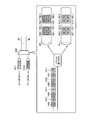
- FIG. 6B is a diagram of an example of each transmission device facing each other.
- Each of transmission apparatus 600A (first transmission apparatus) and transmission apparatus 600B (second transmission apparatus) shown in FIG. 6-2 has the same configuration as transmission apparatus 600 shown in FIG. As shown in FIG. 6B, transmission apparatuses 600A and 600B are connected to face each other.
- the links between the transmission apparatuses 600A and 600B include aggregation links # 1 to #n that are wireless communication sections.
- the transfer devices 631 to 63n are termination devices on the transmission device 600A side of the aggregation links # 1 to #n.
- the transfer devices 641 to 64n are termination devices on the transmission device 600B side of the aggregation links # 1 to #n.
- a data packet from another device 1 connected to the transmission device 600A is input from the link 1, and is transmitted to any of the transfer devices 631 to 63n via the line IF unit 620 and the transfer processing unit 610 of the transmission device 600A. Is output. Transfer devices 631 to 63n transmit the data packets output from transmission device 600A to transfer devices 641 to 64n, respectively.
- the data packet transmitted to the transfer devices 641 to 64n is input to the transmission device 600B.
- the data packet input to the transmission device 600B is output from the link 2 to another device 2 via the transfer processing unit 610 and the line IF unit 620 of the transmission device 600B.
- the flow of the data packet from the other device 1 to the other device 2 has been described, but the flow of the data packet from the other device 2 to the other device 1 is similarly performed by the aggregation links # 1 to #n. Is transmitted.
- FIG. 7A is a diagram of an example 1 of information stored in the storage unit.
- a table 710 shown in FIG. 7-1 is stored in the storage unit 614 (corresponding information storage unit) shown in FIG.
- the identification information, the guaranteed rate [Mbps], and the guaranteed traffic transfer link are associated with each of the data flows 1 and 2.
- the identification information in the table 710 is information for identifying the data flow.
- the input ports 1 and 2 are associated with the data flows 1 and 2, respectively.
- Each of the input ports 1 and 2 is an input port to which a data flow from another device is input in the line IF unit 620.
- the identification unit 611 identifies the data flow based on the input port to which the data flow is input and the table 710.
- the information for identifying the data flow is not limited to the input port, but information such as a source MAC address, a destination MAC address, a VLAN-ID, a source IP address, a destination IP address, or a combination of these information It may be.
- the guaranteed rate in the table 710 is the guaranteed rate set in the data flow.
- the scheduler 615 acquires the guaranteed rates of the data flows 1 and 2 from the table 710.
- the guaranteed traffic transfer link in the table 710 is an aggregation link that distributes the guaranteed traffic of the data flows 1 and 2.
- aggregation links # 1 and # 2 are associated with data flows 1 and 2, respectively.
- the scheduler 615 distributes the guaranteed traffic 102a of the data flow 1 to the aggregation link # 1, and distributes the guaranteed traffic 103a of the data flow 2 to the aggregation link # 2.
- FIG. 7-2 is a diagram of an example 2 of information stored in the storage unit.
- the storage unit 614 illustrated in FIG. 6A may store a table 710 illustrated in FIG. 7B.
- the peak rate [Mbps] is associated with each of the data flows 1 and 2 in addition to the items shown in FIG.
- the peak rate [Mbps] in the table 710 is a peak rate set for the data flow.
- the scheduler 615 acquires peak rates P2 and P3 of the data flows 1 and 2 from the table 710.
- FIG. 7-3 is a diagram of an example 3 of information stored in the storage unit.
- the storage unit 614 may store a table 710 shown in FIG. 7-3.
- the aggregation links # 1 and # 2 are associated with the data flow 1 as guaranteed traffic transfer links, and the distribution links are guaranteed to the aggregation links # 1 and # 2, respectively.
- a rate is associated.
- the scheduler 615 distributes the guaranteed traffic 102a of the data flow 1 to the aggregation links # 1 and # 2 by 50 [Mbps] based on the table 710 shown in FIG.
- FIG. 8 is a flowchart showing packet reception processing by the transmission apparatus. Each time the transmission apparatus 600 receives a packet to be transferred by link aggregation via the line IF unit 620, for example, the transmission apparatus 600 performs the following processing. First, the identification unit 611 identifies the data flow of the received packet (step S801).
- the transmission processing unit 616 assigns a sequence number corresponding to the data flow identified in step S801 to the received packet (step S802), and ends a series of processing. However, if the order is not guaranteed, step S802 need not be executed.
- the packet processed in each step of FIG. 8 is stored in the buffer of the transmission apparatus 600 as a transmission waiting packet for each data flow.
- FIG. 9 is a flowchart showing packet transmission processing by the transmission apparatus.
- the transmission apparatus 600 repeatedly executes, for example, the following steps for each data flow in a state where the transmission waiting packet is stored in the buffer by the steps shown in FIG.
- the scheduler 615 determines whether or not the transmission waiting packet stored in the buffer can be read as a guarantee packet (guaranteed traffic) or an excess packet (excess traffic) (step S901).
- the determination method in step S901 will be described later (see, for example, FIGS. 10 and 11).
- step S901 when the transmission waiting packet cannot be read (step S901: No), the scheduler 615 ends a series of processes. If the transmission waiting packet can be read (step S901: Yes), the scheduler 615 determines whether or not the transmission packet that can be read can be read as a guarantee packet (step S902).
- step S902 when the packet waiting for transmission can be read as a guarantee packet (step S902: Yes), the scheduler 615 acquires a guarantee packet transfer link of the target data flow from the table 710 (step S903). Next, the scheduler 615 transmits a readable packet to the guaranteed packet transfer link acquired in step S903 (step S904), and the series of processing ends.
- step S902 if the transmission waiting packet can be read as an excess packet instead of a guarantee packet (step S902: No), a link to which the excess packet is distributed is determined (step S905).
- the determination method in step S905 will be described later (see, for example, FIGS. 12 to 19).
- the scheduler 615 transmits a transmission waiting packet to the distribution destination link determined in step S905 (step S906), and the series of processing ends.
- FIG. 10 is a diagram illustrating an example of a read determination process performed by the transmission apparatus.
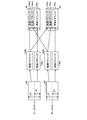
- the transmission apparatus 600 manages transmission waiting packets stored in the buffer for each of the data flows 1 to m.
- the monitoring unit 612 includes a token bucket counter 1020 for a guaranteed rate and a token bucket counter 1030 for a peak rate for each of the transmission queues 1011 to 101m of the data flows 1 to m.
- the scheduler 615 uses the guaranteed-rate token bucket counter 1020 and the peak-rate token bucket counter 1030 to determine whether the packet stored in the buffer can be read and whether it is a guaranteed packet or an excess packet. .
- the guaranteed rate token bucket counter 1020 is periodically added with a guaranteed rate token (unit: for example, bit) corresponding to the size of the guaranteed rate.
- the peak rate token bucket counter 1030 is periodically added with a peak rate token (for example, bit) corresponding to the magnitude of the peak rate.
- the token bucket counter 1020 for the guaranteed rate and the token bucket counter 1030 for the peak rate have an upper limit value, and are not added beyond the upper limit value.
- the upper limit values of the token bucket counter 1020 for guaranteed rates and the token bucket counter 1030 for peak rates correspond to the data size that can be read continuously when the transmission queue is accumulated. Note that the peak rate token is set to a larger value than the guaranteed rate token.
- the guaranteed rate of data flow 1 is 50 [Mbps].
- the guaranteed rate token is set to be added to the guaranteed rate token bucket counter 1020 by 50 [kbit].
- the upper limit value of the token bucket counter 1020 for the guaranteed rate is set to 500 [kbit].
- the peak rate of data flow 1 is 100 [Mbps].
- the peak rate token is set to be added to the peak rate token bucket counter 1030 by 100 [kbit].
- the upper limit value of the token bucket counter 1030 for peak rate is set to 1000 [kbit].
- the scheduler 615 reads the packet waiting for transmission as the guaranteed packet.
- the scheduler 615 reads the transmission waiting packet as an excess packet.
- the scheduler 615 distributes and transmits the transmission waiting packet read as the guarantee packet or the excess packet to at least one of the aggregation links # 1 to #n via the switch 1040.
- the transmission waiting packet in the buffer stays until tokens are accumulated in each token bucket counter.
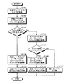
- FIG. 11 is a flowchart illustrating an example of a read determination process performed by the transmission apparatus.
- the transmission apparatus 600 executes each step shown in FIG. 11, for example, to determine whether or not the transmission waiting packet stored in the buffer can be read as a guarantee packet or an excess packet. To do.
- each data flow may be processed one packet at a time in round robin, or the next data flow may be sequentially processed after all the transmission waiting packets of a certain data flow are processed.
- the scheduler 615 obtains the size of a transmission waiting packet that can be read (step S1101). Next, the scheduler 615 acquires the value of the token bucket counter 1020 for the guaranteed rate of the target data flow (step S1102). Next, the scheduler 615 determines whether or not the counter value acquired in step S1102 is greater than or equal to the packet size acquired in step S1101 (step S1103).
- step S1103 when the counter value is equal to or larger than the packet size (step S1103: Yes), the scheduler 615 proceeds to step S1104. That is, the scheduler 615 subtracts tokens for the packet size acquired in step S1101 from the token bucket counters 1020 and 1030 (step S1104). Next, the scheduler 615 determines that the packet waiting for transmission can be read out as a guarantee packet (step S1105), and ends the series of processing.
- step S1103 when the counter value is not equal to or larger than the packet size (step S1103: No), the scheduler 615 acquires the counter value of the token bucket counter 1030 for the peak rate of the target data flow (step S1106). Next, the scheduler 615 determines whether or not the counter value acquired in step S1106 is greater than or equal to the packet size acquired in step S1101 (step S1107).
- step S1107 when the counter value is equal to or larger than the packet size (step S1107: Yes), the scheduler 615 proceeds to step S1108. That is, the scheduler 615 subtracts tokens for the packet size acquired in step S1101 from the token bucket counter 1030 for peak rate (step S1108). Next, the scheduler 615 determines that the transmission waiting packet can be read as an excess packet (step S1109), and ends a series of processing.
- step S1107 when the counter value is not equal to or larger than the packet size (step S1107: No), the scheduler 615 determines that the transmission waiting packet cannot be read (step S1110), and ends the series of processes.
- packets corresponding to the guaranteed rate can be transmitted as guaranteed packets, and packets corresponding to the excess exceeding the guaranteed rate can be transmitted as excess packets with the peak rate as the upper limit.
- FIG. 12 is a flowchart (part 1) illustrating an example 1 of excess packet distribution processing.
- the scheduler 615 determines the WRR pattern (WRR pattern) by executing the following steps when, for example, a change in the transmission rate of each aggregation link, addition or deletion of a data flow, or a change in guaranteed rate occurs. To do.
- the scheduler 615 acquires the transmission rate of each aggregation link from the management unit 613 (step S1201). Next, the scheduler 615 acquires the guaranteed rate and guaranteed traffic transfer link of each data flow from the table 710 (see FIGS. 7-1 to 7-3) stored in the storage unit 614 (step S1202).
- the scheduler 615 calculates the free bandwidth of each aggregation link based on each transmission rate acquired in step S1201 and each guaranteed rate acquired in step S1202 (step S1203).
- the scheduler 615 determines a WRR pattern based on the ratio of the free bandwidth of each aggregation link calculated in step S1203 (step S1204), and ends a series of processing.
- the scheduler 615 has two aggregation links # 1 and # 2, and when the ratio of the free bandwidths of the aggregation links # 1 and # 2 is 1: 1, the aggregation links # 1 and # 2 The order is a WRR pattern. Further, the scheduler 615 uses the WRR pattern in the order of the aggregation links # 1, # 2, # 2, and # 2 when the ratio of the free bandwidth is 1: 3. In addition, the scheduler 615 excludes the aggregation link whose free bandwidth is 0 from the target to which excess packets are distributed.
- FIG. 13 is a flowchart (part 2) illustrating an example 1 of excess packet distribution processing.
- the scheduler 615 executes the following steps. First, the scheduler 615 acquires a WRR pattern determined in step S1204 shown in FIG. 12 and a pointer indicating the position of the current WRR (step S1301).
- the scheduler 615 acquires the aggregation link indicated by the pointer in the WRR pattern acquired in step S1301 (step S1302). For example, when the ratio of the free bandwidth of each aggregation link is 1: 1, the WRR pattern is aggregation links # 1 and # 2, and the pointer indicates the head of the WRR pattern, the aggregation link # 1 is acquired.
- the scheduler 615 increments the WRR pointer for the next reading (step S1303), and ends the series of processing.
- the pointer indicates the head of the WRR pattern
- the reference destination of the pointer incremented in step S1303 is changed to the aggregation link # 2.
- FIG. 14 is a diagram showing a first example of distribution by the determination process shown in FIGS. For example, as a result of each step shown in FIG. 12, it is assumed that the ratio of the free bandwidth of the aggregation links # 1 and # 2 is 1: 1, and the WRR pattern is in the order of the aggregation links # 1 and # 2.
- the guarantee packets 1411 and 1421 indicate the guarantee packets of the data flows 1 and 2, respectively.
- Excess packets 1412 and 1422 indicate the excess packets of the data flows 1 and 2, respectively.
- the guaranteed packets 1411 and 1421 are distributed to the aggregation links # 1 and # 2 associated with the data flows 1 and 2, respectively.
- the first excess packet 1412 in the data flow 1 is distributed to the aggregation link # 1.
- the first excess packet 1422 of the data flow 2 is distributed to the aggregation link # 2.
- the second excess packet 1412 of the data flow 1 is distributed to the aggregation link # 1.
- the second excess packet 1422 of the data flow 2 is distributed to the aggregation link # 2.
- FIG. 15 is a diagram showing a distribution example 2 by the determination process shown in FIGS. 12 and 13.
- the same parts as those shown in FIG. 14 are denoted by the same reference numerals, and description thereof is omitted.
- the ratio of the free bandwidth of the aggregation links # 1, # 2 is 1: 3, and the WRR pattern is in the order of the aggregation links # 1, # 2, # 2, # 2.
- the guaranteed packets 1411 and 1421 are distributed to the aggregation links # 1 and # 2 associated with the data flows 1 and 2, respectively.
- the first excess packet 1412 in the data flow 1 is distributed to the aggregation link # 1.
- the first excess packet 1422 of the data flow 2 is distributed to the aggregation link # 2.
- the second excess packet 1412 of the data flow 1 is distributed to the aggregation link # 2.
- the second excess packet 1422 of the data flow 2 is distributed to the aggregation link # 2.
- excess packets can be distributed according to the size of the free bandwidth of each aggregation link.
- the order of the WRR is not fixed every time, but the start position is shifted for each round. Therefore, in order to manage the start position of the WRR, a pointer for the round start position is also used in addition to the WRR pointer.
- the scheduler 615 determines a WRR pattern by each step shown in FIG.
- FIG. 16 is a flowchart showing an example 2 of excess packet distribution processing.
- the scheduler 615 executes the following steps. First, the scheduler 615 acquires the WRR pattern determined in step S1204 shown in FIG. 12 and a pointer indicating the position of the current WRR (step S1601).
- the scheduler 615 acquires the aggregation link indicated by the pointer in the WRR pattern acquired in step S1601 (step S1602). For example, when the ratio of the free bandwidth of each aggregation link is 1: 1 and the WRR pattern is aggregation links # 1 and # 2, the aggregation link # 1 is acquired when the pointer indicates the head of the WRR pattern. .
- the scheduler 615 determines whether or not the current round is completed (round is 1 round) (step S1603). If the current round has not ended (step S1603: NO), the scheduler 615 increments the WRR pointer for the next reading (step S1604), and ends the series of processes.
- step S1603 when the current round is completed (step S1603: Yes), the scheduler 615 increments the round start position pointer (step S1605). Thereby, the start position of WRR in the next round can be shifted.
- the ratio of the free bandwidth of each aggregation link is 1: 3, and the WRR pattern is the aggregation links # 1, # 2, # 2, and # 2.
- the reading order is aggregation links # 1, # 2, # 2, and # 2.
- the reading order is link aggregation links # 2, # 2, # 2, and # 1.
- the reading order is aggregation links # 2, # 2, # 1, and # 2.
- the reading order is aggregation links # 2, # 1, # 2, and # 2.
- the scheduler 615 sets the WRR pointer for the next round to the position of the round start position pointer incremented in step S1605 (step S1606), and ends the series of processing.
- FIG. 17 is a diagram showing a first example of distribution by the determination process shown in FIG. 17, parts that are the same as the parts shown in FIG. 14 are given the same reference numerals, and descriptions thereof will be omitted.
- the ratio of the free bandwidth of the aggregation links # 1 and # 2 is 1: 1, and the WRR pattern is in the order of the aggregation links # 1 and # 2.
- the guarantee packets 1411 and 1421 are distributed to the aggregation links # 1 and # 2 associated with the data flows 1 and 2, respectively.
- the first excess packet 1412 in the data flow 1 is distributed to the aggregation link # 1.
- the first excess packet 1422 of the data flow 2 is distributed to the aggregation link # 2.
- the second excess packet 1412 of the data flow 1 is distributed to the aggregation link # 2.
- the second excess packet 1422 in the data flow 2 is distributed to the aggregation link # 1.
- FIG. 18 is a diagram showing a distribution example 2 by the determination process shown in FIG. 18, parts that are the same as the parts shown in FIG. 17 are given the same reference numerals, and descriptions thereof will be omitted.
- the ratio of the free bandwidth of the aggregation links # 1, # 2 is 1: 3, and the WRR pattern is in the order of the aggregation links # 1, # 2, # 2, # 2.
- the guarantee packets 1411 and 1421 are distributed to the aggregation links # 1 and # 2 associated with the data flows 1 and 2, respectively.
- the first excess packet 1412 in the data flow 1 is distributed to the aggregation link # 1.
- the first excess packet 1422 of the data flow 2 is distributed to the aggregation link # 2.
- the second excess packet 1412 of the data flow 1 is distributed to the aggregation link # 2.
- the second excess packet 1422 of the data flow 2 is distributed to the aggregation link # 2.
- the third excess packet 1412 of the data flow 1 is distributed to the aggregation link # 2.
- the third excess packet 1422 of the data flow 2 is distributed to the aggregation link # 2.
- the fourth excess packet 1412 in the data flow 1 is distributed to the aggregation link # 2.
- the fourth excess packet 1422 in the data flow 2 is distributed to the aggregation link # 1.
- the fifth to eighth excess packets 1412 and 1422 of the data flows 1 and 2 described below are not shown in FIG.
- the fifth excess packet 1412 of the data flow 1 is distributed to the aggregation link # 2.
- the fifth excess packet 1422 in the data flow 2 is distributed to the aggregation link # 2.
- the sixth excess packet 1412 in the data flow 1 is distributed to the aggregation link # 1.
- the sixth excess packet 1422 in the data flow 2 is distributed to the aggregation link # 2.
- the seventh excess packet 1412 in the data flow 1 is distributed to the aggregation link # 2.
- the seventh excess packet 1422 of the data flow 2 is distributed to the aggregation link # 1.
- the eighth excess packet 1412 of the data flow 1 is distributed to the aggregation link # 2.
- the eighth excess packet 1422 of the data flow 2 is distributed to the aggregation link # 2.
- the sliding WRR it is possible to distribute excess packets according to the size of the free bandwidth of each aggregation link. Further, according to the sliding WRR, the excess packets of each data flow can be distributed more evenly without the excess packets of each data flow being biased to a specific link. For this reason, for example, when the transmission speed of the aggregation link decreases, the influence of delay and discard on each data flow becomes the same, and the fairness between the data flows can be improved.
- FIG. 19 is a flowchart showing an example 3 of excess packet distribution processing.
- the scheduler 615 executes the following steps. First, the scheduler 615 acquires the transmission rate of each aggregation link (step S1901). Next, the scheduler 615 obtains the guaranteed rate and guaranteed traffic transfer link for each data flow from the table 710 (see FIGS. 7-1 to 7-3) stored in the storage unit 614 (step S1902).
- the scheduler 615 acquires the amount of excess traffic of each aggregation link (step S1903). For example, when the scheduler 615 determines to read as an excess packet in step S1109 in FIG. 11, the size of the packet to be read is accumulated and stored as the transmission data amount. Then, the scheduler 615 can acquire the amount of excess traffic by converting the accumulated transmission data amount into the traffic amount per unit time.
- the scheduler 615 calculates the excess traffic usage rate of each aggregation link based on the amount of excess traffic of each aggregation link acquired in step S1903 (step S1904).
- the usage rate of excess traffic is the ratio of excess packet traffic in the free bandwidth.
- the transmission data amount per second is 10 [Mbit]
- the transmission traffic amount is 10 [Mbps].
- the transmission rate is 100 [Mbps]
- the total guaranteed rate of transmission is 50 [Mbps]
- the traffic amount of excess packets is 10 [Mbps].
- the scheduler 615 selects the aggregation link with the minimum excess traffic usage rate calculated in step S1904 as the excess traffic distribution destination link (step S1905), and ends the series of processes.
- the scheduler 615 distributes excess packets according to the size of the free bandwidth of each aggregation link. Note that the method of determining the distribution destination link is not limited to the examples shown in FIGS. 12 to 19, and other methods may be used.
- FIG. 20 is a diagram illustrating a first example of a transmission system to which the transmission apparatus is applied. 20, parts that are the same as the parts shown in FIG. 6-2 are given the same reference numerals, and descriptions thereof will be omitted.
- a radio transmission system 2000 shown in FIG. 20 includes a radio base station 2010, a transmission device 600A, transfer devices 631 to 63n, transfer devices 641 to 64n, a transmission device 600B, and a radio system core network 2020. Yes.
- the transmission apparatus 600A and the transmission apparatus 600B transfer each data flow transmitted and received between the radio base station 2010 and the radio system core network 2020 by link aggregation using the aggregation links # 1 to #n. As described above, the transmission apparatus 600A and the transmission apparatus 600B can be applied to a backhaul line portion between the radio base station 2010 and the radio system core network 2020 of the radio transmission system 2000.
- FIG. 21 is a diagram illustrating a second example of the transmission system to which the transmission device is applied.
- a transmission system 2100 shown in FIG. 21 includes a user base LAN 2110, a transmission device 600A, transfer devices 631 to 63n, transfer devices 641 to 64n, a transmission device 600B, and a wide area backbone 2120.
- the transmission device 600A and the transmission device 600B transfer each data flow transmitted and received between the user base LAN 2110 and the wide area backbone 2120 by link aggregation using the aggregation links # 1 to #n.
- the transmission device 600A and the transmission device 600B can be applied to the VPN connection link portion between the user base LAN 2110 and the wide area backbone 2120 of the transmission system 2100.
- traffic for the guaranteed rate out of the traffic is preferentially distributed to the radio links, and traffic exceeding the guaranteed rate is free in each radio link. Can be distributed to bands. Thereby, the throughput can be improved while guaranteeing the bandwidth.
- A1 to A3 Guaranteed rate P2 P3 Peak rate 101 to 103 Traffic 101a, 102a, 103a Guaranteed traffic 101b, 102b, 103b Excess traffic 631 to 63n Transfer device 641 to 64n Transfer device 1011 to 101m Transmission queue 1020, 1030 Token bucket counter 1040 Switch 1411, 1421 Guaranteed packet 1412, 1422 Excess packet 2000 Wireless transmission system 2010 Wireless base station 2020 Wireless system core network 2100 Transmission system 2110 User base LAN 2120 Wide-area backbone
Landscapes
- Engineering & Computer Science (AREA)
- Computer Networks & Wireless Communication (AREA)
- Signal Processing (AREA)
- Mobile Radio Communication Systems (AREA)
- Data Exchanges In Wide-Area Networks (AREA)
Abstract
La présente invention se rapporte à un dispositif de transmission (100) qui transmet un flux de données au moyen de liaisons d'agrégation (n° 1, n° 2). Le dispositif de transmission selon l'invention (100) comprend un module de stockage (110), un module de tri (120) et un module d'allocation (130). Le module de stockage (110) acquiert un taux de garantie (A1) devant être garanti dans le flux de données. Le module de tri (120) trie le trafic (101) du flux de données, en trafic de garantie (101a) pour une partie du taux de garantie (A1) acquis par le module de stockage (110), et en trafic en excédent (101b) pour une partie excédant le taux de garantie (A1). Le module d'allocation (130) alloue le trafic de garantie (101a) trié par le module de tri (120) dans au moins une des liaisons d'agrégation (n° 1, n° 2), au trafic en excédent (101b) de préférence. D'autre part, le module d'allocation (130) alloue le trafic en excédent (101b) à une bande vide des liaisons d'agrégation (n° 1, n° 2).
Priority Applications (4)
| Application Number | Priority Date | Filing Date | Title |
|---|---|---|---|
| EP11856137.2A EP2667662A4 (fr) | 2011-01-19 | 2011-01-19 | Dispositif de transmission, procédé de transmission et système de transmission |
| JP2012553503A JP5696726B2 (ja) | 2011-01-19 | 2011-01-19 | 伝送装置および伝送システム |
| PCT/JP2011/050892 WO2012098656A1 (fr) | 2011-01-19 | 2011-01-19 | Dispositif de transmission, procédé de transmission et système de transmission |
| US13/934,250 US9439102B2 (en) | 2011-01-19 | 2013-07-03 | Transmitting apparatus, transmission method, and transmission system |
Applications Claiming Priority (1)
| Application Number | Priority Date | Filing Date | Title |
|---|---|---|---|
| PCT/JP2011/050892 WO2012098656A1 (fr) | 2011-01-19 | 2011-01-19 | Dispositif de transmission, procédé de transmission et système de transmission |
Related Child Applications (1)
| Application Number | Title | Priority Date | Filing Date |
|---|---|---|---|
| US13/934,250 Continuation US9439102B2 (en) | 2011-01-19 | 2013-07-03 | Transmitting apparatus, transmission method, and transmission system |
Publications (1)
| Publication Number | Publication Date |
|---|---|
| WO2012098656A1 true WO2012098656A1 (fr) | 2012-07-26 |
Family
ID=46515308
Family Applications (1)
| Application Number | Title | Priority Date | Filing Date |
|---|---|---|---|
| PCT/JP2011/050892 Ceased WO2012098656A1 (fr) | 2011-01-19 | 2011-01-19 | Dispositif de transmission, procédé de transmission et système de transmission |
Country Status (4)
| Country | Link |
|---|---|
| US (1) | US9439102B2 (fr) |
| EP (1) | EP2667662A4 (fr) |
| JP (1) | JP5696726B2 (fr) |
| WO (1) | WO2012098656A1 (fr) |
Cited By (3)
| Publication number | Priority date | Publication date | Assignee | Title |
|---|---|---|---|---|
| JP2016010152A (ja) * | 2014-06-20 | 2016-01-18 | アップル インコーポレイテッド | アプリケーショントラフィックパターンに基づく物理データチャネルの選択 |
| JP2017060036A (ja) * | 2015-09-17 | 2017-03-23 | 日本電気株式会社 | 帯域制御装置、帯域制御方法及びプログラム |
| JP2017513314A (ja) * | 2014-03-10 | 2017-05-25 | 華為技術有限公司Huawei Technologies Co.,Ltd. | データ送信方法および通信装置 |
Families Citing this family (6)
| Publication number | Priority date | Publication date | Assignee | Title |
|---|---|---|---|---|
| US9807161B2 (en) * | 2013-09-16 | 2017-10-31 | Axis Ab | Distributed events in an access control system |
| CN103560974B (zh) * | 2013-10-25 | 2017-01-25 | 华为技术有限公司 | 一种令牌维护的方法和装置 |
| GB2540172B (en) * | 2015-07-08 | 2018-06-13 | Canon Kk | Method of load balancing in a multi-radio communication system |
| US10524278B2 (en) * | 2015-11-20 | 2019-12-31 | Qualcomm Incorporated | Scheduling and token bucket for communication co-existence |
| CN109218215B (zh) | 2017-06-29 | 2021-11-19 | 华为技术有限公司 | 一种报文传输的方法和网络设备 |
| JP7205530B2 (ja) | 2018-02-27 | 2023-01-17 | 日本電気株式会社 | 伝送装置、方法およびプログラム |
Citations (6)
| Publication number | Priority date | Publication date | Assignee | Title |
|---|---|---|---|---|
| JP2001285322A (ja) * | 2000-03-28 | 2001-10-12 | Fujitsu Ltd | Lan間通信装置及びこれを用いるlan間通信ネットワーク |
| JP2004080139A (ja) | 2002-08-12 | 2004-03-11 | Kddi R & D Laboratories Inc | マルチリンク通信システムにおけるパケットの順序制御方法 |
| JP2005252333A (ja) | 2004-03-01 | 2005-09-15 | Fujitsu Ltd | リンクアグリゲーションを用いた伝送制御システム |
| JP2007060494A (ja) | 2005-08-26 | 2007-03-08 | Nippon Telegr & Teleph Corp <Ntt> | ネットワークシステム、送信側振分装置、パケット通信方法、および、パケット通信プログラム |
| JP2008085692A (ja) * | 2006-09-28 | 2008-04-10 | Fujitsu Ltd | ベストエフォート帯域の割り当て方法及び装置 |
| WO2010125803A1 (fr) * | 2009-05-01 | 2010-11-04 | 日本電気株式会社 | Appareil de transmission sans fil et procede de transmission de trame mac |
Family Cites Families (5)
| Publication number | Priority date | Publication date | Assignee | Title |
|---|---|---|---|---|
| JP2001326675A (ja) * | 2000-05-15 | 2001-11-22 | Sony Corp | 情報処理装置および方法、並びに記録媒体 |
| US7965638B1 (en) * | 2006-05-22 | 2011-06-21 | Atrica Israel Ltd. | Policing machine incorporating randomization of rate threshold |
| US8625498B2 (en) * | 2007-01-22 | 2014-01-07 | Wi-Lan, Inc. | Tiling allocations for wireless communication |
| US8059540B2 (en) * | 2007-05-25 | 2011-11-15 | Futurewei Technologies, Inc. | Policy based and link utilization triggered congestion control |
| JP5577709B2 (ja) * | 2010-01-13 | 2014-08-27 | ソニー株式会社 | 基地局、端末装置、通信制御方法及び無線通信システム |
-
2011
- 2011-01-19 WO PCT/JP2011/050892 patent/WO2012098656A1/fr not_active Ceased
- 2011-01-19 EP EP11856137.2A patent/EP2667662A4/fr not_active Withdrawn
- 2011-01-19 JP JP2012553503A patent/JP5696726B2/ja not_active Expired - Fee Related
-
2013
- 2013-07-03 US US13/934,250 patent/US9439102B2/en not_active Expired - Fee Related
Patent Citations (6)
| Publication number | Priority date | Publication date | Assignee | Title |
|---|---|---|---|---|
| JP2001285322A (ja) * | 2000-03-28 | 2001-10-12 | Fujitsu Ltd | Lan間通信装置及びこれを用いるlan間通信ネットワーク |
| JP2004080139A (ja) | 2002-08-12 | 2004-03-11 | Kddi R & D Laboratories Inc | マルチリンク通信システムにおけるパケットの順序制御方法 |
| JP2005252333A (ja) | 2004-03-01 | 2005-09-15 | Fujitsu Ltd | リンクアグリゲーションを用いた伝送制御システム |
| JP2007060494A (ja) | 2005-08-26 | 2007-03-08 | Nippon Telegr & Teleph Corp <Ntt> | ネットワークシステム、送信側振分装置、パケット通信方法、および、パケット通信プログラム |
| JP2008085692A (ja) * | 2006-09-28 | 2008-04-10 | Fujitsu Ltd | ベストエフォート帯域の割り当て方法及び装置 |
| WO2010125803A1 (fr) * | 2009-05-01 | 2010-11-04 | 日本電気株式会社 | Appareil de transmission sans fil et procede de transmission de trame mac |
Non-Patent Citations (6)
| Title |
|---|
| "Amendment to Carrier Sense Multiple Access with Collision Detection (CSMA/CD) Access Method and Physical Layer Specifications", IEEE STD 802.3AD-2000, 30 March 2000 (2000-03-30) |
| "Introducing the Specifications of the MEF, An Overview of MEF 6.1 and MEF 10.1", METRO ETHERNET FORUM, 24 December 2010 (2010-12-24), pages 35 - 36 |
| "MEF Technical Specification MEF10.2, Ethernet Services Attributes Phase 2", METRO ETHERNET FORUM, 24 December 2010 (2010-12-24), pages 37 |
| HIGUCHI ET AL.: "Analysis of Optimal Traffic Distribution Control in a Heterogeneous Wireless Link Aggregation Scheme", IEICE TECHNICAL REPORT, vol. 109, no. 383, January 2010 (2010-01-01), pages 1 - 8 |
| ISHIZU; MURAKAMI; HARADA: "Link Aggregation Platform Enabling Flexible Traffic Control in a Cognitive Wireless Network", IEICE TECHNICAL COMMITTEE ON RCS, 27 August 2010 (2010-08-27) |
| See also references of EP2667662A4 |
Cited By (5)
| Publication number | Priority date | Publication date | Assignee | Title |
|---|---|---|---|---|
| JP2017513314A (ja) * | 2014-03-10 | 2017-05-25 | 華為技術有限公司Huawei Technologies Co.,Ltd. | データ送信方法および通信装置 |
| RU2650189C1 (ru) * | 2014-03-10 | 2018-04-11 | Хуавэй Текнолоджиз Ко., Лтд | Способ передачи данных и устройство связи |
| US10257846B2 (en) | 2014-03-10 | 2019-04-09 | Huawei Technologies Co., Ltd. | Data transmission method and communications device |
| JP2016010152A (ja) * | 2014-06-20 | 2016-01-18 | アップル インコーポレイテッド | アプリケーショントラフィックパターンに基づく物理データチャネルの選択 |
| JP2017060036A (ja) * | 2015-09-17 | 2017-03-23 | 日本電気株式会社 | 帯域制御装置、帯域制御方法及びプログラム |
Also Published As
| Publication number | Publication date |
|---|---|
| US9439102B2 (en) | 2016-09-06 |
| EP2667662A4 (fr) | 2016-05-18 |
| EP2667662A1 (fr) | 2013-11-27 |
| JPWO2012098656A1 (ja) | 2014-06-09 |
| JP5696726B2 (ja) | 2015-04-08 |
| US20130286842A1 (en) | 2013-10-31 |
Similar Documents
| Publication | Publication Date | Title |
|---|---|---|
| JP5696726B2 (ja) | 伝送装置および伝送システム | |
| JP4058326B2 (ja) | 無線基地局、制御装置、無線通信システム及び通信方法 | |
| KR101790631B1 (ko) | 원거리 통신 네트워크에서 데이터 패킷 스케줄링을 위한 방법 | |
| EP2761924B1 (fr) | Mise en forme de trafic à base de congestion pour mise en file d'attente distribuée dans des réseaux de communication à support partagé | |
| Liu et al. | Delay-optimized video traffic routing in software-defined interdatacenter networks | |
| EP3915297B1 (fr) | Procédés et appareil pour la décharge de paquets dans un réseau fronthaul | |
| EP3410641A1 (fr) | Procédé de régulation de trafic de réseau et dispositif de réseau associé | |
| US9940471B2 (en) | Virtual output queue authorization management method and device, and computer storage medium | |
| CN101808324B (zh) | 无线Mesh网络MAC层架构设计 | |
| Taha et al. | Two-level scheduling scheme for integrated 4G-WLAN network | |
| Jain et al. | Bandwidth allocation based on traffic load and interference in IEEE 802.16 mesh networks | |
| JP2007306206A (ja) | 通信システム | |
| CN105227491B (zh) | 一种配用电无线接入网中的资源调度方法 | |
| Zhang et al. | An application-oriented fair resource allocation scheme for EPON | |
| KR100523996B1 (ko) | 이동통신 시스템의 패킷 스케줄링 시스템 및 방법 | |
| Lim et al. | Modeling of LTE back-hauling through OFDMA-PONs | |
| CN103220797B (zh) | 一种调度传输资源的方法和系统 | |
| Chen et al. | A multi-round resources allocation scheme for OFDMA-based WiMAX based on multiple service classes | |
| Shuaibu et al. | A Cross Layer Approach for Packet Scheduling at Downlink of WiMAX IEEE802. 16e | |
| Rengaraju et al. | QoS assured uplink scheduler for WiMAX networks | |
| Chaudhuri et al. | Validation of a DiffServ based QoS model implementation for real-time traffic in a test bed | |
| Mokdad et al. | Adaptive traffic shaping for WiMAX networks | |
| Young-Woo et al. | Fairness Enhancement Scheme for Multimedia Applications in IEEE 802.11 e Wireless LANs | |
| Jang et al. | QoS packet-scheduling scheme for VoIP services in IEEE 802.16 e systems | |
| Köbel et al. | A resource management system for transmission capacity enhancement in wireless mesh networks |
Legal Events
| Date | Code | Title | Description |
|---|---|---|---|
| 121 | Ep: the epo has been informed by wipo that ep was designated in this application |
Ref document number: 11856137 Country of ref document: EP Kind code of ref document: A1 |
|
| ENP | Entry into the national phase |
Ref document number: 2012553503 Country of ref document: JP Kind code of ref document: A |
|
| WWE | Wipo information: entry into national phase |
Ref document number: 2011856137 Country of ref document: EP |
|
| NENP | Non-entry into the national phase |
Ref country code: DE |