WO2012098770A1 - バッテリの充電率推定装置 - Google Patents
バッテリの充電率推定装置 Download PDFInfo
- Publication number
- WO2012098770A1 WO2012098770A1 PCT/JP2011/077748 JP2011077748W WO2012098770A1 WO 2012098770 A1 WO2012098770 A1 WO 2012098770A1 JP 2011077748 W JP2011077748 W JP 2011077748W WO 2012098770 A1 WO2012098770 A1 WO 2012098770A1
- Authority
- WO
- WIPO (PCT)
- Prior art keywords
- charging rate
- charge
- battery
- open
- value
- Prior art date
- Legal status (The legal status is an assumption and is not a legal conclusion. Google has not performed a legal analysis and makes no representation as to the accuracy of the status listed.)
- Ceased
Links
Images


Classifications
-
- G—PHYSICS
- G01—MEASURING; TESTING
- G01R—MEASURING ELECTRIC VARIABLES; MEASURING MAGNETIC VARIABLES
- G01R31/00—Arrangements for testing electric properties; Arrangements for locating electric faults; Arrangements for electrical testing characterised by what is being tested not provided for elsewhere
- G01R31/36—Arrangements for testing, measuring or monitoring the electrical condition of accumulators or electric batteries, e.g. capacity or state of charge [SoC]
- G01R31/382—Arrangements for monitoring battery or accumulator variables, e.g. SoC
- G01R31/3828—Arrangements for monitoring battery or accumulator variables, e.g. SoC using current integration
-
- B—PERFORMING OPERATIONS; TRANSPORTING
- B60—VEHICLES IN GENERAL
- B60L—PROPULSION OF ELECTRICALLY-PROPELLED VEHICLES; SUPPLYING ELECTRIC POWER FOR AUXILIARY EQUIPMENT OF ELECTRICALLY-PROPELLED VEHICLES; ELECTRODYNAMIC BRAKE SYSTEMS FOR VEHICLES IN GENERAL; MAGNETIC SUSPENSION OR LEVITATION FOR VEHICLES; MONITORING OPERATING VARIABLES OF ELECTRICALLY-PROPELLED VEHICLES; ELECTRIC SAFETY DEVICES FOR ELECTRICALLY-PROPELLED VEHICLES
- B60L58/00—Methods or circuit arrangements for monitoring or controlling batteries or fuel cells, specially adapted for electric vehicles
- B60L58/10—Methods or circuit arrangements for monitoring or controlling batteries or fuel cells, specially adapted for electric vehicles for monitoring or controlling batteries
- B60L58/12—Methods or circuit arrangements for monitoring or controlling batteries or fuel cells, specially adapted for electric vehicles for monitoring or controlling batteries responding to state of charge [SoC]
-
- G—PHYSICS
- G01—MEASURING; TESTING
- G01R—MEASURING ELECTRIC VARIABLES; MEASURING MAGNETIC VARIABLES
- G01R31/00—Arrangements for testing electric properties; Arrangements for locating electric faults; Arrangements for electrical testing characterised by what is being tested not provided for elsewhere
- G01R31/36—Arrangements for testing, measuring or monitoring the electrical condition of accumulators or electric batteries, e.g. capacity or state of charge [SoC]
- G01R31/367—Software therefor, e.g. for battery testing using modelling or look-up tables
-
- G—PHYSICS
- G01—MEASURING; TESTING
- G01R—MEASURING ELECTRIC VARIABLES; MEASURING MAGNETIC VARIABLES
- G01R31/00—Arrangements for testing electric properties; Arrangements for locating electric faults; Arrangements for electrical testing characterised by what is being tested not provided for elsewhere
- G01R31/36—Arrangements for testing, measuring or monitoring the electrical condition of accumulators or electric batteries, e.g. capacity or state of charge [SoC]
- G01R31/382—Arrangements for monitoring battery or accumulator variables, e.g. SoC
- G01R31/3842—Arrangements for monitoring battery or accumulator variables, e.g. SoC combining voltage and current measurements
-
- H—ELECTRICITY
- H01—ELECTRIC ELEMENTS
- H01M—PROCESSES OR MEANS, e.g. BATTERIES, FOR THE DIRECT CONVERSION OF CHEMICAL ENERGY INTO ELECTRICAL ENERGY
- H01M10/00—Secondary cells; Manufacture thereof
- H01M10/42—Methods or arrangements for servicing or maintenance of secondary cells or secondary half-cells
- H01M10/48—Accumulators combined with arrangements for measuring, testing or indicating the condition of cells, e.g. the level or density of the electrolyte
-
- H—ELECTRICITY
- H02—GENERATION; CONVERSION OR DISTRIBUTION OF ELECTRIC POWER
- H02J—ELECTRIC POWER NETWORKS; CIRCUIT ARRANGEMENTS OR SYSTEMS FOR SUPPLYING OR DISTRIBUTING ELECTRIC POWER; SYSTEMS FOR STORING ELECTRIC ENERGY
- H02J7/00—Circuit arrangements for charging or discharging batteries or for supplying loads from batteries
- H02J7/02—Circuit arrangements for charging or discharging batteries or for supplying loads from batteries for charging batteries from AC mains by converters
- H02J7/04—Regulation of charging current or voltage
-
- H—ELECTRICITY
- H02—GENERATION; CONVERSION OR DISTRIBUTION OF ELECTRIC POWER
- H02J—ELECTRIC POWER NETWORKS; CIRCUIT ARRANGEMENTS OR SYSTEMS FOR SUPPLYING OR DISTRIBUTING ELECTRIC POWER; SYSTEMS FOR STORING ELECTRIC ENERGY
- H02J7/00—Circuit arrangements for charging or discharging batteries or for supplying loads from batteries
- H02J7/90—Regulation of charging or discharging current or voltage
- H02J7/94—Regulation of charging or discharging current or voltage in response to battery current
- H02J7/947—Regulation of charging or discharging current or voltage in response to battery current in response to integrated charge or discharge current
-
- Y—GENERAL TAGGING OF NEW TECHNOLOGICAL DEVELOPMENTS; GENERAL TAGGING OF CROSS-SECTIONAL TECHNOLOGIES SPANNING OVER SEVERAL SECTIONS OF THE IPC; TECHNICAL SUBJECTS COVERED BY FORMER USPC CROSS-REFERENCE ART COLLECTIONS [XRACs] AND DIGESTS
- Y02—TECHNOLOGIES OR APPLICATIONS FOR MITIGATION OR ADAPTATION AGAINST CLIMATE CHANGE
- Y02E—REDUCTION OF GREENHOUSE GAS [GHG] EMISSIONS, RELATED TO ENERGY GENERATION, TRANSMISSION OR DISTRIBUTION
- Y02E60/00—Enabling technologies; Technologies with a potential or indirect contribution to GHG emissions mitigation
- Y02E60/10—Energy storage using batteries
-
- Y—GENERAL TAGGING OF NEW TECHNOLOGICAL DEVELOPMENTS; GENERAL TAGGING OF CROSS-SECTIONAL TECHNOLOGIES SPANNING OVER SEVERAL SECTIONS OF THE IPC; TECHNICAL SUBJECTS COVERED BY FORMER USPC CROSS-REFERENCE ART COLLECTIONS [XRACs] AND DIGESTS
- Y02—TECHNOLOGIES OR APPLICATIONS FOR MITIGATION OR ADAPTATION AGAINST CLIMATE CHANGE
- Y02T—CLIMATE CHANGE MITIGATION TECHNOLOGIES RELATED TO TRANSPORTATION
- Y02T10/00—Road transport of goods or passengers
- Y02T10/60—Other road transportation technologies with climate change mitigation effect
- Y02T10/70—Energy storage systems for electromobility, e.g. batteries
Definitions
- the present invention relates to a battery charge rate estimation device for estimating the charge rate of a battery used in an electric vehicle or the like.
- charging is performed from an electric motor that supplies electric power to an electric motor that drives these vehicles, an electric motor that functions as a generator during braking, or a power supply installed on the ground.
- a rechargeable battery secondary battery
- the battery voltage and current are all recorded in time-series data, and the current is time-integrated using these data to determine the current charge amount and the battery is charged.
- An open-circuit voltage method is known in which an open-circuit voltage value, which is a model state quantity, is sequentially estimated using a model, and a charging rate is estimated from the open-circuit voltage value.
- the former current integration method is more accurate than the latter open-circuit voltage method in which the charge rate is estimated using the open-circuit voltage value in estimating the charge rate in a short time.
- continuous observation is required, and over time, errors accumulate and accuracy decreases.
- the latter open-circuit voltage method does not always require observation, but the open-circuit voltage variation with respect to the change in the charging rate is small. Therefore, the former current integration method is used to estimate the amount of change in the charge amount in a short time. It is inferior to. Therefore, an apparatus and a method for improving the estimation accuracy of the charging rate by correcting the estimation error of the charging rate obtained by these methods are conventionally known.
- One of such conventional battery charge rate estimation devices is to charge the battery by using an open-circuit voltage estimation value estimated using an open-circuit voltage method based on the battery discharge current and terminal voltage using an adaptive digital filter.
- a first electric quantity calculation and detection means for calculating a rate of change of the electric quantity charged in the battery based on the charging rate, and a time integration of the charge / discharge current of the battery by a current integration method.
- a second electric quantity calculation means for calculating the amount of change in the amount of electricity charged to the battery based on the value, and a difference between the changes in the amount of charge obtained by each of the two calculation means in accordance with the measured value error of the discharge current measuring instrument.
- Offset amount estimating means for estimating a certain offset amount, and correcting the offset amount to increase the accuracy of the current detection value by suppressing the measurement value error of the discharge current measuring instrument to be small.
- Unishi Te is that so as to improve the estimation accuracy of the internal state of the battery, such as a charging rate are known (e.g., see Patent Document 1).
- a battery information acquisition stage for measuring battery information (current value, voltage value, temperature value) and a corrected current value corrected using the voltage value are integrated.
- a current correction stage for calculating an integrated current value; an integrated current calculation stage for calculating a current integrated value by integrating the corrected current value and calculating a current integrated value reflecting the current integrated value and the battery charge / discharge efficiency;
- a correction enable / disable determination step for determining whether or not the current integrated capacity can be corrected, and the remaining capacity of the battery without correcting or correcting the current integrated capacity according to the determination result.
- the integration correction stage to be obtained is executed to correct the measurement error of battery information to improve the accuracy of charge rate calculation (for example, Patent Document 2). Irradiation).
- both the above conventional inventions have the following problems. That is, in the former conventional charging rate estimation device, the amount of change in electricity estimated using the current integration value method and the open-circuit voltage method using an adaptive digital filter are compared, and the difference between them is compared. Thus, the error value of the current detection unit (the offset amount of the current measurement value) is estimated.
- the estimated values such as the amount of electricity obtained by these methods have different statistical characteristics, even if the amount of change in the amount of electricity obtained by the above method is directly compared, Therefore, there is a problem in that the detection error of the discharge current measuring instrument cannot be estimated with high accuracy, and as a result, the estimation accuracy of the battery charge rate is lowered.
- the characteristics of the discharge current measuring instrument change depending on the usage time, usage status, usage environment, etc., and avoid variations due to individual differences in the measuring instrument itself. I can't. Nevertheless, in this conventional method, since the above estimation is performed on the assumption that all the discharge current measuring instruments have the same characteristics, an error in the detected value due to the difference from the actual characteristics. Therefore, the detection error of the discharge current measuring instrument cannot be estimated with high accuracy, and as a result, it is difficult to estimate the charging rate of the battery with high accuracy even with this method.
- the present invention has been made in view of the above-described problems, and its purpose is to provide a battery charging rate capable of estimating the charging rate of the battery with high accuracy in spite of fluctuations and variations in characteristics of the charge / discharge current detecting means. It is to provide an estimation device.
- the battery charge rate estimation apparatus comprises: Charge / discharge current detection means for detecting a charge / discharge current value of the battery; Terminal voltage detection means for detecting the terminal voltage value of the battery;
- the battery current integration method charging rate is estimated from the charging rate obtained by integrating the charging / discharging current value input from the charging / discharging current detecting unit and the charging rate obtained at the previous time, and the charging / discharging current detecting unit
- Current integration charging rate estimation means for calculating the variance of the current integration method charging rate based on information on the detection accuracy of Based on the charge / discharge current value input from the charge / discharge current detection means and the terminal voltage value input from the terminal voltage detection means, the open circuit voltage value of the battery is estimated using the battery equivalent circuit model, and the open circuit voltage value is released from this open voltage value.
- An open-circuit voltage method charging rate estimating unit that calculates a variance of the open-circuit voltage method charging rate based on information on detection accuracy of the charge / discharge current detecting unit and the terminal voltage detecting unit, while estimating the voltage method charging rate
- An error estimation means for estimating an estimation error of the current integration method charging rate based on a difference between the open circuit voltage method charging rate and the current integration method charging rate, dispersion of the current integration method charging rate, dispersion of the open circuit voltage method charging rate;
- a charging rate calculating means for obtaining a charging rate of the battery from the current integration method charging rate and the estimation error estimated by the error estimating means; It is characterized by having.
- the battery charging rate estimation device is the device according to claim 1,
- the open-circuit voltage method charging rate estimation means and the error estimation means each use a Kalman filter. It is characterized by that.
- the battery charging rate estimation device is the device according to claim 1 or 2, wherein
- the current integration method charging rate estimation means estimates the current integration method charging rate using the battery charging rate obtained by the charging rate calculation means to the previously obtained charging rate, It is characterized by that.
- the battery charging rate estimation device of the present invention of claim 1 when the current integration method charging rate and the open-circuit voltage method charging rate are obtained by the current integration method charging rate estimation unit and the open-circuit voltage method charging rate estimation unit, respectively, In addition, since statistical processing is also performed using the average value and variance, even if there are fluctuations and variations in the characteristics of the charge / discharge current detection means and the terminal charge detection means, the accuracy is higher than that of the conventional invention described above. Thus, the charging rate of the battery B can be estimated.
- the Kalman filter is used for each of the open-circuit voltage method charging rate estimation means and the error estimation means, so that the state quantity of the battery can be easily and highly accurately determined.
- the Kalman filter originally estimates and calculates the estimated average value and estimated variance value sequentially, it is not necessary to newly calculate these values separately.
- the charging current integrating method charging rate estimating unit estimates the current integrating method charging rate using the charging rate obtained by the charging rate calculating unit. It is possible to estimate the current integration method charging rate with high accuracy.
- FIG. 1 It is a block diagram which shows the structure of the charging rate estimation apparatus of the battery of Example 1 which concerns on this invention. It is a block diagram which shows the structure of the electric current integration method charging rate calculation part used with the charging rate estimation apparatus of the battery of Example 1.
- FIG. It is a block diagram which shows the structure of the open circuit voltage method charging rate estimation part used with the charging rate estimation apparatus of a battery. It is a block diagram explaining the structure of the Kalman filter used with the charging rate estimation apparatus of the battery of Example 1.
- FIG. It is a figure which shows the example of the time change of the charging rate obtained with the charging rate estimation apparatus of the battery of Example 1, Comprising: (a) is a figure which shows the time change of the charging rate obtained using the electric current integration method.
- (B) is a figure which shows the time change of the charging rate obtained using the open circuit voltage method
- (c) is a figure which shows the time change of the charging rate obtained by the conventional invention
- (d) is an Example. It is a figure which shows the time change of the charging rate obtained with the 1 charging rate estimation apparatus.
- FIG. 1 shows the configuration of the battery charge rate estimation apparatus according to the first embodiment.
- the charging rate estimation device connected to the battery B includes a charging / discharging current detection unit 1, a terminal voltage detection unit 2, a current integration method charging rate estimation unit 3, and an open-circuit voltage method charging rate estimation.
- a modulo 4, a subtracter 5, an error estimation unit 6, and a subtractor 7 are included.
- the battery B is a rechargeable battery, for example, a lithium ion battery, but is not limited thereto, and other types of batteries such as a nickel hydrogen battery are used. Needless to say.
- the charging / discharging current detection unit 1 collects a part of braking energy by using the electric motor as a generator during braking and the magnitude of the discharging current when power is supplied from the battery B to an electric motor (not shown) or the like.
- the charging / discharging current value I flowing in the battery B is detected by using a shunt resistor or the like.
- the detected charging / discharging current value I is input as an input signal to both the current integration method charging rate estimation unit 3 and the open-circuit voltage method charging rate estimation method 4.
- adopted for the current detection part 1 suitably, and is equivalent to the charging / discharging current detection means of this invention.
- the terminal voltage detection unit 2 detects the voltage between the terminals of the battery B, and the detected terminal voltage value V is input to the open circuit voltage method charging rate estimation method 4.
- the voltage detection part 2 can employ
- the current integration method charging rate estimation unit 3 receives the charging rate SOC of the battery B finally obtained by the subtractor 7 and the charging / discharging current value I detected by the charging / discharging current detection unit 1, and this charging / discharging. By calculating the current integrated value by integrating the current value I, the amount of charge flowing in and out of the battery B is obtained, and from this and the charge rate SOC input from the subtractor 7, the current integration method charge rate SOC i is calculated.
- the current integration method variance Q i is obtained based on information q (see FIG. 2) relating to the detection accuracy of the charge / discharge current detector 1 obtained in advance.
- the current integration method charging rate SOC i is a value in which an error ni is superimposed on the true charging rate SOC.
- the current integration method charging rate estimation unit 3 corresponds to the current integration method charging rate estimation means of the present invention.
- FIG. 2 shows a specific configuration of the current integration method charging rate estimation unit 3.
- the current integration method charging rate estimation unit 3 includes a charging rate calculation unit 3A including a coefficient multiplier 31 and an integrator 32, and a current integration method variance calculation unit 3B.
- the integrator 32 includes a multiplier 321, a delay unit 322, and an adder 323.
- the multiplier 31 the charging and discharging current calculation from detector 1 period T S discharge current value obtained for each I (average value), a calculator for multiplying the coefficient 1 / FCC.
- FCC is the full charge amount of the battery B, and may be either a nominal value of the battery B (value at the time of a new product) or a value considering the deterioration degree.
- Multiplier 321 of the integrator 32 is for the output value from the coefficient multiplier 31 multiplies the calculation period T S, the output value is the time the charging rate (current).
- the delay unit 322 multiplies the charging rate SOC obtained by the subtractor 7 by 1 / z (z indicates z conversion) to obtain a charging rate SOC one before the present time.
- Adder 323 adds the output value from multiplier 321 and the output value from delayer 322, and outputs current integration method charging rate SOC i .
- the current integration method variance calculation unit 3B obtains the current integration method variance Q i based on the information q regarding the detection accuracy of the charge / discharge current detection unit 1 obtained in advance. Perform a recursive matrix operation using In the following equation, P is the covariance matrix, F is the state transition matrix, Q is the noise matrix, T S is the calculation cycle, the subscript k times, the superscript T is a symbol denoting a transposed .
- Q i is obtained as P 11 in the covariance matrix P.
- a Kalman filter is used for the open-circuit voltage method charging rate estimation unit 4. The Kalman filter will be described later.
- the open-circuit voltage method charging rate estimation unit 4 corresponds to the open-circuit voltage method charging rate estimation means of the present invention.
- FIG. 3 shows a specific configuration of the open-circuit voltage method charging rate estimation unit 4.
- the open-circuit voltage method charging rate estimation unit 4 includes an open-circuit voltage estimation unit 4A, a charging rate calculation unit 4B, a delay device 4C, and an open-circuit voltage unit capacitor capacity calculation unit 4D, as shown in FIG.
- Open circuit voltage estimating unit 4A includes a charge-discharge current value I obtained for each calculation period T S from the charge and discharge current detection unit 1, and the terminal voltage value V obtained from the terminal voltage detection unit 2 for each calculation period T S
- the open circuit voltage section capacitor capacity value C OCV input from the open circuit voltage section capacitor capacity calculation section 4D is input, and the open circuit voltage value V OCV of the battery B is estimated using a Kalman filter and obtained in advance. From the information regarding the detection accuracy of the charge / discharge current detection unit 1 and the terminal voltage detection unit 2, the open circuit voltage variance P OCV is calculated.
- the charging rate calculation unit 4B uses the data on the relationship between the open voltage value and the open voltage method charging rate, which is measured and stored in advance, based on the open circuit voltage value V OCV estimated by the open circuit voltage estimation unit 4A.
- the voltage method charging rate SOC V is calculated, and the variance P SOCV of the open-circuit voltage method charging rate SOC V is calculated based on the variance P OCV of the open-circuit voltage calculated by the open-circuit voltage estimation unit 4A.
- the open voltage method charging rate SOC V estimated by the charging rate calculating section 4B as shown in FIG. 1, has a value estimated error n v is superimposed on the true charging rate SOC.
- the delay device 4C receives the open-circuit voltage value V OCV estimated by the open-circuit voltage estimation unit 4A and multiplies it by 1 / z to calculate the current previous open-circuit voltage value.
- the open-circuit voltage unit capacitor capacity calculation unit 4D calculates an open-circuit voltage capacitor capacity value C OCV of the battery B based on the open-circuit voltage value calculated by the delay device 4C, and outputs it to the open-circuit voltage estimation unit 4A.
- the subtracter 5 is a subtraction value obtained by subtracting the current integration method charging rate SOC i obtained by the current integration method charging rate estimation unit 3 from the open circuit voltage method charging rate SOC V obtained by the open circuit voltage method charging rate estimation unit 4. y is output to the error estimation unit 6.
- the error estimation unit 6 is obtained by the current integration method variance Q i obtained by the current integration method charging rate estimation unit 3, the subtraction value y of the charging rate obtained by the subtractor 5, and the open voltage method charging rate estimation unit 4. and the open-circuit voltage method dispersion Q V, based on using a Kalman filter, and estimates the estimated error n i of the current integration method charging rate SOC i.
- the error estimation unit 6 also estimates an estimation error nv of the open circuit voltage method charging rate SOC V.
- the error estimation unit 6 corresponds to an error estimation unit of the present invention.
- the Kalman filter used in the open-circuit voltage method charging rate estimation unit 4 and the error estimation unit 6 will be described.
- the Kalman filter in the open-circuit voltage method charging rate estimation unit 4 inputs the same inputs (charge / discharge current, terminal current, battery temperature, etc.) as the actual battery B to the battery equivalent circuit model of the battery B, and outputs these (Terminal voltage) is compared, and if there is a difference between them, the difference is multiplied by Kalman gain and fed back, and the battery equivalent circuit model is corrected so that the error is minimized. This is repeated sequentially to estimate an open circuit voltage value that is a true internal state quantity.
- the difference in error estimated by the error model is compared with the subtraction value of the charging rate obtained in the subtractor 5, and if there is a difference, the difference is multiplied by the Kalman gain. Feedback to correct the estimation error so that the error is minimized. This is repeated sequentially to estimate a true charging rate estimation error.
- the process noise and the detection unit noise are normal white noises having an average value of 0 and variances Q and R, and are obtained by the current integration method charging rate estimation unit 3 and the open circuit voltage method charging rate estimation unit 4, respectively.
- the charging rate variances Q i and Q v it is expressed by the following equation.
- the dispersion value calculated by the current integration method charging rate estimation unit 3 and the open circuit voltage method charging rate estimation unit 4 is used, the above value is a variable value. Therefore, it is possible to perform error estimation in consideration of sequential estimation accuracy (variance value) between the current integration method charging rate estimation unit 3 and the open circuit voltage method charging rate estimation unit 4 on the upstream side of the error estimation unit 6.
- the charge rate SOC can be estimated with high accuracy.
- K k is a Kalman gain
- X k is an estimated average value
- P k is an estimated variance value
- the Kalman filter includes a variance value calculation unit 8, a Kalman gain calculation unit 9, and an average value calculation unit 10.
- the variance value calculation unit 8 receives the covariance matrix P, the noise matrix Q, the variance value that is the output value from the variance value calculation unit 8, and the Kalman gain K from the Kalman gain calculation unit 9.
- the estimated variance value P k is calculated using Equation 3.
- the Kalman gain calculation unit 9 receives the estimated variance value P k and the normal white noise R input from the variance value calculation unit 8 and calculates the Kalman gain K using Equation 1 above.
- the subtractor 11 of the average value calculation unit 11 subtracts the output value of the multiplier 16 from the input observation value y.
- the multiplier 12 multiplies the Kalman gain K obtained by the Kalman gain calculator 9 by the output value of the subtractor 11.
- the adder 13 outputs an addition value obtained by adding the output value of the multiplier 12 and the output value of the multiplier 15 to the delay unit 14.
- the delay unit 14 multiplies the addition value of the adder 13 by 1 / z to obtain the current previous addition value and sets this value as the state variable x.
- the multiplier 15 outputs a value obtained by multiplying the state matrix F by the state variable x input from the delay unit 14 to the adder 13 and the multiplier 16.
- the multiplier 16 outputs a value obtained by multiplying the output matrix H by the output value of the multiplier 15 to the subtractor 11.
- the average value and the variance value of the estimation are estimated and calculated sequentially, so that it is not necessary to calculate these values separately.
- Subtractor 7 the current integration method the SOC i estimated by the current integration method charging rate estimating unit 3 subtracts the estimated error n i obtained by the error estimating section 6, to obtain a charge rate SOC of the battery B It is.
- the subtractor 7 corresponds to the charging rate calculation means of the present invention.
- the charging rate calculation apparatus operates as follows.
- the charge / discharge current value I and the terminal voltage value V of the battery B are sequentially detected by the charge / discharge current detection unit 1 and the terminal voltage detection unit 2 during activation of the charge rate calculation device.
- the detected analog values are converted into digital values and used for subsequent digital calculations.
- the current integration method charging rate estimation unit 3 calculates the current integration based on the charging / discharging current value, the information (distribution) given in advance by the charging / discharging current detection unit 1, and the charging rate SOC obtained by the subtractor 7.
- the legal charging rate SOC i and the dispersion Q i are obtained.
- the open-circuit voltage method charging rate estimation unit 4 the charge / discharge current value I, the terminal voltage value V, and the information (dispersion) given in advance by the charge / discharge current detection unit 1 and the terminal voltage detection unit 2 Based on this, the Kalman filter is used to obtain the open-circuit voltage method charging rate SOC V and the variance Q v .
- the charging rate variances Q i and Q v obtained by the current integration method charging rate estimation unit 3 and the open-circuit voltage method charging rate estimation unit 4, respectively, and the observation value y ( SOC V ⁇ SOC i obtained by the subtractor 5 ). ) and is input to the error estimating section 6, where using a Kalman filter to estimate the estimation error n i of the current integration method charging rate SOC i.
- the subtracter 7 subtracts the estimated error n i as the noise from the current integration method the SOC i obtained by the current integration method charging rate estimating unit 3, to obtain the charging rate SOC of the battery B.
- FIG. Shown in the figure, (a) is a diagram showing a temporal change in the charging rate obtained using the current integration method, and (b) is a temporal change in the charging rate obtained using the open-circuit voltage method. (C) is a figure which shows the time change of the charging rate obtained by the conventional invention, (d) is a figure which shows the time change of the charging rate obtained by the charging rate estimation apparatus of Example 1.
- the estimated value of the charging rate by the current integration method accumulates errors as time elapses and deviates greatly from the true charging rate value.
- the error between the estimated value of the charging rate by the open-circuit voltage method and the true value of the charging rate does not increase with time, but the charging rate becomes true in a short time. It can be seen that there is a large deviation with respect to the value.
- the charging rate obtained by the conventional invention is corrected, the error of the charging rate is smaller than that of the current integration method or the open voltage method. ing.
- FIG. 6 shows a result of comparison between the charge rate SOC estimated by the charge rate calculation apparatus of Example 1 and the charge rate true value obtained through simulation. It can be seen that the current integration method charging rate SOC i estimated by the current integration method charging rate estimation unit 3 greatly deviates with time as shown in FIG. Further, the open-circuit voltage method charging rate SOC V estimated by the open-circuit voltage method charging rate estimation unit 4 does not deviate greatly over time as shown in FIG. It can be seen that a large error occurs frequently. However, in the charging rate estimation apparatus according to the first embodiment, as shown in FIG. 6C, the current estimation method charging rate estimation unit 3 and the open-circuit voltage method charging rate estimation unit 4 estimate the error in consideration of the average value and variance.
- the charging rate SOC obtained by the unit 6 and the subtracter 7 is not deviated from the true value, that is, the error is small, and does not deviate greatly with time. That is, it can be seen that the charging rate estimation apparatus of Example 1 can estimate the charging rate with high accuracy.
- the battery charging rate estimation apparatus can obtain the following effects.
- the current integration method charging rate SOC i and the open voltage method charging rate SOC V are obtained by the current integration method charging rate estimation unit 3 and the open circuit voltage method charging rate estimation unit 4.
- statistical processing was also performed using the average value and the variance, and the charging rate was calculated by obtaining an estimation error from these, so the characteristics of the charge / discharge current detection unit 1 and the terminal voltage detection unit 2 Even if there are fluctuations and variations, the charge rate SOC of the battery B can be estimated with higher accuracy than that of the conventional invention.
- the Kalman filter is used for each of the open-circuit voltage method charging rate estimation unit 4 and the error estimation unit 6, the state quantity of the battery B can be estimated easily and with high accuracy. Since the estimated average value and the estimated variance value are sequentially estimated and calculated, it is not necessary to separately calculate these values separately.
- the same components as those in the first embodiment are denoted by the same reference numerals as those in the first embodiment, and description thereof is omitted.
- the charging rate SOC that is the output value of the subtractor 7 is input to the delay unit 32 of the current integration method charging rate estimation unit 3 in the first embodiment of FIG.
- the current integration method charging rate SOC i that is the output value of the current integration method charging rate estimation unit 3 is used and input to the delay device 32.
- Other configurations are the same as those in the first embodiment.
- the charging rate error can be made smaller than that of the conventional invention.
- the present invention has been described based on each of the above embodiments. However, the present invention is not limited to these embodiments, and is included in the present invention even when there is a design change or the like without departing from the gist of the present invention. .
- the noise matrix Q is a variable value in the first and second embodiments, but it is also possible to use a fixed value like a normal Kalman filter. In this case, it is needless to say that although the estimation accuracy is slightly lower than when the variable value is used, a higher accuracy than the estimation accuracy obtained by the conventional invention can be obtained.
Landscapes
- Engineering & Computer Science (AREA)
- Physics & Mathematics (AREA)
- General Physics & Mathematics (AREA)
- Power Engineering (AREA)
- Electrochemistry (AREA)
- Manufacturing & Machinery (AREA)
- Chemical & Material Sciences (AREA)
- Chemical Kinetics & Catalysis (AREA)
- General Chemical & Material Sciences (AREA)
- Transportation (AREA)
- Mechanical Engineering (AREA)
- Sustainable Energy (AREA)
- Sustainable Development (AREA)
- Life Sciences & Earth Sciences (AREA)
- Tests Of Electric Status Of Batteries (AREA)
- Secondary Cells (AREA)
- Charge And Discharge Circuits For Batteries Or The Like (AREA)
Abstract
バッテリの充電率推定装置は、充放電電流検出手段1と、端子電圧検出手段2と、電流積算法充電率SOCiを推定し、かつ検出手段1の検出精度情報を元に電流積算法充電率の分散を算出する電流積算充電率推定手段3と、充放電電流値と端子電圧値とに基づきバッテリ等価回路モデルを用いて推定した開放電圧値から開放電圧法充電率SOCvを推定し、かつ検出手段1,2の検出精度に関する情報を元に開放電圧法充電率の分散を算出する開放電圧法充電率推定手段4と、開放電圧法充電率と電流積算法充電率との差、電流積算法充電率の分散、開放電圧法充電率の分散に基づいて電流積算法充電率の推定誤差niを推定する誤差推定手段6と、電流積算法充電率と推定誤差とからバッテリの充電率SOCを求める充電率算出手段7と、を備える。
Description
本発明は、電気自動車等に用いるバッテリの充電率を推定するバッテリの充電率推定装置に関する。
たとえば、電気自動車やハイブリッド電気自動車などでは、これらの車両を駆動する電気モータへ電力を供給したり、制動時のエネルギを発電機として機能させる電気モータから、あるいは地上に設置した電源から、充電して電気エネルギを蓄積したりするため、リチャージャブル・バッテリ(二次電池)が用いられる。
この場合、長期にわたってバッテリを最適な状態に保つためには、バッテリの状態、とりわけ充電率(SOC: State of Charge)を常にモニタして、バッテリ・マネージメントを行う必要がある。
従来の充電率検出方法としては、バッテリの電圧や電流などの出入りを時系列データですべて記録し、これらのデータを用いて電流を時間積分して現時点での電荷量を求め、バッテリに充電された電荷の初期値と満充電容量を用いて充電率を求める電流積算法(クーロン・カウント法あるいは逐次状態記録法ともいう)や、バッテリの入力電流値と端子電圧値を入力し、バッテリ等価回路モデルを用いてモデルの状態量である開放電圧値を逐次推定し、この開放電圧値から充電率を推定する開放電圧法が知られている。
従来の充電率検出方法としては、バッテリの電圧や電流などの出入りを時系列データですべて記録し、これらのデータを用いて電流を時間積分して現時点での電荷量を求め、バッテリに充電された電荷の初期値と満充電容量を用いて充電率を求める電流積算法(クーロン・カウント法あるいは逐次状態記録法ともいう)や、バッテリの入力電流値と端子電圧値を入力し、バッテリ等価回路モデルを用いてモデルの状態量である開放電圧値を逐次推定し、この開放電圧値から充電率を推定する開放電圧法が知られている。
上記各方法には一長一短があり、前者の電流積算法は、短時間での充電率の推定にあっては、開放電圧値を用いて充電率を推測する後者の開放電圧法より精度が高いものの、常時観測が必要である上、時間が経つにつれ誤差が集積されて精度が悪くなっていく。これに対し、後者の開放電圧法では、常時観測は必要ないものの、充電率の変化に対する開放電圧の変動が小さいため、短時間における充電量の変動量を推定するには、前者の電流積算法に劣っている。
そこで、これらの方法で得られた充電率の推定誤差を補正していくことで、充電率の推定精度を向上させようとする装置・方法が従来から知られている。
そこで、これらの方法で得られた充電率の推定誤差を補正していくことで、充電率の推定精度を向上させようとする装置・方法が従来から知られている。
このような従来のバッテリの充電率推定装置の一つとしては、適応デジタル・フィルタを用いてバッテリの放電電流と端子電圧を基に開放電圧法を用いて推定した開放電圧推定値によりバッテリの充電率を算出し、この充電率に基づいてバッテリに充電されている電気量の変化量を算出する第1電気量算出検手段と、電流積算法でバッテリの充放電電流を時間積算してこの積算値に基づいてバッテリに充電されている電気量の変化量を算出する第2電気量算出手段と、これら両算出手段でそれぞれ求めた電荷量の変化の差分から放電電流計測器の計測値誤差であるオフセット量を推定するオフセット量推定手段と、を備え、オフセット量分を補正することにより放電電流計測器の計測値誤差を小さく抑えることで電流検出値の精度を上げるようにして、充電率等のバッテリの内部状態の推定精度を向上させるようにしたものが知られている(例えば、特許文献1参照)。
また、従来の他のバッテリの充電率推定方法としては、バッテリ情報(電流値、電圧値、温度値)を測定するバッテリ情報取得段階と、電圧値を用いて補正した補正電流値を積算して電流積算値を算出する電流補正段階と、補正電流値を積算して電流積算値を算出し、さらに電流積算値とバッテリ充放電効率が反映された電流積算容量を算出する積算容量算出段階と、バッテリ情報から算出したバッテリの順電圧容量に基づき、電流積算容量の補正の可否を判定する補正可否判定段階と、この判定結果に応じて電流積算容量を補正あるいは補正せずにバッテリの残存容量を求める積算補正段階と、を実行して、バッテリ情報の測定誤差を補正して充電率算出の精度を向上させるようにしたものするものが知られている(例えば、特許文献2参照)。
しかしながら、上記両従来発明にあっては、以下の問題点をそれぞれ有している。
すなわち、上記前者の従来の充電率推定装置にあっては、電流積算値法と適応デジタル・フィルタを用いた開放電圧法とを用いてそれぞれ推定した電気量の変化量を比較し、これらの差分から電流検出部の誤差値(電流測定値のオフセット量)を推定している。
しかしながら、これらの方法で求めた電気量などの推定値はそれぞれ異なった統計的特徴を有しているので、上記方法で得た電気量の変化量をそのまま比較し合っても、上記統計的特徴に起因した誤差を避けることはできず、高精度で放電電流計測器の検出誤差を推定することはできず、その結果、バッテリの充電率の推定精度も低下してしまうといった問題がある。
すなわち、上記前者の従来の充電率推定装置にあっては、電流積算値法と適応デジタル・フィルタを用いた開放電圧法とを用いてそれぞれ推定した電気量の変化量を比較し、これらの差分から電流検出部の誤差値(電流測定値のオフセット量)を推定している。
しかしながら、これらの方法で求めた電気量などの推定値はそれぞれ異なった統計的特徴を有しているので、上記方法で得た電気量の変化量をそのまま比較し合っても、上記統計的特徴に起因した誤差を避けることはできず、高精度で放電電流計測器の検出誤差を推定することはできず、その結果、バッテリの充電率の推定精度も低下してしまうといった問題がある。
また、上記後者の従来の充電率推定方法にあっては、放電電流計測器の特性が使用時間・使用状況・使用環境などによって変化して行く上、計測器自体の個体差によるばらつきを避けることができない。それにもかかわらず、この従来方法にあっては、すべての放電電流計測器が同じ特性を有するものと仮定して上記推定を行っているので、実際の特性との相違に起因した検出値の誤差には対応できず、高い精度で放電電流計測器の検出誤差を推定することはできず、その結果、この方法でもバッテリの充電率も高精度に推定することは難しいといった問題がある。
本発明は、上記不具合に鑑みなされたもので、その目的は充放電電流検出手段の特性の変動やばらつきにもかかわらず、高精度でバッテリの充電率の推定ができるようにしたバッテリの充電率推定装置を提供することにある。
この目的のため、本発明の請求項1のバッテリの充電率推定装置は、
バッテリの充放電電流値を検出する充放電電流検出手段と、
バッテリの端子電圧値を検出する端子電圧検出手段と、
充放電電流検出手段から入力された充放電電流値を積算して得た充電率とこの前の時刻に得た充電率とからバッテリの電流積算法充電率を推定するとともに、充放電電流検出手段の検出精度に関する情報を元に電流積算法充電率の分散を算出する電流積算充電率推定手段と、
充放電電流検出手段から入力された充放電電流値と端子電圧検出手段から入力された端子電圧値とに基づきバッテリ等価回路モデルを用いてバッテリの開放電圧値を推定し、この開放電圧値から開放電圧法充電率を推定するとともに、充放電電流検出手段および端子電圧検出手段の検出精度に関する情報を元に開放電圧法充電率の分散を算出する開放電圧法充電率推定手段と、
開放電圧法充電率と電流積算法充電率との差、電流積算法充電率の分散、開放電圧法充電率の分散に基づいて電流積算法充電率の推定誤差を推定する誤差推定手段と、
電流積算法充電率と誤差推測手段で推定した推定誤差とからバッテリの充電率を求める充電率算出手段と、
を有することを特徴とする。
バッテリの充放電電流値を検出する充放電電流検出手段と、
バッテリの端子電圧値を検出する端子電圧検出手段と、
充放電電流検出手段から入力された充放電電流値を積算して得た充電率とこの前の時刻に得た充電率とからバッテリの電流積算法充電率を推定するとともに、充放電電流検出手段の検出精度に関する情報を元に電流積算法充電率の分散を算出する電流積算充電率推定手段と、
充放電電流検出手段から入力された充放電電流値と端子電圧検出手段から入力された端子電圧値とに基づきバッテリ等価回路モデルを用いてバッテリの開放電圧値を推定し、この開放電圧値から開放電圧法充電率を推定するとともに、充放電電流検出手段および端子電圧検出手段の検出精度に関する情報を元に開放電圧法充電率の分散を算出する開放電圧法充電率推定手段と、
開放電圧法充電率と電流積算法充電率との差、電流積算法充電率の分散、開放電圧法充電率の分散に基づいて電流積算法充電率の推定誤差を推定する誤差推定手段と、
電流積算法充電率と誤差推測手段で推定した推定誤差とからバッテリの充電率を求める充電率算出手段と、
を有することを特徴とする。
本発明の請求項2に記載のバッテリの充電率推定装置は、上記請求項1に記載の装置にあって、
開放電圧法充電率推定手段および誤差推定手段は、それぞれカルマン・フィルタを用いる、
ことを特徴とする。
開放電圧法充電率推定手段および誤差推定手段は、それぞれカルマン・フィルタを用いる、
ことを特徴とする。
本発明の請求項3に記載のバッテリの充電率推定装置は、上記請求項1又は2に記載の装置にあって、
電流積算法充電率推定手段は、前に得た充電率に充電率算出手段で得たバッテリの充電率を用いて電流積算法充電率を推定する、
ことを特徴とする。
電流積算法充電率推定手段は、前に得た充電率に充電率算出手段で得たバッテリの充電率を用いて電流積算法充電率を推定する、
ことを特徴とする。
請求項1の本発明のバッテリの充電率推定装置にあっては、電流積算法充電率推定手段と開放電圧法充電率推定手段でそれぞれ電流積算法充電率と開放電圧法充電率を求めるとき、併せて平均値および分散をも用いて統計的な処理を施すようにしたので、充放電電流検出手段や端子電検出手段の特性の変動やばらつきがあっても、上記従来発明のものより高い精度でバッテリBの充電率を推定できるようになる。
請求項2の本発明のバッテリの充電率推定装置にあっては、開放電圧法充電率推定手段および誤差推定手段に、それぞれカルマン・フィルタを用いたので、バッテリの状態量を容易かつ高い精度で推測できるようになるとともに、カルマン・フィルタではもともと推定平均値と推定分散値を逐次的に推定算出していることから、これらの値を新たに別途算出する必要がなくなる。
請求項3の本発明のバッテリの充電率推定装置にあっては、充電流積算法充電率推定手段が、充電率算出手段で得た充電率を用いて電流積算法充電率を推定するので、高精度で電流積算法充電率を推定することが可能となる。
以下、本発明の実施の形態を、図面に示す実施例に基づき詳細に説明する。
実施例1のバッテリの充電率推定装置の構成を図1に示す。同図に示すように、バッテリBに接続された充電率推定装置は、充放電電流検出部1と、端子電圧検出部2と、電流積算法充電率推定部3と、開放電圧法充電率推定法4と、減算器5と、誤差推定部6と、減算器7と、を有する。
バッテリBは、本実施例にあっては、リチャージャブル・バッテリであり、たとえばリチウム・イオン・バッテリを用いるが、これに限られることはなく、ニッケル・水素バッテリ等、他の種類のバッテリを用いてもよいことは言うまでもない。
充放電電流検出部1は、バッテリBから図示しない電気モータ等へ電力を供給する場合の放電電流の大きさ、および制動時に電気モータを発電機として機能して制動エネルギの一部を回収したり地上の電源設備から充電したりする場合の充電電流の大きさを検出するもので、たとえば、シャント抵抗等を使ってバッテリBに流れる充放電電流値Iを検出する。検出した充放電電流値Iは、入力信号として電流積算法充電率推定部3と開放電圧法充電率推定法4との双方へ入力される。
なお、電流検出部1は、種々の構造・形式を有するものを適宜採用でき、本発明の充放電電流検出手段に相当する。
なお、電流検出部1は、種々の構造・形式を有するものを適宜採用でき、本発明の充放電電流検出手段に相当する。
端子電圧検出部2は、バッテリBの端子間の電圧を検出するものであり、ここで検出した端子電圧値Vは開放電圧法充電率推定法4へ入力される。
なお、電圧検出部2は、種々の構造・形式を有するものを適宜採用でき、本発明の端子電圧検出手段に相当する。
なお、電圧検出部2は、種々の構造・形式を有するものを適宜採用でき、本発明の端子電圧検出手段に相当する。
電流積算法充電率推定部3は、減算器7で最終的に得られるバッテリBの充電率SOCと充放電電流検出部1で検出された充放電電流値Iとが入力されて、この充放電電流値Iを積算して電流積算値を算出することでバッテリBに出入りした電荷量を求め、これと減算器7から入力された充電率SOCとから電流積算法充電率SOCiを算出するとともに、あらかじめ得られている充放電電流検出部1の検出精度に関する情報q(図2参照)に基づいて電流積算法分散Qiを求めるものである。なお、電流積算法充電率SOCiは、真の充電率SOCに誤差niが重畳された値になっている。また、電流積算法充電率推定部3は、本発明の電流積算法充電率推定手段に相当する。
図2に、この電流積算法充電率推定部3の具体的構成を示す。同図に示すように、電流積算法充電率推定部3は、係数倍器31および積分器32からなる充電率算出部3Aと、電流積算法分散算出部3Bと、を備える。積分器32は、乗算器321と、遅延器322と、加算器323と、を有する。
乗算器31は、充放電電流検出部1から演算周期TSごとに得られた充放電電流値I(平均値)に、係数1/FCCを掛ける演算器である。ここで、FCCはバッテリBの満充電気量であり、バッテリBの公称値(新品時の値)でも、劣化度を考慮した値のいずれでも良い。
積分器32の乗算器321は、係数倍器31からの出力値に演算周期TSを掛けるものであり、この出力値はそのとき(現在)の充電率となる。遅延器322は、減算器7で得た充電率SOCに1/z(zはz変換を示す)を掛けて現在より1つ前の充電率SOCを得るものである。加算器323は、乗算器321からの出力値と遅延器322からの出力値とを加算して、電流積算法充電率SOCiを出力する。
乗算器31は、充放電電流検出部1から演算周期TSごとに得られた充放電電流値I(平均値)に、係数1/FCCを掛ける演算器である。ここで、FCCはバッテリBの満充電気量であり、バッテリBの公称値(新品時の値)でも、劣化度を考慮した値のいずれでも良い。
積分器32の乗算器321は、係数倍器31からの出力値に演算周期TSを掛けるものであり、この出力値はそのとき(現在)の充電率となる。遅延器322は、減算器7で得た充電率SOCに1/z(zはz変換を示す)を掛けて現在より1つ前の充電率SOCを得るものである。加算器323は、乗算器321からの出力値と遅延器322からの出力値とを加算して、電流積算法充電率SOCiを出力する。
一方、電流積算法分散算出部3Bは、あらかじめ得られている充放電電流検出部1の検出精度に関する情報qに基づき、電流積算法分散Qiを求めるものであって、この算出には、以下の式を用いて再帰的行列演算を行う。
なお、以下の式において、Pは共分散行列、Fは状態遷移行列、Qはノイズ行列、TSは演算周期であり、添え字kは時刻、上付き添え字Tは転置を表す記号である。ここで、Qiは共分散行列P中のP11として求まる。

なお、以下の式において、Pは共分散行列、Fは状態遷移行列、Qはノイズ行列、TSは演算周期であり、添え字kは時刻、上付き添え字Tは転置を表す記号である。ここで、Qiは共分散行列P中のP11として求まる。
開放電圧法充電率推定部4は、充放電電流検検出部1から演算周期TSごとに得られた充放電電流値Iと、端子電圧検出部2から演算周期TSごとに入力された端子電圧値Vと、に基づき、バッテリBのバッテリ等価回路モデルを用いて推定した開放電圧値VOCVから開放電圧法充電率SOCVを求めるとともに、充放電電流検出部1および端子電圧検出部2のあらかじめ与えられた検出精度の情報を元に開放電圧値VOCVの分散POCVや開放電圧法充電率SOCVの分散PSOCV(=Qv)を算出するものである。本実施例では、開放電圧法充電率推定部4には、カルマン・フィルタを用いる。カルマン・フィルタについては後で説明する。なお、開放電圧法充電率推定部4は、本発明の開放電圧法充電率推定手段に相当する。
図3に、開放電圧法充電率推定部4の具体的構成を示す。開放電圧法充電率推定部4は、同図に示すように、開放電圧推定部4Aと、充電率算出部4Bと、遅延器4Cと、開放電圧部コンデンサ容量算出部4Dと、を有する。
開放電圧推定部4Aは、充放電電流検出部1から演算周期TSごとに得られた充放電電流値Iと、端子電圧検出部2から演算周期TSごとに得られた端子電圧値Vと、開放電圧部コンデンサ容量算出部4Dから入力された開放電圧部コンデンサ容量値COCVと、が入力され、カルマン・フィルタを用いてバッテリBの開放電圧値VOCVを推定するとともに、あらかじめ得られている充放電電流検出部1と端子電圧検出部2の検出精度に関する情報から、開放電圧の分散POCVを算出するものである。
充電率算出部4Bは、開放電圧推定部4Aで推定した開放電圧値VOCVに基づき、あらかじめ計測して記憶している、開放電圧値と開放電圧法充電率との関係のデータを用いて開放電圧法充電率SOCVを算出するとともに、開放電圧推定部4Aで算出した開放電圧の分散POCVに基づき、開放電圧法充電率SOCVの分散PSOCVを算出するものである。なお、充電率算出部4Bで推定した開放電圧法充電率SOCVは、図1に示すように、真の充電率SOCに推定誤差nvが重畳した値となっている。
遅延器4Cは、開放電圧推定部4Aで推定した開放電圧値VOCVが入力されて1/zが掛けられて現在の1つ前の開放電圧値を算出するものである。
開放電圧部コンデンサ容量算出部4Dは、遅延器4Cで算出された開放電圧値に基づき、バッテリBの開放電圧コンデンサ容量値COCVを算出して開放電圧推定部4Aへ出力するものである。
なお、開放電圧コンデンサ容量値COCVは、COCV=FCC/{100×(1つ前のサンプリング時に得られた開放電圧値のときの開放電圧法充電率SOCVに対する開放電圧の傾き)}の式を用いて得られる。
開放電圧部コンデンサ容量算出部4Dは、遅延器4Cで算出された開放電圧値に基づき、バッテリBの開放電圧コンデンサ容量値COCVを算出して開放電圧推定部4Aへ出力するものである。
なお、開放電圧コンデンサ容量値COCVは、COCV=FCC/{100×(1つ前のサンプリング時に得られた開放電圧値のときの開放電圧法充電率SOCVに対する開放電圧の傾き)}の式を用いて得られる。
減算器5は、開放電圧法充電率推定部4で得た開放電圧法充電率SOCVから電流積算法充電率推定部3で得た電流積算法充電率SOCiを減算して得た減算値yを誤差推定部6へ出力するものである。
誤差推定部6は、電流積算法充電率推定部3で得た電流積算法分散Qiと、減算器5で得た充電率の減算値yと、開放電圧法充電率推定部4で得た開放電圧法分散QVと、に基づき、カルマン・フィルタを用いて、電流積算法充電率SOCiの推定誤差niを推定するものである。なお、誤差推定部6では、開放電圧法充電率SOCVの推定誤差nvも推定される。誤差推定部6は、本発明の誤差推定手段に相当する。
ここで、上記開放電圧法充電率推定部4や誤差推定部6で用いるカルマン・フィルタにつき、説明する。
開放電圧法充電率推定部4でのカルマン・フィルタでは、バッテリBのバッテリ等価回路モデルに、実際のバッテリBと同じ入力(充放電電流、端子電流、バッテリ温度など)を入力し、これらの出力(端子電圧)を比較し、両者に差があれば、この差にカルマン・ゲインを掛けてフィードバックし、誤差が最小になるようにバッテリ等価回路モデルを修正していく。これを逐次繰り返して、真の内部状態量である開放電圧値などを推定する。
誤差推定部6でのカルマン・フィルタでは、誤差モデルで推定した誤差の差を減算器5で得た充電率の減算値と比較し、両者に差があれば、この差にカルマン・ゲインを掛けてフィードバックし、誤差が最小になるように推定誤差を修正していく。これを逐次繰り返して、真の充電率推定誤差を推定する。
開放電圧法充電率推定部4でのカルマン・フィルタでは、バッテリBのバッテリ等価回路モデルに、実際のバッテリBと同じ入力(充放電電流、端子電流、バッテリ温度など)を入力し、これらの出力(端子電圧)を比較し、両者に差があれば、この差にカルマン・ゲインを掛けてフィードバックし、誤差が最小になるようにバッテリ等価回路モデルを修正していく。これを逐次繰り返して、真の内部状態量である開放電圧値などを推定する。
誤差推定部6でのカルマン・フィルタでは、誤差モデルで推定した誤差の差を減算器5で得た充電率の減算値と比較し、両者に差があれば、この差にカルマン・ゲインを掛けてフィードバックし、誤差が最小になるように推定誤差を修正していく。これを逐次繰り返して、真の充電率推定誤差を推定する。
カルマン・フィルタでは、以下のような離散システムを考える。

ただし、添え字kは時刻を表わしている。また、上記式で

である。
である。
ここで、プロセスノイズと検出部ノイズは、平均値0、分散Q、Rの正規性白色ノイズであって、電流積算法充電率推定部3と開放電圧法充電率推定部4とでそれぞれ求めた充電率の分散Qi、Qvを用いて、以下の式で表される。

本実施例では、電流積算法充電率推定部3と開放電圧法充電率推定部4とで算出された分散の値を用いるので、上記値は可変値となる。
したがって、誤差推定部6の上流側にある電流積算法充電率推定部3と開放電圧法充電率推定部4との逐次的な推定精度(分散の値)を考慮した誤差推定が可能となり、より高精度での充電率SOCの推定が可能となる。
本実施例では、電流積算法充電率推定部3と開放電圧法充電率推定部4とで算出された分散の値を用いるので、上記値は可変値となる。
したがって、誤差推定部6の上流側にある電流積算法充電率推定部3と開放電圧法充電率推定部4との逐次的な推定精度(分散の値)を考慮した誤差推定が可能となり、より高精度での充電率SOCの推定が可能となる。
カルマン・フィルタは、以下の式を用いたアルゴリズムを利用する。
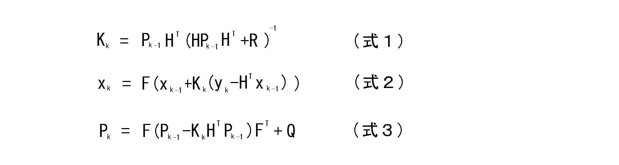
ここで、Kkはカルマン・ゲイン、Xkは推定平均値、Pkは推定分散値である。
ここで、Kkはカルマン・ゲイン、Xkは推定平均値、Pkは推定分散値である。
図4に示すように、カルマン・フィルタは、分散値算出部8と、カルマン・ゲイン算出部9と、平均値算出部10と、を備えている。
分散値算出部8は、共分散行列Pと、ノイズ行列Qと、分散値算出部8からの出力値である分散値と、カルマン・ゲイン算出部9からのカルマン・ゲインKが入力され、上記式3を用いて推定分散値Pkを算出するものである。
カルマン・ゲイン算出部9は、分散値算出部8から入力された推定分散値Pkと正規白色ノイズRとが入力され、上記式1を用いてカルマン・ゲインKを算出するものである。
分散値算出部8は、共分散行列Pと、ノイズ行列Qと、分散値算出部8からの出力値である分散値と、カルマン・ゲイン算出部9からのカルマン・ゲインKが入力され、上記式3を用いて推定分散値Pkを算出するものである。
カルマン・ゲイン算出部9は、分散値算出部8から入力された推定分散値Pkと正規白色ノイズRとが入力され、上記式1を用いてカルマン・ゲインKを算出するものである。
平均値算出部10は、減算器11と、乗算器12と、加算器13と、遅延器14と、乗算器15と、乗算器16と、を有し、減算器5から入力された観測値y(=SOCV-SOCi)とカルマン・ゲイン算出部9で得られたカルマン・ゲインKとに基づき、上記式2を用いて、状態変数xを演算するものである。
平均値算出部11の減算器11は、入力された観測値yから乗算器16の出力値を減算するものである。
乗算器12は、カルマン・ゲイン算出部9で得たカルマン・ゲインKに減算器11の出力値を掛けるものである。
加算器13は、乗算器12の出力値と乗算器15の出力値とを加算して得た加算値を遅延器14へ出力するものである。
遅延器14は、加算器13の加算値に1/zをかけて現在の1つ前の加算値を得てこの値を状態変数xとするものである。
乗算器15は、状態行列Fに遅延器14から入力された状態変数xを掛けて得た値を加算器13と乗算器16へ出力するものである。
乗算器16は、出力行列Hに乗算器15の出力値を掛けて得た値を減算器11へ出力するものである。
乗算器12は、カルマン・ゲイン算出部9で得たカルマン・ゲインKに減算器11の出力値を掛けるものである。
加算器13は、乗算器12の出力値と乗算器15の出力値とを加算して得た加算値を遅延器14へ出力するものである。
遅延器14は、加算器13の加算値に1/zをかけて現在の1つ前の加算値を得てこの値を状態変数xとするものである。
乗算器15は、状態行列Fに遅延器14から入力された状態変数xを掛けて得た値を加算器13と乗算器16へ出力するものである。
乗算器16は、出力行列Hに乗算器15の出力値を掛けて得た値を減算器11へ出力するものである。
なお、カルマン・フィルタでは、もともとバッテリBの状態量を推定するに際し、その推定の平均値と分散値を逐次的に推定算出しているので、これらの値を新たに別途算出する必要はない。
減算器7は、電流積算法充電率推定部3で推定した電流積算法充電率SOCiから、誤差推定部6で得た推定誤差niを減算して、バッテリBの充電率SOCを得るものである。減算器7は、本発明の充電率算出手段に相当する。
上記実施例1の充電率算出装置は、以下のように作用する。
バッテリBの充放電電流値Iと端子電圧値Vとは、充放電電流検出部1と端子電圧検出部2とにより充電率算出装置の起動中、逐次検出される。なお、これらの検出値は検出したアナログ値がデジタル値に変換されて、それらの後のデジタル演算に利用される。
バッテリBの充放電電流値Iと端子電圧値Vとは、充放電電流検出部1と端子電圧検出部2とにより充電率算出装置の起動中、逐次検出される。なお、これらの検出値は検出したアナログ値がデジタル値に変換されて、それらの後のデジタル演算に利用される。
電流積算法充電率推定部3では、充放電電流値と、充放電電流検出部1のあらかじめ与えておいた情報(分散と)、減算器7で得た充電率SOCと、に基づき、電流積算法充電率SOCiとこの分散Qiとを得る。
一方、開放電圧法充電率推定部4では、充放電電流値Iと、端子電圧値Vと、充放電電流検出部1および端子電圧検出部2のあらかじめ与えておいた情報(分散)と、に基づき、カルマン・フィルタを利用して、開放電圧法充電率SOCVとこの分散Qvとを得る。
一方、開放電圧法充電率推定部4では、充放電電流値Iと、端子電圧値Vと、充放電電流検出部1および端子電圧検出部2のあらかじめ与えておいた情報(分散)と、に基づき、カルマン・フィルタを利用して、開放電圧法充電率SOCVとこの分散Qvとを得る。
電流積算法充電率推定部3、開放電圧法充電率推定部4でそれぞれ得られた充電率の分散Qi、Qvと、減算器5で得られた観測値y(=SOCV-SOCi)とは、誤差推定部6に入力されて、ここでカルマン・フィルタを利用して電流積算法充電率SOCiの推定誤差niを推定する。
減算器7では、電流積算法充電率推定部3で得た電流積算法充電率SOCiからこのノイズとしての推定誤差niを減算して、バッテリBの充電率SOCを得る。
減算器7では、電流積算法充電率推定部3で得た電流積算法充電率SOCiからこのノイズとしての推定誤差niを減算して、バッテリBの充電率SOCを得る。
ここで、推定された充電率の時間的変化の結果につき、実施例1の充電率算出装置と従来発明(特許文献1に記載のもの)に記載のものとで比較した結果のイメージを図5に示す。
なお、同図において、(a)は電流積算法を用いて得られた充電率の時間的変化を示す図、(b)は開放電圧法を用いて得られた充電率の時間的変化を示す図、(c)は従来発明で得られた充電率の時間的変化を示す図、(d)は実施例1の充電率推定装置で得られた充電率の時間的変化を示す図である。
なお、同図において、(a)は電流積算法を用いて得られた充電率の時間的変化を示す図、(b)は開放電圧法を用いて得られた充電率の時間的変化を示す図、(c)は従来発明で得られた充電率の時間的変化を示す図、(d)は実施例1の充電率推定装置で得られた充電率の時間的変化を示す図である。
図5(a)に示すように、電流積算法による充電率の推定値は、時間が経過するにしたがって、誤差も積算されて行き、充電率真値から大きくずれて行くことが分かる。
また、図5(b)に示すように、開放電圧法による充電率の推定値と充電率真値との誤差は、時間が経つにつれ大きくなっていくということはないが、絶えず短い時間で充電率真値に対し、大きくなったり小さくなったりして、大きくずれていることが分かる。
また、図5(c)に示すように、従来発明のもので得られた充電率は、補正されているため、この充電率の誤差は、上記電流積算法や開放電圧法に比べると小さくなっている。しかしながら、この補正は電圧値を元に電流値を補正しているため、電圧値の影響から逃れることができない。この結果、電流検出部のばらつきを十分に補正しきれず、時間が経つにつれて誤差が大きくなっていくことが分かる。
一方、図5(d)に示すように、実施例1の充電率推定装置では、電圧の変動や充放電電流検出部1のばらつきをよく吸収して誤差を従来発明の場合より小さく抑え、かつ時間が経っても誤差が増大していかないことが分かる。
また、図5(b)に示すように、開放電圧法による充電率の推定値と充電率真値との誤差は、時間が経つにつれ大きくなっていくということはないが、絶えず短い時間で充電率真値に対し、大きくなったり小さくなったりして、大きくずれていることが分かる。
また、図5(c)に示すように、従来発明のもので得られた充電率は、補正されているため、この充電率の誤差は、上記電流積算法や開放電圧法に比べると小さくなっている。しかしながら、この補正は電圧値を元に電流値を補正しているため、電圧値の影響から逃れることができない。この結果、電流検出部のばらつきを十分に補正しきれず、時間が経つにつれて誤差が大きくなっていくことが分かる。
一方、図5(d)に示すように、実施例1の充電率推定装置では、電圧の変動や充放電電流検出部1のばらつきをよく吸収して誤差を従来発明の場合より小さく抑え、かつ時間が経っても誤差が増大していかないことが分かる。
次に、シミュレーションを行って得た、実施例1の充電率算出装置で推定した充電率SOCと充電率真値との比較結果を、図6に示す。
電流積算法充電率推定部3で推定した電流積算法充電率SOCiは、図6(a)に示すように、時間が経つにしたがって大きくずれて行くことが分かる。
また、開放電圧法充電率推定部4で推定した、開放電圧法充電率SOCVは、図6(b)に示すように、時間が経つにしたがって大きくずれて行くことはないものの、絶えず短時間で大きく変動し、たびたび大きな誤差が生じることが分かる。
しかしながら、実施例1の充電率推定装置では、図6(c)に示すように、電流積算法充電率推定部3と開放電圧法充電率推定部4で平均値、分散を考慮して誤差推定部6や減算器7で得た充電率SOCは、真値からのずれ、すなわち誤差は小さく、また時間が経つにしたがって大きくずれて行くこともないことが分かる。すなわち、実施例1の充電率推定装置は、高精度で充電率を推定できることが分かる。
電流積算法充電率推定部3で推定した電流積算法充電率SOCiは、図6(a)に示すように、時間が経つにしたがって大きくずれて行くことが分かる。
また、開放電圧法充電率推定部4で推定した、開放電圧法充電率SOCVは、図6(b)に示すように、時間が経つにしたがって大きくずれて行くことはないものの、絶えず短時間で大きく変動し、たびたび大きな誤差が生じることが分かる。
しかしながら、実施例1の充電率推定装置では、図6(c)に示すように、電流積算法充電率推定部3と開放電圧法充電率推定部4で平均値、分散を考慮して誤差推定部6や減算器7で得た充電率SOCは、真値からのずれ、すなわち誤差は小さく、また時間が経つにしたがって大きくずれて行くこともないことが分かる。すなわち、実施例1の充電率推定装置は、高精度で充電率を推定できることが分かる。
以上のように、実施例1のバッテリの充電率推定装置にあっては、以下の効果を得ることができる。
実施例1のバッテリの充電率推定装置にあっては、電流積算法充電率推定部3、開放電圧法充電率推定部4で電流積算法充電率SOCiと開放電圧法充電率SOCVを求めるとき、併せて平均値および分散をも用いて統計的な処理を施し、これらから推定誤差を求めて充電率を算出するようにしたので、充放電電流検出部1や端子電圧検出部2の特性の変動やばらつきがあっても、従来発明のものよりも高い精度でバッテリBの充電率SOCを推定できるようになる。
実施例1のバッテリの充電率推定装置にあっては、電流積算法充電率推定部3、開放電圧法充電率推定部4で電流積算法充電率SOCiと開放電圧法充電率SOCVを求めるとき、併せて平均値および分散をも用いて統計的な処理を施し、これらから推定誤差を求めて充電率を算出するようにしたので、充放電電流検出部1や端子電圧検出部2の特性の変動やばらつきがあっても、従来発明のものよりも高い精度でバッテリBの充電率SOCを推定できるようになる。
また、開放電圧法充電率推定部4および誤差推定部6には、それぞれカルマン・フィルタを用いたので、バッテリBの状態量を容易かつ高い精度で推測できるようになるとともに、カルマン・フィルタではもともと推定平均値と推定分散値を逐次的に推定算出していることから、これらの値を新たに別途算出する必要がなくなる。
また、電流積算法充電率推定部3では、減算器7で得た充電率を用いて電流積算法充電率SOCiを推定するので、高精度で電流積算法充電率SOCiを推定することが可能となる。
次に、本発明に係る実施例2のバッテリの充電率推定装置につき、図7に基づいて説明する。なお、実施例2にあっては、実施例1と同様の構成部分には実施例1のものと同じ番号を付し、それらの説明は省略する。
実施例2の充電率推定装置では、図1の実施例1において、電流積算法充電率推定部3の遅延器32に減算器7の出力値である充電率SOCを入力しているが、実施例2では減算器7の充電率SOCの代わりに、電流積算法充電率推定部3の出力値である電流積算法充電率SOCiを用いて、これを遅延器32へ入力するようにしている。
その他の構成は、実施例1と同じである。
実施例2の充電率推定装置では、図1の実施例1において、電流積算法充電率推定部3の遅延器32に減算器7の出力値である充電率SOCを入力しているが、実施例2では減算器7の充電率SOCの代わりに、電流積算法充電率推定部3の出力値である電流積算法充電率SOCiを用いて、これを遅延器32へ入力するようにしている。
その他の構成は、実施例1と同じである。
このように、電流積算法充電率推定部3の遅延器32に電流積算法充電率推定部3から出力された電流積算法充電率SOCiを入力しても、実施例1の場合より若干誤差が大きくなるものの、従来発明のものより充電率の誤差を小さくすることができる。
以上、本発明を上記各実施例に基づき説明してきたが、本発明はこれらの実施例に限られず、本発明の要旨を逸脱しない範囲で設計変更等があった場合でも、本発明に含まれる。
たとえば、本発明にあっては、実施例1、2ではノイズ行列Qを可変値としたが、通常のカルマン・フィルタのように固定値を用いることも可能である。この場合、可変値を用いた場合より若干推定精度は低下するものの、従来発明で得た推定精度より高い精度を得ることができることは言うまでもない。
1 充放電電流検出部(充放電電流検出手段)
2 端子電圧検出部(端子電圧検出手段)
3 電流積算法充電率推定部(電流積算法充電率推定手段)
3A 充電率算出部
3B 電流積算法分散算出部
4 開放電圧法推定部(開放線圧法法充電率推定手段)
4A 開放電圧推定部
4B 充電率算出部
4C 遅延器
4D 開放電圧部コンデンサ容量算出部
5 減算器
6 誤差推定部(誤差推定手段)
7 減算器(充電率算出手段)
8 分散値算出部
9 カルマン・ゲイン算出部
10 平均値算出部
B バッテリ
2 端子電圧検出部(端子電圧検出手段)
3 電流積算法充電率推定部(電流積算法充電率推定手段)
3A 充電率算出部
3B 電流積算法分散算出部
4 開放電圧法推定部(開放線圧法法充電率推定手段)
4A 開放電圧推定部
4B 充電率算出部
4C 遅延器
4D 開放電圧部コンデンサ容量算出部
5 減算器
6 誤差推定部(誤差推定手段)
7 減算器(充電率算出手段)
8 分散値算出部
9 カルマン・ゲイン算出部
10 平均値算出部
B バッテリ
Claims (3)
- バッテリの充放電電流値を検出する充放電電流検出手段と、
前記バッテリの端子電圧値を検出する端子電圧検出手段と、
前記充放電電流検出手段から入力された前記充放電電流を積算して得た充電率とこの前の時刻に得た充電率とから前記バッテリの電流積算法充電率を推定するとともに、前記充放電電流検出手段の検出精度に関する情報を元に電流積算法充電率の分散を算出する電流積算充電率推定手段と、
前記充放電電流検出手段から入力された前記充放電電流値と前記端子電圧検出手段から入力された前記端子電圧値とに基づきバッテリ等価回路モデルを用いて前記バッテリの開放電圧値を推定し、該開放電圧値から開放電圧法充電率を推定するとともに、前記充放電電流検出手段および前記端子電圧検出手段の検出精度に関する情報を元に開放電圧法充電率の分散を算出する開放電圧法充電率推定手段と、
前記開放電圧法充電率と前記電流積算法充電率との差、前記電流積算法充電率の分散、前記開放電圧法充電率の分散に基づいて前記電流積算法充電率の推定誤差を推定する誤差推定手段と、
前記電流積算法充電率と前記誤差推測手段で推定した推定誤差とから前記バッテリの充電率を求める充電率算出手段と、
ことを特徴とするバッテリの充電率推定装置。 - 請求項1に記載のバッテリの充電率推定装置において、
前記開放電圧法充電率推定手段および前記誤差推定手段は、それぞれカルマン・フィルタを用いる、
ことを特徴とするバッテリの充電率推定装置。 - 請求項1又は2に記載のバッテリの充電率推定装置において、
前記電流積算法充電率推定手段は、前記前に得た充電率に前記充電率算出手段で得た充電率を用いて前記電流積算法充電率を推定する、
ことを特徴とするバッテリの充電率推定装置。
Priority Applications (3)
| Application Number | Priority Date | Filing Date | Title |
|---|---|---|---|
| US13/978,240 US9329240B2 (en) | 2011-01-18 | 2011-12-01 | Battery SoC estimation device |
| EP11855964.0A EP2667211B1 (en) | 2011-01-18 | 2011-12-01 | Device for estimating state of charge of battery |
| CN201180065424.0A CN103328997B (zh) | 2011-01-18 | 2011-12-01 | 电池的充电率估计装置 |
Applications Claiming Priority (2)
| Application Number | Priority Date | Filing Date | Title |
|---|---|---|---|
| JP2011-007874 | 2011-01-18 | ||
| JP2011007874A JP5318128B2 (ja) | 2011-01-18 | 2011-01-18 | バッテリの充電率推定装置 |
Publications (1)
| Publication Number | Publication Date |
|---|---|
| WO2012098770A1 true WO2012098770A1 (ja) | 2012-07-26 |
Family
ID=46515407
Family Applications (1)
| Application Number | Title | Priority Date | Filing Date |
|---|---|---|---|
| PCT/JP2011/077748 Ceased WO2012098770A1 (ja) | 2011-01-18 | 2011-12-01 | バッテリの充電率推定装置 |
Country Status (5)
| Country | Link |
|---|---|
| US (1) | US9329240B2 (ja) |
| EP (1) | EP2667211B1 (ja) |
| JP (1) | JP5318128B2 (ja) |
| CN (1) | CN103328997B (ja) |
| WO (1) | WO2012098770A1 (ja) |
Cited By (6)
| Publication number | Priority date | Publication date | Assignee | Title |
|---|---|---|---|---|
| EP2816366A1 (en) * | 2013-06-18 | 2014-12-24 | VITO NV (Vlaamse Instelling voor Technologisch Onderzoek NV) | Monitoring charge stored in a battery |
| EP2837943A1 (en) * | 2013-08-12 | 2015-02-18 | O2Micro, Inc. | System and method for controlling a battery |
| CN104714188A (zh) * | 2015-03-31 | 2015-06-17 | 桂林电子科技大学 | 量测噪声方差阵相匹配的电池电荷状态估计方法与系统 |
| CN105283773A (zh) * | 2013-09-05 | 2016-01-27 | 日本康奈可株式会社 | 电池的健康度估计装置以及健康度估计方法 |
| WO2019138286A1 (ja) * | 2018-01-11 | 2019-07-18 | 株式会社半導体エネルギー研究所 | 二次電池の異常検知装置、異常検知方法、及びプログラム |
| JPWO2020100982A1 (ja) * | 2018-11-16 | 2021-10-14 | 株式会社Gsユアサ | 蓄電素子の管理装置、蓄電装置、車両、及び、蓄電素子の管理方法 |
Families Citing this family (59)
| Publication number | Priority date | Publication date | Assignee | Title |
|---|---|---|---|---|
| JP2012247339A (ja) * | 2011-05-30 | 2012-12-13 | Renesas Electronics Corp | 半導体集積回路およびその動作方法 |
| US8918300B2 (en) * | 2011-10-07 | 2014-12-23 | Calsonic Kansei Corporation | Apparatus and method for battery state of charge estimation |
| US20140340045A1 (en) * | 2012-01-26 | 2014-11-20 | Calsonic Kansei Corporation | Apparatus for battery state estimation |
| JP5944291B2 (ja) * | 2012-10-05 | 2016-07-05 | カルソニックカンセイ株式会社 | バッテリのパラメータ等推定装置およびその推定方法 |
| KR101547006B1 (ko) * | 2012-10-26 | 2015-08-24 | 주식회사 엘지화학 | 배터리 잔존 용량 추정 장치 및 방법 |
| JP6300000B2 (ja) | 2013-02-20 | 2018-03-28 | 株式会社Gsユアサ | 充電状態推定装置、充電状態推定方法 |
| JP6155774B2 (ja) | 2013-04-03 | 2017-07-05 | 株式会社Gsユアサ | 状態推定装置及び状態推定方法 |
| CN103278777B (zh) * | 2013-05-24 | 2015-08-19 | 杭州电子科技大学 | 一种基于动态贝叶斯网络的锂电池健康状况估计方法 |
| CN103675703B (zh) * | 2013-11-30 | 2016-02-24 | 西安交通大学 | 一种用于电池荷电状态估计方法 |
| CN107742915B (zh) * | 2013-12-06 | 2021-02-19 | 深圳市大疆创新科技有限公司 | 电池以及具有该电池的飞行器 |
| CN104714181B (zh) * | 2013-12-11 | 2017-10-27 | 广州汽车集团股份有限公司 | 一种获取电压与电池荷电状态关系的方法和系统 |
| CN103744027A (zh) * | 2013-12-20 | 2014-04-23 | 河北汉光重工有限责任公司 | 一种基于卡尔曼滤波的自校正电池soc估算方法 |
| CN103823187B (zh) * | 2014-01-22 | 2016-06-29 | 浙江工业大学 | 无线传感器网络节点的剩余电量的监测方法及其装置 |
| US9547045B2 (en) * | 2014-02-04 | 2017-01-17 | Gm Global Technology Operations, Llc | Methods and systems for determining a characteristic of a vehicle energy source |
| JP6128014B2 (ja) | 2014-02-27 | 2017-05-17 | トヨタ自動車株式会社 | 車両用充電制御装置 |
| US10345386B2 (en) * | 2014-03-03 | 2019-07-09 | Panasonic Intellectual Property Management Co., Ltd. | Battery state estimation device and method of estimating battery state |
| CN103901354B (zh) * | 2014-04-23 | 2016-08-17 | 武汉市欧力普能源与自动化技术有限公司 | 一种电动汽车车载动力电池soc预测方法 |
| CN103941195B (zh) * | 2014-05-05 | 2017-02-15 | 山东大学 | 基于小模型误差准则扩展卡尔曼滤波的电池soc估计方法 |
| CN104076293B (zh) * | 2014-07-07 | 2016-08-17 | 北京交通大学 | 基于观测器的锂电池soc估算误差的定量分析方法 |
| CN104242393A (zh) * | 2014-09-12 | 2014-12-24 | 安徽启光能源科技研究院有限公司 | 基于动态soc估算系统的电池管理系统 |
| FR3025889B1 (fr) * | 2014-09-12 | 2016-11-18 | Commissariat Energie Atomique | Gestion de la recharge de la batterie d'un vehicule electrique |
| TWI528043B (zh) * | 2014-10-14 | 2016-04-01 | 國立中山大學 | 電池之電量狀態及健康狀態的估測電路 |
| KR101783919B1 (ko) | 2014-10-31 | 2017-10-10 | 주식회사 엘지화학 | 개방전압 추정 장치 및 방법 |
| US10386418B2 (en) * | 2015-02-19 | 2019-08-20 | Mitsubishi Electric Corporation | Battery state estimation device |
| CN107408826B (zh) * | 2015-03-02 | 2020-07-10 | 日本汽车能源株式会社 | 电池控制装置以及车辆系统 |
| DE112015006416B4 (de) * | 2015-04-03 | 2019-03-21 | Mitsubishi Electric Corporation | Batterieladungszustandsschätzvorrichtung und Ladungszustandsschätzverfahren |
| JP6437100B2 (ja) * | 2015-04-15 | 2018-12-12 | 三菱電機株式会社 | 車両の電源装置 |
| CN105353313B (zh) * | 2015-09-28 | 2020-07-28 | 欣旺达电子股份有限公司 | 电池荷电状态的估算方法和装置 |
| CN105911480A (zh) * | 2015-11-11 | 2016-08-31 | 济南大学 | 一种动力电池soc估计方法 |
| CN106680720B (zh) * | 2015-11-11 | 2019-07-02 | 中国移动通信集团公司 | 基于车联网的车载蓄电池失效预警系统及方法 |
| CN105487016A (zh) * | 2016-01-21 | 2016-04-13 | 深圳市沃特玛电池有限公司 | 一种soc估值方法及其系统 |
| GB201617387D0 (en) * | 2016-10-13 | 2016-11-30 | Trw Automotive Gmbh | Control system for electric motor circuit |
| KR102634815B1 (ko) * | 2016-11-22 | 2024-02-07 | 삼성전자주식회사 | 오차 보정에 기초한 배터리 상태 추정 방법 및 장치 |
| JP6776904B2 (ja) * | 2017-01-13 | 2020-10-28 | 株式会社デンソー | 電池パック及び電源システム |
| US10670662B2 (en) | 2017-03-02 | 2020-06-02 | Mediatek Inc. | Method and apparatus for calibrating coulomb counting based state-of-charge estimation |
| US11320491B2 (en) * | 2017-03-06 | 2022-05-03 | Volvo Truck Corporation | Battery cell state of charge estimation method and a battery state monitoring system |
| CN106959420B (zh) * | 2017-03-10 | 2019-04-09 | 南京航空航天大学 | 一种动力电池组soc和soh的自适应估计方法 |
| JP6822300B2 (ja) * | 2017-04-27 | 2021-01-27 | トヨタ自動車株式会社 | 充電率推定方法および車載の電池システム |
| WO2019003377A1 (ja) | 2017-06-29 | 2019-01-03 | 株式会社東芝 | 蓄電池残量推定装置、蓄電池残量推定方法、およびプログラム |
| CN109425829A (zh) * | 2017-08-31 | 2019-03-05 | 加百裕工业股份有限公司 | 锂电池电容量检测方法 |
| WO2019053557A1 (ja) | 2017-09-14 | 2019-03-21 | 株式会社半導体エネルギー研究所 | 二次電池の異常検知システム及び二次電池の異常検出方法 |
| US11035902B2 (en) * | 2017-10-10 | 2021-06-15 | Integrated Device Technology, Inc. | Advanced fuel gauge |
| KR102239365B1 (ko) | 2017-10-20 | 2021-04-09 | 주식회사 엘지화학 | 배터리 충전 상태 추정 장치 |
| KR102244140B1 (ko) | 2017-12-21 | 2021-04-22 | 주식회사 엘지화학 | 배터리의 충전 상태를 캘리브레이션하기 위한 방법 및 배터리 관리 시스템 |
| JP7183577B2 (ja) * | 2018-06-01 | 2022-12-06 | マツダ株式会社 | バッテリ容量推定装置、およびバッテリ容量推定方法 |
| US11899069B2 (en) | 2018-12-21 | 2024-02-13 | Cummins Inc. | SOC and SOH co-estimation systems and methods for electric vehicles |
| KR102722271B1 (ko) | 2019-02-07 | 2024-10-24 | 주식회사 엘지에너지솔루션 | 배터리 관리 장치, 배터리 관리 방법 및 배터리팩 |
| JP6719853B1 (ja) * | 2019-03-25 | 2020-07-08 | マレリ株式会社 | 充電制御装置、充電制御方法および充電制御プログラム |
| KR102821614B1 (ko) * | 2019-10-29 | 2025-06-16 | 주식회사 엘지에너지솔루션 | Soc 추정 방법 및 이를 이용한 배터리 시스템 |
| US11360147B2 (en) | 2020-03-03 | 2022-06-14 | Karma Automotive Llc | Method of determining the state of charge of a battery used in an electric vehicle |
| CN112034366B (zh) * | 2020-08-25 | 2023-07-14 | 惠州市蓝微电子有限公司 | 一种soc动态补偿方法及电子系统 |
| JP2022071900A (ja) * | 2020-10-29 | 2022-05-17 | シェアード・モビリティ・ネットワークス株式会社 | 推定システム、及び推定プログラム |
| DE102020129131A1 (de) * | 2020-11-05 | 2022-05-05 | Dr. Ing. H.C. F. Porsche Aktiengesellschaft | Verfahren und System zu einer Ladezustandsbeobachtung einer Wechselstrombatterie |
| FR3121643A1 (fr) * | 2021-04-08 | 2022-10-14 | Psa Automobiles Sa | Systeme d’estimation de tension en circuit ouvert de batterie de traction de vehicule automobile, procede et vehicule comprenant un tel systeme |
| CN113777517B (zh) * | 2021-09-13 | 2023-10-17 | 傲普(上海)新能源有限公司 | 储能电站短板电芯筛选方法 |
| KR102693089B1 (ko) * | 2021-10-12 | 2024-08-09 | 경북대학교 산학협력단 | 배터리 상태 추정 장치 및 배터리 상태 추정 방법 |
| US12613282B2 (en) * | 2022-11-08 | 2026-04-28 | Cirrus Logic Inc. | Systems and methods for determining battery state of charge |
| US20240186808A1 (en) * | 2022-12-05 | 2024-06-06 | Enphase Energy, Inc. | Storage system configured for use with an energy management system |
| CN119051226B (zh) * | 2024-11-01 | 2025-05-06 | 深圳市永新能科技有限公司 | 一种用于锂电池的剩余电量在线监测方法、设备及系统 |
Citations (4)
| Publication number | Priority date | Publication date | Assignee | Title |
|---|---|---|---|---|
| JP2006020401A (ja) * | 2004-06-30 | 2006-01-19 | Fuji Heavy Ind Ltd | ハイブリッド車のバッテリ管理システム |
| JP2009250970A (ja) | 2008-04-03 | 2009-10-29 | Hyundai Motor Co Ltd | バッテリーの残存容量の推定方法 |
| JP2010203854A (ja) | 2009-03-02 | 2010-09-16 | Nissan Motor Co Ltd | 二次電池の内部状態推定装置 |
| JP2010271286A (ja) * | 2009-05-25 | 2010-12-02 | Mitsubishi Heavy Ind Ltd | 電池劣化判定装置、電池劣化判定方法、及びプログラム |
Family Cites Families (23)
| Publication number | Priority date | Publication date | Assignee | Title |
|---|---|---|---|---|
| US5617007A (en) * | 1994-08-17 | 1997-04-01 | International Business Machines Corporation | Battery charging method and apparatus using current control |
| JP3716619B2 (ja) * | 1998-05-14 | 2005-11-16 | 日産自動車株式会社 | 電池の残容量計 |
| JP3869676B2 (ja) * | 2000-12-08 | 2007-01-17 | 矢崎総業株式会社 | 車両用バッテリの開回路電圧推定方法及び装置 |
| US6359419B1 (en) * | 2000-12-27 | 2002-03-19 | General Motors Corporation | Quasi-adaptive method for determining a battery's state of charge |
| KR100387491B1 (ko) * | 2000-12-28 | 2003-06-18 | 현대자동차주식회사 | 전기 자동차의 배터리 고장 진단방법 |
| US6845332B2 (en) * | 2001-11-16 | 2005-01-18 | Toyota Jidosha Kabushiki Kaisha | State of charge calculation device and state of charge calculation method |
| JP3714321B2 (ja) | 2002-11-25 | 2005-11-09 | 日産自動車株式会社 | 二次電池の充電率推定装置 |
| JP3714333B2 (ja) * | 2003-02-28 | 2005-11-09 | 日産自動車株式会社 | 二次電池の入出力可能電力推定装置 |
| JP4015128B2 (ja) | 2003-07-09 | 2007-11-28 | 古河電気工業株式会社 | 充電率推定方法、充電率推定装置、電池システム及び車両用電池システム |
| CN100573178C (zh) * | 2003-07-09 | 2009-12-23 | 古河电气工业株式会社 | 充电率推测方法、充电率推测装置和电池系统 |
| JP4649101B2 (ja) * | 2003-09-10 | 2011-03-09 | 株式会社日本自動車部品総合研究所 | 二次電池の状態検知装置および状態検知方法 |
| JP4830382B2 (ja) * | 2005-07-19 | 2011-12-07 | 日産自動車株式会社 | 二次電池の充電率推定装置 |
| KR100669477B1 (ko) * | 2005-12-22 | 2007-01-16 | 삼성에스디아이 주식회사 | 배터리의 soc 보정 방법 및 이를 이용한 배터리 관리시스템 |
| US7652448B2 (en) * | 2007-04-12 | 2010-01-26 | International Truck Intellectual Property Company, Llc | Vehicle battery state of charge indicator |
| US7830119B2 (en) * | 2007-08-29 | 2010-11-09 | Gm Global Technology Operations, Inc. | Adaptive battery estimator and method |
| JP4959511B2 (ja) * | 2007-11-07 | 2012-06-27 | 富士重工業株式会社 | 蓄電池用充電制御装置 |
| JP4893653B2 (ja) * | 2008-02-19 | 2012-03-07 | トヨタ自動車株式会社 | 車両、二次電池の充電状態推定方法および車両の制御方法 |
| JP4983818B2 (ja) * | 2009-02-12 | 2012-07-25 | ソニー株式会社 | 電池パックおよび電池容量計算方法 |
| US8004243B2 (en) * | 2009-04-08 | 2011-08-23 | Tesla Motors, Inc. | Battery capacity estimating method and apparatus |
| JP4772137B2 (ja) | 2009-06-02 | 2011-09-14 | トヨタ自動車株式会社 | バッテリ使用機器の制御装置 |
| US8207706B2 (en) * | 2009-08-04 | 2012-06-26 | Honda Motor Co., Ltd. | Method of estimating battery state of charge |
| JP5400732B2 (ja) * | 2010-09-09 | 2014-01-29 | カルソニックカンセイ株式会社 | パラメータ推定装置 |
| TW201224485A (en) * | 2010-12-02 | 2012-06-16 | Ind Tech Res Inst | State-of-charge estimation method and battery control unit |
-
2011
- 2011-01-18 JP JP2011007874A patent/JP5318128B2/ja not_active Expired - Fee Related
- 2011-12-01 CN CN201180065424.0A patent/CN103328997B/zh not_active Expired - Fee Related
- 2011-12-01 US US13/978,240 patent/US9329240B2/en not_active Expired - Fee Related
- 2011-12-01 EP EP11855964.0A patent/EP2667211B1/en not_active Not-in-force
- 2011-12-01 WO PCT/JP2011/077748 patent/WO2012098770A1/ja not_active Ceased
Patent Citations (4)
| Publication number | Priority date | Publication date | Assignee | Title |
|---|---|---|---|---|
| JP2006020401A (ja) * | 2004-06-30 | 2006-01-19 | Fuji Heavy Ind Ltd | ハイブリッド車のバッテリ管理システム |
| JP2009250970A (ja) | 2008-04-03 | 2009-10-29 | Hyundai Motor Co Ltd | バッテリーの残存容量の推定方法 |
| JP2010203854A (ja) | 2009-03-02 | 2010-09-16 | Nissan Motor Co Ltd | 二次電池の内部状態推定装置 |
| JP2010271286A (ja) * | 2009-05-25 | 2010-12-02 | Mitsubishi Heavy Ind Ltd | 電池劣化判定装置、電池劣化判定方法、及びプログラム |
Non-Patent Citations (1)
| Title |
|---|
| See also references of EP2667211A4 |
Cited By (17)
| Publication number | Priority date | Publication date | Assignee | Title |
|---|---|---|---|---|
| EP2816366A1 (en) * | 2013-06-18 | 2014-12-24 | VITO NV (Vlaamse Instelling voor Technologisch Onderzoek NV) | Monitoring charge stored in a battery |
| WO2014202684A3 (en) * | 2013-06-18 | 2015-02-19 | Vlaamse Instelling Voor Technologisch Onderzoek Nv (Vito Nv) | Monitoring charge stored in a battery |
| US10295600B2 (en) | 2013-06-18 | 2019-05-21 | Vlaamse Instelling Voor Technologisch Onderzoek Nv (Vito Nv) | Monitoring charge stored in a battery |
| EP2837943A1 (en) * | 2013-08-12 | 2015-02-18 | O2Micro, Inc. | System and method for controlling a battery |
| CN105283773A (zh) * | 2013-09-05 | 2016-01-27 | 日本康奈可株式会社 | 电池的健康度估计装置以及健康度估计方法 |
| CN104714188A (zh) * | 2015-03-31 | 2015-06-17 | 桂林电子科技大学 | 量测噪声方差阵相匹配的电池电荷状态估计方法与系统 |
| CN104714188B (zh) * | 2015-03-31 | 2017-05-24 | 桂林电子科技大学 | 量测噪声方差阵相匹配的电池电荷状态估计方法与系统 |
| JPWO2019138286A1 (ja) * | 2018-01-11 | 2021-02-12 | 株式会社半導体エネルギー研究所 | 二次電池の異常検知装置、異常検知方法、及びプログラム |
| WO2019138286A1 (ja) * | 2018-01-11 | 2019-07-18 | 株式会社半導体エネルギー研究所 | 二次電池の異常検知装置、異常検知方法、及びプログラム |
| JP7234140B2 (ja) | 2018-01-11 | 2023-03-07 | 株式会社半導体エネルギー研究所 | 二次電池の異常検知装置、異常検知方法、プログラム、二次電池の状態推定方法、及び二次電池の充電状態推定装置 |
| TWI814765B (zh) * | 2018-01-11 | 2023-09-11 | 日商半導體能源研究所股份有限公司 | 二次電池的異常檢測裝置、異常檢測方法、充電狀態推測方法、充電狀態推測裝置以及電腦可讀取媒體 |
| JP2024100785A (ja) * | 2018-01-11 | 2024-07-26 | 株式会社半導体エネルギー研究所 | 二次電池の異常検知装置及び二次電池 |
| TWI856802B (zh) * | 2018-01-11 | 2024-09-21 | 日商半導體能源研究所股份有限公司 | 二次電池的異常檢測裝置及二次電池 |
| JP7648831B2 (ja) | 2018-01-11 | 2025-03-18 | 株式会社半導体エネルギー研究所 | 二次電池の異常検知装置及び二次電池 |
| US12442862B2 (en) | 2018-01-11 | 2025-10-14 | Semiconductor Energy Laboratory Co., Ltd. | Device detecting abnormality of secondary battery, abnormality detection method, and program |
| JPWO2020100982A1 (ja) * | 2018-11-16 | 2021-10-14 | 株式会社Gsユアサ | 蓄電素子の管理装置、蓄電装置、車両、及び、蓄電素子の管理方法 |
| JP7428135B2 (ja) | 2018-11-16 | 2024-02-06 | 株式会社Gsユアサ | 蓄電素子の管理装置、蓄電装置、車両、及び、蓄電素子の管理方法 |
Also Published As
| Publication number | Publication date |
|---|---|
| US9329240B2 (en) | 2016-05-03 |
| CN103328997A (zh) | 2013-09-25 |
| EP2667211A4 (en) | 2015-12-09 |
| JP2012149947A (ja) | 2012-08-09 |
| CN103328997B (zh) | 2015-09-09 |
| EP2667211B1 (en) | 2016-10-12 |
| EP2667211A1 (en) | 2013-11-27 |
| JP5318128B2 (ja) | 2013-10-16 |
| US20130297243A1 (en) | 2013-11-07 |
Similar Documents
| Publication | Publication Date | Title |
|---|---|---|
| JP5318128B2 (ja) | バッテリの充電率推定装置 | |
| JP5393837B2 (ja) | バッテリの充電率推定装置 | |
| JP5404964B2 (ja) | バッテリの充電率推定装置及び充電率推定方法 | |
| JP6403746B2 (ja) | 電池状態推定装置 | |
| JP5393619B2 (ja) | バッテリの充電率推定装置 | |
| JP6182025B2 (ja) | バッテリの健全度推定装置および健全度推定方法 | |
| JP5389136B2 (ja) | 充電率推定装置およびその方法 | |
| JP5863603B2 (ja) | 電池状態推定装置、電池制御装置、電池システム、電池状態推定方法 | |
| CN108369258A (zh) | 状态估计装置、状态估计方法 | |
| JPWO2016059869A1 (ja) | 二次電池の充電状態推定装置及びその充電状態推定方法 | |
| JP5329500B2 (ja) | バッテリの充電率推定装置 | |
| JP3669202B2 (ja) | バッテリ状態監視装置 | |
| JP5389137B2 (ja) | 充電率推定装置およびその方法 | |
| JP2017161351A (ja) | 二次電池の充電率推定方法、充電率推定装置及び充電率推定プログラム | |
| JP5432931B2 (ja) | バッテリの充電率推定装置 |
Legal Events
| Date | Code | Title | Description |
|---|---|---|---|
| 121 | Ep: the epo has been informed by wipo that ep was designated in this application |
Ref document number: 11855964 Country of ref document: EP Kind code of ref document: A1 |
|
| WWE | Wipo information: entry into national phase |
Ref document number: 13978240 Country of ref document: US |
|
| REEP | Request for entry into the european phase |
Ref document number: 2011855964 Country of ref document: EP |
|
| WWE | Wipo information: entry into national phase |
Ref document number: 2011855964 Country of ref document: EP |
|
| NENP | Non-entry into the national phase |
Ref country code: DE |