WO2012101877A1 - Humidificateur - Google Patents
Humidificateur Download PDFInfo
- Publication number
- WO2012101877A1 WO2012101877A1 PCT/JP2011/074053 JP2011074053W WO2012101877A1 WO 2012101877 A1 WO2012101877 A1 WO 2012101877A1 JP 2011074053 W JP2011074053 W JP 2011074053W WO 2012101877 A1 WO2012101877 A1 WO 2012101877A1
- Authority
- WO
- WIPO (PCT)
- Prior art keywords
- water
- heat transfer
- plate
- transfer body
- humidifier
- Prior art date
- Legal status (The legal status is an assumption and is not a legal conclusion. Google has not performed a legal analysis and makes no representation as to the accuracy of the status listed.)
- Ceased
Links
Images


Classifications
-
- F—MECHANICAL ENGINEERING; LIGHTING; HEATING; WEAPONS; BLASTING
- F24—HEATING; RANGES; VENTILATING
- F24F—AIR-CONDITIONING; AIR-HUMIDIFICATION; VENTILATION; USE OF AIR CURRENTS FOR SCREENING
- F24F6/00—Air-humidification, e.g. cooling by humidification
- F24F6/02—Air-humidification, e.g. cooling by humidification by evaporation of water in the air
- F24F6/08—Air-humidification, e.g. cooling by humidification by evaporation of water in the air using heated wet elements
- F24F6/10—Air-humidification, e.g. cooling by humidification by evaporation of water in the air using heated wet elements heated electrically
Definitions
- the present invention relates to a humidifier that humidifies a room or the like.
- humidifiers are known that heat and evaporate water by a heating means to humidify a room or the like.
- various humidifiers there is one that employs a method in which tap water stored in a water tank is absorbed by a water absorbing plate (water absorbing material) and heated to evaporate the water and humidify it.
- Reference 1 Japanese Patent No. 3769676 discloses a humidifier employing the above-described method, and a needle punched nonwoven fabric in which rayon fibers and polyester fibers are mixed is used as a water absorbing material. .
- This invention is made
- a first form of a humidifier according to the present invention includes a water tank, a heat transfer plate, a water absorption plate, a heating means, and a control unit.
- the water tank is configured to store water.
- the heat transfer plate is formed in a plate shape from a material having thermal conductivity, and is attached to the water tank.
- the water absorbing plate is disposed on one surface of the heat transfer plate and is configured to absorb and hold water stored in the water tank.
- the heating means is disposed on the other surface of the heat transfer plate.
- the control unit is configured to control the heating unit to heat water held on the water absorption plate via the heat transfer plate to generate water vapor.
- the water absorbing plate has an impurity trapping layer and a water absorbing layer.
- the impurity trapping layer is configured to absorb water stored in the water tank and remove impurities from the absorbed water.
- the water absorption layer is configured to absorb and retain water from which impurities have been removed by the impurity trapping layer.
- the impurity trapping layer is disposed on one surface of the water absorption layer in the first embodiment.
- the other surface of the water absorption layer is in contact with the one surface of the heat transfer plate.
- a third form of the humidifier according to the present invention is a board in which the water absorption layer is formed using a composite polyester fiber in the first or second form.
- a fourth aspect of the humidifier according to the present invention is a board in which the impurity supplemental layer is formed using rayon fibers in any one of the first to third.
- the impurity trapping layer is formed using a needle punch manufacturing method.
- a humidifier according to a sixth aspect of the present invention is the humidifier according to any one of the first to fifth aspects, wherein the heat transfer plate includes a normal vector of a surface of water in the water tank and the heat transfer plate. Are attached to the water tank so that the angle between the normal vector and the normal vector is an acute angle.
- a seventh aspect of the humidifier according to the present invention includes a fastener for fixing the heating means to the heat transfer body in any one of the first to sixth aspects.
- a protrusion is formed on the other surface of the heat transfer body.
- the heating means is formed in a plate shape, has a through hole through which the protrusion is passed, and is disposed on the other surface of the heat transfer plate so that the protrusion passes through the through hole.
- the said fastener is attached to the front-end
- a recess for accommodating the water absorbing plate is formed on one surface of the heat transfer body.
- FIGS. 1-9 a humidifier 1 according to an embodiment of the present invention will be described with reference to FIGS. 1-9.
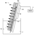
- the humidifier 1 includes a water absorbing material 50 that absorbs water stored in a water tank (hereinafter referred to as the water storage tank 7), a heat transfer body 52 in which the water absorbing material 50 is disposed on the front side, Heating means 53 disposed on the back side of the heat transfer body 52 is provided.
- a water absorbing material 50 that absorbs water stored in a water tank (hereinafter referred to as the water storage tank 7)
- a heat transfer body 52 in which the water absorbing material 50 is disposed on the front side, Heating means 53 disposed on the back side of the heat transfer body 52 is provided.
- the water-absorbing material 50 includes a water-absorbing layer 50a made of a water-absorbing material provided in contact with the heat transfer body 52, and an impurity trapping layer 50b that is stacked on the water-absorbing layer 50a and traps impurities contained in the water.
- a water-absorbing layer 50a made of a water-absorbing material provided in contact with the heat transfer body 52
- an impurity trapping layer 50b that is stacked on the water-absorbing layer 50a and traps impurities contained in the water.
- the water absorbing material 50 and the heat transfer body 52 are formed in a plate-like body and are disposed in a state where the water absorbing material 50 is laminated on the front surface side of the heat transfer body 52, and the water absorbing material 50 is obliquely upward.
- the heat transfer body 52 is provided so as to be disposed.
- FIGS. 1-9 the location used as the principal part of the humidifier 1 is illustrated, and illustration of case 8 grade
- the humidifier 1 includes a lid 2, a water supply tank 3, a steam cover 4, a steam generator 5, a water level detection means 6, a water tank 7, and a case 8. ing.
- the water supply tank 3 and the steam cover 4 are configured so as to be integrally assembled above the water tank 7, and these are stored in the case 8 in an integrated state.
- the lid 2 is a flat plate formed so as to close the upper surface of the case 8, and the lid 2 is formed with a plurality of outlets 20, and steam (water vapor) generated from the steam generator 5. However, it blows out from the blower outlet 20 through the opening part 40 formed in the steam cover 4.
- the humidifier 1 includes an operation display unit (not shown), and includes an operation switch that can turn on and off the heating unit 53, a display unit that displays an on / off state of the operation switch, and the like. is doing.
- the operation switch is turned on, the heating means 53 is driven to start the humidifying operation, and when the operation switch is turned off, the driving of the heating means 53 is stopped and the humidifying operation is stopped.
- the case 8 includes a front plate 80 provided on the front surface, the water supply tank 3 integrated as described above, and a box-shaped accommodation portion 81 in which the steam cover 4 and the water storage tank 7 are accommodated.
- the shape of the case 8 is not limited to the illustrated example, but the illustrated example is formed in a concave shape on the front side of the panel (humidity adjusting panel) 10 having the humidity control function shown in FIGS. It is formed thin so that it can be stored in the receiving recess 11.
- a front plate 80 that is gently curved is provided on the front surface of the case 8, and in the vicinity of the left and right end portions of the front plate 80, a handle portion 80 a that is formed in a concave shape is formed.
- a rear surface of the front plate 80 is provided with an accommodating portion 81 having an open top surface and a substantially rectangular parallelepiped shape.
- the water supply tank 3 includes a water supply tank main body 33 made of an oval shaped housing in plan view, a water injection port 30 that serves as a water spout, and a cap 31 that seals the water injection port 30.
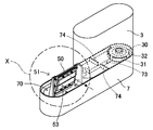
- the water storage tank 7 is composed of an oval frame in plan view, and includes a water reservoir 70 into which the water-absorbing material 50 is immersed, a connecting portion 71 to which the water supply tank 3 is connected, and water from the water supply tank 3 to the water reservoir 70. And a pedestal portion 74 in which the water supply tank 3 is installed.
- the water storage tank 7 is provided with a water reservoir 70 on one side, a connecting part 71 on the other side, and a flow path 73 so as to connect between the water reservoir 70 and the connecting part 71.
- a water absorbing material 50 is immersed in the water reservoir 70, and the water absorbing material 50 is disposed obliquely upward. Therefore, the water reservoir 70 is disposed at the rear position of the front plate 80 so that the steam is efficiently blown forward from the outlet 20.
- an attachment base portion 73 to which a holder 51 for locking the water absorbing material 50 is attached and fixed is provided behind the water reservoir portion 70.
- the water supply tank 3 is configured to be detachably attached to a connecting portion 71 provided in the water tank 7.
- the water supply tank 3 is configured to be portable so that it can be removed from the connecting portion 71 of the water storage tank 7 and carried to a place where there is a faucet.
- An open water injection port 30 is formed on the lower surface side of the water supply tank 3, and when supplying tap water, the cap 31 is removed by turning the water supply tank 3 upside down, and water is supplied from the water injection port 30.
- the water injection port 30 is sealed with a cap 31, and the cap 31 is provided with a valve portion 32 having a valve function.
- the connecting portion 71 is provided with a protruding valve contact portion 72, and the valve portion 32 is configured such that when the valve contact portion 72 contacts the valve seat 72, a valve seat (not shown) is opened. Has been.
- valve portion 32 when the water supply tank 3 is carried, the valve portion 32 is in a closed state. When the valve portion 32 is in contact with and connected to the valve contact portion 72, the valve portion 32 is opened.
- the shapes of the water supply tank 3 and the water tank 7 are not limited to the illustrated examples.
- the water tank 7 is provided with a water level detection means 6 for detecting the water level of the water tank 7.
- the configuration of the water level detection means 6 is not particularly limited, and may be configured to detect the water level of the water supply tank 3 or may detect the water level of the water reservoir 70. In short, any material that can detect that the water-absorbing material 50 has insufficient water to absorb water may be used.
- the water level detecting means 6 is provided on the lower surface side of the water supply tank 3 connected to the water storage tank 7 and in the vicinity of the water reservoir 70 and the flow path 73.
- a steam generating unit 5 is provided above the water reservoir 70 of the water storage tank 7, and a steam cover 4 is provided so as to cover the steam generating unit 5.
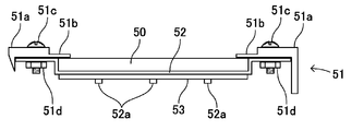
- the steam generating unit 5 includes a water absorbing material 50, a holder 51 that locks the water absorbing material 50, a heat transfer body 52, and a heating means 53.
- the water absorbing material 50 is formed in a vertically long, substantially rectangular plate shape so that it can be disposed in a state where it is immersed in water stored in the water reservoir 70 and laminated on the front side of the heat transfer body 52 (see FIG. 3). ), The size of the water absorbing material 50 is formed so as to be accommodated in a recess 52c of the heat transfer body 52, which will be described later, and to be provided with a portion where the lower portion of the water reservoir 70 is immersed.
- the water-absorbing material 50 has a two-layer structure, and is laminated on the water-absorbing layer 50a and a water-absorbing layer 50a made of a water-absorbing material provided in contact with the heat transfer body 52 as described above. And an impurity trapping layer 50b for trapping impurities contained in water.
- the water absorption layer 50a disposed in close contact with the heat transfer body 52 is a lower layer, and the impurity trapping layer 50b is laminated on the upper layer of the water absorption layer 50a.
- the material for forming the water absorption layer 50a is not particularly limited as long as it is made of a water-absorbing material with good water absorption efficiency, can absorb the water in the water reservoir 70 and can withstand the heat transmitted from the heat transfer body 52. is not. That is, the water absorption layer 50a may be any material that sucks up water stored in the water reservoir 70 by capillary action.
- a fabric made of polyester fiber, polypropylene fiber, rayon fiber, cotton or the like, a knitted fabric, or a nonwoven fabric is used as the water absorption layer 50a.
- a composite polyester fiber board is desirably used as the absorbent layer 50a.
- the composite polyester fiber board is formed using, for example, a hard porous body made of polyester fiber.
- “Unibex SB (registered trademark)” manufactured by Unitika Ltd. is used for the hard porous body made of polyester fiber.
- the water absorption speed can be improved by the water absorption layer 50a.
- the composite polyester fiber board has shape retention and can be made a relatively hard fiber board. Even when a material that generates water is used, the water supply layer 50a regulates the elongation of the water absorbing material 50, so that the elongation of the water absorbing material 50 can be suppressed.
- the water absorbing material 50 is disposed in a state of being laminated on the front side of the heat transfer body 52, and the heat transfer body 52 is inclined so that the water absorbing material 50 is disposed obliquely upward. It is desirable to be provided. According to this, since the water absorbing material 50 can be disposed in close contact with the front surface of the heat transfer body 52 by utilizing its own weight as described later, the water absorbing material 50 with less elongation is arranged. Synergistic effects of the installation can further enhance the adhesion between the water-absorbing material 50 and the heat transfer body 52, and can withstand long-term use without reducing the humidification ability.
- the material for forming the impurity trapping layer 50b is not particularly limited as long as impurities contained in water can be attached and trapped.
- a rayon fiber board produced by a needle punch manufacturing method is preferably used. It is done.
- the impurity trapping layer 50b is produced by stacking a plurality of rayon fiber sheets in the thickness direction and bonding them together by needle punching.
- the impurity trapping layer 50b may be a cotton fiber sheet.
- the impurities trapping in the water can be reliably trapped by the impurity trapping layer 50b.
- the lamination method of the water absorption layer 50a and the impurity trapping layer 50b is not particularly limited as long as it is superposed so that water absorption and impurity adhesion can be maintained.
- the four circumferences may be laminated or integrated by bonding or sewing.
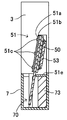
- the holder 51 is provided in a substantially upright state with respect to the mounting base portion 73.
- the holder 51 is formed so as to hold both sides of the heat transfer body 52 and holds the heat transfer body 52 in an inclined state, and the water absorbing material 50 is in close contact with the front surface of the heat transfer body 52.
- a locking portion 51b to be locked and a fixing portion 51e fixed to the mounting base portion 73 are provided.
- the holding part 51a is provided in an obliquely standing state, and a plurality of through holes are formed in the vertical direction in order to fix and hold the left and right side parts 52d and 52d of the heat transfer body 52.
- the illustrated example shows a state in which the fixing tool 51c is inserted into the through hole, and the heat transfer body 52 is fixed and held by the fixing tool 51c.
- the inclination angle ⁇ of the holding portion 51a is not particularly limited.
- the holding portion 51a is inclined so as to have an acute angle (preferably 65 ° to 85 °) with respect to the horizontal plane (the mounting base portion 73 and the fixing portion 51e). It is desirable that When the water storage tank 7 is disposed on a plane parallel to the horizontal plane, the upper surface of the attachment base 73 and the upper surface of the fixing portion 51e are parallel to the horizontal plane.
- the inclination angle ⁇ is equal to the angle between the normal vector of one surface (front surface) of the heat transfer plate 52 and the normal vector of the horizontal plane when the water tank (water storage tank) 7 is arranged on a plane parallel to the horizontal plane. . Therefore, in the heat transfer plate 52, when the water tank 7 is arranged on a plane parallel to the horizontal plane, the angle between the normal vector of the horizontal plane and the normal vector of one surface (front surface) of the heat transfer plate 52 is an acute angle.
- the water tank 7 is attached.
- the heat transfer plate 52 is placed in the water tank 7 so that the angle between the normal vector of the surface of water in the water tank 7 and the normal vector of one surface (front surface) of the heat transfer plate 52 is an acute angle. It is attached.
- the water absorbing material 50 is not in close contact with the heat transfer body 52 using a separate member, but is in close contact with the heat transfer body 52 using its own weight.
- the adhesion of the heat transfer body 52 does not deteriorate. Therefore, efficient humidification can be performed over a long period of time, and a decrease in the humidifying ability of the humidifier 1 can be prevented.
- the planar installation space of the holder 51 is widened, so that it is difficult to make the humidifier 1 thin.
- the inclination angle of the holding portion 51a is 85 degrees ⁇ 90 degrees, the humidifier 1 can be thinned, but the water absorbing material 50 is placed on the front surface of the heat transfer body 52 by utilizing the weight of the water absorbing material 50. It becomes difficult to dispose the water absorbent material in close contact, and the water absorbing material 50 may slip off.
- the water absorbing material 50 cannot be disposed obliquely upward, and the water absorbing material 50 is brought into close contact with the front surface of the heat transfer body 52 by utilizing the weight of the water absorbing material 50. It becomes impossible to arrange by.
- the locking portion 51b is formed so as to further extend in the opposing direction from the opposing ends of the holding portions 51a provided on both sides of the heat transfer body 52.
- the water absorbing material 50 can be disposed so as to press the upper sides of the left and right ends of the water absorbing material 50 in the direction of the heat transfer body 52 without falling forward.
- the fixing portion 51e is formed with a plurality of through holes so that the fixing portion 51e is mounted on the mounting base portion 73. In the illustrated example, the fixing portion 51e is fixed to the mounting base portion 73. The state fixed by the tool 51f is shown.
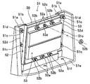
- the heat transfer body 52 is provided in order to efficiently transmit the heat generated by the heating means 53 to the water absorbing material 50, and is made of aluminum, aluminum alloy, or the like having good thermal conductivity, and is formed in a substantially rectangular plate shape.
- a recess 52c for holding the water absorbing material 50 is formed on the front side of the heat transfer body 52. Since the left and right side portions 52d of the heat transfer body 52 are fixed to the holding portion 51a, the recess 52c is formed in a shape that is recessed from the both side portions 52d, 52d in a step shape toward the back surface.
- the heat transfer body 52 is held above the heat transfer body 52 in the state where the heat transfer body 52 is held by the holder 51.
- the side, the lower side, and the front side are open spaces, and the water absorbing material 50 is inserted from the upper side. When the water absorbing material 50 is replaced, it can be removed so as to be extracted from the upper side.
- the water absorbing material 50 itself is not fixed to the holder 51 or the heat transfer body 52 with a fixture or the like. Therefore, for example, the water absorbing material 50 can be easily replaced or removed.
- the holding power of the water absorbing material 50 with the heat transfer body 52 can be further increased.
- the humidification efficiency can be improved.
- the water absorbing material 50 is not structured to be fixed and held on the heat transfer body 52 with any fixing tool as described above, the water absorbing material 50 to which weight is applied by sucking water is inclined from the heat transfer body 52 inclined. In order to improve retention so as not to slip down, the front side of the heat transfer body 52 may be surface-treated.
- Through holes 52d and 52d are formed in both side portions 52d and 52d of the heat transfer body 52 in correspondence with the through holes formed in the holding portion 51a, and the fixture 51c is inserted through the through holes (FIG. 6, FIG. 6). 7). And the nut (fastener) 51d is attached to the axial part of the fixing tool 51c, and the heat transfer body 52 is firmly held by the holding part 51a.
- a plurality of cylindrical protrusions 52a are formed so as to protrude in the back direction.
- the protrusions 52a may be formed integrally with the heat transfer body 52, or may be attached separately formed.
- the peripheral surface of the protrusion 52a may be formed with a thread groove so that a fastener (nut) 52b is attached as shown in the figure. That is, the protrusion 52a may be a bolt corresponding to the nut 52b.
- the heating means 53 is not particularly limited as long as it can heat the water absorbing material 50 via the heat transfer body 52 and generate steam, and is preferably formed in a plate shape.
- a planar heater such as a PTC heater using a characteristic of PTC (Positive Temperature Coefficient) can be used.
- a plurality of through holes 53a are formed corresponding to the protrusions 52a.
- the protrusion 52a is inserted into the through holes 53a formed in the upper and lower ends of the heating means 53, and tightened with a fastener (nut) 52b, so that the heating means 53 is placed on the back side of the heat transfer body 52.
- nut fastener
- the humidifier 1 includes a control unit 9 as shown in FIG.
- the controller 9 is configured to control the heating means 53 to heat the water held by the water absorption plate 50 via the heat transfer plate 52 to generate water vapor.
- the control unit 9 is configured to apply a predetermined DC voltage to the heating unit 53 based on, for example, electric power obtained from a commercial AC power source.
- the controller 9 causes the heating unit 53 to generate heat by applying a predetermined DC voltage to the heating unit 53.
- the heat generated by the heating means 53 is transmitted to the water absorption plate 50 by the heat transfer plate 52, and as a result, water held in the water absorption plate 50 (water absorption layer 50a) evaporates to generate water vapor.
- the control unit 9 applies the predetermined DC voltage to the heating unit 53 to generate steam. That is, the humidifying operation is started.
- the controller 9 stops applying the predetermined DC voltage to the heating means 53 when the operation switch of the operation display unit is turned off. That is, the humidifying operation is stopped.
- Such a control unit 9 is configured using a microcomputer, a rectifier circuit, an AC / DC converter, a DC / DC converter, or the like.
- the method of attaching and fixing the heat transfer body 52 and the heating means 53 is not limited to the illustrated example.
- the protrusion 52a may be caulked after the protrusion 52a is inserted into the through hole 53a.
- an adhesive may be applied and fixed to the peripheral surface of the protrusion 52a.
- the protrusion 52a may be fixed by welding.
- the heating means 53 can be attached and detached. If so, it can be removed for maintenance.
- the lower part of the water absorbing material 50 is immersed in the water stored in the water reservoir 70, and water is first absorbed into the impurity trapping layer 50b disposed in the upper layer (see the dotted arrow in FIG. 1). At this time, since impurities contained in the water adhere to and are trapped on the impurity trapping layer 50b, it is possible to prevent impurities from entering the water absorbing layer 50a disposed in the lower layer, and the water absorbing layer 50a absorbs water. Can be maintained over a long period of time. The water in the water reservoir 70 is sucked upward by capillary action to the water absorption layer 50a or directly from the water absorption layer 50a via the impurity trapping layer 50b.
- the heating means 53 When the heating means 53 is driven in this state, the water absorbing material 50 is heated via the heat transfer body 52 disposed on the upper back side of the water absorbing material 5, and the water is heated to become steam (see the thick arrow in FIG. 1). ).
- the steam generated by the steam generating unit 5 is blown out from the outlet 20 through the opening 40 and can be humidified around the humidifier 1.
- the humidifier 1 includes a water absorbing material (water absorbing plate) 50 that absorbs water stored in the water tank 7, and a heat transfer body in which the water absorbing material 50 is disposed on the front side. 52 and a heating means 53 disposed on the back side of the heat transfer body 52, the water absorbing material 50 is provided in contact with the heat transfer body 52 and is made of a water absorbing material 50a made of a water absorbing material. And an impurity trapping layer 50b that is stacked on the water absorbing layer 50a and traps impurities contained in water.
- a water absorbing material water absorbing plate
- the humidifier 1 of the present embodiment includes a water tank (water storage tank) 7, a heat transfer plate 52, a water absorption plate (water absorption material) 50, a heating unit 53, and a control unit 9.
- the water tank 7 is configured to store water.
- the heat transfer plate 52 is formed in a plate shape from a material having thermal conductivity, and is attached to the water storage tank 7.
- the water absorption plate 50 is arranged on one surface (front surface) of the heat transfer plate 52 and is configured to absorb and hold water stored in the water storage tank 7.
- the heating means 53 is disposed on the other surface (rear surface) of the heat transfer plate 52.
- the controller 9 is configured to control the heating means 53 to heat the water held by the water absorption plate 50 via the heat transfer plate 52 to generate water vapor.
- the water absorption plate 50 includes an impurity trapping layer 50b and a water absorption layer 50a.
- the impurity trapping layer 50b is configured to absorb water stored in the water tank 7 and remove impurities from the absorbed water.
- the water absorption layer 50a is configured to absorb and retain water from which impurities have been removed by the impurity trapping layer 50b.
- the humidifier 1 of Embodiment 1 since impurities contained in water adhere to and are trapped in the impurity trapping layer 50b, it is possible to prevent impurities from entering the water absorbing layer 50a disposed in the lower layer.
- the water absorption by the water absorption layer 50a can be maintained over a long period of time. Therefore, the humidification ability can be improved.
- the impurity trapping layer 50b is disposed on one surface (front surface) of the water absorption layer 50a.
- the other surface (rear surface) of the water absorption layer 50b is in contact with one surface (front surface) of the heat transfer plate 52.
- the water absorption layer 50a is a board formed using a composite polyester fiber. That is, the water absorption layer 50a is a composite polyester fiber board.
- the water absorption speed can be improved by the water absorption layer 50a.
- the contact force with the heat source block is weakened and the humidification ability is reduced. May be incurred.
- the composite polyester fiber board has shape retention and can be a relatively hard fiber board, even if a material that slightly expands due to water absorption is used as the impurity capturing layer 50b, the water supply layer 50a. However, the elongation of the water absorbing material 50 can be suppressed.
- the impurity trapping layer 50b is a rayon fiber board produced by a needle punch manufacturing method.
- the impurity supplementary layer 50b is a board formed using rayon fibers.
- impurities floating in water can be reliably trapped by the impurity trapping layer 50b.
- the impurity trapping layer 50b is formed using, for example, a needle punch manufacturing method.
- the impurity trapping layer 50b can be easily formed.
- the reference 1 discloses a humidifier that employs the above-described method.
- a water-absorbing element having a water-absorbing material that sucks up water in a reservoir tank by capillary action on a truncated cone-shaped heat source block.
- a humidifier fitted with is described.
- both side edges of the water absorbing material having a fan-shaped shape in which the truncated cone is developed are rubberized. It is connected with the elastic body.
- the humidifier can prevent a decrease in humidification capacity over a long period of time.
- the humidifier 1 includes a water absorbing material 50 that absorbs water stored in the water tank 7, a heat transfer body 52 that transfers heat to the water absorbing material 50, and a back side of the heat transfer body 52.
- the water absorbing material 50 and the heat transfer body 52 are formed in a plate-like body, and the water absorption material 50 is laminated on the front side of the heat transfer body 52.
- the heat transfer body 52 is inclined and provided so that the water absorbing material 50 is disposed obliquely upward.
- the heat transfer plate 52 is an angle between the normal vector of the water surface in the water tank 7 and the normal vector of one surface (front surface) of the heat transfer plate 52 (front surface). It is attached to the water tank 7 so that the inclination angle ⁇ ) becomes an acute angle.
- the water absorbing material 50 can be disposed in close contact with the front surface of the heat transfer body 52 using the weight of the water absorbing material 50.
- the water absorbing material 50 is not in close contact with the heat transfer body 52 using a separate member, but is in close contact with the heat transfer body 52 using its own weight.
- the adhesion of the heat transfer body 52 does not deteriorate. Therefore, efficient humidification can be performed over a long period of time, and a decrease in the humidifying ability of the humidifier 1 can be prevented.
- a plurality of protrusions 52 a are formed on the back side of the heat transfer body 52, and a plurality of through holes 53 a are formed in the plate-like heating means 53.
- the protrusion 52a is inserted into the through hole 53a, and the heating means 53 is held on the back surface of the heat transfer body 53 by the fastener 52b.
- the humidifier 1 of this embodiment includes a fastener (nut) 52b that fixes the heating means 53 to the heat transfer body 52.
- a protrusion 52 a is formed on the other surface (rear surface) of the heat transfer body 52.
- the heating means 53 is formed in a plate shape and has a through hole 53a through which the protrusion 52a passes.
- the heating means 53 is disposed on the other surface (rear surface) of the heat transfer plate 52 so that the protrusion 52a passes through the through hole 53a.
- the fastener 52b is attached to the tip of the protrusion 52a that has passed through the through hole 53a so that the heating means 53 is in close contact with the other surface (rear surface) of the heat transfer body 52.
- the heating means 53 can be firmly attached and fixed in a state where the heating means 53 is in close contact with the back side of the heat transfer body 52. Moreover, according to this, since the connection member for fixing the heat-transfer body 52 and the heating means 53 separately in close contact is not required, the number of parts can be reduced.
- a recess 52c is formed on the front side of the heat transfer body 52 to hold the water absorbing material 50 in a accommodated state.
- a recess 52c that accommodates the water absorbing plate 50 is formed on one surface (front surface) of the heat transfer body 52.
- the water absorbing material 50 itself is not fixed to the holder 51 or the heat transfer body 52 with a fixture or the like. Therefore, for example, the water absorbing material 50 can be easily replaced or removed. Further, if the water absorbing material 50 is held in the recess 52c formed on the front surface side of the heat transfer body 52 in this way, the holding power of the water absorbing material 50 with the heat transfer body 52 can be further increased. The humidification efficiency can be improved.
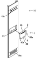
- the humidifier 1 can be thinned as described above, it can be incorporated into a thin plate-like panel 10 having a humidity control function, for example.
- the panel 10 shown in FIGS. 8 and 9 is installed substantially vertically along a wall surface (not shown).
- the panel 10 includes an exhaust port 10b formed on the upper side, an intake port 10a formed on the lower side, and a functional unit (not shown) that contains a functional material such as a humidity control material or a deodorizing agent.
- the panel 10 is configured to take in the air sucked from the air inlet 10a into the functional part, perform humidity adjustment and deodorization, and then exhaust the air conditioned after being exhausted from the air outlet 10b.
- a substantially rectangular housing recess 11 (see FIG. 9) is formed at the front center of the panel 10, and the humidifier 1 is incorporated into the housing recess 11 for use.
- the humidifier 1 can be easily removed by grasping the handles 80a, 80a and pulling forward. According to this, if the humidifier 1 is removed and the cover body 2 is removed, the water supply tank 3 can also be easily removed, and the water injection operation can be easily performed.
- the shape of the humidifier 1 and each member which comprises this, a structure, etc. are not limited to the example of a figure.
- the example which is not provided with the air blower which blows the humidified air here is shown, it is good also as what was provided.
- the installation example of the humidifier 1 is not limited to FIGS. 8 and 9, and may be used by being embedded directly in a wall surface, or the humidifier 1 may be used alone at a favorite place. Needless to say, you can.
Landscapes
- Engineering & Computer Science (AREA)
- Chemical & Material Sciences (AREA)
- Combustion & Propulsion (AREA)
- Mechanical Engineering (AREA)
- General Engineering & Computer Science (AREA)
- Air Humidification (AREA)
Abstract
L'invention concerne un humidificateur équipé d'un réservoir d'eau, d'une plaque de transfert de chaleur, d'une plaque d'absorption d'eau, d'un moyen de chauffage et d'une unité de commande. Le réservoir d'eau est conçu pour accumuler l'eau. La plaque de transfert de chaleur est une plaque en matériau conduisant la chaleur qui est fixée au réservoir d'eau. La plaque d'absorption d'eau est située sur une face de la plaque de transfert de chaleur et est conçue pour absorber et retenir l'eau accumulée dans le réservoir d'eau. Le moyen de chauffage est placé sur l'autre face de la plaque de transfert de chaleur. L'unité de commande est conçue pour commander le moyen de chauffage afin qu'il chauffe, au travers de la plaque de transfert de chaleur, l'eau retenue sur la plaque d'absorption d'eau, ce qui produit de la vapeur d'eau. La plaque d'absorption d'eau comporte une couche piège d'impuretés et une couche absorbant l'eau. La couche piège d'impuretés est conçue pour absorber l'eau accumulée dans le réservoir d'eau et éliminer les impuretés de l'eau absorbée. La couche d'absorption d'eau est conçue de façon à absorber et retenir l'eau dont les impuretés ont été éliminées par la couche piège d'impuretés.
Applications Claiming Priority (4)
| Application Number | Priority Date | Filing Date | Title |
|---|---|---|---|
| JP2011012112A JP5529774B2 (ja) | 2011-01-24 | 2011-01-24 | 加湿器 |
| JP2011012111A JP5820968B2 (ja) | 2011-01-24 | 2011-01-24 | 加湿器 |
| JP2011-012112 | 2011-05-30 | ||
| JP2011-012111 | 2011-05-30 |
Publications (1)
| Publication Number | Publication Date |
|---|---|
| WO2012101877A1 true WO2012101877A1 (fr) | 2012-08-02 |
Family
ID=46580464
Family Applications (1)
| Application Number | Title | Priority Date | Filing Date |
|---|---|---|---|
| PCT/JP2011/074053 Ceased WO2012101877A1 (fr) | 2011-01-24 | 2011-10-19 | Humidificateur |
Country Status (1)
| Country | Link |
|---|---|
| WO (1) | WO2012101877A1 (fr) |
Cited By (2)
| Publication number | Priority date | Publication date | Assignee | Title |
|---|---|---|---|---|
| WO2017103657A1 (fr) * | 2015-12-17 | 2017-06-22 | MIZRAHI AKSIYOTE, Aldo Adolfo | Système et appareil de haute efficacité dans le transfert de masse |
| CN109764460A (zh) * | 2019-01-09 | 2019-05-17 | 青岛海尔空调器有限总公司 | 一种能源系统及控制方法 |
Citations (7)
| Publication number | Priority date | Publication date | Assignee | Title |
|---|---|---|---|---|
| JPS439280Y1 (fr) * | 1964-04-04 | 1968-04-22 | ||
| JPH0367822U (fr) * | 1989-10-23 | 1991-07-03 | ||
| JPH03104142U (fr) * | 1990-02-13 | 1991-10-29 | ||
| JPH0566408U (ja) * | 1992-02-20 | 1993-09-03 | シャープ株式会社 | 加湿機能付電気暖房器 |
| JPH0632936U (ja) * | 1992-05-15 | 1994-04-28 | シルバー株式会社 | 加湿機用スケール捕集材 |
| JPH1026379A (ja) * | 1996-07-09 | 1998-01-27 | Mitsubishi Juko Reinetsu Kizai Kk | 吸水型加熱式加湿装置における吸水エレメント |
| JP2009068732A (ja) * | 2007-09-11 | 2009-04-02 | Daikin Ind Ltd | 加湿機 |
-
2011
- 2011-10-19 WO PCT/JP2011/074053 patent/WO2012101877A1/fr not_active Ceased
Patent Citations (7)
| Publication number | Priority date | Publication date | Assignee | Title |
|---|---|---|---|---|
| JPS439280Y1 (fr) * | 1964-04-04 | 1968-04-22 | ||
| JPH0367822U (fr) * | 1989-10-23 | 1991-07-03 | ||
| JPH03104142U (fr) * | 1990-02-13 | 1991-10-29 | ||
| JPH0566408U (ja) * | 1992-02-20 | 1993-09-03 | シャープ株式会社 | 加湿機能付電気暖房器 |
| JPH0632936U (ja) * | 1992-05-15 | 1994-04-28 | シルバー株式会社 | 加湿機用スケール捕集材 |
| JPH1026379A (ja) * | 1996-07-09 | 1998-01-27 | Mitsubishi Juko Reinetsu Kizai Kk | 吸水型加熱式加湿装置における吸水エレメント |
| JP2009068732A (ja) * | 2007-09-11 | 2009-04-02 | Daikin Ind Ltd | 加湿機 |
Cited By (2)
| Publication number | Priority date | Publication date | Assignee | Title |
|---|---|---|---|---|
| WO2017103657A1 (fr) * | 2015-12-17 | 2017-06-22 | MIZRAHI AKSIYOTE, Aldo Adolfo | Système et appareil de haute efficacité dans le transfert de masse |
| CN109764460A (zh) * | 2019-01-09 | 2019-05-17 | 青岛海尔空调器有限总公司 | 一种能源系统及控制方法 |
Similar Documents
| Publication | Publication Date | Title |
|---|---|---|
| CN214469040U (zh) | 空调扇 | |
| JP3434049B2 (ja) | 吸水型加熱式加湿装置 | |
| JP6367445B2 (ja) | 加湿空気清浄機 | |
| JP7687491B2 (ja) | 空調機 | |
| WO2012101877A1 (fr) | Humidificateur | |
| JP7552649B2 (ja) | 空調機 | |
| JP2019023541A (ja) | 加湿装置 | |
| JP5681974B2 (ja) | 加湿器 | |
| JP5820968B2 (ja) | 加湿器 | |
| JP5529774B2 (ja) | 加湿器 | |
| JP2004347297A (ja) | 加湿装置 | |
| JP2008039327A (ja) | 加湿装置 | |
| KR101728057B1 (ko) | 상부급수형 물탱크를 구비하는 가습기 | |
| KR20110112531A (ko) | 기화 제습식 공조기 | |
| CN2913927Y (zh) | 蒸发型吸水膜加湿器 | |
| JP5630787B2 (ja) | 空気循環パネル | |
| JP2004020074A (ja) | 透湿性エレメント、調湿用複合エレメントおよび調湿装置 | |
| JPS60171337A (ja) | 加湿器 | |
| JP2002257378A (ja) | クーラの排熱風の冷却装置 | |
| JP2007234941A (ja) | 電子機器用ラック、電子機器、電子機器用加湿装置、電子機器における加湿方法 | |
| JP2005083590A (ja) | 加湿フィルター | |
| JP7732616B1 (ja) | 電池パック構造 | |
| CN205655459U (zh) | 空调器 | |
| CN218548624U (zh) | 防凝露装置、电池箱、动力电池及车辆 | |
| JPH02213629A (ja) | 加湿器 |
Legal Events
| Date | Code | Title | Description |
|---|---|---|---|
| 121 | Ep: the epo has been informed by wipo that ep was designated in this application |
Ref document number: 11856825 Country of ref document: EP Kind code of ref document: A1 |
|
| NENP | Non-entry into the national phase |
Ref country code: DE |
|
| 122 | Ep: pct application non-entry in european phase |
Ref document number: 11856825 Country of ref document: EP Kind code of ref document: A1 |