WO2012101904A1 - Dispositif d'éclairage et système d'observation - Google Patents
Dispositif d'éclairage et système d'observation Download PDFInfo
- Publication number
- WO2012101904A1 WO2012101904A1 PCT/JP2011/078236 JP2011078236W WO2012101904A1 WO 2012101904 A1 WO2012101904 A1 WO 2012101904A1 JP 2011078236 W JP2011078236 W JP 2011078236W WO 2012101904 A1 WO2012101904 A1 WO 2012101904A1
- Authority
- WO
- WIPO (PCT)
- Prior art keywords
- light
- wavelength band
- light source
- emitted
- optical axis
- Prior art date
- Legal status (The legal status is an assumption and is not a legal conclusion. Google has not performed a legal analysis and makes no representation as to the accuracy of the status listed.)
- Ceased
Links
Images











Classifications
-
- G—PHYSICS
- G02—OPTICS
- G02B—OPTICAL ELEMENTS, SYSTEMS OR APPARATUS
- G02B21/00—Microscopes
- G02B21/16—Microscopes adapted for ultraviolet illumination ; Fluorescence microscopes
-
- F—MECHANICAL ENGINEERING; LIGHTING; HEATING; WEAPONS; BLASTING
- F21—LIGHTING
- F21V—FUNCTIONAL FEATURES OR DETAILS OF LIGHTING DEVICES OR SYSTEMS THEREOF; STRUCTURAL COMBINATIONS OF LIGHTING DEVICES WITH OTHER ARTICLES, NOT OTHERWISE PROVIDED FOR
- F21V7/00—Reflectors for light sources
-
- A—HUMAN NECESSITIES
- A61—MEDICAL OR VETERINARY SCIENCE; HYGIENE
- A61B—DIAGNOSIS; SURGERY; IDENTIFICATION
- A61B1/00—Instruments for performing medical examinations of the interior of cavities or tubes of the body by visual or photographical inspection, e.g. endoscopes; Illuminating arrangements therefor
- A61B1/06—Instruments for performing medical examinations of the interior of cavities or tubes of the body by visual or photographical inspection, e.g. endoscopes; Illuminating arrangements therefor with illuminating arrangements
- A61B1/0638—Instruments for performing medical examinations of the interior of cavities or tubes of the body by visual or photographical inspection, e.g. endoscopes; Illuminating arrangements therefor with illuminating arrangements providing two or more wavelengths
-
- A—HUMAN NECESSITIES
- A61—MEDICAL OR VETERINARY SCIENCE; HYGIENE
- A61B—DIAGNOSIS; SURGERY; IDENTIFICATION
- A61B1/00—Instruments for performing medical examinations of the interior of cavities or tubes of the body by visual or photographical inspection, e.g. endoscopes; Illuminating arrangements therefor
- A61B1/06—Instruments for performing medical examinations of the interior of cavities or tubes of the body by visual or photographical inspection, e.g. endoscopes; Illuminating arrangements therefor with illuminating arrangements
- A61B1/0646—Instruments for performing medical examinations of the interior of cavities or tubes of the body by visual or photographical inspection, e.g. endoscopes; Illuminating arrangements therefor with illuminating arrangements with illumination filters
-
- A—HUMAN NECESSITIES
- A61—MEDICAL OR VETERINARY SCIENCE; HYGIENE
- A61B—DIAGNOSIS; SURGERY; IDENTIFICATION
- A61B1/00—Instruments for performing medical examinations of the interior of cavities or tubes of the body by visual or photographical inspection, e.g. endoscopes; Illuminating arrangements therefor
- A61B1/06—Instruments for performing medical examinations of the interior of cavities or tubes of the body by visual or photographical inspection, e.g. endoscopes; Illuminating arrangements therefor with illuminating arrangements
- A61B1/0661—Endoscope light sources
- A61B1/0669—Endoscope light sources at proximal end of an endoscope
-
- A—HUMAN NECESSITIES
- A61—MEDICAL OR VETERINARY SCIENCE; HYGIENE
- A61B—DIAGNOSIS; SURGERY; IDENTIFICATION
- A61B1/00—Instruments for performing medical examinations of the interior of cavities or tubes of the body by visual or photographical inspection, e.g. endoscopes; Illuminating arrangements therefor
- A61B1/06—Instruments for performing medical examinations of the interior of cavities or tubes of the body by visual or photographical inspection, e.g. endoscopes; Illuminating arrangements therefor with illuminating arrangements
- A61B1/0661—Endoscope light sources
- A61B1/0684—Endoscope light sources using light emitting diodes [LED]
-
- G—PHYSICS
- G02—OPTICS
- G02B—OPTICAL ELEMENTS, SYSTEMS OR APPARATUS
- G02B23/00—Telescopes, e.g. binoculars; Periscopes; Instruments for viewing the inside of hollow bodies; Viewfinders; Optical aiming or sighting devices
- G02B23/24—Instruments or systems for viewing the inside of hollow bodies, e.g. fibrescopes
- G02B23/2407—Optical details
- G02B23/2461—Illumination
- G02B23/2469—Illumination using optical fibres
-
- G—PHYSICS
- G02—OPTICS
- G02B—OPTICAL ELEMENTS, SYSTEMS OR APPARATUS
- G02B27/00—Optical systems or apparatus not provided for by any of the groups G02B1/00 - G02B26/00, G02B30/00
- G02B27/10—Beam splitting or combining systems
- G02B27/1006—Beam splitting or combining systems for splitting or combining different wavelengths
-
- G—PHYSICS
- G02—OPTICS
- G02B—OPTICAL ELEMENTS, SYSTEMS OR APPARATUS
- G02B27/00—Optical systems or apparatus not provided for by any of the groups G02B1/00 - G02B26/00, G02B30/00
- G02B27/10—Beam splitting or combining systems
- G02B27/14—Beam splitting or combining systems operating by reflection only
- G02B27/141—Beam splitting or combining systems operating by reflection only using dichroic mirrors
-
- G—PHYSICS
- G02—OPTICS
- G02B—OPTICAL ELEMENTS, SYSTEMS OR APPARATUS
- G02B6/00—Light guides; Structural details of arrangements comprising light guides and other optical elements, e.g. couplings
- G02B6/0001—Light guides; Structural details of arrangements comprising light guides and other optical elements, e.g. couplings specially adapted for lighting devices or systems
- G02B6/0005—Light guides; Structural details of arrangements comprising light guides and other optical elements, e.g. couplings specially adapted for lighting devices or systems the light guides being of the fibre type
- G02B6/0006—Coupling light into the fibre
-
- A—HUMAN NECESSITIES
- A61—MEDICAL OR VETERINARY SCIENCE; HYGIENE
- A61B—DIAGNOSIS; SURGERY; IDENTIFICATION
- A61B1/00—Instruments for performing medical examinations of the interior of cavities or tubes of the body by visual or photographical inspection, e.g. endoscopes; Illuminating arrangements therefor
- A61B1/06—Instruments for performing medical examinations of the interior of cavities or tubes of the body by visual or photographical inspection, e.g. endoscopes; Illuminating arrangements therefor with illuminating arrangements
- A61B1/07—Instruments for performing medical examinations of the interior of cavities or tubes of the body by visual or photographical inspection, e.g. endoscopes; Illuminating arrangements therefor with illuminating arrangements using light-conductive means, e.g. optical fibres
-
- G—PHYSICS
- G01—MEASURING; TESTING
- G01N—INVESTIGATING OR ANALYSING MATERIALS BY DETERMINING THEIR CHEMICAL OR PHYSICAL PROPERTIES
- G01N21/00—Investigating or analysing materials by the use of optical means, i.e. using sub-millimetre waves, infrared, visible or ultraviolet light
- G01N21/62—Systems in which the material investigated is excited whereby it emits light or causes a change in wavelength of the incident light
- G01N21/63—Systems in which the material investigated is excited whereby it emits light or causes a change in wavelength of the incident light optically excited
- G01N21/64—Fluorescence; Phosphorescence
- G01N2021/6417—Spectrofluorimetric devices
- G01N2021/6419—Excitation at two or more wavelengths
-
- G—PHYSICS
- G01—MEASURING; TESTING
- G01N—INVESTIGATING OR ANALYSING MATERIALS BY DETERMINING THEIR CHEMICAL OR PHYSICAL PROPERTIES
- G01N21/00—Investigating or analysing materials by the use of optical means, i.e. using sub-millimetre waves, infrared, visible or ultraviolet light
- G01N21/62—Systems in which the material investigated is excited whereby it emits light or causes a change in wavelength of the incident light
- G01N21/63—Systems in which the material investigated is excited whereby it emits light or causes a change in wavelength of the incident light optically excited
- G01N21/64—Fluorescence; Phosphorescence
- G01N21/645—Specially adapted constructive features of fluorimeters
- G01N2021/6463—Optics
- G01N2021/6471—Special filters, filter wheel
-
- G—PHYSICS
- G01—MEASURING; TESTING
- G01N—INVESTIGATING OR ANALYSING MATERIALS BY DETERMINING THEIR CHEMICAL OR PHYSICAL PROPERTIES
- G01N21/00—Investigating or analysing materials by the use of optical means, i.e. using sub-millimetre waves, infrared, visible or ultraviolet light
- G01N21/62—Systems in which the material investigated is excited whereby it emits light or causes a change in wavelength of the incident light
- G01N21/63—Systems in which the material investigated is excited whereby it emits light or causes a change in wavelength of the incident light optically excited
- G01N21/64—Fluorescence; Phosphorescence
- G01N21/645—Specially adapted constructive features of fluorimeters
-
- G—PHYSICS
- G01—MEASURING; TESTING
- G01N—INVESTIGATING OR ANALYSING MATERIALS BY DETERMINING THEIR CHEMICAL OR PHYSICAL PROPERTIES
- G01N2201/00—Features of devices classified in G01N21/00
- G01N2201/06—Illumination; Optics
- G01N2201/061—Sources
Definitions
- the present invention relates to an illumination device and an observation system including the same.
- an illumination device that includes a plurality of light sources that emit light in different wavelength bands, and synthesizes and emits light in different wavelength bands from these light sources by a dichroic mirror (for example, see Patent Documents 1 to 3) ).
- the present invention has been made in view of the above-described circumstances, and an object thereof is to provide an illumination device and an observation system that can emit light having a continuous spectrum and high color rendering properties.
- the present invention employs the following means.
- a first light source that emits light in a first wavelength band, and light in a second wavelength band that has a continuous spectrum in a wider band than the first wavelength band.
- 2 light sources a light combining unit that combines the light of the first wavelength band and the light of the second wavelength band, and a combining ratio adjusting unit that adjusts the combining ratio of the light of each wavelength band by the light combining unit It is an illuminating device provided with.
- the light in the first wavelength band from the first light source and the light in the second wavelength band from the second light source are combined by the light combining unit and emitted.
- the combining ratio adjusting unit adjusts the combining ratio of light in each wavelength band by the light combining unit.
- the present invention when light of a specific wavelength band is to be emitted, the light of the first wavelength band and the light of the second wavelength band are Light in a specific wavelength band can be emitted by adjusting a synthesis ratio with light.
- the light in the second wavelength band that is, the light in the second wavelength band having a continuous spectrum wider than the first wavelength band. Can be injected as it is.
- the light combining unit reflects the light in the first wavelength band and transmits part of the light in the second wavelength band, so that the light in the first wavelength band is transmitted.
- the light of the second wavelength band may be combined, and the combining ratio adjustment unit may insert and remove the light combining unit from the optical axis of the second light source.
- the first light source and / or the second light source is turned on in a state where the light combining unit is disposed on the optical axis of the second light source.
- light of a specific wavelength band can be emitted.
- the second light source is turned on in a state where the light combining unit is removed from the optical axis of the second light source.
- Light in the second wavelength band having a spectrum can be emitted as it is.
- the 3rd light source which emits the light of the 3rd wavelength band which is a part wavelength band of the said 2nd wavelength band is provided,
- the said photosynthesis part is a said 1st wavelength band.
- Light and light in the second wavelength band are reflected, and light in the third wavelength band is transmitted.
- the combining ratio adjusting unit moves the light combining unit around an axis orthogonal to the optical axis of each light source. It is good also as rotating.
- the light combining unit is configured to reflect the light of the first wavelength band from the first light source in the direction of the emission optical axis of the combined light. Rotate around an axis perpendicular to the optical axis of each light source. In this state, by turning on the first light source and / or the third light source, light in a specific wavelength band can be emitted.
- each light source unit is configured to reflect light in the second wavelength band from the second light source in the direction of the optical axis of the synthesized light. Rotate around an axis perpendicular to the optical axis. In this state, by turning on the second light source and the third light source, in the light of the second wavelength band, a broadband continuous spectrum in which a part of the wavelength band is replaced with the light of the third wavelength band. Can be emitted.
- the 3rd light source which emits the light of the 3rd wavelength band which is a wavelength band different from the said 1st wavelength band and the said 2nd wavelength band is provided,
- the filter is a plate-like filter that reflects light in the first wavelength band and light in the third wavelength band and transmits part of the light in the second wavelength band.
- the light combining unit may be rotated about an axis perpendicular to the optical axis of each light source.
- the light of the first wavelength band from the first light source is reflected in the direction of the emission optical axis of the synthesized light.
- the light combining unit is rotated around an axis perpendicular to the optical axis of each light source. In this state, by turning on the first light source and / or the second light source, light in a desired wavelength band can be emitted.
- each of the light combining units is arranged so that the reflection surface of the light combining unit which is a plate-like filter is in a direction along the emission optical axis of the second light source. Rotate around an axis perpendicular to the optical axis of the light source. In this state, by turning on the second light source, the light in the second wavelength band having a broadband and continuous spectrum can be emitted as it is without being reflected by the light combining unit.
- photosynthesis is performed so that light in the third wavelength band from the third light source is reflected in the direction of the emission optical axis of the synthesized light.
- the unit is rotated around an axis perpendicular to the optical axis of each light source. In this state, light in a desired wavelength band can be emitted by turning on the third light source and / or the second light source.
- Said 1st aspect WHEREIN It is good also as lighting each said light source synchronizing with rotation of the said photosynthesis part. By doing in this way, the light of the 1st wavelength band, the light of the 2nd wavelength band, and the light of the 3rd wavelength band can be emitted one by one, and field sequential illumination can be performed.
- the synthesis ratio adjustment unit may finely adjust the rotation angle of the light synthesis unit around the axis perpendicular to the optical axis of the light source according to the wavelength band of the emitted light. Good. By doing so, it is possible to finely adjust the wavelength band of the emitted light using the angle dependency of the light combining unit. Thereby, for example, when it is desired to shift the wavelength of the excitation light by several tens of nanometers depending on the type of the fluorescent reagent, fluorescence observation can be performed by finely adjusting the wavelength of the excitation light (emitted light).
- a second aspect of the present invention is an observation system including the illumination device described above and an image sensor that captures an image of a specimen illuminated by the illumination device. According to the second aspect of the present invention, since the above-described illumination device is provided, it is possible to emit an illumination light according to the specimen, and to take an image of the specimen under an appropriate illumination condition. Accuracy can be improved.
- the white mode it is possible to emit light having a continuous spectrum and high color rendering properties, and it is possible to realize switching to an illumination mode having a high medical effect with a simple configuration. .
- NBI mode 1st Embodiment of this invention
- 10 is a graph showing reflection characteristics of the dichroic mirror in FIG. 9.
- 10 is a graph showing spectral characteristics of light from the first light source of FIG. 9.
- 10 is a graph showing the spectral characteristics of light from the second light source in FIG. 9.
- 10 is a graph showing the spectral characteristics of light from the third light source in FIG. 9.
- the illumination device 1 is applied to, for example, an observation system for observing a living tissue, and as illustrated in FIG. 1, a first light source 10 and a second light source that are arranged in directions in which optical axes are orthogonal to each other. 20, a dichroic mirror (light combining unit) 40 disposed on the intersection of the optical axis of the first light source 10 and the optical axis of the second light source 20, and the optical axis of the second light source 20. And a light guide 43.
- the first light source 10 is an LED that emits light L1 having a relatively short wavelength (light in the first wavelength band) such as a violet color.
- a relatively short wavelength light in the first wavelength band
- lens groups 11 and 12 that make the light L1 from the first light source 10 substantially parallel light are arranged.
- the second light source 20 is an LED that emits light (second wavelength band light) L2 having a continuous spectrum with a relatively wide band such as white.
- lens groups 21 and 22 that make the light L2 from the second light source 20 substantially parallel light are arranged.
- the dichroic mirror 40 has reflection characteristics such as transmitting light in a wavelength band of 500 nm or more and less than 600 nm and reflecting light in a wavelength band of less than 500 nm and 600 nm or more.
- each graph indicates an incident angle to the dichroic mirror 40.
- the dichroic mirror 40 reflects the light L1 emitted from the first light source 10, and among the light L2 emitted from the second light source 20, the dichroic mirror 40 has a wavelength of 500 nm or more and less than 600 nm. It is designed to transmit light in the wavelength band. Further, as shown in FIG. 7, the dichroic mirror 40 is moved in the optical axis direction of the first light source 10 by a moving mechanism (not shown) according to the illumination mode described later, and is on the optical axis of the second light source 20. It is designed to be inserted and removed.
- the illuminating device 1 includes an NBI (Narrow Band Imaging) mode for illuminating light in a specific wavelength band, and WLI (White for illuminating white light).
- NBI Near Band Imaging
- WLI White for illuminating white light
- Light Imaging white light observation
- the dichroic mirror 40 is inserted into and removed from the optical axis of the second light source 20 by a moving mechanism (not shown).
- the NBI mode is the irradiation of light in two narrow wavelength bands that are easily absorbed by hemoglobin in the blood (for example, light in the wavelength band of 390 to 445 nm and light in the wavelength band of 530 to 550 nm).
- This is an illumination mode that can highlight and display capillaries and mucous membrane fine patterns on the surface of the mucosa.
- the WLI mode irradiates white light with a wide wavelength band and is an illumination mode that can perform observation with high color rendering properties.
- the light guide 43 is a light guide rod made of glass or the like, for example, and guides light from the dichroic mirror 40 collected by the lens groups 41 and 42 to the emission end.
- the dichroic mirror 40 is disposed on the optical axis of the second light source 20 as shown in FIG. In this state, the first light source 10 and the second light source 20 are turned on.
- the first light source 10 emits light L1 having a relatively short wavelength such as a violet color.
- the light L1 emitted from the first light source 10 is made into substantially parallel light by the lens groups 11 and 12 and reflected toward the incident end of the light guide 43 by the dichroic mirror 40.
- the dichroic mirror 40 From the second light source 20, light L2 having a continuous spectrum with a relatively wide band such as white is emitted.
- the light L2 emitted from the second light source 20 is made into substantially parallel light by the lens groups 21 and 22 and enters the dichroic mirror 40.
- the dichroic mirror 40 As shown in FIG. 5, a part of the light L2 emitted from the second light source 20 is transmitted in the direction of the incident end of the light guide 43, and the other is reflected.
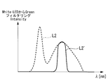
- the dichroic mirror 40 transmits, for example, light L2 ′ in the wavelength band of 500 nm or more and less than 600 nm among the light L2 emitted from the second light source 20, and has wavelength bands of less than 500 nm and 600 nm or more. Reflects light.
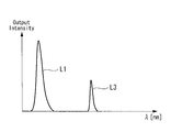
- the light L1 emitted from the first light source 10 and the light L2 emitted from the second light source 20 are 500 nm or more and less than 600 nm as shown in FIG.
- the light L2 ′ in the wavelength band is synthesized.
- the combined light is condensed on the incident end of the light guide 43 by the lens groups 41 and 42, guided to the emission end by the light guide 43, and emitted.
- the dichroic mirror 40 is moved in the optical axis direction of the first light source 10 by a moving mechanism (not shown) and removed from the optical path of the second light source 20. .
- the second light source 20 is turned on.
- the first light source 10 since the light from the first light source 10 is not guided to the incident end of the light guide 43, the first light source 10 may be turned on.
- the second light source 20 emits light L2 having a continuous spectrum with a relatively wide band such as white.
- the light L2 emitted from the second light source 20 is made into substantially parallel light by the lens groups 21 and 22, condensed at the incident end of the light guide 43 by the lens groups 41 and 42, and up to the emission end by the light guide 43. Guided and injected.
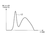
- the light L2 emitted from the second light source 20 that is, white light having a continuous spectrum in a wide band as shown in FIG. 8 can be irradiated, and observation with high color rendering can be performed. .
- the light L1 from the first light source 10 and the light L2 from the second light source 20 are combined by the dichroic filter 40 and emitted.
- light in different wavelength bands can be switched and emitted by moving the dichroic filter 40 in the optical axis direction of the first light source 10 by a moving mechanism (not shown).
- a wavelength band can be switched and light can be inject
- the first light source 10 and / or the second light source 10 and / or the second light source are selected with the NBI mode selected and the dichroic filter 40 disposed on the light L2 axis.
- the light source 20 By turning on the light source 20, light in a specific wavelength band can be emitted.
- the WLI mode is selected, and the second light source 20 is turned on with the dichroic filter 40 removed from the optical axis of the second light source 20. By doing so, it is possible to emit the light L2 having a broadband and continuous spectrum as it is.
- an illumination device according to a second embodiment of the present invention will be described mainly with reference to FIGS.
- the illumination device according to this embodiment is different from the first embodiment in that a third light source 30 is provided in addition to the first light source 10 and the second light source 20.
- a third light source 30 is provided in addition to the first light source 10 and the second light source 20.
- the illumination device 2 includes a first light source 10, a second light source 20, a third light source 30, and light sources arranged in directions in which optical axes are orthogonal to each other. And a light guide 43 disposed on the optical axis of the third light source 30.
- the first light source 10 and the second light source 20 are arranged to face each other, and the third light source 30 has its optical axis directed in a direction orthogonal to the optical axes of the first light source 10 and the second light source 20. Has been placed.
- the first light source 10 is an LED that emits light L1 having a relatively short wavelength (light in the first wavelength band) such as a violet color.
- a relatively short wavelength light in the first wavelength band
- lens groups 11 and 12 that make the light L1 from the first light source 10 substantially parallel light are arranged.
- the second light source 20 is an LED that emits light (second wavelength band light) L2 having a continuous spectrum with a relatively wide band such as white.
- lens groups 21 and 22 that make the light L2 from the second light source 20 substantially parallel light are arranged.
- the third light source 30 is an LED that emits light of an intermediate wavelength such as green (light of the third wavelength band) L3, for example.
- the wavelength band of the light L3 is a part of the wavelength band of the light L2 from the second light source 20.
- lens groups 31 and 32 that make the light L3 from the third light source 30 substantially parallel light are arranged.
- the dichroic mirror 40 has reflection characteristics such as transmitting light in a wavelength band of 500 nm or more and less than 600 nm and reflecting light in a wavelength band of less than 500 nm and 600 nm or more.
- the dichroic mirror 40 reflects the light L1 emitted from the first light source 10 and has a wavelength of 500 nm or more and less than 600 nm among the light L2 emitted from the second light source 20.
- the band light and the light L3 emitted from the third light source 30 are transmitted.
- the dichroic mirror 40 is rotated about an axis (axis perpendicular to the paper surface) perpendicular to the optical axis of each light source by a moving mechanism (not shown) according to an illumination mode to be described later. It has become.
- the illumination device 2 includes an NBI (Narrow Band Imaging) mode for illuminating light in a specific wavelength band, and a WLI (White for illuminating white light).
- NBI Near Band Imaging
- WLI White for illuminating white light
- Light Imaging white light observation
- the dichroic mirror 40 is rotated about an axis perpendicular to the optical axis of each light source by a moving mechanism (not shown).
- the light guide 43 is a light guide rod made of glass or the like, for example, and guides light from the dichroic mirror 40 collected by the lens groups 41 and 42 to the emission end.
- the dichroic mirror 40 is set to an angle that reflects the light L ⁇ b> 1 emitted from the first light source 10 toward the incident end of the light guide 43. In this state, the first light source 10 and the third light source 30 are turned on.
- the first light source 10 emits light L1 having a relatively short wavelength such as a violet color.
- the light L1 emitted from the first light source 10 is made into substantially parallel light by the lens groups 11 and 12 and reflected toward the incident end of the light guide 43 by the dichroic mirror 40.
- the light L3 having an intermediate wavelength such as green is emitted.
- the light L3 emitted from the third light source 30 is made into substantially parallel light by the lens groups 31 and 32, passes through the dichroic mirror 40, and enters the incident end of the light guide 43.
- the light L1 emitted from the first light source 10 and the light L3 emitted from the third light source 30 are synthesized by the dichroic mirror 40 having such reflection characteristics.
- the combined light is condensed on the incident end of the light guide 43 by the lens groups 41 and 42, guided to the emission end by the light guide 43, and emitted.
- the dichroic mirror 40 is rotated around an axis perpendicular to the optical axis of each light source by a moving mechanism (not shown), and the light L2 emitted from the second light source 20 Is set to an angle at which the light is reflected toward the incident end of the light guide 43.
- the second light source 20 and the third light source 30 are turned on.
- the dichroic mirror 40 transmits, for example, light having a wavelength band of 500 nm or more and less than 600 nm among the light L2 emitted from the second light source 20, and light L2 having a wavelength band of less than 500 nm and 600 nm or more. 'Reflect.
- the light L3 emitted from the third light source 30 and the light L2 emitted from the second light source 20 are less than 500 nm and 600 nm or more.
- the light in the wavelength band is synthesized.
- the combined light is condensed on the incident end of the light guide 43 by the lens groups 41 and 42, guided to the emission end by the light guide 43, and emitted.
- the light L2 'in the wavelength band of 500 nm or more and less than 600 nm in the light L2 emitted from the second light source 20 can be replaced with the light L3 emitted from the third light source 30 and emitted.
- the human eye feels that the brightness is greatly improved by increasing the intensity of light of an intermediate wavelength such as green. Therefore, by increasing the intensity of the light L3 from the third light source 30, it is possible to irradiate white light having a bright, broadband and continuous spectrum, and the observation accuracy can be improved.
- the NBI mode is selected, and the light L1 from the first light source 10 is emitted as combined light.
- the dichroic filter 40 is rotated about an axis perpendicular to the optical axis of each light source so as to reflect in the axial direction. In this state, by turning on the first light source 10 and / or the third light source 30, light in a specific wavelength band can be emitted.
- the dichroic filter 40 is selected so that the WLI mode is selected and the light L2 from the second light source 20 is reflected in the direction of the emission optical axis of the combined light. Are rotated around an axis perpendicular to the optical axis of each light source. In this state, by turning on the second light source 20 and the third light source 30, a part of the wavelength band in the light L2 from the second light source 20 is replaced with the light L3 from the third light source 30. Therefore, it is possible to emit synthetic light having a continuous spectrum that is bright and broadband.
- an illuminating device according to a third embodiment of the present invention will be described mainly with reference to FIGS.
- the illumination device is different from the above-described embodiments in that it has an MI (Molecular Imaging) mode using IR light in addition to the NBI mode and the WLI mode.
- MI Magnetic Imaging
- description of points that are the same as those of the above-described embodiments will be omitted, and differences will be mainly described.
- MI Molecular Image Observation
- PET-CT PET-CT
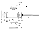
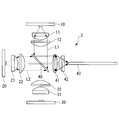
- the illumination device 3 includes a first light source 10, a second light source 20, a third light source 30, and light sources arranged in directions in which optical axes are orthogonal to each other. And a light guide 43 disposed on the optical axis of the second light source 20.
- the dichroic mirror (light combining unit) 40 disposed on the intersection of the optical axes of the second light source 20.
- the first light source 10 and the third light source 30 are disposed to face each other, and the second light source 20 has its optical axis directed in a direction orthogonal to the optical axes of the first light source 10 and the third light source 30. Has been placed.
- the first light source 10 is an LED that emits light L1 having a relatively short wavelength (light in the first wavelength band) such as a violet color.
- a relatively short wavelength light in the first wavelength band
- lens groups 11 and 12 that make the light L1 from the first light source 10 substantially parallel light are arranged.
- the second light source 20 is an LED that emits light (second wavelength band light) L2 having a continuous spectrum with a relatively wide band such as white.
- lens groups 21 and 22 that make the light L2 from the second light source 20 substantially parallel light are arranged.
- the third light source 30 is, for example, an LED that emits IR light (light in the third wavelength band) L3.
- the light L3 is light having a wavelength band different from that of the light L2 from the second light source 20.
- lens groups 31 and 32 that make the light L3 from the third light source 30 substantially parallel light are arranged.
- the dichroic mirror 40 has reflection characteristics such that, for example, light in a wavelength band of 500 nm or more and less than 600 nm is transmitted, and light in a wavelength band of less than 500 nm or 600 nm or more is reflected.
- each graph indicates an incident angle to the dichroic mirror 40.
- the dichroic mirror 40 reflects the light L1 emitted from the first light source 10 and has a wavelength of 500 nm or more and less than 600 nm among the light L2 emitted from the second light source 20.
- the band light and the light L3 emitted from the third light source 30 are transmitted.
- the dichroic mirror 40 is rotated about an axis (axis perpendicular to the paper surface) perpendicular to the optical axis of each light source by a moving mechanism (not shown) according to an illumination mode to be described later. It has become.
- the illumination device 3 includes an NBI (Narrow Band Imaging) mode for illuminating light in a specific wavelength band, and a WLI (White for illuminating white light).
- NBI Near Band Imaging
- WLI White for illuminating white light
- Light Imaging (white light observation) mode and MI Molecular Imaging: molecular image observation) mode are provided.
- the dichroic mirror 40 is rotated about an axis perpendicular to the optical axis of each light source by a moving mechanism (not shown).
- the light guide 43 is a light guide rod made of glass or the like, for example, and guides light from the dichroic mirror 40 collected by the lens groups 41 and 42 to the emission end.
- the dichroic mirror 40 is rotated around an axis perpendicular to the optical axis of each light source by a moving mechanism (not shown), and the reflection surface thereof is the optical axis of the second light source 20. It arrange
- the second light source 20 emits light L2 having a continuous spectrum with a relatively wide band such as white.
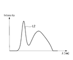
- the light L2 emitted from the second light source 20 is made into substantially parallel light by the lens groups 21 and 22, condensed at the incident end of the light guide 43 by the lens groups 41 and 42, and up to the emission end by the light guide 43. Guided and injected. Accordingly, it is possible to irradiate the light L2 emitted from the second light source 20, that is, white light having a continuous spectrum in a wide band as shown in FIG. 23, and observation with high color rendering properties can be performed. .
- the dichroic mirror 40 is set to an angle at which the light L1 emitted from the first light source 10 is reflected toward the incident end of the light guide 43. In this state, the first light source 10 and the second light source 20 are turned on.
- the first light source 10 emits light L1 having a relatively short wavelength such as a violet color.
- the light L1 emitted from the first light source 10 is made into substantially parallel light by the lens groups 11 and 12 and reflected toward the incident end of the light guide 43 by the dichroic mirror 40.
- the dichroic mirror 40 From the second light source 20, light L2 having a continuous spectrum with a relatively wide band such as white is emitted.
- the light L2 emitted from the second light source 20 is made into substantially parallel light by the lens groups 21 and 22 and enters the dichroic mirror 40.
- the dichroic mirror 40 As shown in FIG. 25, a part of the light L2 emitted from the second light source 20 is transmitted in the direction of the incident end of the light guide 43, and the other is reflected.
- the dichroic mirror 40 transmits, for example, light L2 ′ in the wavelength band of 500 nm or more and less than 600 nm among the light L2 emitted from the second light source 20, and has wavelength bands of less than 500 nm and 600 nm or more. Reflects light.
- the light L2 ′ in the wavelength band is synthesized.
- the combined light is condensed on the incident end of the light guide 43 by the lens groups 41 and 42, guided to the emission end by the light guide 43, and emitted.
- the dichroic mirror 40 is set to an angle that reflects the light L3 emitted from the third light source 30 toward the incident end of the light guide 43. In this state, the second light source 20 and the third light source 30 are turned on.
- the third light source 30 From the third light source 30, light L3 having a relatively short wavelength such as IR light is emitted.
- the light L3 emitted from the third light source 30 is made into substantially parallel light by the lens groups 31 and 32 and is reflected by the dichroic mirror 40 toward the incident end of the light guide 43.
- the dichroic mirror 40 transmits, for example, light L2 ′ in the wavelength band of 500 nm or more and less than 600 nm among the light L2 emitted from the second light source 20, and has wavelength bands of less than 500 nm and 600 nm or more. Reflects light.
- the light L3 emitted from the third light source 30 and the light L2 emitted from the second light source 20 are 500 nm or more and less than 600 nm as shown in FIG.
- the light L2 ′ in the wavelength band is synthesized.
- the combined light is condensed on the incident end of the light guide 43 by the lens groups 41 and 42, guided to the emission end by the light guide 43, and emitted.
- the light L3 emitted from the third light source 30 is used as excitation light
- the light L2 ′ in the wavelength band of 500 nm or more and less than 600 nm among the light L2 emitted from the second light source 20 is the reference light.
- specific molecules such as glucose and various proteins
- the NBI mode is selected and the first light source
- the dichroic filter 40 is rotated about an axis perpendicular to the optical axis of each light source so that the light L1 from 10 is reflected in the direction of the optical axis of the combined light. In this state, by turning on the first light source 10 and / or the second light source 20, light in a desired wavelength band can be emitted.
- the WLI mode is selected, and the reflection surface of the dichroic filter 40 that is a plate-like filter is in a direction along the emission optical axis of the second light source 20.
- the dichroic filter 40 is rotated about an axis perpendicular to the optical axis of each light source. In this state, by turning on the second light source 20, the light L ⁇ b> 2 having a broadband and continuous spectrum can be emitted as it is without being reflected by the dichroic filter 40.
- the MI mode is selected, and the light L3 from the third light source 30 is emitted as synthesized light.
- the dichroic filter 40 is rotated around an axis perpendicular to the optical axis of each light source so as to reflect in the optical axis direction. In this state, by turning on the third light source 30 and / or the second light source 20, light in a desired wavelength band can be emitted.
- the rotation of the dichroic filter 40 and the lighting of each light source may be synchronized.
- the spectra of the light L1 emitted from the first light source 10, the light L2 emitted from the second light source 20, and the light L3 emitted from the third light source 30 are complementary to each other. Therefore, by sequentially turning on each light source in synchronization with the rotation of the dichroic filter 40, as shown in FIG. 30, light having a broadband and continuous spectrum can be emitted as superimposed light.
- the WLI mode, NBI mode, and MI mode can be switched sequentially at a high speed, it is possible to perform illumination such as high-speed plane sequential.
- the subject can be imaged in three illumination modes. Therefore, NBI mode and MI mode are superimposed on the WLI mode image by image processing, or switching display is performed at high speed. Can be done.
- the stationary angle of the dichroic filter 40 may be finely adjusted.
- the static angle of the dichroic filter 40 is not limited to the three patterns of 45 °, 0 °, and ⁇ 45 ° as described above. For example, it is good also as 43 degrees and 40 degrees.
- the wavelength of the G band cut out from the white light (the light L2 emitted from the second light source 20) can be arbitrarily set.
- violet light and green light are used in both NBI mode and AFI mode, but the irradiation wavelength is slightly different (the center wavelength of the G band in NBI mode is 10 nm shorter than that of AFI).
- the stationary angle of the filter between the NBI mode and the AFI mode an optimum wavelength in the G band can be provided.
- the spectral characteristics of the dichroic filter 40 are set as shown in FIG. 31, and the stationary angle of the dichroic filter 40 is changed as shown in FIG. 33, so that the wavelength of light from each light source is as shown in FIGS. Can be shifted.
- the stationary angle of the dichroic filter 40 is changed, and the wavelength of the excitation light (emitted light) is finely adjusted. It can be carried out.
- each light source has been described as an independent LED.
- a multi-chip LED module in which chips having different wavelengths are packaged may be used. Thereby, the freedom degree of the spectrum in output light (combined light) can be increased, and the light of a more desired band can be obtained.
- a dichroic filter has been described as a specific example of the light combining unit, for example, a dichroic prism or the like may be used.
Landscapes
- Physics & Mathematics (AREA)
- Health & Medical Sciences (AREA)
- Life Sciences & Earth Sciences (AREA)
- Optics & Photonics (AREA)
- Surgery (AREA)
- Engineering & Computer Science (AREA)
- General Physics & Mathematics (AREA)
- Animal Behavior & Ethology (AREA)
- Biophysics (AREA)
- Pathology (AREA)
- Biomedical Technology (AREA)
- Heart & Thoracic Surgery (AREA)
- Medical Informatics (AREA)
- Molecular Biology (AREA)
- Nuclear Medicine, Radiotherapy & Molecular Imaging (AREA)
- General Health & Medical Sciences (AREA)
- Public Health (AREA)
- Veterinary Medicine (AREA)
- Radiology & Medical Imaging (AREA)
- Microelectronics & Electronic Packaging (AREA)
- Astronomy & Astrophysics (AREA)
- Chemical & Material Sciences (AREA)
- Analytical Chemistry (AREA)
- General Engineering & Computer Science (AREA)
- Endoscopes (AREA)
- Instruments For Viewing The Inside Of Hollow Bodies (AREA)
- Optical Elements Other Than Lenses (AREA)
- Microscoopes, Condenser (AREA)
- Eye Examination Apparatus (AREA)
Abstract
La présente invention se rapporte à un dispositif d'éclairage et à un système d'observation grâce auxquels il est possible d'émettre de la lumière présentant de bonnes propriétés de rendu de couleur ayant un spectre contigu. Un dispositif d'éclairage (1) est utilisé, comprenant : une première source de lumière (10) qui émet de la lumière (L1) d'une première bande de longueur d'onde ; une seconde source de lumière (20) qui émet de la lumière (L2) d'une seconde bande de longueur d'onde qui est plus large que la première bande de longueur d'onde et qui a un spectre contigu ; un miroir dichroïque (40) qui est positionné au croisement de l'axe optique de la première source de lumière (10) et de l'axe optique de la seconde source de lumière (20) et qui est introduit dans l'axe optique de la seconde source de lumière (20) et retiré de celui-ci ; et un guide de lumière (43) qui est positionné sur l'axe optique de la seconde source de lumière (20).
Priority Applications (4)
| Application Number | Priority Date | Filing Date | Title |
|---|---|---|---|
| JP2012543810A JP5174290B2 (ja) | 2011-01-28 | 2011-12-07 | 照明装置および観察システム |
| CN201180042584.3A CN103097809B (zh) | 2011-01-28 | 2011-12-07 | 照明装置和观察系统 |
| EP11856800.5A EP2589858B1 (fr) | 2011-01-28 | 2011-12-07 | Dispositif d'éclairage et système d'observation |
| US13/613,803 US8547427B2 (en) | 2011-01-28 | 2012-09-13 | Illumination device and observation system |
Applications Claiming Priority (2)
| Application Number | Priority Date | Filing Date | Title |
|---|---|---|---|
| JP2011016945 | 2011-01-28 | ||
| JP2011-016945 | 2011-07-22 |
Related Child Applications (1)
| Application Number | Title | Priority Date | Filing Date |
|---|---|---|---|
| US13/613,803 Continuation US8547427B2 (en) | 2011-01-28 | 2012-09-13 | Illumination device and observation system |
Publications (1)
| Publication Number | Publication Date |
|---|---|
| WO2012101904A1 true WO2012101904A1 (fr) | 2012-08-02 |
Family
ID=46580488
Family Applications (1)
| Application Number | Title | Priority Date | Filing Date |
|---|---|---|---|
| PCT/JP2011/078236 Ceased WO2012101904A1 (fr) | 2011-01-28 | 2011-12-07 | Dispositif d'éclairage et système d'observation |
Country Status (5)
| Country | Link |
|---|---|
| US (1) | US8547427B2 (fr) |
| EP (1) | EP2589858B1 (fr) |
| JP (1) | JP5174290B2 (fr) |
| CN (1) | CN103097809B (fr) |
| WO (1) | WO2012101904A1 (fr) |
Cited By (8)
| Publication number | Priority date | Publication date | Assignee | Title |
|---|---|---|---|---|
| WO2013045934A2 (fr) | 2011-09-28 | 2013-04-04 | Procure Therapeutics Limited | Compositions comprenant des agents qui inhibent la neuropiline et la tolloïde de type 2 |
| JP2016000073A (ja) * | 2014-06-11 | 2016-01-07 | 富士フイルム株式会社 | 内視鏡用光源装置及び内視鏡システム |
| JP2016158837A (ja) * | 2015-02-27 | 2016-09-05 | 富士フイルム株式会社 | 内視鏡光源装置、内視鏡システム、及び内視鏡光源装置の作動方法 |
| JP2016202774A (ja) * | 2015-04-28 | 2016-12-08 | 富士フイルム株式会社 | 内視鏡用光源装置及び内視鏡システム |
| JPWO2018003263A1 (ja) * | 2016-06-27 | 2019-04-18 | ソニー株式会社 | 観察装置、および観察装置の制御方法 |
| JP2019122865A (ja) * | 2019-05-10 | 2019-07-25 | 富士フイルム株式会社 | 内視鏡光源装置、内視鏡システム、及び内視鏡光源装置の作動方法 |
| WO2020144983A1 (fr) * | 2019-01-07 | 2020-07-16 | ソニー株式会社 | Dispositif de source de lumière et dispositif d'affichage d'image |
| CN112515616A (zh) * | 2016-02-19 | 2021-03-19 | Hoya株式会社 | 内窥镜用光源装置以及内窥镜系统 |
Families Citing this family (18)
| Publication number | Priority date | Publication date | Assignee | Title |
|---|---|---|---|---|
| WO2013121616A1 (fr) * | 2012-02-17 | 2013-08-22 | オリンパスメディカルシステムズ株式会社 | Dispositif endoscopique |
| CN104102079B (zh) * | 2013-04-02 | 2016-08-03 | 扬明光学股份有限公司 | 光源模组及投影装置 |
| CN103631020A (zh) * | 2013-12-18 | 2014-03-12 | 吴震 | 发光装置、受激发光装置和投影显示装置 |
| EP2942651A1 (fr) * | 2014-05-06 | 2015-11-11 | DirectPhotonics Industries GmbH | Dispositif de filtrage de coupure optique et dispositif de génération de faisceau laser |
| CN106999029A (zh) | 2015-05-28 | 2017-08-01 | 奥林巴斯株式会社 | 光源装置 |
| WO2017041044A1 (fr) | 2015-09-02 | 2017-03-09 | Inscopix, Inc. | Systèmes et procédés d'imagerie couleur |
| US12251272B2 (en) | 2015-11-05 | 2025-03-18 | Inscopix, Inc. | Systems and methods for optogenetic imaging using semi-kinematic coupling |
| JP2018533768A (ja) | 2015-11-05 | 2018-11-15 | インスコピックス, インコーポレイテッド | 光遺伝学撮像のためのシステムおよび方法 |
| WO2017216883A1 (fr) * | 2016-06-14 | 2017-12-21 | オリンパス株式会社 | Dispositif endoscopique |
| CN107510431A (zh) * | 2016-06-17 | 2017-12-26 | 奥斯奥鹏外科产品股份公司 | 一种高分子医学内窥镜 |
| AT15723U1 (de) * | 2016-08-30 | 2018-04-15 | Binder Co Ag | Vorrichtung zum Detektieren von Objekten in einem Materialstrom |
| DE112017006226T5 (de) * | 2016-12-12 | 2019-09-05 | Olympus Corporation | Lichtquelleneinrichtung |
| KR101877921B1 (ko) * | 2017-04-26 | 2018-07-12 | 인더스마트 주식회사 | 광학 어셈블리 및 이를 포함하는 내시경용 광원장치 |
| DE102019102361B4 (de) * | 2019-01-30 | 2020-09-10 | T.Q. Optoelectronics Co., Ltd. | Lichtquellenmodul eines endoskops |
| DE102019115276A1 (de) | 2019-06-06 | 2020-12-10 | Karl Storz Se & Co. Kg | Lichtquelle und System für die und Verfahren zur Fluoreszenzdiagnose |
| CN111338069A (zh) * | 2020-04-13 | 2020-06-26 | 合肥登特菲医疗设备有限公司 | 一种口腔显微镜照明装置 |
| DE102020122282A1 (de) * | 2020-08-26 | 2022-03-03 | Hoya Corporation | Beleuchtungssystem |
| US12222486B2 (en) | 2020-12-28 | 2025-02-11 | Bioaces (Shanghai) Life Science Co., Ltd | Light source apparatus, microscopic device, optical detection device and optical detection method |
Citations (5)
| Publication number | Priority date | Publication date | Assignee | Title |
|---|---|---|---|---|
| JPH0756134A (ja) * | 1993-08-18 | 1995-03-03 | Kodo Eizo Gijutsu Kenkyusho:Kk | 液晶投写型表示装置 |
| JP2005250059A (ja) * | 2004-03-03 | 2005-09-15 | Hitachi Ltd | 光源装置及びそれを用いた投射型映像表示装置 |
| JP2008176083A (ja) | 2007-01-19 | 2008-07-31 | Sony Corp | 画像表示装置 |
| JP2008292547A (ja) | 2007-05-22 | 2008-12-04 | Sony Corp | 画像表示用光学ユニット、マイクロレンズアレイおよび画像表示装置 |
| JP2009086057A (ja) | 2007-09-27 | 2009-04-23 | Citizen Electronics Co Ltd | 投写型表示装置 |
Family Cites Families (11)
| Publication number | Priority date | Publication date | Assignee | Title |
|---|---|---|---|---|
| DE10356826B4 (de) * | 2003-12-05 | 2021-12-02 | Leica Microsystems Cms Gmbh | Rastermikroskop |
| JP4459662B2 (ja) * | 2004-03-05 | 2010-04-28 | Hoya株式会社 | 調節機構 |
| US7497581B2 (en) * | 2004-03-30 | 2009-03-03 | Goldeneye, Inc. | Light recycling illumination systems with wavelength conversion |
| JP2006204341A (ja) * | 2005-01-25 | 2006-08-10 | Pentax Corp | 光源装置 |
| US7339660B1 (en) * | 2006-11-29 | 2008-03-04 | Satake Usa, Inc. | Illumination device for product examination |
| JP4395792B2 (ja) * | 2007-01-29 | 2010-01-13 | セイコーエプソン株式会社 | プロジェクタ |
| CN101470337B (zh) * | 2007-12-27 | 2012-03-14 | 红蝶科技(深圳)有限公司 | 一种嵌入有投影机模块的移动设备 |
| JP2009201940A (ja) * | 2008-02-29 | 2009-09-10 | Hoya Corp | 内視鏡光源システム、内視鏡光源装置、内視鏡プロセッサ、および内視鏡ユニット |
| US8977085B2 (en) * | 2008-11-04 | 2015-03-10 | The University Of Queensland | Surface structure modification |
| CN201464788U (zh) * | 2009-04-24 | 2010-05-12 | 红蝶科技(深圳)有限公司 | 一种高光效的微型投影光学引擎 |
| JP5283572B2 (ja) * | 2009-06-08 | 2013-09-04 | 三菱電機株式会社 | 映像表示装置 |
-
2011
- 2011-12-07 CN CN201180042584.3A patent/CN103097809B/zh active Active
- 2011-12-07 JP JP2012543810A patent/JP5174290B2/ja active Active
- 2011-12-07 WO PCT/JP2011/078236 patent/WO2012101904A1/fr not_active Ceased
- 2011-12-07 EP EP11856800.5A patent/EP2589858B1/fr not_active Not-in-force
-
2012
- 2012-09-13 US US13/613,803 patent/US8547427B2/en active Active
Patent Citations (5)
| Publication number | Priority date | Publication date | Assignee | Title |
|---|---|---|---|---|
| JPH0756134A (ja) * | 1993-08-18 | 1995-03-03 | Kodo Eizo Gijutsu Kenkyusho:Kk | 液晶投写型表示装置 |
| JP2005250059A (ja) * | 2004-03-03 | 2005-09-15 | Hitachi Ltd | 光源装置及びそれを用いた投射型映像表示装置 |
| JP2008176083A (ja) | 2007-01-19 | 2008-07-31 | Sony Corp | 画像表示装置 |
| JP2008292547A (ja) | 2007-05-22 | 2008-12-04 | Sony Corp | 画像表示用光学ユニット、マイクロレンズアレイおよび画像表示装置 |
| JP2009086057A (ja) | 2007-09-27 | 2009-04-23 | Citizen Electronics Co Ltd | 投写型表示装置 |
Non-Patent Citations (1)
| Title |
|---|
| See also references of EP2589858A4 |
Cited By (13)
| Publication number | Priority date | Publication date | Assignee | Title |
|---|---|---|---|---|
| WO2013045934A2 (fr) | 2011-09-28 | 2013-04-04 | Procure Therapeutics Limited | Compositions comprenant des agents qui inhibent la neuropiline et la tolloïde de type 2 |
| EP2765141A1 (fr) | 2011-09-28 | 2014-08-13 | The University of York | Compositions comprenant des agents qui inhibent la neurophiline et tolloïde de type 2 |
| JP2016000073A (ja) * | 2014-06-11 | 2016-01-07 | 富士フイルム株式会社 | 内視鏡用光源装置及び内視鏡システム |
| JP2016158837A (ja) * | 2015-02-27 | 2016-09-05 | 富士フイルム株式会社 | 内視鏡光源装置、内視鏡システム、及び内視鏡光源装置の作動方法 |
| JP2016202774A (ja) * | 2015-04-28 | 2016-12-08 | 富士フイルム株式会社 | 内視鏡用光源装置及び内視鏡システム |
| CN112515614A (zh) * | 2016-02-19 | 2021-03-19 | Hoya株式会社 | 内窥镜用光源装置以及内窥镜系统 |
| CN112515616A (zh) * | 2016-02-19 | 2021-03-19 | Hoya株式会社 | 内窥镜用光源装置以及内窥镜系统 |
| JPWO2018003263A1 (ja) * | 2016-06-27 | 2019-04-18 | ソニー株式会社 | 観察装置、および観察装置の制御方法 |
| WO2020144983A1 (fr) * | 2019-01-07 | 2020-07-16 | ソニー株式会社 | Dispositif de source de lumière et dispositif d'affichage d'image |
| JPWO2020144983A1 (ja) * | 2019-01-07 | 2021-11-25 | ソニーグループ株式会社 | 光源装置及び画像表示装置 |
| US11796900B2 (en) | 2019-01-07 | 2023-10-24 | Sony Group Corporation | Light source device and image display device |
| JP7424316B2 (ja) | 2019-01-07 | 2024-01-30 | ソニーグループ株式会社 | 光源装置及び画像表示装置 |
| JP2019122865A (ja) * | 2019-05-10 | 2019-07-25 | 富士フイルム株式会社 | 内視鏡光源装置、内視鏡システム、及び内視鏡光源装置の作動方法 |
Also Published As
| Publication number | Publication date |
|---|---|
| JPWO2012101904A1 (ja) | 2014-06-30 |
| EP2589858B1 (fr) | 2016-06-29 |
| US20130113911A1 (en) | 2013-05-09 |
| EP2589858A4 (fr) | 2013-12-04 |
| CN103097809B (zh) | 2014-09-17 |
| US8547427B2 (en) | 2013-10-01 |
| CN103097809A (zh) | 2013-05-08 |
| EP2589858A1 (fr) | 2013-05-08 |
| JP5174290B2 (ja) | 2013-04-03 |
Similar Documents
| Publication | Publication Date | Title |
|---|---|---|
| JP5174290B2 (ja) | 照明装置および観察システム | |
| JP6965334B2 (ja) | 低侵襲手術システム内のカメラの作動方法 | |
| JP5443802B2 (ja) | 蛍光観察装置 | |
| US6477403B1 (en) | Endoscope system | |
| JP6394374B2 (ja) | 照明装置、照明方法及び観察装置 | |
| AU2006260405A1 (en) | Endoscope | |
| JP7675242B2 (ja) | 蛍光薬剤用内視鏡照明システム | |
| US10327622B2 (en) | Endoscope | |
| US20230221539A1 (en) | Surgical microscope having an illumination apparatus | |
| JP6394373B2 (ja) | 照明装置、照明方法及び観察装置 | |
| EP3206560A1 (fr) | Système d'imagerie médicale, dispositif d'éclairage, et procédé | |
| WO2019100450A1 (fr) | Système d'endoscope multifonctionnel | |
| JP2002065602A (ja) | 照明光学系及び内視鏡装置 | |
| JP2012157383A (ja) | 内視鏡装置 | |
| JP2012078504A (ja) | 照明装置および観察システム | |
| CN105705074B (zh) | 内窥镜系统 | |
| CN114468950A (zh) | 混合照明的自体荧光腹腔镜 | |
| KR102747043B1 (ko) | 다중 영상 내시경 시스템 | |
| JP6687071B2 (ja) | 照明装置、照明方法及び観察装置 | |
| JP2003153850A (ja) | 内視鏡用撮像装置 | |
| JP6973549B2 (ja) | 観察システム及び観察システムの制御方法 | |
| WO2022168424A1 (fr) | Système de microscope à usage chirurgical | |
| JP2021096998A (ja) | 光源モジュール | |
| US20260020754A1 (en) | Illumination device, imaging device having an illumination device, imaging system, method for generating illumination light, and method for operating an imaging device | |
| JP6687072B2 (ja) | 照明装置、照明方法及び観察装置 |
Legal Events
| Date | Code | Title | Description |
|---|---|---|---|
| WWE | Wipo information: entry into national phase |
Ref document number: 201180042584.3 Country of ref document: CN |
|
| 121 | Ep: the epo has been informed by wipo that ep was designated in this application |
Ref document number: 11856800 Country of ref document: EP Kind code of ref document: A1 |
|
| WWE | Wipo information: entry into national phase |
Ref document number: 2012543810 Country of ref document: JP |
|
| WWE | Wipo information: entry into national phase |
Ref document number: 2011856800 Country of ref document: EP |
|
| NENP | Non-entry into the national phase |
Ref country code: DE |