WO2012102169A1 - Procédé d'échange de manchon chauffant et outil d'échange de manchon chauffant pour machine de moulage par injection verticale - Google Patents
Procédé d'échange de manchon chauffant et outil d'échange de manchon chauffant pour machine de moulage par injection verticale Download PDFInfo
- Publication number
- WO2012102169A1 WO2012102169A1 PCT/JP2012/051094 JP2012051094W WO2012102169A1 WO 2012102169 A1 WO2012102169 A1 WO 2012102169A1 JP 2012051094 W JP2012051094 W JP 2012051094W WO 2012102169 A1 WO2012102169 A1 WO 2012102169A1
- Authority
- WO
- WIPO (PCT)
- Prior art keywords
- heating cylinder
- plate
- heating
- injection molding
- molding machine
- Prior art date
- Legal status (The legal status is an assumption and is not a legal conclusion. Google has not performed a legal analysis and makes no representation as to the accuracy of the status listed.)
- Ceased
Links
Images


Classifications
-
- B—PERFORMING OPERATIONS; TRANSPORTING
- B22—CASTING; POWDER METALLURGY
- B22D—CASTING OF METALS; CASTING OF OTHER SUBSTANCES BY THE SAME PROCESSES OR DEVICES
- B22D17/00—Pressure die casting or injection die casting, i.e. casting in which the metal is forced into a mould under high pressure
- B22D17/20—Accessories: Details
- B22D17/2015—Means for forcing the molten metal into the die
- B22D17/2023—Nozzles or shot sleeves
-
- B—PERFORMING OPERATIONS; TRANSPORTING
- B29—WORKING OF PLASTICS; WORKING OF SUBSTANCES IN A PLASTIC STATE IN GENERAL
- B29C—SHAPING OR JOINING OF PLASTICS; SHAPING OF MATERIAL IN A PLASTIC STATE, NOT OTHERWISE PROVIDED FOR; AFTER-TREATMENT OF THE SHAPED PRODUCTS, e.g. REPAIRING
- B29C45/00—Injection moulding, i.e. forcing the required volume of moulding material through a nozzle into a closed mould; Apparatus therefor
- B29C45/17—Component parts, details or accessories; Auxiliary operations
- B29C45/176—Exchanging the injection unit or parts thereof
-
- B—PERFORMING OPERATIONS; TRANSPORTING
- B29—WORKING OF PLASTICS; WORKING OF SUBSTANCES IN A PLASTIC STATE IN GENERAL
- B29C—SHAPING OR JOINING OF PLASTICS; SHAPING OF MATERIAL IN A PLASTIC STATE, NOT OTHERWISE PROVIDED FOR; AFTER-TREATMENT OF THE SHAPED PRODUCTS, e.g. REPAIRING
- B29C45/00—Injection moulding, i.e. forcing the required volume of moulding material through a nozzle into a closed mould; Apparatus therefor
- B29C45/17—Component parts, details or accessories; Auxiliary operations
- B29C45/72—Heating or cooling
- B29C45/74—Heating or cooling of the injection unit
Definitions
- the present invention relates to a heating cylinder replacement method and a heating cylinder replacement jig of a vertical injection molding machine, and more particularly to means for easily and safely attaching and detaching a heating cylinder to and from a heating cylinder holding plate provided in an injection unit.
- the vertical injection molding machine is attached in such a manner that the heating cylinder is suspended from the heating cylinder holding plate provided in the injection unit. Therefore, in order to remove the heating cylinder from the heating cylinder holding plate, the heating cylinder It is necessary to remove the bolt that fixes the heating cylinder to the heating cylinder holding plate while supporting and to remove the bolt, and to transfer the heating cylinder to a required working position or storage position.
- the heating cylinder since the heating cylinder is heavy, performing the bolt removing operation while supporting the heating tube with human power increases the physical burden on the operator and is severe to the operator.
- the heating cylinder may be dropped without being supported or may collide with other equipment, which is also a safety issue. Of course, the same problem occurs when the heating cylinder is attached to the heating cylinder holding plate.
- a holding device that moves up and down integrally with the screw driving device is detachably provided below a mounting plate that is a heating cylinder holding plate for mounting the screw driving device so as to be movable up and down.
- a technology has been proposed in which the plasticizing unit separated from the screw driving device is held by the holding device in a suspended state and slid to a position separated from the machine center position of the vertical injection molding machine (for example, a patent Reference 1).
- Patent Document 1 when the plasticizing unit is attached to or detached from the screw driving device, the plasticizing unit is held by the holding device and transferred to a predetermined position. There is no need to support it manually, and work can be done efficiently and safely.
- Patent Document 1 uses two L-shaped rails arranged opposite to each other as a holding device, and engages an engaging step formed on the plasticizing unit on the horizontal side of the rail. Therefore, it can be applied only to a specific plasticizing unit in which a predetermined engagement step portion is formed at a predetermined position, and cannot be universally applied to attachment / detachment of a plasticizing unit having no engagement step portion. There's a problem.
- the present invention has been made in view of the above-described points, and the object of the present invention is to be applied universally to existing vertical injection molding machines and to attach and detach the plasticizing unit even for non-experts.
- An object of the present invention is to provide a heating cylinder replacement method and a heating cylinder replacement jig capable of easily and efficiently performing work.
- the present invention relates to a heating cylinder replacement method, a die plate having an upper mold attached to the lower surface side, and a heating cylinder holding plate provided to be movable up and down with respect to the die plate. And a nozzle touch motor for moving the heating cylinder holding plate up and down, a heating cylinder whose upper end is detachably held on the heating cylinder holding plate, and a rotatable and vertically movable housing in the heating cylinder.
- a screw a metering electric servo motor that rotationally drives the screw, a linear motion plate that is vertically movable with respect to the die plate, and detachably holds an upper end of the screw, and the linear motion plate
- An injection electric servomotor that moves the screw up and down via a control device, a control device that controls driving of each motor, and a display device that can display a required display screen as appropriate.
- the control device causes the display device to drive the nozzle touch motor and to perform the heating cylinder replacement treatment for the die plate.
- the heating for the heating cylinder holding plate including a procedure for attaching and detaching a tool, a procedure for holding the heating cylinder to the heating cylinder replacement jig, and a procedure for transferring the heating cylinder held by the heating cylinder replacement jig
- the cylinder attachment / detachment procedure is displayed, and the operator performs the attachment / detachment operation of the heating cylinder with respect to the heating cylinder holding plate in accordance with the attachment / detachment operation procedure displayed on the display device.
- the heating cylinder attaching / detaching procedure with respect to the heating cylinder holding plate is displayed on the display device, and the worker performs the attaching / detaching operation of the heating cylinder according to the attaching / detaching procedure displayed on the display device, special knowledge and skill are obtained. Even an operator who does not have the need to replace the heating cylinder can perform the replacement operation of the heating cylinder at any time and smoothly. Further, in this case, when the heating tube attaching / detaching work procedure using the heating tube replacement jig is displayed on the display device, the operator performs the attaching / detaching operation of the heating tube using the required heating tube replacing jig. An operator can hold a heavy heating cylinder with a heating cylinder replacement jig and does not need to support this manually, so that the heating cylinder can be attached and detached easily and safely.
- the heating cylinder replacement jig is slidable on the slider body that is bolted to the upper surface of the die plate and the slider body. It has an attached slider plate and a cylindrical heating tube insertion holding portion fixed to the upper surface of the slider plate.
- the tip of the heating tube removed from the heating tube holding plate is moved by moving the heating tube insertion holding portion to just below the heating tube suspended from the heating tube holding plate. Can be inserted and held in the heating cylinder insertion holding section, and from that state, the heating cylinder is formed into a vertical injection molding by sliding the slider plate with the heating cylinder insertion holding section fixed to the slider body. It can be moved safely and easily to the side of the machine.
- the heating cylinder replacement jig of this configuration holds the heating cylinder by inserting the tip of the heating cylinder into the heating cylinder insertion holding section provided on the slider plate, so that the heating cylinder is specially processed. This is not necessary, and can be applied universally to replacement work of a heating cylinder having a general configuration.
- the heating cylinder replacement method for the vertical injection molding machine having the above-described configuration
- the heating cylinder is inserted and held by the side of the vertical injection molding machine.
- the slider plate is slid with respect to the slider body, and the heating cylinder held by the heating cylinder insertion holding part is placed below the heating cylinder holding plate.
- the heating cylinder When the heating cylinder is transferred to a predetermined position and the heating cylinder is removed from the heating cylinder holding plate, the tip of the heating cylinder removed from the heating cylinder holding plate is inserted into the heating cylinder insertion holding section, and then the slider plate Is slid with respect to the slider body, and the heating cylinder held by the heating cylinder insertion holding portion is transferred to a predetermined position on the side of the vertical injection molding machine.
- the heating cylinder can be transferred from one predetermined position to another predetermined position simply by sliding the slider plate with respect to the slider body, so that the heating cylinder can be easily replaced. be able to.
- the control device when the control device receives a drive command for the nozzle touch motor from an operator, the control device drives the nozzle touch motor. Controlling, raising or lowering the tip of the heating cylinder to an appropriate position that does not interfere with the heating cylinder replacement jig, and stopping at the appropriate position.
- the heating cylinder holding plate (heating cylinder) is first attached to the tip of the heating cylinder. Retract to a position where it does not interfere with the heating cylinder replacement jig, set the heating cylinder replacement jig on the die plate, and then hold the heating cylinder on the heating cylinder replacement jig (heating cylinder holding plate) Must be advanced to a predetermined position where the tip of the heating cylinder does not interfere with the heating cylinder replacement jig.
- the heating cylinder holding plate When the heating cylinder is attached to the heating cylinder holding plate, the heating cylinder holding plate is first retracted to a position where the end of the heating cylinder does not interfere with the heating cylinder holding plate, and the heating cylinder replacement jig (heating cylinder) is attached. After moving to just below the heating tube mounting part of the heating tube holding plate, the heating tube holding plate is moved to a predetermined position where the end of the heating tube does not interfere with the heating tube holding plate in order to bring the heating tube holding plate closer to the heating tube. Need to move forward.
- the heating cylinder holding plate (heating cylinder) is automatically moved to the appropriate position described above at each stage during the attaching / detaching operation, the operator visually observes the nozzle touch. Since there is no need to adjust the drive of the motor, the replacement operation of the heating cylinder can be performed easily and quickly.
- the present invention relates to a heating cylinder replacement jig, a slider body that is bolted to the upper surface of a die plate provided in a vertical injection molding machine, and is slidable on the slider body. And a cylindrical heating tube insertion holding portion fixed to the upper surface of the slider plate.
- the heating cylinder can be held and transferred by inserting the tip of the heating cylinder into the heating cylinder insertion holding section provided in the slider plate, so that the heating cylinder can be attached to and detached from the heating cylinder holding plate.
- it since it is not necessary to apply special processing to the heating cylinder, it can be applied universally to replacement work of a heating cylinder having a general configuration.
- the procedure for attaching / detaching the heating cylinder to / from the heating cylinder holding plate is displayed on the display device, and the operator performs the attaching / detaching operation of the heating cylinder according to the attachment / detachment procedure displayed on the display device. Even an operator having no knowledge or skill can replace the heating cylinder, and the replacement operation of the heating cylinder can be performed smoothly and at any time.
- the required heating tube replacement jig is used to attach and detach the heating cylinder, there is no need to manually support a heavy heating cylinder, reducing the burden on the operator, and making the heating cylinder easy to attach and detach. And can be safe.
- a heating cylinder replacement jig includes a slider main body bolted to the upper surface of a die plate provided in a vertical injection molding machine, a slider plate slidably provided on the slider main body, and the slider plate And a cylindrical heating tube insertion holding portion fixed to the upper surface of the heating tube, the heating tube can be held and transferred by inserting the leading end of the heating tube into the heating tube insertion holding portion.
- the attaching / detaching operation of the heating cylinder with respect to the plate can be facilitated, and since the heating cylinder need not be specially processed, the versatility of the jig can be enhanced.
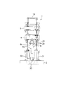
- the upper surface of the die plate 2 in which the injection unit 1 configured in a vertical pattern is positioned at the top of the mold opening / closing unit configured in a vertical pattern. are attached via a hollow base bracket 3.
- An upper mold (not shown) is attached to the lower surface side of the die plate 2.
- the injection unit 1 is arranged opposite to each other, and the heating cylinder holding plate 4 and the linear motion plate 5 that move up and down with respect to the die plate 2 within a predetermined range, and the heating cylinder unit suspended from the heating cylinder holding plate 4 6, a nozzle touch ball screw mechanism 7 that moves up and down the heating cylinder unit 6 and an electric servo motor 8 for nozzle touch, and is housed in the heating cylinder unit 6 so as to be rotatable and movable up and down, and the base end portion is a direct acting plate 5, a screw 9 rotatably held by the motor 5, a metering electric servomotor 10 that rotationally drives the screw 9, an injection ball screw mechanism 11 that moves the linear motion plate 5 and the screw 9 forward and backward, and an electric servomotor for injection 12.
- the heating cylinder unit 6 includes a heating cylinder 6a, a nozzle 6b attached to the distal end portion thereof, and a hopper block 6c attached to the proximal end portion of the heating cylinder 6a.
- the nozzle 6b is opened on the die plate 2. Through the heating cylinder insertion hole 2a, it is pressed against a resin injection hole provided in an upper mold (not shown).
- the injection ball screw mechanism 11 includes a nut body 11a that is rotatably attached to the heating cylinder holding plate 4, and a screw shaft 11b that is screwed into the nut body 11a.
- the electric servo motor 8 is used as a nozzle touch motor, but a normal electric motor may be used instead. In the present specification, these may be collectively referred to as “nozzle touch motor”.
- the driving / stopping of the motors 8, 10, 12 provided in the injection unit 1 is controlled by a control device 21 provided in the vertical injection molding machine.
- a display device 22 is attached to the control device 21, and the setting conditions of the injection unit 1, the driving condition, the attaching / detaching procedure of the heating cylinder unit 6 with respect to the heating cylinder holding plate 4 and the like are displayed.
- a nut body 7a of a ball screw mechanism 7 for nozzle touch is rotatably held on the heating cylinder holding plate 4, and a screw shaft 7b of the ball screw mechanism 7 is screwed to the nut body 7a.
- Three ball screw mechanisms 7 are provided at an angular interval of 120 ° with the heating cylinder unit 6 as the center.
- the lower ends of the screw shafts 7b of the ball screw mechanisms 7 are fixed to the upper surface side of the base bracket 3, respectively.
- the upper end side of the screw shaft 7 b is fixed to the connection bracket 13.
- the screw shaft 7b of the ball screw mechanism 7 is formed so that the spiral groove for the ball screw mechanism and the linear groove for the ball spline mechanism cross, and the screw shaft 7b has the function of the screw shaft.
- Each screw shaft 7b is connected to a spline outer cylinder 14 fixed to the heating cylinder holding plate 4 and a spline outer cylinder 15 fixed to a linear motion plate 5 to be described later by ball spline coupling.
- the cylinder holding plate 4 and the linear motion plate 5 are movable in the axial direction of the screw shaft 7b and cannot be rotated.
- the rotation of the nozzle touch servomotor 8 is transmitted to a driven pulley 7c that rotates integrally with the nut body 7a of the ball screw mechanism 7, and the nut body 7a rotates, so that the heating cylinder holding plate 4 is integrated with the nut body 7a. Is driven down or up.
- the nozzle is reciprocated between a position where the nozzle abuts a resin injection hole of the upper mold (not shown) and a predetermined position where the nozzle does not interfere with a heating cylinder replacement jig described later.
- the linear motion plate 5 is equipped with a metering electric servo motor 10, and the rotation of the metering electric servo motor 10 is transmitted to a driven pulley 16 fixed to a rotating member that rotates integrally with the screw 9. Thereby, the screw 9 is rotationally driven.
- An electric servomotor 12 for injection is also attached to the linear motion plate 5, and the rotation of the electric servomotor 12 for injection is fixed to the heating cylinder holding plate 4 and the nut body 11 a. It is transmitted to the linear motion plate 5 through an injection ball screw mechanism 11 that is constituted by a screw shaft 11b that is screwed to the linear motion plate 11 and that is rotatably held by the linear motion plate 5. That is, the rotation of the injection electric servomotor 12 is transmitted to the driven pulley 17 that rotates integrally with the screw shaft 11b that constitutes the ball screw mechanism 11, and when the screw shaft 11b rotates, the heating cylinder holding plate 4 that is stopped at a predetermined position. The screw shaft 11b is linearly moved with respect to the nut body, whereby the linear motion plate 5 and the screw 9 are integrally driven downward or upward.
- the vertical injection molding machine including the injection unit 1 having such a configuration rotates the nozzle touch electric servomotor 8 in a predetermined direction during the molding operation to lower the heating cylinder holding plate 4.
- the nozzle provided at the tip is pressed against the resin injection hole of the upper mold, and this pressing state is maintained by the nozzle touch electric servomotor 8.
- the metering electric servo motor 10 is rotated in a predetermined direction to rotationally drive the screw 9 in a predetermined direction, and the resin material supplied to the proximal end side of the heating cylinder unit 6 is kneaded and plasticized.
- the screw 9 is fed to the distal end side of the screw 9 while being turned, and the screw 9 is retracted (raised) together with the linear motion plate 5 as molten resin is stored on the distal end side of the screw 9. Then, while controlling the pressure (back pressure) applied to the molten resin at this time by the electric servomotor 12 for injection, the screw 9 is rotated and retracted along with the rotation, and one shot is applied to the tip side of the screw 9. When the amount of molten resin is stored, rotation of the metering electric servo motor 10 is stopped.
- the electric servomotor 12 for injection is rotationally driven in a predetermined direction, and the screw 9 is rapidly moved forward (rapidly lowered) together with the linear motion plate 5, and the mold clamped from the nozzle 6b.
- the molten resin is injected and filled into the mold cavity.
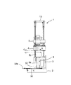
- the heating cylinder replacement jig 30 of this example linearly transfers the held heating cylinder unit 6, and includes a slider body 31 formed in a frame shape having a predetermined shape, A slider plate 32 that is slidably held by the slider body 31 and a cylindrical heating tube insertion holding portion 33 that is fixed to the upper surface of the slider plate 32 are provided.
- the slider body 31 includes a lower plate 31a of a predetermined size formed in a substantially square shape, a spacer 31b disposed on a long side portion of the lower plate 31a, a connecting plate 31c for connecting between end portions of the spacer 31b, and the slider.
- a fixing plate 31d for fixing the main body 31 to the die plate 2 is provided, and these members are integrated using bolts 31e.
- the slider plate 32 is provided at one end of the sliding portion 32a and a sliding portion 32a that is slidably mounted in a space defined by the upper surface of the lower plate 31a and the inner surface of the spacer 31b.
- the heating cylinder insertion holding part 33 is attached to the upper surface of the sliding part 32a. As the heating cylinder insertion / holding portion 33, a heating cylinder unit 6 to be replaced can be easily inserted at the tip, and the inserted heating cylinder unit 6 has an appropriate inner diameter so as not to be excessively shaken. Is used.
- the control device 21 provided in the vertical injection molding machine starts up and a predetermined menu screen (not shown) is displayed on the display device 22. .
- a predetermined menu screen (not shown) is displayed on the display device 22.
- “exchange” is selected from this menu screen.
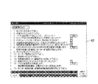
- the replacement screen 40 shown in FIG. 5 is displayed on the display device 22.
- display fields for a mold opening / closing position, a mold thickness, a nozzle, a clamping force, a screw advance, a screw retract, an exchange mold open 1, an exchange mold open 2, an exchange mold closed, an ejector advance, and an ejector retract Is displayed.
- an automatic tightening button is also displayed as function buttons.
- an automatic mold thickness moving button is also displayed as function buttons.
- the replacement screen 40 displays a selection screen for removing the heating tube or setting the heating tube. Appears.
- the heating cylinder removal screen 41 shown in FIG. 5 is displayed on the display device 22. The worker performs the removal operation of the heating cylinder unit 6 while referring to the heating cylinder removal screen 41 displayed on the display device 22.
- the worker removes the screw, heater, nozzle and cooling hose according to the description of “1. Did you remove the screw, heater, nozzle and cooling hose?” Displayed on the first screen of the heating cylinder removal screen 41. Perform the work, and after completing the work, check the check box displayed on the right side of the entry field.
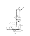
- the worker follows the description of “2. Is the heating cylinder replacement jig set and inserted?” Displayed on the second display of the heating cylinder removal screen 41, and the heating cylinder replacement jig for the die plate 2. As shown in FIGS. 7 to 11, the heating cylinder insertion holding portion 33 is disposed immediately below the heating cylinder unit 6. After completing the work, check the check box displayed in the right column of the entry column.
- the operator displays “3. Nozzle moves forward to a predetermined position before touching the slider.
- the motor automatically stops after reaching the predetermined position. Confirm the description of ".”
- the start button displayed on the right side of the description column.
- the nozzle touch electric servomotor 8 rotates in a predetermined direction, and as shown in FIG. 8, the tip of the heating cylinder unit 6 is lowered to a predetermined position where it does not contact the bottom surface of the heating cylinder insertion holding portion 33. .
- the operator displays the ninth display on the heating cylinder removal screen 41 “9. Treatment to the nozzle retract limit. Are you sure?
- the motor automatically stops after reaching the retract limit position”.
- the start button displayed on the right side of the entry field.
- the nozzle touch electric servomotor 8 reverses and the heating cylinder holding plate 4 rises to the retreat limit position, and as shown in FIG. 10, the base end of the heating cylinder unit 6 and the lower surface of the heating cylinder holding plate 4 A required clearance d is formed between the two.
- the operator confirms the description of “10. Pull out the slider completely and remove the heating cylinder” displayed on the tenth of the heating cylinder removal screen 41, and Holding the handle 32b, as shown in FIG. 11, the slider plate 32 is pulled out along the slider body 31, and the heating cylinder unit 6 held by the heating cylinder insertion holding portion 33 is moved to the vertical injection molding machine side. Pull out to the side. Thereby, it becomes possible to transfer the heating cylinder unit 6 to a predetermined storage place using, for example, a chain block.
- the heating cylinder replacement new button on the replacement screen 40 displayed on the display device 22 is pressed to remove the heating cylinder on the replacement screen 40 or After displaying the selection screen of the heating cylinder set, the heating cylinder set is selected.
- the display unit 22 displays the heating tube setting screen 42 shown in FIG. 6, so that the operator performs the setting operation of the heating tube unit 6 while referring to the heating tube setting screen 42.
- the operator confirms the description of “1.
- the nozzle touch electric servo motor 8 can be started and stopped.
- the operator heats the die plate 2 in accordance with the description of “6. Did you set the heating cylinder replacement jig and pull it out?” Displayed on the sixth of the heating cylinder setting screen 42.
- the cylinder replacement jig 30 is attached, and the heating cylinder insertion holding portion 33 is pulled out to the side portion of the vertical injection molding machine.
- a check is put in the check column displayed on the heating cylinder setting screen 42.
- the operator replaces the heating cylinder in accordance with the description of “7. Did you correctly set and insert the heating cylinder in the heating cylinder replacement jig” displayed on the seventh display on the heating cylinder setting screen 42.
- the tip of the heating cylinder unit 6 integrated with the hopper block is inserted into the heating cylinder insertion holding portion 33 of the jig 30.
- a check is put in the check column displayed on the heating cylinder setting screen 42.
- the operator displays “8. Nozzle moves forward to a predetermined position before touching the slider.
- the motor automatically stops after reaching the predetermined position. Confirm the description of ".”
- the nozzle touch electric servomotor 8 rotates in a predetermined direction, and the heating cylinder holding plate 4 is lowered to a predetermined position where the heating cylinder unit 6 can be attached (see FIG. 8).
- the operator confirms the description of “11. Enter the replacement mode” displayed on the eleventh of the heating cylinder setting screen 42 and operates the operation panel provided in the vertical injection molding machine.
- the drive mode of the nozzle touch electric servomotor 8 is switched to the replacement mode.
- the operator confirms the description of “12. Press the heating cylinder replacement mode / continuation button” displayed on the twelfth of the heating cylinder setting screen 42, and the replacement screen 40 displayed on the display device 22. Press the heating tube replacement continuation button. Thereby, it becomes possible to reverse the nozzle touch electric servomotor 8 and raise the heating cylinder holding plate 4.
- the operator confirms the description of “14. Retreat to the nozzle retract limit.
- the motor automatically stops after reaching the retract limit position” displayed on the 14th screen of the heating cylinder setting screen 42. , Press the start button displayed on the right side of the entry field.
- the nozzle touch electric servomotor 8 rotates in a predetermined direction and rises to a predetermined position where the heating tube replacement jig 30 can be removed (see FIG. 7).
- a procedure for attaching / detaching the heating cylinder unit 6 to / from the heating cylinder holding plate 4 is displayed on the display device 22, and an operator follows the attaching / detaching procedure displayed on the display device 22. Therefore, even an operator who does not have special knowledge or skill can replace the heating cylinder unit 6. Further, since the replacement operation of the heating cylinder unit 6 is performed using the heating cylinder replacement jig 30, the operator can hold the heavy heating cylinder unit 6 with the heating cylinder replacement jig 30, and the heating cylinder Since it is not necessary to support the unit 6 manually, the attaching / detaching operation of the heating cylinder unit 6 can be easily and safely performed.
- exchange method of the heating cylinder unit 6 formed by integrating the heating cylinder 6a and the hopper block 6b was demonstrated, the summary of this invention is not limited to this,
- the heating cylinder 6a In a vertical injection molding machine of a type in which is directly attached to the heating cylinder holding plate 4, it can be directly applied to the method of replacing the heating cylinder 6a.
Landscapes
- Engineering & Computer Science (AREA)
- Mechanical Engineering (AREA)
- Manufacturing & Machinery (AREA)
- Injection Moulding Of Plastics Or The Like (AREA)
- Moulds For Moulding Plastics Or The Like (AREA)
Abstract
La présente invention se rapporte à un procédé et à un outil d'échange de manchon chauffant qui peuvent généralement s'appliquer à des machines de moulage par injection verticale existantes, et grâce auxquels même une personne sans expérience peut facilement et efficacement fixer/retirer une unité de plastification. Au moment d'une opération de fixation/retrait d'un manchon chauffant (6a) sur/depuis une plaque de maintien (4) de manchon chauffant, un dispositif de commande (21) sert à afficher une procédure de fixation/retrait du manchon chauffant (6b) sur/depuis la plaque de maintien (4) de manchon chauffant sur un dispositif d'affichage (22), la procédure comprenant une procédure d'entraînement d'un servomoteur à commande électrique pour un contact de buse, une procédure de fixation/retrait d'un outil d'échange (30) de manchon chauffant sur/depuis une plaque à matrices (2), une procédure de maintien du manchon chauffant (6a) par l'outil d'échange (30) de manchon chauffant, et une procédure de transfert du manchon chauffant (6a) maintenu par l'outil d'échange de manchon chauffant. Un opérateur effectue la fixation/le retrait du manchon chauffant (6a) sur/depuis la plaque de maintien (4) de manchon chauffant conformément à la procédure de fixation/retrait affichée sur le dispositif d'affichage (22).
Priority Applications (1)
| Application Number | Priority Date | Filing Date | Title |
|---|---|---|---|
| CN201280006752.8A CN103347673B (zh) | 2011-01-28 | 2012-01-19 | 立式注射成型机的加热筒更换方法及加热筒更换夹具 |
Applications Claiming Priority (2)
| Application Number | Priority Date | Filing Date | Title |
|---|---|---|---|
| JP2011016642A JP5631228B2 (ja) | 2011-01-28 | 2011-01-28 | 竪型射出成形機の加熱筒交換方法及び加熱筒交換治具 |
| JP2011-016642 | 2011-01-28 |
Publications (1)
| Publication Number | Publication Date |
|---|---|
| WO2012102169A1 true WO2012102169A1 (fr) | 2012-08-02 |
Family
ID=46580741
Family Applications (1)
| Application Number | Title | Priority Date | Filing Date |
|---|---|---|---|
| PCT/JP2012/051094 Ceased WO2012102169A1 (fr) | 2011-01-28 | 2012-01-19 | Procédé d'échange de manchon chauffant et outil d'échange de manchon chauffant pour machine de moulage par injection verticale |
Country Status (3)
| Country | Link |
|---|---|
| JP (1) | JP5631228B2 (fr) |
| CN (1) | CN103347673B (fr) |
| WO (1) | WO2012102169A1 (fr) |
Cited By (1)
| Publication number | Priority date | Publication date | Assignee | Title |
|---|---|---|---|---|
| CN113118392A (zh) * | 2021-04-14 | 2021-07-16 | 苏州三信机器制造有限公司 | 制芯车间用智能化取芯控制方法、装置及系统 |
Families Citing this family (2)
| Publication number | Priority date | Publication date | Assignee | Title |
|---|---|---|---|---|
| JP5745906B2 (ja) * | 2011-03-30 | 2015-07-08 | 東洋機械金属株式会社 | 縦型射出成形機 |
| JP7684067B2 (ja) * | 2021-03-29 | 2025-05-27 | Toyoイノベックス株式会社 | 竪型射出成形機 |
Citations (4)
| Publication number | Priority date | Publication date | Assignee | Title |
|---|---|---|---|---|
| JPH0259914U (fr) * | 1988-10-24 | 1990-05-01 | ||
| JP3696754B2 (ja) * | 1999-06-11 | 2005-09-21 | 株式会社日本製鋼所 | 竪型射出成形機の可塑化ユニット脱着ガイド機構及び脱着ガイド方法 |
| JP2007069571A (ja) * | 2005-09-09 | 2007-03-22 | Toyo Mach & Metal Co Ltd | 縦型射出成形機の全高調整方法 |
| JP2010105330A (ja) * | 2008-10-31 | 2010-05-13 | Fanuc Ltd | 生産切替え機能を有する射出成形機の制御装置 |
Family Cites Families (3)
| Publication number | Priority date | Publication date | Assignee | Title |
|---|---|---|---|---|
| CN2905412Y (zh) * | 2006-03-14 | 2007-05-30 | 华东理工大学 | 一种加热筒体可移动的螺杆挤出机 |
| CN101746036A (zh) * | 2008-12-09 | 2010-06-23 | 上海金发科技发展有限公司 | 一种更换塑料挤出机螺筒的装置 |
| CN101791851A (zh) * | 2010-03-19 | 2010-08-04 | 昆山科信橡塑机械有限公司 | 推拉式双螺杆挤出机 |
-
2011
- 2011-01-28 JP JP2011016642A patent/JP5631228B2/ja not_active Expired - Fee Related
-
2012
- 2012-01-19 CN CN201280006752.8A patent/CN103347673B/zh not_active Expired - Fee Related
- 2012-01-19 WO PCT/JP2012/051094 patent/WO2012102169A1/fr not_active Ceased
Patent Citations (4)
| Publication number | Priority date | Publication date | Assignee | Title |
|---|---|---|---|---|
| JPH0259914U (fr) * | 1988-10-24 | 1990-05-01 | ||
| JP3696754B2 (ja) * | 1999-06-11 | 2005-09-21 | 株式会社日本製鋼所 | 竪型射出成形機の可塑化ユニット脱着ガイド機構及び脱着ガイド方法 |
| JP2007069571A (ja) * | 2005-09-09 | 2007-03-22 | Toyo Mach & Metal Co Ltd | 縦型射出成形機の全高調整方法 |
| JP2010105330A (ja) * | 2008-10-31 | 2010-05-13 | Fanuc Ltd | 生産切替え機能を有する射出成形機の制御装置 |
Cited By (1)
| Publication number | Priority date | Publication date | Assignee | Title |
|---|---|---|---|---|
| CN113118392A (zh) * | 2021-04-14 | 2021-07-16 | 苏州三信机器制造有限公司 | 制芯车间用智能化取芯控制方法、装置及系统 |
Also Published As
| Publication number | Publication date |
|---|---|
| JP5631228B2 (ja) | 2014-11-26 |
| CN103347673A (zh) | 2013-10-09 |
| CN103347673B (zh) | 2015-11-25 |
| JP2012153110A (ja) | 2012-08-16 |
Similar Documents
| Publication | Publication Date | Title |
|---|---|---|
| JP5631228B2 (ja) | 竪型射出成形機の加熱筒交換方法及び加熱筒交換治具 | |
| US20070154648A1 (en) | Method and apparatus for spraying release agent in die casting machine | |
| EP3590678B1 (fr) | Machine de moulage par injection | |
| EP2735421A2 (fr) | Appareil de démoulage un produit moulé en résine et procédé de démoulage de produit moulé en résine | |
| JP6848586B2 (ja) | 2プレート式射出装置及びスクリュ引き抜き方法 | |
| JP7723823B2 (ja) | 加熱筒交換治具および竪型射出成形機の加熱筒交換方法 | |
| JP5495829B2 (ja) | スクリュー式射出装置及びその分解組立方法 | |
| CN204487393U (zh) | 一种全自动高效喷砂除飞边设备 | |
| CN110315702B (zh) | 注射成形机的控制装置及注射成形机的控制方法 | |
| JP5888738B2 (ja) | 洗浄方法 | |
| JP2018167452A (ja) | 射出成形機 | |
| JP3635080B2 (ja) | ゴムホースの自動脱型装置 | |
| JP5069502B2 (ja) | 射出成形機 | |
| JP4977500B2 (ja) | 射出成形機 | |
| JP2006076229A (ja) | オンラインブレンド射出成形機の可塑化装置取付け方法 | |
| CN210818201U (zh) | 一种便于调节的水嘴焊接装置 | |
| JP3997435B1 (ja) | 竪型射出成形機の射出装置及び竪型射出成形機の制御方法 | |
| KR100958973B1 (ko) | 래들의 탑노즐 장착장치 | |
| CN110653604A (zh) | 一种军用开密码锁工具旋转头装配设备 | |
| CN216579245U (zh) | 一种基于超声振动的高精度热熔机 | |
| JP6183708B2 (ja) | 型締装置 | |
| CN106401507B (zh) | 一种磁力旋转油井管钳及其控制系统 | |
| CN223950938U (zh) | 一种石英侧板钉子粘结机 | |
| CN223276563U (zh) | 一种可旋转点胶固化的设备 | |
| CN219006901U (zh) | 一种管状类注塑制品夹取设备 |
Legal Events
| Date | Code | Title | Description |
|---|---|---|---|
| 121 | Ep: the epo has been informed by wipo that ep was designated in this application |
Ref document number: 12738766 Country of ref document: EP Kind code of ref document: A1 |
|
| NENP | Non-entry into the national phase |
Ref country code: DE |
|
| 122 | Ep: pct application non-entry in european phase |
Ref document number: 12738766 Country of ref document: EP Kind code of ref document: A1 |