WO2012102278A1 - Corps absorbant acoustique et mur d'isolation acoustique équipé dudit corps - Google Patents
Corps absorbant acoustique et mur d'isolation acoustique équipé dudit corps Download PDFInfo
- Publication number
- WO2012102278A1 WO2012102278A1 PCT/JP2012/051471 JP2012051471W WO2012102278A1 WO 2012102278 A1 WO2012102278 A1 WO 2012102278A1 JP 2012051471 W JP2012051471 W JP 2012051471W WO 2012102278 A1 WO2012102278 A1 WO 2012102278A1
- Authority
- WO
- WIPO (PCT)
- Prior art keywords
- sound
- absorbing material
- plate member
- sound absorbing
- edge
- Prior art date
- Legal status (The legal status is an assumption and is not a legal conclusion. Google has not performed a legal analysis and makes no representation as to the accuracy of the status listed.)
- Ceased
Links
Images









Classifications
-
- E—FIXED CONSTRUCTIONS
- E01—CONSTRUCTION OF ROADS, RAILWAYS, OR BRIDGES
- E01F—ADDITIONAL WORK, SUCH AS EQUIPPING ROADS OR THE CONSTRUCTION OF PLATFORMS, HELICOPTER LANDING STAGES, SIGNS, SNOW FENCES, OR THE LIKE
- E01F8/00—Arrangements for absorbing or reflecting air-transmitted noise from road or railway traffic
- E01F8/0005—Arrangements for absorbing or reflecting air-transmitted noise from road or railway traffic used in a wall type arrangement
- E01F8/0088—Suspended, e.g. ropes or mesh
-
- E—FIXED CONSTRUCTIONS
- E04—BUILDING
- E04B—GENERAL BUILDING CONSTRUCTIONS; WALLS, e.g. PARTITIONS; ROOFS; FLOORS; CEILINGS; INSULATION OR OTHER PROTECTION OF BUILDINGS
- E04B1/00—Constructions in general; Structures which are not restricted either to walls, e.g. partitions, or floors or ceilings or roofs
- E04B1/62—Insulation or other protection; Elements or use of specified material therefor
- E04B1/74—Heat, sound or noise insulation, absorption, or reflection; Other building methods affording favourable thermal or acoustical conditions, e.g. accumulating of heat within walls
- E04B1/82—Heat, sound or noise insulation, absorption, or reflection; Other building methods affording favourable thermal or acoustical conditions, e.g. accumulating of heat within walls specifically with respect to sound only
- E04B1/8209—Heat, sound or noise insulation, absorption, or reflection; Other building methods affording favourable thermal or acoustical conditions, e.g. accumulating of heat within walls specifically with respect to sound only sound absorbing devices
-
- G—PHYSICS
- G10—MUSICAL INSTRUMENTS; ACOUSTICS
- G10K—SOUND-PRODUCING DEVICES; METHODS OR DEVICES FOR PROTECTING AGAINST, OR FOR DAMPING, NOISE OR OTHER ACOUSTIC WAVES IN GENERAL; ACOUSTICS NOT OTHERWISE PROVIDED FOR
- G10K11/00—Methods or devices for transmitting, conducting or directing sound in general; Methods or devices for protecting against, or for damping, noise or other acoustic waves in general
- G10K11/16—Methods or devices for protecting against, or for damping, noise or other acoustic waves in general
Definitions
- the present invention relates to a sound absorber that can be used indoors or outdoors to efficiently exhibit a sound absorbing effect, and a sound insulation wall using the same.
- a sound absorber As such a sound absorber, a sound absorbing material made of a fibrous material, a breathable protective material placed on both sides of the sound absorbing material, and a peripheral portion of the laminated breathable protective material and the sound absorbing material are mounted. And what consists of the frame for integrating these three members is already proposed (for example, refer to patent documents 1).
- the sound absorber is composed of many parts such as a sound absorbing material, two air-permeable protective materials, and a frame, which is disadvantageous in terms of both assembly work and cost. It was.
- the sound absorber is configured to absorb sound by decelerating the air particles and converting the velocity energy into thermal energy when air particles having a predetermined velocity energy pass through the sound absorbing material.
- the thickness of the sound absorbing material must be increased. For this reason, there also existed a problem that the whole sound-absorbing body enlarged.
- the present invention intends to provide a sound absorber that can reduce the number of parts and can be downsized while improving the sound absorption effect, and a sound insulation wall using the same. Let it be an issue.
- the sound absorber of the present invention is accelerated by the plate member having rigidity for generating a pressure difference by generating a sound pressure difference between the front side and the back side near the edge, and the pressure gradient. And a sound absorbing material disposed in the vicinity of the edge of the plate member in order to consume the energy of the air particle velocity.
- the configuration of the present invention it is possible to generate a sound pressure difference between the front side and the back side near the edge by the plate member having rigidity, and a pressure gradient is provided between the front side and the back side near the edge by the sound pressure difference. be able to.
- This pressure gradient accelerates air particles. Then, the accelerated particles pass through the sound absorbing material. When the particles pass through the sound absorbing material, the energy of the particle velocity is consumed as heat energy, so that the sound is absorbed. Thus, the acceleration of the air particles increases the heat energy consumed by passing through the sound absorbing material, so that the sound absorbing effect is greatly increased.
- the pressure gradient increases as the thickness of the plate member is reduced, and the sound absorption effect can be dramatically improved.
- the plate member having rigidity may be any material as long as it can generate a sound pressure difference between the front side and the back side near the edge, for example, various metals.
- it may be a composite paper or the like in which wood or a plurality of papers are stacked and integrated.
- the present invention may be a sound insulation wall configured using the sound absorber.
- the sound absorbing material extends outward from the edge of the plate member along the surface direction of the plate member, and the surface density and flow resistance of the sound absorbing material are It is preferable that at least one of the values is set so that the outer portion in the surface direction is smaller than the inner portion in the surface direction of the sound absorbing material.
- At least one of the surface density and flow resistance of the sound absorbing material may be set so that the outer portion in the surface direction is smaller than the inner portion in the surface direction of the sound absorbing material.
- the sound insulation effect (sound absorption effect) can be enhanced as compared with a uniform sound absorbing material having the same surface density and flow resistance values from the inner surface portion to the outer surface portion.
- the present invention it is possible to increase the sound absorption effect by configuring the sound absorber with the plate member and the sound absorbing material arranged in the vicinity of the edge of the plate member. Further, it is possible to provide a sound absorber that can be reduced in size and a sound insulation wall using the same. Therefore, it is advantageous not only in terms of assembly work and cost, but also in terms of transportation and handling.
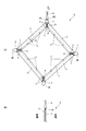
- (A) is a front view of the sound absorber of the present invention
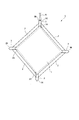
- (b) is a cross-sectional view taken along line AA in (a). It is a rear view of the sound absorber of the present invention.
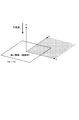
- (A)-(g) is sectional drawing which shows another sound-absorbing body. It is explanatory drawing used for the sound field calculation around a board member. It is explanatory drawing which shows the state in which the plane wave injected into the board member perpendicularly
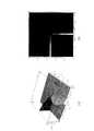
- (A) is a perspective view showing the particle velocity amplitude in the shaded region of FIG. 5, and (b) is a plan view showing the particle velocity amplitude of the shaded region in FIG. It is a perspective view which shows sound pressure distribution near the edge of a board member.
- the distribution of the sound pressure amplitude in the vicinity of the edge of the plate member is shown, (a) is a perspective view, and (b) is a plan view displayed with contour lines.
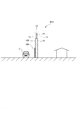
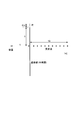
- It is explanatory drawing which shows the impedance of cloth or a thin porous sound absorption layer. It is explanatory drawing used for the sound field calculation around a cloth. It is a front view of a sound absorber. It is a graph which shows the sound absorption power with respect to a frequency. It is explanatory drawing in which the sound insulation wall was installed between the road and the residential area. It is explanatory drawing used for attenuation amount calculation of the sound insulation wall which uses a sound-absorbing body.
- the sound absorbing body S includes a square plate member 1 and a band-shaped sound absorbing material 2 extending to a side away from the end face at each of four end edges of the plate member 1.
- it is composed of four sound absorbing materials 2, but it can also be composed of one, two or three sound absorbing materials.
- the plate member 1 can be configured to be a rectangle, a circle, an ellipse, a triangle, or a polygon in addition to a square.
- the plate member 1 is configured to have a length of 0.6 m ⁇ width of 0.6 m and a thickness of 9 mm, and the sound absorbing material 2 has a high upper side of 0.7 m and a lower side of 0.56 m in FIG.
- the length (width) is a strip-shaped member having a thickness of 0.07 m, and the length R of the portion that is wrapped with the plate member 1 is 0.01 m.
- the plate member 1 is made of a material having rigidity for creating a pressure gradient by generating a sound pressure difference between the front side and the back side near the edge.
- wood is used as the material having rigidity, but any material can be used as long as it is a material having rigidity, such as composite paper obtained by superimposing various metals or a plurality of sheets of paper.
- the metal may be iron, nickel, aluminum, copper, magnesium, lead or the like, or an alloy composed of two or more of these metals. From the viewpoint of absorbing sound, a material with a surface density of 3 kg / m 2 or more is sufficient. However, if a certain effect is expected when used as a sound insulation wall, the surface density is 12 kg / m 2. Two or more materials are preferred.
- plate-like wooden auxiliary projections 3 having the same thickness as the plate member 1 extending to the side away from the corner are arranged, and in this state, the surface of the plate member 1 and the auxiliary A connecting member 4 is disposed over the surface of the protrusion 3, and the plate member 1 and the auxiliary protrusion 3 are connected and fixed via the connecting member 4 by a stopper 5 such as a push pin or a screw.
- the auxiliary protrusion 3 includes a triangular notch 3A that fits into a corner of the plate member 1 at one end in the longitudinal direction (plate member side end), and a triangle at the other end in the longitudinal direction (side end away from the plate member).
- the protrusion 3 ⁇ / b> B having a shape is provided, and a hole 3 ⁇ / b> K for passing a hanging string-like body (which may be a wire or a thread) 6 is formed in a specific auxiliary protrusion 3 of the auxiliary protrusions 3.
- the holes 3K may be formed not only on one auxiliary protrusion 3 but also on a plurality or all of the auxiliary protrusions 3. In FIGS.
- the sound absorber S is suspended by a string-like body 6 that is passed through a hole 3 ⁇ / b> K formed in one auxiliary projection 3, so that one corner of the square plate member 1 faces upward.
- the sound absorber S is suspended in the shape of a diamond, for example, a hole is formed in the two auxiliary protrusions 3 and 3, and the sound absorber S is taken from FIG. 1 using two of the string-like members passed through them. You may hang
- Each of the four sound absorbing materials 2 is attached in a stretched state between two auxiliary protrusions 3 and 3 adjacent to each other in the circumferential direction of the auxiliary protrusions 3 provided on the plate member 1. More specifically, each sound absorbing material 2 is formed in a strip shape that is long in the left-right direction and is formed in a substantially inverted trapezoidal shape when viewed from the front. In addition, a part of the lateral direction plate member side end is arranged so as to cover the edge of the plate member 1. The sound absorbing material 2 arranged in this way is fixed between the auxiliary projections 3 and 3 by a stopper 7 such as a push pin or a screw. The stopper 7 may be the same as the stopper 5 or may be different.
- the sound-absorbing material 2 for example, a woven fabric or a knitted fabric having an areal density of 0.66 kg / m 2 and a flow resistance of 924 Ns / m 3 is used.
- the nonwoven fabric may be a nonwoven fabric or an inorganic fiber such as glass wool or rock wool. It may be a porous body or a porous body made of various metal fibers.
- a sound pressure difference is generated between the front side and the back side near the edge of the plate member 1 by the plate member 1 having rigidity. That is, if the pressure on the sound source side is generated on the front side of the plate member 1, the pressure amplitude on the back side where no sound is generated on the opposite side to the sound source is smaller than the pressure amplitude on the front side. A sound pressure difference is generated between the front side and the back side near the edge of 1, and a pressure gradient can be applied between the front side and the back side near the edge.
- FIG. 5 when a plane wave having an amplitude of 1 with a velocity potential is vertically incident on a rigid plate of 1 m ⁇ 1 m, an example of calculating the distribution of the particle velocity amplitude
- FIGS. 7 is calculated and displayed, it is as shown in FIGS. This is because the sound pressure gradient becomes very large in the vicinity of the edge. If a sound absorbing material such as cloth or thin porous material is placed in such a region where the particle velocity amplitude is very large (region where the air particles vibrate extremely intensely), the air particles and the cloth or porous material It is considered that the sound energy is converted into heat energy by the friction of the fibers, and a large sound absorbing performance can be obtained. The particle velocity is proportional to the sound pressure gradient.
- the sound insulation performance can be improved with the same idea for sound insulation walls that are often used for sound insulation such as road noise and railway noise. Since the particle velocity is reduced by installing a sound absorbing material such as a cloth or a porous material in the vicinity of the edge, it is considered that there is a further sound reduction effect.
- the velocity potential of the diffraction region behind the sound insulation wall can be expressed as an integral value of the particle velocity distribution in the region above the edge (edge).
- the sound absorber S of the present invention will be described.
- the edge of the plate member 1 which is a thin rigid plate It was shown earlier that the particles vibrate very vigorously in the region near the (edge). If a sound-absorbing material such as a cloth or thin porous sound-absorbing material that does not disturb the particle velocity distribution is placed in such a region, the sound energy is converted into thermal energy by friction between the air particles and the sound-absorbing material fibers. A great sound absorption effect is expected. The frictional resistance is considered to be proportional to the particle velocity.
- FIG. 11 is an example of a sound absorber S to which such a principle is applied.
- FIG. 12 shows the result of obtaining the turbulent incident sound absorption force when the sound absorber S shown in FIG. 11 is installed in the space by simultaneously combining the equations (6) and (14). It can be seen that a relatively large sound-absorbing force is obtained even though the sound is absorbed only near the edge.
- the flow resistance r S is calculated for two types of 415 Ns / m 3 and 830 Ns / m 3 . In addition, it is also called an equivalent sound absorption area by sound absorption coefficient ⁇ area.
- the sound absorber S is composed of the plate member 1 and the sound absorbing material 2 made of cloth.
- the dimension of the plate member 1 is a square of 0.9 m ⁇ 0.9 m, and an annular cloth 2 having a width of 0.1 m is disposed on the outer peripheral edge of the plate member.
- the sound absorber S shown in FIGS. 1 (a), 1 (b) and 2 may be configured as shown in FIGS. 3 (a) to 3 (g). That is, the sound absorbing material 2 of the sound absorbing body S shown in FIGS. 1A and 1B and FIG. 2 is configured to be thinner than the plate member 1, but in FIG. The case where the thickness of the sound absorbing material 2 is the same as the thickness is shown. In FIG. 3B, the sound absorbing material 2 is configured to be thicker than the thickness of the plate member 1. The state which has protruded from the front and back to the thickness direction both sides is shown. 3C shows a case where the sound absorbing material 2 is thinner than the thickness of the plate member 1, and in FIG.
- the plate member 1 includes a tapered portion 1T that tapers toward the end face side. It has a different shape.
- the plate member 1 is configured as a curved surface that gently protrudes to the left in the drawing, and in FIG. 3 (f), the end surface 1A of the plate member 1 has a curved surface that protrudes upward. It is configured.
- the narrow part 1W which thickness is thin is provided in the end surface side of the board member 1.
- the sound insulation wall W can suppress the intrusion of the traveling sound of the vehicle C or the engine sound from the road to the house side as much as possible by absorbing the sound from the road side.
- the sound insulation wall W includes a plate member 10 having rigidity for providing a gradient by applying a sound pressure difference in the vicinity of the edge, and the front side of the upper surface of the road surface 10B of the plate member 10 and the opposite side thereof. A sound pressure difference is generated between the back side and the back side.
- a sound absorbing layer 10 ⁇ / b> A is applied to the lower surface of the road surface 10 ⁇ / b> B of the plate member 10.
- the housing-side surface (the back surface) of the sound insulation wall W may be a rigid surface or may be subjected to a sound absorption process.
- a porous sound absorbing layer as a sound absorbing material extending upward is formed on the upper end surface of the plate member 10 (a porous material made of inorganic fibers or a porous material made of various metal fibers, or a cloth). Good) 11, the front side and the back side of the sound absorbing layer 11 are protected by a protective material 12 such as a wire mesh or punching metal, and a rain-preventing cap 13 is provided on the upper end of the protective material 12 to form a sound insulating wall W Yes.
- the construction of the sound insulation wall W as described above is effective in reducing road traffic noise (which can also be used for railway noise, etc.).
- the sound pressure in the region on the diffraction side is reduced by converting the sound energy into thermal energy in the sound absorption layer 11 from the accelerated large particle velocity appearing in the region near the edge (edge) and reducing the particle velocity. It is possible to make it.
- This can be understood from an example in which the calculation of the diffracted sound field is attempted by installing a cloth at the tip of the sound insulation wall (thin semi-infinite rigid flat plate) as shown in FIG.
- the sound pressure in the diffraction side region can be obtained by integrating the particle velocity distribution on the surface extending above the sound insulation wall. Therefore, the diffraction sound can be reduced by reducing the large particle velocity in those regions, particularly in the vicinity of the edge.
- FIG. 15 shows the distribution of the particle velocity amplitude above the sound insulation wall when a spherical wave is generated from the sound source position shown in FIG.
- the horizontal axis represents the distance from the front end of the sound insulation wall. It can be seen that the particle velocity amplitude is very large above the sound insulation wall and in the vicinity of the edge. It should be noted that the sound source was calculated with the intensity at which the amplitude of the velocity potential becomes 1 at a position 1 m away.
- FIG. 16 shows the result of calculating the level attenuation (also referred to as insertion loss) by installing the sound insulation wall at the diffraction side sound receiving position shown in FIG.
- (a) shows only the sound insulation wall
- (b) shows the result when 50cm wide cloth is installed at the top of the tip
- (c) shows the result when the height of the sound insulation wall is matched with the top edge of the cloth without installing cloth. It is.
- the cloth flow resistance is 830 Ns / m 3 . From these results, it can be said that the effect of the installed cloth is greater than expected.
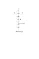
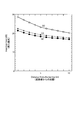
- FIG. 17 is a graph showing measured values and theoretical calculation values of the sound absorbing force per sound absorber. The measured values were measured by suspending the sound absorber S of FIGS. 1 (a), 1 (b) and 2 in the indoor space, and the theoretically calculated values and the measured values are similar. Yes. In addition, the higher the frequency, the greater the sound absorption force, which is particularly effective for higher frequencies.
- the present invention is very simple and compact, it is considered that the present invention has good performance and can be widely applied from the viewpoint of manufacturing cost and ease of construction. Moreover, the sound of a low frequency can be absorbed, so that the area of the plate member 1 which comprises the sound-absorbing body S is increased, and the area (size) of the plate member 1 can be changed according to the frequency which wants to absorb sound.
- FIG. 18 shows a graph of experimental results and calculated values of sound insulation (sound absorption) of the sound insulation wall.
- a model in which the sound insulation wall shown in FIG. 14 is made small is produced, and the experimental results and calculated values of the insertion loss at a point away from the sound insulation wall by using the model are used (using the above-described equation (14)).
- the calculated values are shown in the graph of FIG.
- As the model a wall made of a wooden plate member having a thickness of 9 mm and a length of 90 cm ⁇ width 180 cm, and a cloth (size of 5 cm length ⁇ width 180 cm) as a sound absorbing material at the upper end of the plate member. Two walls of sound insulation wall were prepared.
- FIG. 1 shows a graph of experimental results and calculated values of sound insulation (sound absorption) of the sound insulation wall.
- the insertion loss is measured using the sound insulation wall, the measured value is plotted and the broken line K1 connected by a straight line, and the plate member of the sound insulation wall is regarded as a semi-infinite barrier.
- the insertion loss was calculated according to equation (14) by regarding the straight line K10 obtained by plotting the calculated value obtained by calculating the insertion loss by the equation (14) assuming that it is an infinite barrier and connecting it with a straight line, and the plate member of the wall as a semi-infinite barrier.
- a broken line K11 plotted by plotting the calculated values and a broken line K12 connecting the straight lines by measuring the insertion loss using a wall and plotting the measured values are drawn.
- the cloth has an areal density of 0.6 kg / m 2 and a flow resistance of 789 Ns / m 3 .
- the frequency of the measured value is plotted as a value obtained by reducing the frequency measured by the model to 1/10.
- the value of the broken line K2 is higher than the value of the straight line K10. From this, the insertion loss (sound insulation effect) calculated by the equation (14) with the plate member of the sound insulation wall regarded as a semi-infinite barrier rather than the insertion loss (sound insulation effect) of the wall made the same height as the upper end of the cloth of the sound insulation wall. I understand that it is expensive. On the contrary, the value of the broken line K11 is lower than the value of the straight line K10. Therefore, the insertion loss (sound insulation effect) calculated by equation (14) with the wall regarded as a semi-infinite barrier is higher than the insertion loss (sound insulation effect) of the wall that is the same height as the top edge of the cloth of the sound insulation wall.
- the value of the broken line K1 and the value of the broken line K2 are very close values. From this, it is clear that the calculated value (value of the broken line K2) obtained by calculating the insertion loss by the equation (14) by regarding the plate member of the sound insulating wall as a semi-infinite barrier is a highly reliable value. Further, the value of the broken line K11 and the value of the broken line K12 are very close values. From this, it is clear that the calculated value (value of the broken line K11) calculated by the equation (14) by considering the wall on which the cloth is not installed as a semi-infinite barrier is a highly reliable value. A part of the sound insulation effect includes a sound absorption effect.
- the insertion loss (sound insulation effect) increases if a sound absorbing material (cloth in FIG. 18) is installed at the upper end of the plate member in the sound insulation wall.
- the value of the insertion loss obtained by calculation is highly reliable with approximately the same value as the measured value.
- FIG. 18 when a cloth having a surface density of 0.6 kg / m 2 and a flow resistance of 789 Ns / m 3 is installed at the upper end of the plate member constituting the sound insulation wall, the cloth member is not equipped with a cloth. The case where there is a sound insulation effect is shown.
- FIG. 19 shows that the surface density and the flow resistance are both the upper part of the sound absorbing material, whereas the surface density and the flow resistance are uniform from the lower part to the upper part.
- FIG. 19 It is a graph which shows the result that the sound-insulating wall using the sound-absorbing material (it is called gradation sound-absorbing material in order to distinguish from a uniform sound-absorbing material) comprised so that it may become a small value has a further sound-insulating effect.
- the graph of FIG. 19 represents the insertion loss with respect to the noise level (A characteristic sound pressure level) in the automobile, and is created based on the calculated insertion loss with high reliability as described above.
- a uniform sound-absorbing material means what is comprised so that the value of surface density and flow resistance may become the same from the bottom to the top.
- a broken line H obtained by plotting a calculated value obtained by calculating the insertion loss by regarding a plate member having the same height as the sound insulation wall having a cloth installed on the upper end of the plate member as a semi-infinite barrier
- Five broken lines G1 to G5 are drawn by plotting the calculated values of the insertion loss calculated by regarding the plate member of the sound insulating wall with the gradation sound absorbing material installed at the upper end as a semi-infinite barrier and connecting them with straight lines.
- Table 1 below shows the calculated insertion loss (dB) with respect to the distance (m) from the wall.
- the calculated value is a value calculated using the above-described equation (14).
- the uniform sound absorbing material of the polygonal line U1 has a surface density of 192 kg / m 2 and a flow resistance of 6400 Ns / m 3 .
- the uniform sound absorbing material of the broken line U2 has a surface density of 96 kg / m 2 and a flow resistance of 3200 Ns / m 3 .
- the uniform sound absorbing material of the broken line U3 has a surface density of 12 kg / m 2 and a flow resistance of 400 Ns / m 3 .
- the uniform sound absorbing material of the broken line U4 has a surface density of 48 kg / m 2 and a flow resistance of 1600 Ns / m 3 .
- the uniform sound absorbing material of the broken line U5 has a surface density of 24 kg / m 2 and a flow resistance of 800 Ns / m 3 .
- the gradation sound absorbing material of the polygonal line G1 has a surface density of 192 kg / m 2 at the lower end portion of the sound absorbing material and a flow resistance of 6400 Ns / m 3. It is comprised so that it may become a near value.
- Gradient sound absorbing material of the polygonal line G2 the surface density of the lower end portion of the sound absorbing material to flow resistance at 96 kg / m 2 was 3200Ns / m 3, the values becomes smaller toward the upper end, to zero or zero at the upper end It is comprised so that it may become a near value.
- the gradation sound absorbing material of the polygonal line G3 has a surface density of 12 kg / m 2 at the lower end portion of the sound absorbing material and a flow resistance of 400 Ns / m 3. It is comprised so that it may become a near value.
- the gradation sound absorbing material of the polygonal line G4 has a surface density of 48 kg / m 2 at the lower end portion of the sound absorbing material and a flow resistance of 1600 Ns / m 3. It is comprised so that it may become a near value.
- the broken line G5 gradation sound-absorbing material has a surface density of 24 kg / m 2 and a flow resistance of 800 Ns / m 3 at the lower end of the sound-absorbing material. It is configured to be a value.
- the values of the broken lines U1 to U5 and the broken lines G1 to G5 are higher than the value of the broken line H. From this, it can be seen that the sound insulating wall provided with a cloth as a sound absorbing material on the upper end of the plate member has a better sound insulating effect than a wall not using the sound absorbing material.
- the polygonal line G2 has the highest insertion loss (sound insulation effect).
- the insertion loss (sound insulation effect) of the remaining broken lines G1, G2, G4, G5 excluding the broken line G3 is higher than that of the broken line U5 having the highest insertion loss (sound insulation effect) among the broken lines U1 to U5. ing.
- the insertion loss (sound insulation effect) of the broken line G3 is higher than the insertion loss (sound insulation effect) of the broken line U1 having the lowest insertion loss (sound absorption effect) in the graph.
- the sound insulation wall W consumes energy of the particle velocity of the air that is installed at the upper end of the plate member 10 having rigidity for providing a pressure gradient by applying a sound pressure difference near the edge and accelerated by the pressure gradient.
- the gradation sound absorbing material 14 is composed of three types of sound absorbing materials 14A, 14B, and 14C that are thicker toward the lower side.
- three sound absorbing materials 14A, 14B and 14C having different thicknesses are arranged in the vertical direction so that the thickness of the gradation sound absorbing material 14 is thinner, and the gradation sound absorbing material 14 has a plurality of steps in the vertical direction. It has a multi-stage shape.
- the surface density and flow resistance value of the lower sound-absorbing material 14A are larger than the surface density and flow resistance value of the intermediate sound-absorbing material 14B.
- the surface density and flow resistance of the uppermost sound absorbing material 14C are smaller than the surface density and flow resistance of the sound absorbing material 14B below it.
- the gradation sound absorbing material 14 is configured in a substantially triangular shape having a linear (or curved) inclined surface so that the thickness becomes thinner toward the upper side.
- the values of the surface density and flow resistance of the gradation sound absorbing material 14 are gradually smaller toward the upper side, and are zero or close to zero at the upper end. With this configuration, the surface density and the flow resistance value of the gradation sound absorbing material 14 change linearly (continuously) along the vertical direction. The sound insulation effect can be effectively eliminated without lowering the sound insulation effect.
- the gradation sound absorbing material 14 is composed of six sound absorbing materials 14A having the same thickness and the same size, and having the same surface density and flow resistance.
- three sound absorbing materials 14A are arranged on the upper end of the plate member 10 in the thickness direction, and two sound absorbing materials 14A, 14A are arranged on the upper ends of the three sound absorbing materials 14A, 14A, 14A.
- One sound absorbing material 14A is arranged at the upper ends of the two sound absorbing materials 14A, 14A.
- the gradation sound-absorbing material 14 is configured in a plurality of steps having a plurality of steps in the vertical direction.
- the gradation sound absorbing material 14 is composed of five sound absorbing materials 14A, 14B, and 14C having the same thickness and different heights (vertical dimensions). That is, the lower second sound absorbing material 14B is disposed on both sides in the thickness direction of the tallest first sound absorbing material 14C, and the second lower sound absorbing material 14B, 14B has a lower height than the second sound absorbing material 14B. Three sound absorbing materials 14A are arranged. Also in this case, the gradation sound-absorbing material 14 is configured in a plurality of steps having a plurality of steps in the vertical direction.
- the thickness of the gradation sound absorbing material 14 is 5 from the bottom of the two third sound absorbing materials 14A, the two second sound absorbing materials 14B, and the one first sound absorbing material 14C. It becomes thin in order of three sheets, two second sound absorbing materials 14B and one first sound absorbing material 14C, and one first sound absorbing material 14C. Therefore, the surface density and the flow resistance value of the gradation sound absorbing material 14 become smaller in order from the lower side.
- the gradation sound absorbing material 14 is configured to have the same thickness in the vertical direction, but the surface density and flow resistance of the lower part 14a are the largest in the vertical direction, and the surface density of the intermediate part 14b.
- the flow resistance value is smaller than the surface density and flow resistance value of the lower portion 14a, and the surface density and flow resistance value of the upper portion 14c are the smallest.
- the gradation sound absorbing material 14 in FIG. 20 (e) is made of sponge or foam, and is formed so that the holes formed in the lower part 14a are the most dense, and the holes in the lower part 14a.
- the shape and size of the hole are determined so as to maximize the flow resistance.
- the shape and size of the hole are determined so that the holes formed in the upper part 14c are formed sparsely and the value of the flow resistance of the hole is minimized.
- the gradation sound absorbing material 14 is composed of the three sound absorbing materials 14A, 14B, and 14C, but the gradation sound absorbing material 14 may be composed of one sound absorbing material.
- 20 (a), (c), (d), and (e) show the case where the surface density and the flow resistance value of the sound absorbing material are changed in three stages in the vertical direction.
- the surface density and flow resistance values in the vertical direction can be changed in a nearly linear state.
- the surface density and flow resistance of the gradation sound absorbing material change in two stages in the vertical direction. That is, the surface density and flow resistance of the gradation sound absorbing material are smaller in the upper part than the lower part of the gradation sound absorbing material.
- the sound insulation effect is higher when both the surface density value and the flow resistance value of the gradation sound absorbing material are set so that the upper part is smaller than the lower part of the gradation sound absorbing material.
- only one of the surface density value and the flow resistance value may be set so that the upper portion is smaller than the lower portion of the gradation sound absorbing material.
- the sound absorbing material 2 is provided over almost the entire edge of the plate member 1, but it may be provided only in part. Further, although the sound absorbing material 2 is arranged so as to partially cover the edge of the plate member 1, the sound absorbing material 2 may be arranged so as not to cover the edge of the plate member 1 at all.
- the sound absorber S may be suspended and used, or may be fixed to a floor and used for a partition (partition material).
- the sound absorbing material is arranged at the upper end of the plate member, but the sound absorbing material may be arranged at the lateral end of the plate member. In short, if the sound absorbing material is disposed so as to extend outward from the edge of the plate member along the surface direction of the plate member, the mounting position of the sound absorbing material is not particularly limited.
Landscapes
- Engineering & Computer Science (AREA)
- Physics & Mathematics (AREA)
- Architecture (AREA)
- Acoustics & Sound (AREA)
- Civil Engineering (AREA)
- Structural Engineering (AREA)
- Multimedia (AREA)
- Electromagnetism (AREA)
- Devices Affording Protection Of Roads Or Walls For Sound Insulation (AREA)
- Soundproofing, Sound Blocking, And Sound Damping (AREA)
- Building Environments (AREA)
Abstract
Priority Applications (5)
| Application Number | Priority Date | Filing Date | Title |
|---|---|---|---|
| SG2013055447A SG192056A1 (en) | 2011-01-24 | 2012-01-24 | Sound barrier using sound absorber |
| KR1020137014531A KR101549045B1 (ko) | 2011-01-24 | 2012-01-24 | 흡음체를 사용한 방음벽 |
| HK15104066.4A HK1203582B (en) | 2011-01-24 | 2012-01-24 | Sound insulation wall equipped with a sound‐absorbing body |
| JP2012554807A JP5380610B2 (ja) | 2011-01-24 | 2012-01-24 | 吸音体を用いた遮音壁 |
| CN201280004648.5A CN104136695B (zh) | 2011-01-24 | 2012-01-24 | 使用吸声体的隔音墙 |
Applications Claiming Priority (2)
| Application Number | Priority Date | Filing Date | Title |
|---|---|---|---|
| JP2011-012150 | 2011-01-24 | ||
| JP2011012150 | 2011-01-24 |
Publications (1)
| Publication Number | Publication Date |
|---|---|
| WO2012102278A1 true WO2012102278A1 (fr) | 2012-08-02 |
Family
ID=46580844
Family Applications (1)
| Application Number | Title | Priority Date | Filing Date |
|---|---|---|---|
| PCT/JP2012/051471 Ceased WO2012102278A1 (fr) | 2011-01-24 | 2012-01-24 | Corps absorbant acoustique et mur d'isolation acoustique équipé dudit corps |
Country Status (6)
| Country | Link |
|---|---|
| JP (2) | JP5380610B2 (fr) |
| KR (1) | KR101549045B1 (fr) |
| CN (1) | CN104136695B (fr) |
| MY (1) | MY178957A (fr) |
| SG (1) | SG192056A1 (fr) |
| WO (1) | WO2012102278A1 (fr) |
Cited By (5)
| Publication number | Priority date | Publication date | Assignee | Title |
|---|---|---|---|---|
| JP2014185406A (ja) * | 2013-03-22 | 2014-10-02 | Nippon Sheet Glass Environment Amenity Co Ltd | 繊維マット状吸音材の製法 |
| JP2014240580A (ja) * | 2013-06-12 | 2014-12-25 | 戸田建設株式会社 | 流れ抵抗材の設置方法と取付金具、および仮設防音壁 |
| JP2014240581A (ja) * | 2013-06-12 | 2014-12-25 | 戸田建設株式会社 | 防音ユニット |
| WO2015114929A1 (fr) * | 2014-01-28 | 2015-08-06 | 日本板硝子環境アメニティ株式会社 | Panneau acoustique et équipement de paroi d'insonorisation |
| JP2015224469A (ja) * | 2014-05-28 | 2015-12-14 | 学校法人 関西大学 | エッジ効果抑制型防音壁用パネル |
Families Citing this family (4)
| Publication number | Priority date | Publication date | Assignee | Title |
|---|---|---|---|---|
| CN106854855A (zh) * | 2015-12-08 | 2017-06-16 | 北京知易普道技术有限责任公司 | 一种吸声体及使用该吸声体的声屏障 |
| CN109643536B (zh) | 2016-08-26 | 2023-05-02 | 富士胶片株式会社 | 防音结构体 |
| CN109065013A (zh) * | 2018-08-28 | 2018-12-21 | 中国空气动力研究与发展中心低速空气动力研究所 | 一种基于流阻和面密度耦合渐变的顶端优势声屏障设计方法 |
| KR102335158B1 (ko) | 2020-03-11 | 2021-12-02 | 경성대학교 산학협력단 | 열화상 카메라를 이용한 사람 객체별 체온 감지 및 추적 방법 |
Citations (4)
| Publication number | Priority date | Publication date | Assignee | Title |
|---|---|---|---|---|
| JPS5146969B2 (fr) * | 1973-07-10 | 1976-12-11 | ||
| JPH01138909U (fr) * | 1988-02-29 | 1989-09-22 | ||
| JPH09265291A (ja) * | 1996-03-28 | 1997-10-07 | Mitsubishi Electric Corp | 音波位相変化装置及び防音壁 |
| JP2002138421A (ja) * | 2000-10-27 | 2002-05-14 | Bridgestone Corp | 透光型吸音体 |
Family Cites Families (8)
| Publication number | Priority date | Publication date | Assignee | Title |
|---|---|---|---|---|
| CN2194936Y (zh) * | 1994-04-11 | 1995-04-19 | 南亚塑胶工业股份有限公司 | 改良型移动式隔音墙 |
| CN101000763A (zh) * | 2006-01-10 | 2007-07-18 | 深圳市海川实业股份有限公司 | 一种玻璃纤维复合材料吸音板 |
| US20080086957A1 (en) * | 2006-10-04 | 2008-04-17 | Averill Ronald C | Noise-attenuating laminate composite wallboard panel and methods for manufacturing same |
| JP5219448B2 (ja) * | 2007-10-17 | 2013-06-26 | 株式会社熊谷組 | 防音壁 |
| CN201236395Y (zh) * | 2008-08-05 | 2009-05-13 | 升逸豪纸业新材料(上海)有限公司 | 一种建筑墙体 |
| CN201614671U (zh) * | 2010-02-03 | 2010-10-27 | 营口春港实业有限公司 | 隔音墙 |
| CN101806109B (zh) * | 2010-03-19 | 2012-12-19 | 中国京冶工程技术有限公司 | 蒸压轻质加气混凝土组合隔音墙 |
| CN201620517U (zh) * | 2010-04-13 | 2010-11-03 | 郭文英 | 轻质隔音墙板 |
-
2012
- 2012-01-24 WO PCT/JP2012/051471 patent/WO2012102278A1/fr not_active Ceased
- 2012-01-24 CN CN201280004648.5A patent/CN104136695B/zh active Active
- 2012-01-24 MY MYPI2013002730A patent/MY178957A/en unknown
- 2012-01-24 SG SG2013055447A patent/SG192056A1/en unknown
- 2012-01-24 JP JP2012554807A patent/JP5380610B2/ja active Active
- 2012-01-24 KR KR1020137014531A patent/KR101549045B1/ko not_active Expired - Fee Related
-
2013
- 2013-09-27 JP JP2013201581A patent/JP2014029551A/ja active Pending
Patent Citations (4)
| Publication number | Priority date | Publication date | Assignee | Title |
|---|---|---|---|---|
| JPS5146969B2 (fr) * | 1973-07-10 | 1976-12-11 | ||
| JPH01138909U (fr) * | 1988-02-29 | 1989-09-22 | ||
| JPH09265291A (ja) * | 1996-03-28 | 1997-10-07 | Mitsubishi Electric Corp | 音波位相変化装置及び防音壁 |
| JP2002138421A (ja) * | 2000-10-27 | 2002-05-14 | Bridgestone Corp | 透光型吸音体 |
Cited By (8)
| Publication number | Priority date | Publication date | Assignee | Title |
|---|---|---|---|---|
| JP2014185406A (ja) * | 2013-03-22 | 2014-10-02 | Nippon Sheet Glass Environment Amenity Co Ltd | 繊維マット状吸音材の製法 |
| JP2014240580A (ja) * | 2013-06-12 | 2014-12-25 | 戸田建設株式会社 | 流れ抵抗材の設置方法と取付金具、および仮設防音壁 |
| JP2014240581A (ja) * | 2013-06-12 | 2014-12-25 | 戸田建設株式会社 | 防音ユニット |
| WO2015114929A1 (fr) * | 2014-01-28 | 2015-08-06 | 日本板硝子環境アメニティ株式会社 | Panneau acoustique et équipement de paroi d'insonorisation |
| JP5957622B2 (ja) * | 2014-01-28 | 2016-07-27 | 日本板硝子環境アメニティ株式会社 | 吸音パネル及び防音壁設備 |
| KR20160098510A (ko) | 2014-01-28 | 2016-08-18 | 니혼 이타 가라스 강교 아메니티 가부시키가이샤 | 흡음 패널 및 방음벽 설비 |
| US9915066B2 (en) | 2014-01-28 | 2018-03-13 | Nippon Sheet Glass Environment Amenity Co., Ltd. | Sound absorbing panel and soundproof wall equipment |
| JP2015224469A (ja) * | 2014-05-28 | 2015-12-14 | 学校法人 関西大学 | エッジ効果抑制型防音壁用パネル |
Also Published As
| Publication number | Publication date |
|---|---|
| JP2014029551A (ja) | 2014-02-13 |
| SG192056A1 (en) | 2013-08-30 |
| CN104136695B (zh) | 2016-04-06 |
| MY178957A (en) | 2020-10-25 |
| CN104136695A (zh) | 2014-11-05 |
| JP5380610B2 (ja) | 2014-01-08 |
| JPWO2012102278A1 (ja) | 2014-06-30 |
| KR101549045B1 (ko) | 2015-09-01 |
| HK1203582A1 (zh) | 2015-10-30 |
| KR20130142150A (ko) | 2013-12-27 |
Similar Documents
| Publication | Publication Date | Title |
|---|---|---|
| JP5380610B2 (ja) | 吸音体を用いた遮音壁 | |
| JP5957622B2 (ja) | 吸音パネル及び防音壁設備 | |
| CN104700827B (zh) | 宽频穿孔板吸声结构 | |
| JP5866172B2 (ja) | 透光性吸音パネル | |
| JP2014052539A (ja) | 吸音構造体 | |
| JP5540481B2 (ja) | 板振動吸音装置および板振動吸音方法 | |
| JP2004170665A (ja) | 吸遮音構造 | |
| KR102089503B1 (ko) | 흡음재가 없는 회절 소음 소멸형 투명 방음판용 프레임 | |
| JP5219976B2 (ja) | 騒音低減構造体 | |
| JP2005173398A (ja) | 吸音装置 | |
| HK1203582B (en) | Sound insulation wall equipped with a sound‐absorbing body | |
| JP6635836B2 (ja) | 圧力変動低減構造 | |
| CN111894160A (zh) | 一种吸声复合结构单元及具有其的吸声体阵列 | |
| KR20140005981U (ko) | 선박 덕트형 흡음 모듈 | |
| CN210597696U (zh) | 一种吸声复合结构单元及具有其的吸声体阵列 | |
| JP4303183B2 (ja) | 二重壁構造体 | |
| US11024278B1 (en) | Acoustic absorber | |
| JP2018010127A (ja) | 消音ユニットおよび消音ユニットを用いた消音構造体 | |
| JP2006256398A (ja) | 鉄道車両及び吸音材の製造方法 | |
| JP2020027268A (ja) | 吸音部材 | |
| JP2023017306A (ja) | 端部部品とそれを用いた遮音壁 | |
| JP2018155436A (ja) | 空調用放射パネル | |
| KR101437226B1 (ko) | 선접촉 구조를 갖는 타공 박막 흡음셀 | |
| JP2018071154A (ja) | ルーバー | |
| CN205479277U (zh) | 一种能防震减噪的变速器壳体 |
Legal Events
| Date | Code | Title | Description |
|---|---|---|---|
| WWE | Wipo information: entry into national phase |
Ref document number: 201280004648.5 Country of ref document: CN |
|
| 121 | Ep: the epo has been informed by wipo that ep was designated in this application |
Ref document number: 12739264 Country of ref document: EP Kind code of ref document: A1 |
|
| DPE1 | Request for preliminary examination filed after expiration of 19th month from priority date (pct application filed from 20040101) | ||
| ENP | Entry into the national phase |
Ref document number: 20137014531 Country of ref document: KR Kind code of ref document: A |
|
| ENP | Entry into the national phase |
Ref document number: 2012554807 Country of ref document: JP Kind code of ref document: A |
|
| NENP | Non-entry into the national phase |
Ref country code: DE |
|
| 122 | Ep: pct application non-entry in european phase |
Ref document number: 12739264 Country of ref document: EP Kind code of ref document: A1 |