WO2012102282A1 - 電動ポンプ装置 - Google Patents
電動ポンプ装置 Download PDFInfo
- Publication number
- WO2012102282A1 WO2012102282A1 PCT/JP2012/051485 JP2012051485W WO2012102282A1 WO 2012102282 A1 WO2012102282 A1 WO 2012102282A1 JP 2012051485 W JP2012051485 W JP 2012051485W WO 2012102282 A1 WO2012102282 A1 WO 2012102282A1
- Authority
- WO
- WIPO (PCT)
- Prior art keywords
- motor
- state
- electric pump
- hydraulic pressure
- gain
- Prior art date
- Legal status (The legal status is an assumption and is not a legal conclusion. Google has not performed a legal analysis and makes no representation as to the accuracy of the status listed.)
- Ceased
Links
Images


Classifications
-
- F—MECHANICAL ENGINEERING; LIGHTING; HEATING; WEAPONS; BLASTING
- F04—POSITIVE - DISPLACEMENT MACHINES FOR LIQUIDS; PUMPS FOR LIQUIDS OR ELASTIC FLUIDS
- F04D—NON-POSITIVE-DISPLACEMENT PUMPS
- F04D27/00—Control, e.g. regulation, of pumps, pumping installations or pumping systems specially adapted for elastic fluids
-
- F—MECHANICAL ENGINEERING; LIGHTING; HEATING; WEAPONS; BLASTING
- F16—ENGINEERING ELEMENTS AND UNITS; GENERAL MEASURES FOR PRODUCING AND MAINTAINING EFFECTIVE FUNCTIONING OF MACHINES OR INSTALLATIONS; THERMAL INSULATION IN GENERAL
- F16H—GEARING
- F16H61/00—Control functions within control units of change-speed- or reversing-gearings for conveying rotary motion ; Control of exclusively fluid gearing, friction gearing, gearings with endless flexible members or other particular types of gearing
- F16H61/0021—Generation or control of line pressure
- F16H61/0025—Supply of control fluid; Pumps therefor
- F16H61/0031—Supply of control fluid; Pumps therefor using auxiliary pumps, e.g. pump driven by a different power source than the engine
-
- G—PHYSICS
- G05—CONTROLLING; REGULATING
- G05B—CONTROL OR REGULATING SYSTEMS IN GENERAL; FUNCTIONAL ELEMENTS OF SUCH SYSTEMS; MONITORING OR TESTING ARRANGEMENTS FOR SUCH SYSTEMS OR ELEMENTS
- G05B5/00—Anti-hunting arrangements
- G05B5/01—Anti-hunting arrangements electric
-
- H—ELECTRICITY
- H02—GENERATION; CONVERSION OR DISTRIBUTION OF ELECTRIC POWER
- H02P—CONTROL OR REGULATION OF ELECTRIC MOTORS, ELECTRIC GENERATORS OR DYNAMO-ELECTRIC CONVERTERS; CONTROLLING TRANSFORMERS, REACTORS OR CHOKE COILS
- H02P6/00—Arrangements for controlling synchronous motors or other dynamo-electric motors using electronic commutation dependent on the rotor position; Electronic commutators therefor
- H02P6/08—Arrangements for controlling the speed or torque of a single motor
- H02P6/085—Arrangements for controlling the speed or torque of a single motor in a bridge configuration
-
- F—MECHANICAL ENGINEERING; LIGHTING; HEATING; WEAPONS; BLASTING
- F16—ENGINEERING ELEMENTS AND UNITS; GENERAL MEASURES FOR PRODUCING AND MAINTAINING EFFECTIVE FUNCTIONING OF MACHINES OR INSTALLATIONS; THERMAL INSULATION IN GENERAL
- F16H—GEARING
- F16H61/00—Control functions within control units of change-speed- or reversing-gearings for conveying rotary motion ; Control of exclusively fluid gearing, friction gearing, gearings with endless flexible members or other particular types of gearing
- F16H2061/0075—Control functions within control units of change-speed- or reversing-gearings for conveying rotary motion ; Control of exclusively fluid gearing, friction gearing, gearings with endless flexible members or other particular types of gearing characterised by a particular control method
- F16H2061/0078—Linear control, e.g. PID, state feedback or Kalman
Definitions
- the present invention relates to an electric pump device.
- an electric pump device which drives an oil pump by a motor to generate hydraulic pressure (see, for example, Patent Document 1).
- Such an electric pump device is mounted, for example, on a vehicle having a so-called idle stop function that automatically stops the engine at the time of temporary stop, and hydraulically operates hydraulic devices such as a transmission mechanism at idle stop when the oil pump driven by the engine stops. To supply.
- a control device provided in this kind of electric pump device supplies drive power to the motor by executing current feedback control so that the actual current value follows the current command value corresponding to the target hydraulic pressure. There is. And the hydraulic pressure generated by the oil pump is controlled through the supply of drive power to the motor.
- the present invention has been made in view of the above-described circumstances, and an object thereof is to provide an electric pump device capable of generating a necessary hydraulic pressure quickly after starting and stably supplying the hydraulic pressure. To provide.
- an oil pump for generating hydraulic pressure, a motor for driving the oil pump, and a control device for controlling the operation of the oil pump through supply of drive power to the motor are provided.
- the control device includes a control signal output unit that outputs a motor control signal, and a drive circuit that outputs drive power based on the motor control signal, and the control signal output unit is a current command value corresponding to a target hydraulic pressure.
- An electric pump device that generates the motor control signal by executing current feedback control so as to follow an actual current value supplied to the motor, the electric pump device further including a rotational state of the motor; A state determination unit that determines whether or not the necessary hydraulic pressure is supplied to the hydraulically operated device by maintaining the state; If it is determined that, the gist that a gain change unit for changing the gain of the current feedback control so lowers the responsiveness of the current feedback control.
- the gain is changed to lower the responsiveness of the current feedback control, so that the state is not stable (for example, until the oil pressure reaches the target oil pressure after start-up) It is possible to suppress the instability of the rotation of the motor in the stable state while enhancing the response of the current feedback control in the start state of As a result, the required hydraulic pressure can be generated quickly at the time of start-up, and the hydraulic pressure can be stably supplied to the hydraulically-operated device, and the generation of abnormal noise and vibration can be suppressed.
- a second aspect of the present invention is the electric pump device according to the first aspect, wherein the state determination unit determines whether or not the stable state is based on a parameter indicating a rotational state of the motor. It is a summary.
- the control device executes the current feedback control, in the stable state where the necessary hydraulic pressure is supplied to the hydraulic device by maintaining the rotational state of the motor, the parameter indicating the rotational state of the motor changes too much I will not do. Therefore, it is possible to easily determine whether or not the motor is in the stable state by, for example, determining the amount of change or the like using the parameter indicating the rotational state of the motor as described above.
- an electric pump device capable of generating a necessary hydraulic pressure quickly after being started and capable of stably supplying the hydraulic pressure.
- FIG. 2 is a schematic configuration view showing a hydraulic circuit for supplying hydraulic pressure to the transmission mechanism.
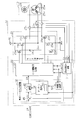
- FIG. 2 is a block diagram showing the electrical configuration of the electric pump device.
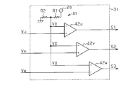
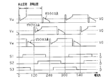
- FIG. 2 is a block diagram showing an electrical configuration of a rotational position signal generation unit. The wave form diagram of the terminal voltage of a motor coil, and a rotation position signal. The flowchart which shows the processing procedure of gain change processing.
- the electric pump device 1 shown in FIG. 1 is mounted on a vehicle (not shown) having a so-called idle stop function for automatically stopping the engine 2 when temporarily stopping.
- the electric pump device 1 is a hydraulic circuit for supplying hydraulic pressure (hydraulic oil) to a transmission mechanism 4 (in the present embodiment, a continuously variable transmission) which is a hydraulic operation device, together with a main pump 3 driven by an engine 2. It is provided in 5. Then, hydraulic pressure is supplied to the transmission mechanism 4 as an alternative to the main pump 3 when the engine 2 is stopped, such as during idling stop.
- the main pump 3 is drivingly connected to the engine 2, and by driving the engine 2, the main pump 3 sucks in hydraulic oil from the oil pan 11 and supplies hydraulic pressure to the transmission mechanism 4.
- the electric pump device 1 includes an oil pump 12 for generating oil pressure, a motor 13 for driving the oil pump 12, and an EOPECU (a control device for controlling the operation of the oil pump 12 through supply of drive power to the motor 13).
- EOP Electric Oil Pump
- ECU Electronic Control Unit (14).
- the motor pump 1 drives the oil pump 12 by the motor 13 to suck in the hydraulic oil from the oil pan 11 and supply the hydraulic pressure to the transmission mechanism 4.
- the outlet oil passage 15 of the oil pump 12 is provided with a check valve 16 for inhibiting the backflow of the hydraulic oil at the time of its stop.
- the vehicle is provided with a host ECU 18 that controls the operation of the engine 2 and the transmission mechanism 4.
- the host ECU 18 receives various sensor values such as vehicle speed and accelerator opening, and the host ECU 18 controls the operation of the engine 2 and the transmission mechanism 4 based on the input state quantities. Do. For example, the host ECU 18 stops the engine 2 when it is determined that the predetermined stop condition is satisfied based on the vehicle speed, the accelerator opening degree, etc., and restarts the engine 2 when it is determined that the predetermined restart condition is satisfied. Execute idle stop control.
- the EOPECU 14 is connected to the host ECU 18 and drives the motor 13 at idle stop based on a control signal (including a current command value I * described later) from the host ECU 18 to shift the oil pressure from the oil pump 12 It is configured to supply hydraulic pressure to the
- the EOPECU 14 controls the drive circuit 21 that supplies three-phase (U, V, W) drive power to the motor 13 and the control that outputs the motor control signal to the drive circuit 21 to drive the motor 13.
- the microcomputer 22 is provided as a signal output unit.
- a sensorless type brushless motor is adopted as the motor 13.
- the EOP ECU 14 operates the motor 13 by 120-degree square wave energization which switches the energized phase and the energization direction every 120 degrees (electrical angle). Supply drive power to
- the drive circuit 21 is formed by connecting a plurality of FETs (field effect transistors) 23a to 23f as switching elements. Specifically, the drive circuit 21 is formed by connecting in series a series circuit of each set of FETs 23a and 23d, FETs 23b and 23e, and FETs 23c and 23f, and connects each of the FETs 23a and 23d, FETs 23b and 23e, and FETs 23c and 23f.
- the points 24u, 24v, 24w are connected to the motor coils 25u, 25v, 25w of the respective phases of the motor 13, respectively.
- the drive circuit 21 employs a known PWM inverter in which three switching arms corresponding to each phase are connected in parallel with the pair of switching elements connected in series as a basic unit (switching arm). There is.
- the motor control signal output from the microcomputer 22 is a gate on / off signal that defines the switching state of each of the FETs 23a to 23f that constitute the drive circuit 21.
- the FETs 23a to 23f are turned on / off in response to motor control signals applied to the respective gate terminals, and the conduction phase and the conduction direction (conduction pattern) to the motor coils 25u, 25v, 25w of each phase are switched.
- the DC voltage of the on-vehicle power supply (battery) 26 is converted into three-phase drive power and is output to the motor 13.
- EOPECU 14 in addition to the above-described host ECU 18, voltage sensors 27u, 27v, 27w for detecting terminal voltages Vu, Vv, Vw of motor coils 25u, 25v, 25w, and an actual current value I supplied to motor 13 A current sensor 28 is connected to detect the current.
- the microcomputer 22 estimates the rotational position of the rotor 29 based on the terminal voltages Vu, Vv, Vw, and determines the energization pattern. Further, the microcomputer 22 executes current feedback control for causing the actual current value I to follow the current command value I * corresponding to the target hydraulic pressure output from the host ECU 18 at a ratio of the on time of each of the FETs 23a to 23f. Determine a certain duty ratio.
- the host ECU 18 calculates the current command value I * based on the hydraulic pressure generated by the electric pump device 1 (oil pump 12), the engine speed, and the like. Then, the microcomputer 22 outputs a motor control signal having the determined energization pattern and duty ratio, thereby supplying three-phase drive power to the motor 13, and hydraulic pressure generated by the oil pump 12 through the supply of this drive power. Control.
- the microcomputer 22 generates a rotational position signal S1 to S3 indicating the rotational position of the rotor 29 based on the terminal voltages Vu, Vv and Vw, the current command value I * and the actual value And a current feedback control unit 32 that generates a duty command value D * indicating a duty ratio based on the current value I. Further, the microcomputer 22 includes a motor control signal generation unit 33 which generates a motor control signal based on the rotational position signals S1 to S3 and the duty command value D *.
- the rotational position signal generation unit 31 includes a voltage dividing circuit 41 formed by connecting in series two resistors R1 and R2 having the same resistance value, and a reference voltage V0 output from the voltage dividing circuit 41.
- three comparators 42u, 42v, 42w that respectively compare the voltage 1/2 of the on-vehicle power supply 26 with the terminal voltages Vu, Vv, Vw are provided.
- the comparators 42u, 42v, 42w output rotational position signals S1 to S3 to the motor control signal generator 33 based on the comparison between the terminal voltages Vu, Vv, Vw and the reference voltage V0.
- the comparators 42u, 42v, 42w output “1 (high level)” as the rotational position signals S1 to S3.
- “0 (low level)” is output as the rotational position signals S1 to S3.
- the terminal voltages Vu, Vv, Vw differ in phase by 120 degrees, and the power supply voltage is detected in the 120 ° conduction section of the 180 ° electrical angle,
- the induced voltage (counter electromotive force) generated in each of the motor coils 25 u, 25 v, 25 w is detected in the 60 ° rest zone where the energization is stopped.
- the FETs 23a to 23f are switched from on to off, noise is generated due to parasitic diodes (not shown) of the FETs 23a to 23f.
- the rotational position signals S1 to S3 change at the time when the terminal voltages Vu, Vv and Vw become the reference voltage V0 (zero cross point), and the noise is eliminated to reduce the noise according to the rotational position of the rotor 29 (101 It changes regularly in the following order:) ⁇ (100) ⁇ (110) ⁇ (010) ⁇ (011) ⁇ (001).
- the current feedback control unit 32 receives the current command value I * and the actual current value I and calculates a current deviation ⁇ I, and a duty command value D based on the current deviation ⁇ I.
- a feedback operation unit (F / B operation unit) 46 for operating * is provided.
- the feedback calculation unit 46 calculates the duty command value D * by multiplying the input current deviation ⁇ I by a predetermined gain (PI gain) K. The larger the value of duty command value D *, the higher the duty ratio. Then, the current feedback control unit 32 outputs the duty command value D * thus calculated to the motor control signal generation unit 33.
- Motor control signal generation unit 33 generates a conduction pattern corresponding to rotation position signals S1 to S3 input from rotation position signal generation unit 31, and a duty ratio indicated by duty command value D * input from current feedback control unit 32. Generating a motor control signal. Further, the motor control signal generation unit 33 measures the time interval between the zero cross points, that is, the time interval in which the rotor 29 rotates 60 electrical degrees and the signal pattern indicated by the rotational position signals S1 to S3 changes. Then, the generated motor control signal is output to each of the FETs 23a to 23f of the drive circuit 21 so that the energization pattern is switched when a predetermined switching time corresponding to the time interval has elapsed from the latest zero crossing point. As a result, three-phase drive power is supplied to the motor 13. In the present embodiment, the predetermined switching time is 1/2 of the time interval between the nearest zero crossing points.
- the EOP ECU 14 passes the activated state until the hydraulic pressure generated by the oil pump 12 reaches the target hydraulic pressure after the motor 13 is activated, and maintains the rotational state of the motor 13 to shift the necessary hydraulic pressure to the transmission mechanism. It is determined whether it is in the stable state supplied to 4. Then, in the stable state, the gain K of the current feedback control is made lower than that in the starting state.
- the current feedback control unit 32 of the microcomputer 22 includes a PI gain setting unit 51 that changes the gain K, and an angular velocity calculation unit that calculates the motor angular velocity (rotor angular velocity) ⁇ based on the rotational position signals S1 to S3. 52 are provided.
- the actual current value I detected by the current sensor 28 and the motor angular velocity ⁇ calculated by the angular velocity calculation unit 52 are input to the PI gain setting unit 51.
- the PI gain setting unit 51 sets the gain K to a high response gain K1 having high responsiveness of feedback control.
- PI gain setting unit 51 determines whether or not the motor is in the stable state based on motor angular velocity ⁇ indicating the rotational state of motor 13 and actual current value I, and in the case of the stable state, gain K is set high. The response is changed to a low response gain K2 smaller than the response gain K1. That is, in the present embodiment, the PI gain setting unit 51 functions as a state determination unit and a gain change unit.
- the PI gain setting unit 51 detects the motor angular velocity ⁇ and the actual current value I at a predetermined sampling cycle, and the memory 53 provided in the PI gain setting unit 51 actually detects one cycle earlier.
- the current value I and the motor angular velocity ⁇ are stored.
- PI gain setting unit 51 calculates variation amounts X and Y from the previous values (actual current value I and motor angular velocity ⁇ one cycle before) of actual current value I and motor angular velocity ⁇ , respectively, and these variation amounts It is determined whether or not X and Y are equal to or less than a predetermined ratio Xth and Yth of each previous value as a threshold.
- the predetermined proportions Xth and Yth are set to about 10% of the previous values. Then, the PI gain setting unit 51 determines that the state is stable when the change amounts X and Y are less than or equal to the predetermined ratios Xth and Yth of the previous values continuously for a predetermined determination time, and the gain K is highly responsive. The gain K1 is changed to the low response gain K2. The angular velocity calculation unit 52 calculates the motor angular velocity ⁇ based on the time interval between the zero cross points.
- step 101 determines whether the start flag indicating the start state is set or not (step 101). If the flag is set (step 101: YES), the value of the gain K is set to the high response gain K1 (step 102). In the initial state, the start flag is set. Subsequently, the actual current value I and the motor angular velocity ⁇ are obtained (step 103), and the actual current value I and the motor angular velocity ⁇ are stored in the memory 53 (step 104).
- step 106 the previous values of the actual current value I and the motor angular velocity ⁇ are read out from the memory 53, and the change amounts X, Y and the predetermined rates Xth, Yth are calculated. It is determined whether it is the following or not (step 106).
- step 106: NO When the change amount X is larger than the predetermined ratio Xth, or when the change amount Y is larger than the predetermined ratio Yth (step 106: NO), the microcomputer 22 continuously changes the change amounts X and Y by the predetermined ratio Xth and Yth, respectively. The continuation flag indicating that it is the following is cleared (step 107). On the other hand, if the change amounts X and Y are less than or equal to the predetermined ratios Xth and Yth, respectively (step 106: YES), it is determined whether the continuation flag is set (step 108).
- step 108 NO
- the continuation flag is set (step 109)
- step 111: YES the microcomputer 22 determines that it is in the stable state, clears the start flag (step 113), and reduces the value of the gain K to a low response gain. It is set to K2 (step 114).
- step 111: NO the processing of step 113 and step 114 is not executed. If the activation flag is not set (step 101: NO), the processes of steps 102 to 114 are not executed.
- the microcomputer 22 determines whether the necessary hydraulic pressure is supplied to the transmission mechanism 4 by maintaining the rotational state of the motor 13 or not, and the gain of the current feedback control when it is in the stable state.
- the PI gain setting unit 51 is provided to change K to a low response gain K2 smaller than the high response gain K1 set in the start state.
- the gain K is changed to the low response gain K2 when determined to be in the stable state, so that the motor 13 rotates in the stable state while the same gain K is set to the high response gain K1 in the start state. Can be suppressed from becoming unstable.
- the required hydraulic pressure can be generated quickly at the time of start-up, and the hydraulic pressure can be stably supplied to the transmission mechanism 4, and the generation of abnormal noise and vibration can be suppressed.
- the electric pump device 1 of the present embodiment supplies hydraulic pressure at the time of idle stop when the vehicle is stopped, and the start and stop thereof are repeated. That is, since the operating state of the electric pump device 1 (motor 13) changes frequently, the gain K is changed as described above to improve the response in the start state and stabilize the rotation of the motor 13 in the stable state. The effect is great.
- the PI gain setting unit 51 determines that the state is stable when the change amounts X and Y of the actual current value I and the motor angular velocity ⁇ are respectively less than or equal to predetermined ratios Xth and Yth for a predetermined determination time. I did it.
- the microcomputer 22 executes the current feedback control, in the stable state, the actual current value I and the motor angular velocity ⁇ do not change much. Therefore, as in the above configuration, by using the actual current value I and the motor angular velocity ⁇ , it is possible to easily determine whether or not the stable state is accurately.
- the motor 13 is constituted by a sensorless type brushless motor. Then, the EOPECU 14 estimates the rotational position of the rotor 29 based on the induced voltages generated in the motor coils 25 u, 25 v, 25 w, and supplies the motor 13 with three-phase drive power. According to the above configuration, since the rotation sensor such as the Hall element or the like whose performance largely changes depending on the temperature is not used, the operation of the motor 13 is accurately controlled even if the electric pump device 1 is disposed in a high temperature environment such as an engine chamber can do.
- the energization pattern is switched when a predetermined switching time according to the time interval between the latest zero cross points has elapsed from the latest detected zero cross point. Therefore, the response is high, and when the motor angular velocity ⁇ fluctuates rapidly, the switching timing of the energization pattern may be largely deviated from the appropriate timing corresponding to the actual rotational position of the rotor 29, and a step out easily occurs. Become. Therefore, in the configuration in which a sensorless type brushless motor is adopted as the drive source of the oil pump 12 as in the present embodiment, the gain K is changed to the low response gain K2 in the stable state, so that the motor 13 in the stable state is The effect of stabilizing the rotation is great.
- whether or not the stable state is determined using the actual current value I and the motor angular velocity ⁇ is not limited to this, for example, only one of the actual current value I and the motor angular velocity ⁇ It may be determined whether or not it is in the stable state using.
- other parameters such as, for example, angular acceleration of the motor 13 may be used as parameters indicating the rotational state of the motor 13.
- the present invention is not limited to this.
- the hydraulic pressure generated by the oil pump 12 is detected by the hydraulic pressure sensor. It may be determined based on the detected hydraulic pressure whether or not it is in a stable state. For example, when the amount of change in hydraulic pressure to be detected continues for a predetermined determination time and is less than or equal to the threshold value, it can be determined that the state is stable.
- a sensorless type brushless motor is employed as the motor 13.
- the present invention is not limited thereto.
- a brushless motor having a rotation sensor such as a Hall element for detecting the rotational position of the rotor 29 or a DC motor with a brush Etc. may be adopted.
- the present invention is embodied in an electric pump device mounted on a vehicle having an idle stop function and supplying hydraulic pressure to the transmission mechanism.
- the present invention is not limited to this, and may be embodied in, for example, an electric pump device for electronic hydraulic power steering (EHPS) and an electric pump used for other applications.
- EHPS electronic hydraulic power steering
- the state determination unit is in the stable state when the change amounts of the actual current value and the motor angular velocity are each less than or equal to a threshold for a predetermined determination time.
- the motor is a sensorless type brushless motor
- the control device is a motor
- An electric pump device characterized in that drive power is supplied to the motor by estimating a rotational position of a rotor based on an induced voltage generated in a coil.
- the rotational position of the rotor is estimated by detecting a point (zero cross point) at which the induced voltage of each motor coil becomes the reference potential. Then, when a predetermined switching time according to a time interval (motor angular velocity) between past zero cross points elapses from the detected zero cross point, the conduction phase and the conduction direction are switched to supply three-phase drive power. Therefore, the response is high, and when the motor angular velocity fluctuates rapidly, the switching timing of the energization pattern may be largely deviated from the appropriate timing corresponding to the actual rotational position of the rotor, and the step-out easily occurs. Therefore, the effect of stabilizing the rotation of the motor in the stable state by applying the first aspect is significant.
- the oil pump supplies hydraulic oil to the hydraulically operated device.
- a main pump driven by an engine in a hydraulic circuit for driving the oil pump, wherein the control device operates the oil pump to complement the hydraulic supply to the hydraulic operating device at idle stop.
- Electric pump device According to the above configuration, the hydraulic pressure is supplied at the time of idle stop when the vehicle is stopped, and the start and stop of the electric pump device are repeated. That is, since the operating state of the electric pump device (of the motor) changes frequently, the first aspect is applied to improve the response in the start state and stabilize the rotation of the motor in the stable state. It is large.
Landscapes
- Engineering & Computer Science (AREA)
- General Engineering & Computer Science (AREA)
- Mechanical Engineering (AREA)
- Power Engineering (AREA)
- Physics & Mathematics (AREA)
- Automation & Control Theory (AREA)
- General Physics & Mathematics (AREA)
- Power Steering Mechanism (AREA)
- Control Of Transmission Device (AREA)
- Control Of Positive-Displacement Pumps (AREA)
- Control Of Electric Motors In General (AREA)
- Steering Control In Accordance With Driving Conditions (AREA)
- Control Of Motors That Do Not Use Commutators (AREA)
Abstract
本発明の一つの態様による電動ポンプ装置は、状態判定部と、ゲイン変更部とを備える。状態判定部は、モータの回転状態を維持することにより必要な油圧が油圧作動機器に供給される安定状態であるか否かを判定する。ゲイン偏光部は、状態判定部により安定状態であると判定された場合に、電流フィードバック制御の応答性を下げるべく該電流フィードバック制御のゲインを変更する。
Description
本発明は、電動ポンプ装置に関する。
従来、モータによりオイルポンプを駆動して油圧を発生させる電動ポンプ装置がある(例えば、特許文献1参照)。こうした電動ポンプ装置は、例えば一時停車時にエンジンを自動停止する所謂アイドルストップ機能を備えた車両に搭載され、エンジンにより駆動されるオイルポンプが停止するアイドルストップ時に、変速機構等の油圧作動機器に油圧を供給するようになっている。
一般に、この種の電動ポンプ装置に設けられる制御装置は、目標油圧に対応する電流指令値に実電流値を追従させるべく電流フィードバック制御を実行することにより、モータに対して駆動電力を供給している。そして、このモータへの駆動電力の供給を通じてオイルポンプで発生する油圧を制御している。
ところで、電動ポンプ装置が起動してからオイルポンプで発生する油圧が目標油圧に達するまでの間は、速やかに必要な油圧を発生させるために素早くモータの回転数(モータ角速度)を上昇させることが望ましい。そこで、電流フィードバック制御の応答性が高くなるようにそのゲインを設定することが考えられる。
一方、例えば上記のようにアイドルストップ時に油圧を供給する電動ポンプ装置では、その作動時に車両が停止しているため、外乱が小さく、また目標油圧もほとんど変化しない。そのため、目標油圧に達した後は、モータの回転状態を維持することにより油圧作動機器に必要な油圧が供給される状態(安定状態)となる。このような安定状態では、電流フィードバック制御の高い応答性は必要とされないばかりか、応答性が高いと、例えばノイズ等に対して過敏に反応することにより、かえってモータの回転を不安定にしてしまう虞がある。
このように、起動時に必要な油圧を速やかに発生させるために電流フィードバック制御の応答性を高くした場合、これに背反して、安定状態でモータの回転が不安定になり易く、ひいてはオイルポンプから供給される油圧変動につながり、異音や振動が発生する虞があった。なお、このような問題は、アイドルストップ時に油圧を供給する電動ポンプ装置に限らず、他の用途に用いられる電動ポンプ装置でも同様に生じ得る。
本発明は、上記の事情に鑑みてなされたものであって、その目的は、起動してから素早く必要な油圧を発生させることができるとともに、安定して油圧を供給することのできる電動ポンプ装置を提供することにある。
本発明の第一の態様は、油圧を発生させるオイルポンプと、前記オイルポンプを駆動するモータと、前記モータへの駆動電力の供給を通じて前記オイルポンプの作動を制御する制御装置とを備え、前記制御装置は、モータ制御信号を出力する制御信号出力部と、前記モータ制御信号に基づいて駆動電力を出力する駆動回路とを有し、前記制御信号出力部は、目標油圧に対応する電流指令値に前記モータに供給される実電流値を追従させるべく電流フィードバック制御を実行することにより前記モータ制御信号を生成する電動ポンプ装置であって、当該電動ポンプ装置が、更に、前記モータの回転状態を維持することにより必要な油圧が油圧作動機器に供給される安定状態であるか否かを判定する状態判定部と、前記状態判定部により安定状態であると判定された場合に、前記電流フィードバック制御の応答性を下げるべく該電流フィードバック制御のゲインを変更するゲイン変更部とを備えたことを要旨とする。
上記構成によれば、安定状態であると判定されると、電流フィードバック制御の応答性を下がるようにゲインが変更されるため、安定状態でない状態(例えば起動してから油圧が目標油圧に達するまでの起動状態)で電流フィードバック制御の応答性を高くしつつ、安定状態でモータの回転が不安定になることを抑制できる。これにより、起動時に素早く必要な油圧を発生させることができるとともに、油圧作動機器に安定して油圧を供給することができ、異音や振動が発生することを抑制できる。
本発明の第二の態様は、上記第一の態様の電動ポンプ装置において、前記状態判定部は、前記モータの回転状態を示すパラメータに基づいて前記安定状態であるか否かを判定することを要旨とする。
すなわち、制御装置は、電流フィードバック制御を実行しているため、モータの回転状態を維持することにより油圧作動機器に必要な油圧が供給される安定状態では、モータの回転状態を示すパラメータがあまり変化しなくなる。従って、上記構成のようにモータの回転状態を示すパラメータを用い、例えばその変化量等を判定することで、容易に安定状態であるか否かを判定することができる。
本発明によれば、起動してから素早く必要な油圧を発生させることができるとともに、安定して油圧を供給することのできる電動ポンプ装置を提供することができる。
以下、本発明を具体化した一実施形態を図面に従って説明する。
図1に示す電動ポンプ装置1は、一時停車時にエンジン2を自動停止する所謂アイドルストップ機能を備えた車両(図示略)に搭載されている。この電動ポンプ装置1は、エンジン2により駆動されるメインポンプ3とともに、油圧作動機器である変速機構4(本実施形態では、無段変速機)に油圧(作動油)を供給するための油圧回路5に設けられている。そして、アイドリングストップ時等、エンジン2の停止時におけるメインポンプ3の代替として、変速機構4への油圧の供給を実行する。
図1に示す電動ポンプ装置1は、一時停車時にエンジン2を自動停止する所謂アイドルストップ機能を備えた車両(図示略)に搭載されている。この電動ポンプ装置1は、エンジン2により駆動されるメインポンプ3とともに、油圧作動機器である変速機構4(本実施形態では、無段変速機)に油圧(作動油)を供給するための油圧回路5に設けられている。そして、アイドリングストップ時等、エンジン2の停止時におけるメインポンプ3の代替として、変速機構4への油圧の供給を実行する。
詳述すると、メインポンプ3は、エンジン2に駆動連結されており、同エンジン2の駆動により、オイルパン11から作動油を吸入して変速機構4に油圧を供給する。一方、電動ポンプ装置1は、油圧を発生させるオイルポンプ12と、オイルポンプ12を駆動するモータ13と、モータ13への駆動電力の供給を通じてオイルポンプ12の作動を制御する制御装置としてのEOPECU(EOP:Electric Oil Pump、 ECU:Electronic Control Unit)14とを備えている。そして、電動ポンプ装置1は、モータ13によってオイルポンプ12が駆動されることにより、オイルパン11から作動油を吸入して変速機構4に油圧を供給する。なお、オイルポンプ12の出口油路15には、その停止時における作動油の逆流を禁止する逆止弁16が設けられている。
車両には、エンジン2及び変速機構4の作動を制御する上位ECU18が設けられている。上位ECU18には、車速やアクセル開度等の各種センサ値が入力されるようになっており、上位ECU18は、入力されるこれら各状態量に基づいてこれらエンジン2及び変速機構4の作動を制御する。例えば、上位ECU18は、上記車速やアクセル開度等に基づいて所定の停止条件が成立したと判定するとエンジン2を停止させるとともに、所定の再始動条件が成立したと判定するとエンジン2を再始動させるアイドルストップ制御を実行する。
また、EOPECU14は、上位ECU18に接続されており、同上位ECU18からの制御信号(後述する電流指令値I*を含む)に基づき、アイドルストップ時にモータ13を駆動してオイルポンプ12から変速機構4に油圧を供給する構成となっている。
次に、電動ポンプ装置の電気的構成について説明する。
図2に示すように、EOPECU14は、モータ13に三相(U,V,W)の駆動電力を供給する駆動回路21と、駆動回路21にモータ制御信号を出力してモータ13を駆動する制御信号出力部としてのマイコン22とを備えている。なお、本実施形態では、モータ13には、センサレスタイプのブラシレスモータが採用されており、EOPECU14は、120度(電気角)毎に通電相及び通電方向を切り替える120度矩形波通電により、モータ13に駆動電力を供給する。
図2に示すように、EOPECU14は、モータ13に三相(U,V,W)の駆動電力を供給する駆動回路21と、駆動回路21にモータ制御信号を出力してモータ13を駆動する制御信号出力部としてのマイコン22とを備えている。なお、本実施形態では、モータ13には、センサレスタイプのブラシレスモータが採用されており、EOPECU14は、120度(電気角)毎に通電相及び通電方向を切り替える120度矩形波通電により、モータ13に駆動電力を供給する。
駆動回路21は、スイッチング素子としての複数のFET(電界効果型トランジスタ)23a~23fを接続してなる。具体的には、駆動回路21は、FET23a,23d、FET23b,23e、及びFET23c,23fの各組の直列回路を並列に接続してなり、FET23a,23d、FET23b,23e、FET23c,23fの各接続点24u,24v,24wはそれぞれモータ13の各相のモータコイル25u,25v,25wに接続されている。
つまり、駆動回路21には、直列に接続された一対のスイッチング素子を基本単位(スイッチングアーム)として、各相に対応する3つのスイッチングアームを並列に接続してなる周知のPWMインバータが採用されている。また、マイコン22の出力するモータ制御信号は、駆動回路21を構成する各FET23a~23fのスイッチング状態を規定するゲートオン/オフ信号となっている。そして、それぞれのゲート端子に印加されるモータ制御信号に応答して各FET23a~23fがオン/オフし、各相のモータコイル25u,25v,25wへの通電相及び通電方向(通電パターン)が切り替わることにより、車載電源(バッテリ)26の直流電圧が三相の駆動電力に変換され、モータ13へと出力される。
EOPECU14には、上記した上位ECU18に加え、モータコイル25u,25v,25wの端子電圧Vu,Vv,Vwを検出するための電圧センサ27u,27v,27w、及びモータ13に通電される実電流値Iを検出するための電流センサ28が接続されている。
マイコン22は、各端子電圧Vu,Vv,Vwに基づいてロータ29の回転位置を推定し、通電パターンを決定する。また、マイコン22は、上位ECU18から出力される目標油圧に対応した電流指令値I*に実電流値Iを追従させるための電流フィードバック制御を実行することにより各FET23a~23fのオン時間の割合であるデューティ比を決定する。なお、上位ECU18は、電動ポンプ装置1(オイルポンプ12)で発生する油圧やエンジン回転数等に基づいて電流指令値I*を演算する。そして、マイコン22は、決定された通電パターン及びデューティ比を有するモータ制御信号を出力することにより、モータ13に三相の駆動電力を供給し、この駆動電力の供給を通じてオイルポンプ12で発生する油圧を制御する。
詳述すると、マイコン22は、各端子電圧Vu,Vv,Vwに基づいてロータ29の回転位置を示す回転位置信号S1~S3を生成する回転位置信号生成部31と、電流指令値I*及び実電流値Iに基づいてデューティ比を示すデューティ指令値D*を生成する電流フィードバック制御部32とを備えている。また、マイコン22は、これら回転位置信号S1~S3及びデューティ指令値D*に基づいてモータ制御信号を生成するモータ制御信号生成部33を備えている。
図3に示すように、回転位置信号生成部31は、抵抗値の等しい2つの抵抗R1,R2を直列接続してなる分圧回路41と、分圧回路41から出力される基準電圧V0(本実施形態では、車載電源26の1/2の電圧)と端子電圧Vu,Vv,Vwとをそれぞれ比較する3つのコンパレータ42u,42v,42wとを備えている。各コンパレータ42u,42v,42wは、端子電圧Vu,Vv,Vwと基準電圧V0との比較に基づいて回転位置信号S1~S3をモータ制御信号生成部33に出力する。具体的には、各コンパレータ42u,42v,42wは、端子電圧Vu,Vv,Vwが基準電圧V0よりも大きい場合には、回転位置信号S1~S3として「1(ハイレベル)」を出力し、端子電圧Vu,Vv,Vwが基準電圧V0以下である場合には、回転位置信号S1~S3として「0(ローレベル)」を出力する。
ここで、図4に示すように、端子電圧Vu,Vv,Vwは、位相が120度ずつ異なっており、電気角180度のうち、通電された120度の通電区間では電源電圧が検出され、通電が休止された60度の休止区間では各モータコイル25u,25v,25wに生じた誘起電圧(逆起電力)が検出される。なお、各FET23a~23fがオンからオフに切り替わる時には、同FET23a~23fの寄生ダイオード(図示略)に起因したノイズが生じる。そして、回転位置信号S1~S3は、端子電圧Vu,Vv,Vwが基準電圧V0となる時点(ゼロクロス点)で変化し、上記ノイズを除去することにより、ロータ29の回転位置に応じて(101)→(100)→(110)→(010)→(011)→(001)の順序で規則的に変化する。
図2に示すように、電流フィードバック制御部32は、電流指令値I*及び実電流値Iが入力されて電流偏差ΔIを演算する減算器45と、この電流偏差ΔIに基づいてデューティ指令値D*を演算するフィードバック演算部(F/B演算部)46とを備えている。フィードバック演算部46は、入力された電流偏差ΔIに所定のゲイン(PIゲイン)Kを乗ずることにより、デューティ指令値D*を演算する。なお、デューティ指令値D*の値が大きいほど、デューティ比は高くなる。そして、電流フィードバック制御部32は、このように演算されたデューティ指令値D*をモータ制御信号生成部33に出力する。
モータ制御信号生成部33は、回転位置信号生成部31から入力される回転位置信号S1~S3に対応する通電パターン、及び電流フィードバック制御部32から入力されるデューティ指令値D*に示されるデューティ比を有するモータ制御信号を生成する。また、モータ制御信号生成部33は、ゼロクロス点間の時間間隔、すなわちロータ29が電気角で60度回転して回転位置信号S1~S3の示す信号パターンが変化する時間間隔を計測している。そして、最新のゼロクロス点から上記時間間隔に応じた所定の切り替え時間が経過した時点で通電パターンが切り替わるように、生成したモータ制御信号を駆動回路21の各FET23a~23fに出力する。これにより、モータ13に三相の駆動電力が供給される構成となっている。なお、本実施形態では、所定の切り替え時間は、直近のゼロクロス点間の時間間隔の1/2の時間である。
(ゲイン変更処理)
次に、本実施形態のマイコンによる電流フィードバック制御のゲインを電動ポンプ装置の作動状態に応じて変更するゲイン変更処理について説明する。
次に、本実施形態のマイコンによる電流フィードバック制御のゲインを電動ポンプ装置の作動状態に応じて変更するゲイン変更処理について説明する。
上述のように、起動時に必要な油圧を変速機構4に速やかに供給するために、電流フィードバック制御の応答性が高くなるようにそのゲインKを高く設定することが考えられる。しかし、電動ポンプ装置1は、車両が停止しているアイドルストップ時に油圧を供給するものであることから外乱が小さく、また目標油圧もほとんど変化しない。そのため、目標油圧に達した後は、モータ13の回転状態を維持することにより必要な油圧が供給される安定状態となる。そして、このような安定状態で電流フィードバック制御の応答性が高いと、モータ13の回転を不安定にしてしまう虞がある。
この点を踏まえ、EOPECU14は、モータ13が起動してからオイルポンプ12で発生する油圧が目標油圧に達するまでの起動状態をすぎ、モータ13の回転状態を維持することにより必要な油圧が変速機構4に供給される安定状態であるか否かを判定する。そして、安定状態である場合には、起動状態に比べ、電流フィードバック制御のゲインKを低くするようにしている。
詳述すると、マイコン22の電流フィードバック制御部32には、ゲインKを変更するPIゲイン設定部51と、回転位置信号S1~S3に基づいてモータ角速度(ロータの角速度)ωを演算する角速度演算部52が設けられている。PIゲイン設定部51には、上記電流センサ28により検出される実電流値I及び角速度演算部52により演算されるモータ角速度ωが入力される。このPIゲイン設定部51は、モータ13の起動時には、ゲインKをフィードバック制御の応答性が高い高応答ゲインK1に設定する。そして、PIゲイン設定部51は、これらモータ13の回転状態を示すモータ角速度ω及び実電流値Iに基づいて安定状態であるか否かを判定し、安定状態である場合に、ゲインKを高応答ゲインK1よりも小さな低応答ゲインK2に変更する。すなわち、本実施形態では、PIゲイン設定部51が状態判定部及びゲイン変更部として機能する。
さらに詳述すると、PIゲイン設定部51は、所定のサンプリング周期で上記モータ角速度ω及び実電流値Iを検出しており、同PIゲイン設定部51に設けられたメモリ53に一周期前の実電流値I及びモータ角速度ωを記憶している。また、PIゲイン設定部51は、実電流値I及びモータ角速度ωのそれぞれの前回値(一周期前の実電流値I及びモータ角速度ω)からの変化量X,Yを演算し、これら変化量X,Yが閾値としての各前回値の所定割合Xth,Yth以下であるか否かを判定する。なお、本実施形態では、所定割合Xth,Ythは各前回値の10%程度の値に設定されている。そして、PIゲイン設定部51は、所定の判定時間継続して変化量X,Yが各前回値の所定割合Xth,Yth以下である場合に、安定状態であると判定し、ゲインKを高応答ゲインK1から低応答ゲインK2に変更する。なお、角速度演算部52は、ゼロクロス点間の時間間隔に基づいてモータ角速度ωを演算する。
次に、本実施形態のマイコン(PIゲイン設定部)による電流フィードバック制御のゲイン変更の処理手順を図5のフローチャートに従って説明する。
上位ECU18からオイルポンプ12で油圧を発生させる旨の制御信号が入力されると、マイコン22は、起動状態であることを示す起動フラグがセットされているか否かを判定し(ステップ101)、起動フラグがセットされている場合には(ステップ101:YES)、ゲインKの値を高応答ゲインK1に設定する(ステップ102)。なお、初期状態では、起動フラグがセットされるようになっている。続いて、実電流値I及びモータ角速度ωを取得して(ステップ103)、当該実電流値I及びモータ角速度ωをメモリ53に記憶する(ステップ104)。そして、実電流値I及びモータ角速度ωの前回値をメモリ53から読み出して変化量X,Y及び所定割合Xth,Ythを演算し(ステップ105)、変化量X,Yがそれぞれ所定割合Xth,Yth以下であるか否かを判定する(ステップ106)。
上位ECU18からオイルポンプ12で油圧を発生させる旨の制御信号が入力されると、マイコン22は、起動状態であることを示す起動フラグがセットされているか否かを判定し(ステップ101)、起動フラグがセットされている場合には(ステップ101:YES)、ゲインKの値を高応答ゲインK1に設定する(ステップ102)。なお、初期状態では、起動フラグがセットされるようになっている。続いて、実電流値I及びモータ角速度ωを取得して(ステップ103)、当該実電流値I及びモータ角速度ωをメモリ53に記憶する(ステップ104)。そして、実電流値I及びモータ角速度ωの前回値をメモリ53から読み出して変化量X,Y及び所定割合Xth,Ythを演算し(ステップ105)、変化量X,Yがそれぞれ所定割合Xth,Yth以下であるか否かを判定する(ステップ106)。
マイコン22は、変化量Xが所定割合Xthより大きい場合、又は変化量Yが所定割合Ythより大きい場合には(ステップ106:NO)、継続して変化量X,Yがそれぞれ所定割合Xth,Yth以下であることを示す継続フラグをクリアする(ステップ107)。これに対し、変化量X,Yがそれぞれ所定割合Xth,Yth以下である場合には(ステップ106:YES)、継続フラグがセットされているか否かを判定する(ステップ108)。そして、継続フラグがセットされていない場合には(ステップ108:NO)、継続フラグをセットし(ステップ109)、変化量X,Yがそれぞれ所定割合Xth,Yth以下となっている時間を示すタイマをクリアして(ステップ110:t=0)、タイマtが所定タイマ値t0よりも大きいか否かを判定する(ステップ111)。一方、継続フラグがセットされている場合には(ステップ108:YES)、タイマtをインクリメントし(ステップ112:t=t+1)、ステップ111に移行する。
そして、マイコン22は、タイマtが所定タイマ値t0よりも大きくなると(ステップ111:YES)、安定状態になったと判定して起動フラグをクリアし(ステップ113)、ゲインKの値を低応答ゲインK2に設定する(ステップ114)。なお、タイマtが所定タイマ値t0以下の場合には(ステップ111:NO)、ステップ113及びステップ114の処理を実行しない。また、起動フラグがセットされていない場合には(ステップ101:NO)、ステップ102~ステップ114の処理を実行しない。
以上記述したように、本実施形態によれば、以下の作用効果を奏することができる。
(1)マイコン22は、モータ13の回転状態を維持することにより必要な油圧が変速機構4に供給される安定状態であるか否かを判定し、安定状態である場合に電流フィードバック制御のゲインKを、起動状態で設定される高応答ゲインK1よりも小さな低応答ゲインK2に変更するPIゲイン設定部51を備えた。
(1)マイコン22は、モータ13の回転状態を維持することにより必要な油圧が変速機構4に供給される安定状態であるか否かを判定し、安定状態である場合に電流フィードバック制御のゲインKを、起動状態で設定される高応答ゲインK1よりも小さな低応答ゲインK2に変更するPIゲイン設定部51を備えた。
上記構成によれば、安定状態であると判定されると、ゲインKが低応答ゲインK2に変更されるため、起動状態で同ゲインKを高応答ゲインK1としつつ、安定状態でモータ13の回転が不安定になることを抑制できる。これにより、起動時に素早く必要な油圧を発生させることができるとともに、変速機構4に安定して油圧を供給することができ、異音や振動が発生することを抑制できる。特に、本実施形態の電動ポンプ装置1は、車両が停止しているアイドルストップ時に油圧を供給するものであり、その起動・停止が繰り返される。すなわち、電動ポンプ装置1(モータ13)の作動状態が頻繁に変わるため、上記のようにゲインKを変更して起動状態での応答性の向上及び安定状態でのモータ13の回転の安定化を図る効果は大である。
(2)PIゲイン設定部51は、実電流値I及びモータ角速度ωの変化量X,Yが所定の判定時間継続してそれぞれ所定割合Xth,Yth以下である場合に安定状態であると判定するようにした。
すなわち、マイコン22は、電流フィードバック制御を実行しているため、安定状態では、実電流値I及びモータ角速度ωがあまり変化しなくなる。従って、上記構成のように、実電流値I及びモータ角速度ωを用いることで、容易に精度良く安定状態であるか否かを判定することができる。
(3)モータ13をセンサレスタイプのブラシレスモータにより構成した。そして、EOPECU14は、モータコイル25u,25v,25wに生じる誘起電圧に基づいてロータ29の回転位置を推定し、モータ13に三相の駆動電力を供給するようにした。上記構成によれば、温度により性能が大きく変化するホール素子等の回転センサを用いないため、電動ポンプ装置1をエンジン室等の高温環境下に配置しても、精度良くモータ13の作動を制御することができる。
ここで、本実施形態では、最新の検出したゼロクロス点から、直近のゼロクロス点間の時間間隔に応じた所定の切り替え時間が経過した時点で通電パターンを切り替える。そのため、応答性が高く、モータ角速度ωが急激に変動すると、通電パターンの切り替えタイミングが、実際のロータ29の回転位置に対応した適切なタイミングから大きくずれてしまう虞があり、脱調が起こり易くなる。従って、本実施形態のように、オイルポンプ12の駆動源にセンサレスタイプのブラシレスモータを採用する構成において、安定状態でゲインKを低応答ゲインK2に変更することにより、安定状態でのモータ13の回転の安定化を図る効果は大である。
なお、上記実施形態は、これを適宜変更した以下の態様にて実施することもできる。
(i)上記実施形態では、実電流値I及びモータ角速度ωを用いて安定状態であるか否かを判定したが、これに限らず、例えば実電流値I及びモータ角速度ωのいずれか一方のみを用いて安定状態であるか否かを判定するようにしてもよい。また、モータ13の回転状態を示すパラメータとして実電流値I及びモータ角速度ω以外に、例えばモータ13の角加速度等、他のパラメータを用いてもよい。
(i)上記実施形態では、実電流値I及びモータ角速度ωを用いて安定状態であるか否かを判定したが、これに限らず、例えば実電流値I及びモータ角速度ωのいずれか一方のみを用いて安定状態であるか否かを判定するようにしてもよい。また、モータ13の回転状態を示すパラメータとして実電流値I及びモータ角速度ω以外に、例えばモータ13の角加速度等、他のパラメータを用いてもよい。
(ii)上記実施形態において、安定状態と判定した後に、例えばロータ29が脱調したか否かを判定し、脱調した場合には起動フラグをクリアして、再度、ゲインKの値が高応答ゲインK1に設定されるようにしてもよい。
(iii)上記実施形態では、モータ13の回転状態を示すパラメータに基づいて安定状態であるか否かを判定したが、これに限らず、例えば油圧センサによりオイルポンプ12で発生する油圧を検出し、この検出された油圧に基づいて安定状態であるか否かを判定するようにしてもよい。例えば、検出される油圧の変化量が所定の判定時間継続して閾値以下の場合に安定状態であると判定することができる。
(iv)上記実施形態では、モータ13にセンサレスタイプのブラシレスモータを採用したがこれに限らず、例えばロータ29の回転位置を検出するホール素子等の回転センサを有するブラシレスモータやブラシ付きの直流モータ等を採用してもよい。
(v)上記実施形態では、本発明を、アイドルストップ機能を備えた車両に搭載され、変速機構に油圧を供給する電動ポンプ装置に具体化した。しかし、これに限らず、例えば電動油圧パワーステアリング(EHPS:electronic hydraulic power steering)用の電動ポンプ装置、他の用途に用いる電動ポンプに具体化してもよい。
次に、上記各実施形態及び別例から把握できる技術的思想について、それらの効果とともに以下に追記する。
(A)上記第二の態様の電動ポンプ装置において、前記状態判定部は、前記実電流値及びモータ角速度の変化量が所定の判定時間継続してそれぞれ閾値以下である場合に安定状態であると判定することを特徴とする電動ポンプ装置。上記構成によれば、精度良く安定状態であるか否かを判定することができる。
(A)上記第二の態様の電動ポンプ装置において、前記状態判定部は、前記実電流値及びモータ角速度の変化量が所定の判定時間継続してそれぞれ閾値以下である場合に安定状態であると判定することを特徴とする電動ポンプ装置。上記構成によれば、精度良く安定状態であるか否かを判定することができる。
(B)上記第一の態様、上記第二の態様、及び上記(A)のいずれかに記載の電動ポンプ装置において、前記モータは、センサレスタイプのブラシレスモータにより構成され、前記制御装置は、モータコイルに生じる誘起電圧に基づいてロータの回転位置を推定することにより前記モータに駆動電力を供給することを特徴とする電動ポンプ装置。上記構成によれば、温度により性能が大きく変化するホール素子等の回転センサを用いないため、エンジン室等の高温環境下に配置しても、精度良くモータの作動を制御することができる。
ここで、上記構成では、各モータコイルの誘起電圧が基準電位となる時点(ゼロクロス点)を検出することにより、ロータの回転位置を推定する。そして、検出したゼロクロス点から、過去のゼロクロス点間の時間間隔(モータ角速度)に応じた所定の切り替え時間が経過した時点で通電相及び通電方向を切り替えて三相の駆動電力を供給する。そのため、応答性が高く、モータ角速度が急激に変動すると、通電パターンの切り替えタイミングが、実際のロータの回転位置に対応した適切なタイミングから大きくずれてしまう虞があり、脱調が起こり易くなる。従って、上記第一の態様を適用して安定状態でのモータの回転の安定化を図る効果は大である。
(C)上記第一の態様、上記第二の態様、上記(A)、及び上記(B)のいずれかに記載の電動ポンプ装置において、前記オイルポンプは、前記油圧作動機器に作動油を供給するための油圧回路にエンジンにより駆動されるメインポンプとともに設けられるものであって、前記制御装置は、アイドルストップ時に前記油圧作動機器への油圧供給を補完すべく前記オイルポンプを作動させることを特徴とする電動ポンプ装置。上記構成によれば、車両が停止しているアイドルストップ時に油圧を供給するものであり、電動ポンプ装置の起動・停止が繰り返される。すなわち、電動ポンプ装置(モータの)の作動状態が頻繁に変わるため、上記第一の態様を適用して起動状態での応答性の向上及び安定状態でのモータの回転の安定化を図る効果は大である。
1 電動ポンプ装置
2 エンジン
3 メインポンプ
4 変速機構
5 油圧回路
12 オイルポンプ
13 モータ
14 EOPECU
18 上位ECU
21 駆動回路
22 マイコン
25u,25v,25w モータコイル
29 ロータ
31 回転位置信号生成部
32 電流フィードバック制御部
33 モータ制御信号生成部
41 分圧回路
42u,42v,42w コンパレータ
45 減算器
46 フィードバック演算部
51 PIゲイン設定部
52 角速度演算部
53 メモリ
I 実電流値
I* 電流指令値
K ゲイン
K1 高応答ゲイン
K2 低応答ゲイン
X,Y 変化量
Xth,Yth 所定割合
ω モータ角速度
2 エンジン
3 メインポンプ
4 変速機構
5 油圧回路
12 オイルポンプ
13 モータ
14 EOPECU
18 上位ECU
21 駆動回路
22 マイコン
25u,25v,25w モータコイル
29 ロータ
31 回転位置信号生成部
32 電流フィードバック制御部
33 モータ制御信号生成部
41 分圧回路
42u,42v,42w コンパレータ
45 減算器
46 フィードバック演算部
51 PIゲイン設定部
52 角速度演算部
53 メモリ
I 実電流値
I* 電流指令値
K ゲイン
K1 高応答ゲイン
K2 低応答ゲイン
X,Y 変化量
Xth,Yth 所定割合
ω モータ角速度
Claims (2)
- 油圧を発生させるオイルポンプと、
前記オイルポンプを駆動するモータと、
前記モータへの駆動電力の供給を通じて前記オイルポンプの作動を制御する制御装置と
を備え、
前記制御装置は、
モータ制御信号を出力する制御信号出力部と、
前記モータ制御信号に基づいて駆動電力を出力する駆動回路と
を有し、
前記制御信号出力部は、目標油圧に対応する電流指令値に前記モータに供給される実電流値を追従させるべく電流フィードバック制御を実行することにより前記モータ制御信号を生成する電動ポンプ装置であって、
当該電動ポンプ装置は、更に、
前記モータの回転状態を維持することにより必要な油圧が油圧作動機器に供給される安定状態であるか否かを判定する状態判定部と、
前記状態判定部により安定状態であると判定された場合に、前記電流フィードバック制御の応答性を下げるべく該電流フィードバック制御のゲインを変更するゲイン変更部と
を備えた電動ポンプ装置。 - 請求項1に記載の電動ポンプ装置において、
前記状態判定部は、前記モータの回転状態を示すパラメータに基づいて前記安定状態であるか否かを判定することを特徴とする電動ポンプ装置。
Priority Applications (3)
| Application Number | Priority Date | Filing Date | Title |
|---|---|---|---|
| EP12739050.8A EP2670046A4 (en) | 2011-01-25 | 2012-01-25 | ELECTROPUMP |
| CN201280006517.0A CN103329428B (zh) | 2011-01-25 | 2012-01-25 | 电动泵设备 |
| US13/981,435 US9322410B2 (en) | 2011-01-25 | 2012-01-25 | Electric pump device |
Applications Claiming Priority (2)
| Application Number | Priority Date | Filing Date | Title |
|---|---|---|---|
| JP2011-013258 | 2011-01-25 | ||
| JP2011013258A JP5787054B2 (ja) | 2011-01-25 | 2011-01-25 | 電動ポンプ装置 |
Publications (1)
| Publication Number | Publication Date |
|---|---|
| WO2012102282A1 true WO2012102282A1 (ja) | 2012-08-02 |
Family
ID=46580847
Family Applications (1)
| Application Number | Title | Priority Date | Filing Date |
|---|---|---|---|
| PCT/JP2012/051485 Ceased WO2012102282A1 (ja) | 2011-01-25 | 2012-01-25 | 電動ポンプ装置 |
Country Status (5)
| Country | Link |
|---|---|
| US (1) | US9322410B2 (ja) |
| EP (1) | EP2670046A4 (ja) |
| JP (1) | JP5787054B2 (ja) |
| CN (1) | CN103329428B (ja) |
| WO (1) | WO2012102282A1 (ja) |
Families Citing this family (11)
| Publication number | Priority date | Publication date | Assignee | Title |
|---|---|---|---|---|
| JP6173720B2 (ja) | 2013-03-05 | 2017-08-02 | 日立オートモティブシステムズ株式会社 | モータの駆動装置 |
| JP6237662B2 (ja) * | 2015-01-30 | 2017-11-29 | 株式会社アドヴィックス | ブレーキ制御装置 |
| JP6642144B2 (ja) * | 2016-03-11 | 2020-02-05 | コニカミノルタ株式会社 | 電源制御装置及び画像形成装置 |
| JP7052387B2 (ja) * | 2018-02-06 | 2022-04-12 | 株式会社ジェイテクト | 電動ギヤポンプ |
| CN108622188B (zh) * | 2018-04-28 | 2024-05-07 | 中通客车股份有限公司 | 一种新能源客车助力转向系统及控制方法 |
| CN109842342B (zh) * | 2019-01-11 | 2020-11-20 | 江苏大学 | 一种纯电动汽车用轮毂电机抗干扰智能控制器 |
| CN109861618B (zh) * | 2019-01-11 | 2020-11-20 | 江苏大学 | 混合动力汽车用bsg交流电机抗干扰复合控制器的构造方法 |
| US20200313505A1 (en) * | 2019-03-29 | 2020-10-01 | Nidec Tosok Corporation | Electric oil pump |
| CN110022091B (zh) * | 2019-04-17 | 2020-11-20 | 辽宁石油化工大学 | 一种直流电机的恒转矩启动与过载智能保护方法及装置 |
| JP7639580B2 (ja) * | 2021-06-29 | 2025-03-05 | ニデックパワートレインシステムズ株式会社 | モータ制御装置および電動ポンプ装置 |
| JP2023013162A (ja) * | 2021-07-15 | 2023-01-26 | Ntn株式会社 | 電動ポンプ装置、およびその制御方法 |
Citations (5)
| Publication number | Priority date | Publication date | Assignee | Title |
|---|---|---|---|---|
| JPH05168270A (ja) * | 1991-12-10 | 1993-07-02 | Seiko Epson Corp | モータ回転速度制御回路および制御方式 |
| JPH05240331A (ja) * | 1992-02-24 | 1993-09-17 | Toyota Motor Corp | 車両用動力伝達装置の油圧制御装置 |
| JPH10103476A (ja) * | 1996-09-30 | 1998-04-21 | Mazda Motor Corp | 自動変速機の制御装置 |
| JP2006280088A (ja) | 2005-03-29 | 2006-10-12 | Jtekt Corp | ブラシレスモータ |
| JP2008148475A (ja) * | 2006-12-12 | 2008-06-26 | Mitsubishi Electric Corp | 二重給電同期機の制御システム |
Family Cites Families (8)
| Publication number | Priority date | Publication date | Assignee | Title |
|---|---|---|---|---|
| GB9416836D0 (en) * | 1994-08-19 | 1994-10-12 | Automotive Products Plc | Fluid pressure supply system |
| JP3666319B2 (ja) * | 1999-09-29 | 2005-06-29 | 松下電器産業株式会社 | モータの制御方法 |
| JP3842150B2 (ja) * | 2002-03-08 | 2006-11-08 | 本田技研工業株式会社 | 車両制御装置 |
| EP1616774A3 (en) * | 2004-07-15 | 2007-08-08 | NSK Ltd., | Electric power steering apparatus |
| JP4124765B2 (ja) * | 2004-12-02 | 2008-07-23 | 本田技研工業株式会社 | 油圧供給装置 |
| US20080111633A1 (en) * | 2006-11-09 | 2008-05-15 | International Business Machines Corporation | Systems and Arrangements for Controlling Phase Locked Loop |
| US20090087319A1 (en) * | 2007-09-27 | 2009-04-02 | Liquidynamics, Inc. | Pump system including a variable frequency drive controller |
| JP2010259132A (ja) * | 2009-04-21 | 2010-11-11 | Panasonic Corp | 電動機駆動装置およびこれを具備した空気調和装置 |
-
2011
- 2011-01-25 JP JP2011013258A patent/JP5787054B2/ja not_active Expired - Fee Related
-
2012
- 2012-01-25 EP EP12739050.8A patent/EP2670046A4/en not_active Withdrawn
- 2012-01-25 CN CN201280006517.0A patent/CN103329428B/zh not_active Expired - Fee Related
- 2012-01-25 WO PCT/JP2012/051485 patent/WO2012102282A1/ja not_active Ceased
- 2012-01-25 US US13/981,435 patent/US9322410B2/en not_active Expired - Fee Related
Patent Citations (5)
| Publication number | Priority date | Publication date | Assignee | Title |
|---|---|---|---|---|
| JPH05168270A (ja) * | 1991-12-10 | 1993-07-02 | Seiko Epson Corp | モータ回転速度制御回路および制御方式 |
| JPH05240331A (ja) * | 1992-02-24 | 1993-09-17 | Toyota Motor Corp | 車両用動力伝達装置の油圧制御装置 |
| JPH10103476A (ja) * | 1996-09-30 | 1998-04-21 | Mazda Motor Corp | 自動変速機の制御装置 |
| JP2006280088A (ja) | 2005-03-29 | 2006-10-12 | Jtekt Corp | ブラシレスモータ |
| JP2008148475A (ja) * | 2006-12-12 | 2008-06-26 | Mitsubishi Electric Corp | 二重給電同期機の制御システム |
Non-Patent Citations (1)
| Title |
|---|
| See also references of EP2670046A4 * |
Also Published As
| Publication number | Publication date |
|---|---|
| EP2670046A1 (en) | 2013-12-04 |
| EP2670046A4 (en) | 2016-01-27 |
| CN103329428A (zh) | 2013-09-25 |
| JP2012157141A (ja) | 2012-08-16 |
| US20130309101A1 (en) | 2013-11-21 |
| US9322410B2 (en) | 2016-04-26 |
| JP5787054B2 (ja) | 2015-09-30 |
| CN103329428B (zh) | 2016-01-20 |
Similar Documents
| Publication | Publication Date | Title |
|---|---|---|
| WO2012102282A1 (ja) | 電動ポンプ装置 | |
| CN103023397B (zh) | 无刷电机的驱动装置以及无刷电机的驱动方法 | |
| US8773060B2 (en) | Brushless motor drive device and drive method | |
| CN103684129B (zh) | 无刷电动机的无传感器驱动装置及无传感器驱动方法 | |
| CN103023395B (zh) | 无刷电机的驱动装置 | |
| WO2018016276A1 (ja) | 電動オイルポンプ装置 | |
| US20190271303A1 (en) | Electric Oil Pump Device | |
| JP2012157141A5 (ja) | ||
| JP2018061330A (ja) | ブラシレスモータの制御装置及び制御方法 | |
| US20130280101A1 (en) | Electric pump device | |
| JP5724353B2 (ja) | 電動ポンプ用ブラシレスモータの制御装置 | |
| JP6026763B2 (ja) | スクロール圧縮機の制御方法及び装置 | |
| JP2013183550A (ja) | ブラシレスモータの駆動装置 | |
| JP6244694B2 (ja) | ブラシレスモータの制御装置 | |
| CN110798100B (zh) | 电动马达的驱动装置以及电动泵装置 | |
| JP2021013290A (ja) | モータ制御装置 | |
| JP6159852B2 (ja) | ブラシレスモータの駆動装置 | |
| JP5960783B2 (ja) | ブラシレスモータの駆動装置 | |
| KR100720357B1 (ko) | 모터 속도제어방법 | |
| JP2023122183A (ja) | 電子制御装置 | |
| JP2021118579A (ja) | モータ制御装置 | |
| JP2019126113A (ja) | ブラシレスモータの制御装置及び制御方法 |
Legal Events
| Date | Code | Title | Description |
|---|---|---|---|
| 121 | Ep: the epo has been informed by wipo that ep was designated in this application |
Ref document number: 12739050 Country of ref document: EP Kind code of ref document: A1 |
|
| WWE | Wipo information: entry into national phase |
Ref document number: 13981435 Country of ref document: US |
|
| NENP | Non-entry into the national phase |
Ref country code: DE |
|
| WWE | Wipo information: entry into national phase |
Ref document number: 2012739050 Country of ref document: EP |