WO2012102302A1 - 非接触給電装置および非接触給電方法 - Google Patents
非接触給電装置および非接触給電方法 Download PDFInfo
- Publication number
- WO2012102302A1 WO2012102302A1 PCT/JP2012/051534 JP2012051534W WO2012102302A1 WO 2012102302 A1 WO2012102302 A1 WO 2012102302A1 JP 2012051534 W JP2012051534 W JP 2012051534W WO 2012102302 A1 WO2012102302 A1 WO 2012102302A1
- Authority
- WO
- WIPO (PCT)
- Prior art keywords
- power
- frequency
- primary coil
- secondary coil
- equivalent circuit
- Prior art date
- Legal status (The legal status is an assumption and is not a legal conclusion. Google has not performed a legal analysis and makes no representation as to the accuracy of the status listed.)
- Ceased
Links
Images




Classifications
-
- B—PERFORMING OPERATIONS; TRANSPORTING
- B60—VEHICLES IN GENERAL
- B60L—PROPULSION OF ELECTRICALLY-PROPELLED VEHICLES; SUPPLYING ELECTRIC POWER FOR AUXILIARY EQUIPMENT OF ELECTRICALLY-PROPELLED VEHICLES; ELECTRODYNAMIC BRAKE SYSTEMS FOR VEHICLES IN GENERAL; MAGNETIC SUSPENSION OR LEVITATION FOR VEHICLES; MONITORING OPERATING VARIABLES OF ELECTRICALLY-PROPELLED VEHICLES; ELECTRIC SAFETY DEVICES FOR ELECTRICALLY-PROPELLED VEHICLES
- B60L53/00—Methods of charging batteries, specially adapted for electric vehicles; Charging stations or on-board charging equipment therefor; Exchange of energy storage elements in electric vehicles
- B60L53/10—Methods of charging batteries, specially adapted for electric vehicles; Charging stations or on-board charging equipment therefor; Exchange of energy storage elements in electric vehicles characterised by the energy transfer between the charging station and the vehicle
- B60L53/12—Inductive energy transfer
- B60L53/126—Methods for pairing a vehicle and a charging station, e.g. establishing a one-to-one relation between a wireless power transmitter and a wireless power receiver
-
- B—PERFORMING OPERATIONS; TRANSPORTING
- B60—VEHICLES IN GENERAL
- B60L—PROPULSION OF ELECTRICALLY-PROPELLED VEHICLES; SUPPLYING ELECTRIC POWER FOR AUXILIARY EQUIPMENT OF ELECTRICALLY-PROPELLED VEHICLES; ELECTRODYNAMIC BRAKE SYSTEMS FOR VEHICLES IN GENERAL; MAGNETIC SUSPENSION OR LEVITATION FOR VEHICLES; MONITORING OPERATING VARIABLES OF ELECTRICALLY-PROPELLED VEHICLES; ELECTRIC SAFETY DEVICES FOR ELECTRICALLY-PROPELLED VEHICLES
- B60L53/00—Methods of charging batteries, specially adapted for electric vehicles; Charging stations or on-board charging equipment therefor; Exchange of energy storage elements in electric vehicles
- B60L53/20—Methods of charging batteries, specially adapted for electric vehicles; Charging stations or on-board charging equipment therefor; Exchange of energy storage elements in electric vehicles characterised by converters located in the vehicle
-
- B—PERFORMING OPERATIONS; TRANSPORTING
- B60—VEHICLES IN GENERAL
- B60L—PROPULSION OF ELECTRICALLY-PROPELLED VEHICLES; SUPPLYING ELECTRIC POWER FOR AUXILIARY EQUIPMENT OF ELECTRICALLY-PROPELLED VEHICLES; ELECTRODYNAMIC BRAKE SYSTEMS FOR VEHICLES IN GENERAL; MAGNETIC SUSPENSION OR LEVITATION FOR VEHICLES; MONITORING OPERATING VARIABLES OF ELECTRICALLY-PROPELLED VEHICLES; ELECTRIC SAFETY DEVICES FOR ELECTRICALLY-PROPELLED VEHICLES
- B60L53/00—Methods of charging batteries, specially adapted for electric vehicles; Charging stations or on-board charging equipment therefor; Exchange of energy storage elements in electric vehicles
- B60L53/30—Constructional details of charging stations
- B60L53/35—Means for automatic or assisted adjustment of the relative position of charging devices and vehicles
- B60L53/36—Means for automatic or assisted adjustment of the relative position of charging devices and vehicles by positioning the vehicle
-
- B—PERFORMING OPERATIONS; TRANSPORTING
- B60—VEHICLES IN GENERAL
- B60L—PROPULSION OF ELECTRICALLY-PROPELLED VEHICLES; SUPPLYING ELECTRIC POWER FOR AUXILIARY EQUIPMENT OF ELECTRICALLY-PROPELLED VEHICLES; ELECTRODYNAMIC BRAKE SYSTEMS FOR VEHICLES IN GENERAL; MAGNETIC SUSPENSION OR LEVITATION FOR VEHICLES; MONITORING OPERATING VARIABLES OF ELECTRICALLY-PROPELLED VEHICLES; ELECTRIC SAFETY DEVICES FOR ELECTRICALLY-PROPELLED VEHICLES
- B60L53/00—Methods of charging batteries, specially adapted for electric vehicles; Charging stations or on-board charging equipment therefor; Exchange of energy storage elements in electric vehicles
- B60L53/30—Constructional details of charging stations
- B60L53/35—Means for automatic or assisted adjustment of the relative position of charging devices and vehicles
- B60L53/38—Means for automatic or assisted adjustment of the relative position of charging devices and vehicles specially adapted for charging by inductive energy transfer
-
- H—ELECTRICITY
- H02—GENERATION; CONVERSION OR DISTRIBUTION OF ELECTRIC POWER
- H02J—ELECTRIC POWER NETWORKS; CIRCUIT ARRANGEMENTS OR SYSTEMS FOR SUPPLYING OR DISTRIBUTING ELECTRIC POWER; SYSTEMS FOR STORING ELECTRIC ENERGY
- H02J50/00—Circuit arrangements or systems for wireless supply or distribution of electric power
- H02J50/10—Circuit arrangements or systems for wireless supply or distribution of electric power using inductive coupling
- H02J50/12—Circuit arrangements or systems for wireless supply or distribution of electric power using inductive coupling of the resonant type
-
- H—ELECTRICITY
- H01—ELECTRIC ELEMENTS
- H01F—MAGNETS; INDUCTANCES; TRANSFORMERS; SELECTION OF MATERIALS FOR THEIR MAGNETIC PROPERTIES
- H01F21/00—Variable inductances or transformers of the signal type
- H01F21/02—Variable inductances or transformers of the signal type continuously variable, e.g. variometers
-
- H—ELECTRICITY
- H01—ELECTRIC ELEMENTS
- H01F—MAGNETS; INDUCTANCES; TRANSFORMERS; SELECTION OF MATERIALS FOR THEIR MAGNETIC PROPERTIES
- H01F29/00—Variable transformers or inductances not covered by group H01F21/00
-
- H—ELECTRICITY
- H02—GENERATION; CONVERSION OR DISTRIBUTION OF ELECTRIC POWER
- H02J—ELECTRIC POWER NETWORKS; CIRCUIT ARRANGEMENTS OR SYSTEMS FOR SUPPLYING OR DISTRIBUTING ELECTRIC POWER; SYSTEMS FOR STORING ELECTRIC ENERGY
- H02J2105/00—Networks for supplying or distributing electric power characterised by their spatial reach or by the load
- H02J2105/30—Networks for supplying or distributing electric power characterised by their spatial reach or by the load the load networks being external to vehicles, i.e. exchanging power with vehicles
- H02J2105/33—Networks for supplying or distributing electric power characterised by their spatial reach or by the load the load networks being external to vehicles, i.e. exchanging power with vehicles exchanging power with road vehicles
- H02J2105/37—Networks for supplying or distributing electric power characterised by their spatial reach or by the load the load networks being external to vehicles, i.e. exchanging power with vehicles exchanging power with road vehicles exchanging power with electric vehicles [EV] or with hybrid electric vehicles [HEV]
-
- H—ELECTRICITY
- H02—GENERATION; CONVERSION OR DISTRIBUTION OF ELECTRIC POWER
- H02J—ELECTRIC POWER NETWORKS; CIRCUIT ARRANGEMENTS OR SYSTEMS FOR SUPPLYING OR DISTRIBUTING ELECTRIC POWER; SYSTEMS FOR STORING ELECTRIC ENERGY
- H02J7/00—Circuit arrangements for charging or discharging batteries or for supplying loads from batteries
- H02J7/90—Regulation of charging or discharging current or voltage
- H02J7/933—Regulation of charging or discharging current or voltage the cycle being controlled or terminated in response to electric parameters
-
- Y—GENERAL TAGGING OF NEW TECHNOLOGICAL DEVELOPMENTS; GENERAL TAGGING OF CROSS-SECTIONAL TECHNOLOGIES SPANNING OVER SEVERAL SECTIONS OF THE IPC; TECHNICAL SUBJECTS COVERED BY FORMER USPC CROSS-REFERENCE ART COLLECTIONS [XRACs] AND DIGESTS
- Y02—TECHNOLOGIES OR APPLICATIONS FOR MITIGATION OR ADAPTATION AGAINST CLIMATE CHANGE
- Y02T—CLIMATE CHANGE MITIGATION TECHNOLOGIES RELATED TO TRANSPORTATION
- Y02T10/00—Road transport of goods or passengers
- Y02T10/60—Other road transportation technologies with climate change mitigation effect
- Y02T10/70—Energy storage systems for electromobility, e.g. batteries
-
- Y—GENERAL TAGGING OF NEW TECHNOLOGICAL DEVELOPMENTS; GENERAL TAGGING OF CROSS-SECTIONAL TECHNOLOGIES SPANNING OVER SEVERAL SECTIONS OF THE IPC; TECHNICAL SUBJECTS COVERED BY FORMER USPC CROSS-REFERENCE ART COLLECTIONS [XRACs] AND DIGESTS
- Y02—TECHNOLOGIES OR APPLICATIONS FOR MITIGATION OR ADAPTATION AGAINST CLIMATE CHANGE
- Y02T—CLIMATE CHANGE MITIGATION TECHNOLOGIES RELATED TO TRANSPORTATION
- Y02T10/00—Road transport of goods or passengers
- Y02T10/60—Other road transportation technologies with climate change mitigation effect
- Y02T10/7072—Electromobility specific charging systems or methods for batteries, ultracapacitors, supercapacitors or double-layer capacitors
-
- Y—GENERAL TAGGING OF NEW TECHNOLOGICAL DEVELOPMENTS; GENERAL TAGGING OF CROSS-SECTIONAL TECHNOLOGIES SPANNING OVER SEVERAL SECTIONS OF THE IPC; TECHNICAL SUBJECTS COVERED BY FORMER USPC CROSS-REFERENCE ART COLLECTIONS [XRACs] AND DIGESTS
- Y02—TECHNOLOGIES OR APPLICATIONS FOR MITIGATION OR ADAPTATION AGAINST CLIMATE CHANGE
- Y02T—CLIMATE CHANGE MITIGATION TECHNOLOGIES RELATED TO TRANSPORTATION
- Y02T90/00—Enabling technologies or technologies with a potential or indirect contribution to GHG emissions mitigation
- Y02T90/10—Technologies relating to charging of electric vehicles
- Y02T90/12—Electric charging stations
-
- Y—GENERAL TAGGING OF NEW TECHNOLOGICAL DEVELOPMENTS; GENERAL TAGGING OF CROSS-SECTIONAL TECHNOLOGIES SPANNING OVER SEVERAL SECTIONS OF THE IPC; TECHNICAL SUBJECTS COVERED BY FORMER USPC CROSS-REFERENCE ART COLLECTIONS [XRACs] AND DIGESTS
- Y02—TECHNOLOGIES OR APPLICATIONS FOR MITIGATION OR ADAPTATION AGAINST CLIMATE CHANGE
- Y02T—CLIMATE CHANGE MITIGATION TECHNOLOGIES RELATED TO TRANSPORTATION
- Y02T90/00—Enabling technologies or technologies with a potential or indirect contribution to GHG emissions mitigation
- Y02T90/10—Technologies relating to charging of electric vehicles
- Y02T90/14—Plug-in electric vehicles
-
- Y—GENERAL TAGGING OF NEW TECHNOLOGICAL DEVELOPMENTS; GENERAL TAGGING OF CROSS-SECTIONAL TECHNOLOGIES SPANNING OVER SEVERAL SECTIONS OF THE IPC; TECHNICAL SUBJECTS COVERED BY FORMER USPC CROSS-REFERENCE ART COLLECTIONS [XRACs] AND DIGESTS
- Y02—TECHNOLOGIES OR APPLICATIONS FOR MITIGATION OR ADAPTATION AGAINST CLIMATE CHANGE
- Y02T—CLIMATE CHANGE MITIGATION TECHNOLOGIES RELATED TO TRANSPORTATION
- Y02T90/00—Enabling technologies or technologies with a potential or indirect contribution to GHG emissions mitigation
- Y02T90/10—Technologies relating to charging of electric vehicles
- Y02T90/16—Information or communication technologies improving the operation of electric vehicles
Definitions
- the present invention relates to a technique for supplying power to a power storage device mounted on a mobile body in a non-contact manner from a power source outside the mobile body.
- Non-Patent Document 1 is a technique that can transmit electric power for a relatively long distance, and has attracted particular attention in recent years.
- Patent Document 2 wireless power transmission using a self-resonant frequency in magnetic resonance coupling is described in the following Non-Patent Document 2, and power feeding devices using wireless power transmission are proposed in Patent Documents 1 to 3 below.
- Patent Document 1 the received electric power is detected on the electric vehicle side, the power reception status is transmitted to the power feeding device through communication, and the power feeding device is controlled.
- the communication device since it is necessary to equip the communication device, both the electric vehicle and the power supply device are expensive. There is a problem that you can not.
- Patent Document 2 and Patent Document 3 the resonance frequency is searched for by measuring the impedance.
- the impedance is measured by scanning the frequency, and as a result, the search for the resonance frequency is performed at the scanning frequency interval.
- This invention solves the said subject,
- the objective is to provide the non-contact electric power feeder and method which enabled highly efficient electric power transmission, without performing wireless communication.
- the contactless power supply device for solving the above-described problem is a secondary that is magnetically coupled to a primary coil outside a moving body by resonance of a magnetic field and is configured to receive power from the primary coil.
- a coil a rectifier that rectifies the power received by the secondary coil, a power storage device that stores the power rectified by the rectifier, and an electric motor that receives the power supply from the power storage device and generates a driving force.
- a power feeding device that feeds power to a moving body, the primary coil being magnetically coupled to the secondary coil by resonance of a magnetic field, and configured to transmit high-frequency power to the secondary coil, and the moving body External power is converted into high-frequency power that can be transmitted to the mobile body by resonating the magnetic field, and the high-frequency power driver that supplies the primary coil, and the transmission current and voltage of the high-frequency power driver,
- a calculation means for estimating an equivalent circuit parameter of power transmission between the primary coil and the secondary coil due to field resonance, and a received power of the secondary coil is estimated from an equivalent circuit parameter estimated by the calculation means.
- control means for controlling the frequency of the transmitted power so that the estimated received power is maximized.
- the control unit estimates the received power of the secondary coil according to the transmitted power from the equivalent circuit parameter estimated by the calculation unit.
- the frequency of the high-frequency power driver is controlled so that the estimated received power is maximized.
- the control unit is configured to perform the second control according to at least one of the capacitance and inductance of the primary coil from the equivalent circuit parameter estimated by the calculation unit.
- the received power of the primary coil is estimated, and the resonance frequency of the primary coil is adjusted by changing at least one of the capacity and inductance of the primary coil so that the estimated received power is maximized.
- a non-contact power feeding method in which a secondary coil that is magnetically coupled to a primary coil outside a moving body by resonance of a magnetic field and configured to receive power from the primary coil;
- a moving body including a rectifier that rectifies the power received by the next coil, a power storage device that stores the power rectified by the rectifier, and an electric motor that receives a supply of power from the power storage device and generates a driving force.
- a power supply method for supplying power wherein a high-frequency power driver converts power outside the moving body into high-frequency power that can be transmitted to the moving body by resonating a magnetic field, and changes the frequency to the primary coil.
- the power transmission step to supply and the power transmission between the primary coil and the secondary coil by the resonance of the magnetic field from the transmission current / voltage of the high-frequency power driver that is executing the power transmission step
- An equivalent circuit parameter estimating step for estimating an equivalent circuit parameter; a received power estimating step in which the control means estimates the received power of the secondary coil from the estimated equivalent circuit parameter; and the estimated received power is a maximum
- a control step for controlling the frequency of the transmission power so that
- the received power estimation step includes the step of estimating the secondary coil according to the transmission power from the equivalent circuit parameter estimated by the equivalent circuit parameter estimation step. Received power is estimated, and the control step controls the frequency of the high-frequency power driver so that the estimated received power is maximized.
- the received power estimation step includes at least one of a capacitance and an inductance of the primary coil based on the equivalent circuit parameter estimated by the equivalent circuit parameter estimation step.
- the control step changes the capacity of the primary coil and / or the inductance of the primary coil so that the estimated received power is maximized, and sets the resonance frequency of the primary coil. It is characterized by adjusting.
- the cost can be reduced by minimizing the power receiving part on the mobile body side, and the combination of the mobile body and the power feeding device with the same communication method is unnecessary. It can be easily applied to any mobile body, and power can be supplied from the power supply device to the mobile body in a state where the received power is maximized without performing wireless communication, so that highly efficient power transmission can be performed. .
- FIG. 4 is an equivalent circuit diagram obtained by modifying the equivalent circuit of FIG. 3.
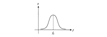
- the characteristic view which shows the relationship between the frequency of the transmission high frequency electric power in the electric power transmission by a resonance method, and received electric power.
- the relationship between the frequency of transmitted high-frequency power and the received power in power transmission by the resonance method is shown, (a) is a characteristic diagram when the coupling coefficient k is small, and (b) is a characteristic diagram when the coupling coefficient k is large.
- the characteristic view which shows the relationship between the frequency of the transmission high frequency electric power in Example 1 of this invention, and receiving power estimated value.
- the characteristic view which shows the relationship between the capacity
- the characteristic view which shows the relationship between the inductance of the primary coil in Example 2 of this invention, and received electric power estimated value.
- Examples 1 and 2 below show an embodiment in which the present invention is applied to a moving body, for example, an electric vehicle, which is supplied with electric power from an external power source without contact.
- FIG. 1 shows an apparatus configuration of the first embodiment.
- reference numeral 100 denotes a power supply apparatus that supplies power to a moving body 200 made of, for example, an electric vehicle in a non-contact manner.
- the power supply apparatus 100 includes, for example, an AC power supply 110 including a system power supply, a high-frequency power driver 120, a calculation apparatus 130 as calculation means, a primary coil 140 disposed near the ground on which the moving body 200 is placed, and control as control means.
- a device 150 is provided.
- the mobile body 200 is equipped with a secondary coil 210, a rectifier 220, a power storage device 230, and an electric motor 240 that drives the mobile body 200 with electric power stored in the power storage device 230.
- the high-frequency power driver 120 of the power supply apparatus 100 converts the power received from the AC power source 110 into high-frequency power that can be transmitted from the primary coil 140 to the secondary coil 210 on the moving body 200 side by resonating the magnetic field. The high frequency power thus supplied is supplied to the primary coil 140.
- the primary coil 140 is magnetically coupled to the secondary coil 210 of the moving body 200 by magnetic field resonance, and is configured to be able to supply power from the power supply apparatus 100 to the moving body 200.
- the arithmetic unit 130 estimates an equivalent circuit parameter of power transmission by the resonance method including the primary coil 140 and the secondary coil 210 from the transmission current / voltage of the high-frequency power driver 120.
- the control device 150 obtains the relationship between the frequency of the transmitted power of the primary coil 140 and the estimated value of the received power of the secondary coil 210 based on the equivalent circuit parameter estimated by the arithmetic device 130. Then, the frequency of the high-frequency power driver 120 is controlled so that the estimated received power is maximized.
- the secondary coil 210 is disposed at the lower part of the vehicle body of the moving body 200 and outputs the received power to the rectifier 220.
- Rectifier 220 rectifies high-frequency AC power received from secondary coil 210 and outputs the rectified power to power storage device 230.
- the primary coil 140 and the secondary coil 210 of the moving body 200 are magnetically coupled by magnetic field resonance, and the primary coil 140 Electric power is supplied to the next coil 210. Then, the electric power received by the secondary coil 210 is rectified by the rectifier 220 and stored in the power storage device 230.
- charging power can be supplied to the mobile body 200 wirelessly from a power source outside the mobile body, and the power storage device 230 mounted on the mobile body 200 can be charged.
- the arithmetic device 130 estimates the equivalent circuit parameters of the power transmission by the resonance method including the primary coil 140 on the power feeding device 100 side and the secondary coil 210 on the moving body 200 side, and from the estimated equivalent circuit parameters
- the control device 150 estimates the received power of the secondary coil 210 and controls the frequency of the transmitted power of the primary coil 140 so that the estimated received power is maximized.
- power can be supplied to the mobile body 200.
- power transmission by the resonance method is performed by using the inductance L 1 , stray capacitance C 1 , internal resistance R 1 of the primary coil 140, and the inductance L 2 , stray capacitance C 2 , and internal resistance R 2 of the secondary coil 210. It is known that it can be expressed as an equivalent circuit as shown in FIG. 3 (see, for example, Non-Patent Document 2).
- L m represents the mutual inductance of the two coils.
- L m can be expressed as follows.
- the frequency of the high-frequency power supplied to the primary coil 140 (frequency f of the transmitted high-frequency power) and the power supplied to the secondary coil 210 (received power P) have a relationship as shown in FIG. It has been known. That is, the supplied electric power becomes a maximum value at the resonance frequency f 0 of the two coils.
- FIG. 6A shows the case where the coupling coefficient k is small
- FIG. 6B shows the case where the coupling coefficient k is large. It is also known that the frequency width at which the maximum power can be transmitted is reduced if k is reduced (see Non-Patent Document 2).
- This resonance frequency f 0 changes with changes in the capacitance and inductance of the primary coil.
- the coupling coefficient k changes mainly depending on the core characteristics of the primary coil and the secondary coil and the positional relationship between the two coils.
- the power feeding apparatus 100 of the present invention first, power is supplied to the primary coil 140 with low power and power is transmitted from the primary coil 140 to the secondary coil 210, so that an equivalent circuit of the primary coil 140 and the secondary coil 210 is obtained.
- the parameters (inductance L 1 , stray capacitance C 1 , internal resistance R 1 , inductance L 2 , stray capacitance C 2 , internal resistance R 2 , mutual inductance L M of the equivalent circuit shown in FIG. 4) are estimated, and then large Electric power is supplied to the primary coil 140, power is transmitted from the primary coil 140 to the secondary coil 210, and charging of the power storage device 230 is started from the secondary coil 210.
- the primary coil when power is transmitted with the moving body 200 fixed (stopped) at an arbitrary position, first, the primary coil is operated with low power while changing the frequency of the high-frequency power output from the high-frequency power driver 120 within a changeable range. Power is transmitted to the secondary coil 210 via 140.
- the inductance L 1 , stray capacitance C 1 , and internal resistance R 1 of the equivalent circuit shown in FIG. 4 are parameters of the power supply device 100, and are obtained by calculation or simulation of circuit constants or trial operation.
- the arithmetic device 130 holds the data.
- the transmission current and the transmission voltage to the primary coil 140 at the time of the frequency change are sequentially recorded together with the frequency, and the transmission current and the transmission voltage in the entire frequency changeable range are recorded.
- the control device 150 estimates the received power of the secondary coil 210 according to the frequency by using the transmitted equivalent circuit parameter, and the frequency f-received power estimated value P es of the transmission high-frequency power as shown in FIG. To derive a relationship.
- the high-frequency power driver 120 is controlled so as to supply the high-frequency power at the frequency at which the estimated value P es of the received power is maximum, that is, the high-frequency power having the resonance frequency f 0 , and charging is started. Thereby, it is possible to supply power to the secondary coil 210 in a state where the received power is maximized without performing wireless communication, and highly efficient power transmission can be performed.
- FIG. 2 shows an apparatus configuration of the second embodiment, and the same parts as those in FIG.
- the moving body 200 in the second embodiment is configured in the same manner as the moving body 200 in the first embodiment.
- Reference numeral 300 denotes a power supply apparatus according to the second embodiment, which is different from the power supply apparatus 100 of FIG. 1 in that a primary device is used instead of the control device 150 that controls the high-frequency power driver 120 based on the equivalent circuit parameters obtained by the arithmetic device 130. It has a function of changing the capacity and inductance of the coil 140 and estimates the received power of the secondary coil 210 according to at least one of the capacity and inductance of the primary coil 140 from the equivalent circuit parameters estimated by the arithmetic unit 130.
- the adjustment device 160 for adjusting the resonance frequency of the primary coil 140 by changing at least one of the capacity and the inductance of the primary coil 140 so that the estimated received power is maximized is provided. It is configured identically.
- the primary coil 140 is supplied to the primary coil 140 with a small electric power, and power is transmitted from the primary coil 140 to the secondary coil 210.
- the parameters of the equivalent circuit 210 (inductance L 1 , stray capacitance C 1 , internal resistance R 1 , inductance L 2 , stray capacitance C 2 , internal resistance R 2 , mutual inductance L M of the equivalent circuit shown in FIG. 4) are estimated. Thereafter, a large amount of power is supplied to the primary coil 140, power is transmitted from the primary coil 140 to the secondary coil 210, and charging of the power storage device 230 is started from the secondary coil 210.
- the inductance L 1 , stray capacitance C 1 , and internal resistance R 1 of the equivalent circuit shown in FIG. 4 are parameters of the power supply apparatus 100, and are obtained by calculation or simulation of circuit constants or trial operation. Is held by the arithmetic unit 130, for example.
- the arithmetic device 130 sequentially records the transmission current and transmission voltage to the primary coil 140 when changing at least one of the capacitance and inductance, together with the capacitance and inductance, and records the transmission current and transmission voltage in the entire changeable range. To do.
- the adjustment device 160 estimates the received power of the secondary coil 210 according to the frequency by using the transmitted equivalent circuit parameter, and the primary coil capacitance C-received power estimated value P es as shown in FIG. relationship, or primary coil inductance L- received power estimate P es relationship as shown in FIG. 9, or derive both.
- the primary coil 140 is changed so that the estimated value P es of the received power becomes the maximum C 0 or L 0, and charging of the power storage device 230 is started.
- power can be supplied from the AC power source 110 to the moving body 200 in a state where the received power is maximized without performing wireless communication, and highly efficient power transmission can be performed.
- the present invention is not limited to an electric vehicle, and can be applied to other mobile objects to which power is supplied in a non-contact manner.
- the power source outside the mobile body is not limited to the AC power source, and may be configured to convert the power from the DC power source into high frequency power.
Landscapes
- Engineering & Computer Science (AREA)
- Power Engineering (AREA)
- Transportation (AREA)
- Mechanical Engineering (AREA)
- Computer Networks & Wireless Communication (AREA)
- Charge And Discharge Circuits For Batteries Or The Like (AREA)
- Current-Collector Devices For Electrically Propelled Vehicles (AREA)
- Electric Propulsion And Braking For Vehicles (AREA)
Abstract
【課題】無線通信を行なうことなく高効率の電力伝送を可能とする。 【解決手段】二次コイル210を備えた移動体200に対して、給電を行う給電装置100であって、前記二次コイル210と磁場の共鳴により磁気的に結合され、高周波電力を二次コイル210へ送電可能に構成された一次コイル140と、交流電源110の電力を、磁場を共鳴させて前記移動体200へ送電可能な高周波電力に変換し、前記一次コイル140に供給する高周波電力ドライバ120と、高周波電力ドライバ120の送電電流・電圧から、共鳴法による前記一次コイル140から二次コイル210への電力伝送の等価回路パラメータを推定する演算装置130と、演算装置130により推定された等価回路パラメータから、二次コイル210の受電電力を推定し、該推定した受電電力が最大となるように高周波電力ドライバ120を制御する制御装置150とを備えた。
Description
本発明は、移動体に搭載された蓄電装置に、移動体外部の電源から非接触で給電するための技術に関する。
近年、環境に配慮した移動体として、電気自動車などの電動車両が大きく注目されている。
これらの車両は、走行駆動力を発生する電動機と、その電動機に供給される電力を蓄える充電可能な蓄電装置とを搭載する。しかしながら、電気自動車に搭載できるほど小型・軽量の蓄電装置では大容量のものがない。そのため電気自動車の利用者は頻繁に充電を繰り返さなければならない。またその充電作業は重いケーブルを抜き挿ししなければならず手間となる。
その解決法として、電源コードや送電ケーブルを用いないワイヤレス送電がある。下記非特許文献1で提唱された共鳴法は電力を比較的長距離伝送することが可能な技術であり、近年特に注目されている。
また、磁界共振結合における自己共振周波数を利用したワイヤレス電力伝送は下記非特許文献2に記載され、ワイヤレス送電による給電装置は下記特許文献1~3に記載のものが提案されている。
"Wireless Power Transfer via Strongly Coupled Magnetic Resonances"、2007年7月6日、サイエンス(SCIENCE)、第317巻、pp.83-86
加藤昌樹、居村岳広、内田利之、堀洋一、「磁界共振結合における自己共振周波数を利用したワイヤレス電力伝送」、平成22年電気学会産業応用部門大会
しかしながら、前記共鳴法では、一次コイルと二次コイルの共振周波数を正確に合わせなければ高効率で電力伝送できないため、共振周波数を合わせる制御が必要となる。
また前記特許文献1では、電気自動車側で受電電力の検出を行い、通信により給電装置に受電状況を送信し、給電装置の制御を行う。この方法では、通信装置を装備することが必要であるため、電気自動車・給電装置ともにコスト高となってしまうだけでなく、通信方式が一致する電気自動車、給電装置の組み合わせでなければ、充電ができないという問題がある。
また前記特許文献2や特許文献3では、インピーダンスを測定することにより共振周波数の探索を行なっている。これらの提案では、インピーダンスの測定を周波数の走査によって行なっており、その結果、共振周波数の探索が走査周波数間隔で行なわれることになる。
共鳴法では、受電電力と送電高周波電力の周波数との関係を示す図5のように、Qが高く、共振がとても短い周波数範囲にあるため、これらの方法で共振周波数f0を求めるには非常に細かい周波数走査間隔によらなければ探索することができず、現実的ではない。また、探索した周波数は共振周波数f0とは異なるため、もっとも効率の高い周波数での電力伝送を行うことができない。
本発明は上記課題を解決するものであり、その目的は、無線通信を行なうことなく高効率の電力伝送を可能とした非接触給電装置、方法を提供することにある。
上記課題を解決するための請求項1に記載の非接触給電装置は、移動体外部の一次コイルと磁場の共鳴により磁気的に結合され、前記一次コイルから電力を受電可能に構成された二次コイルと、前記二次コイルが受電した電力を整流する整流器と、前記整流器によって整流された電力を蓄える蓄電装置と、前記蓄電装置から電力の供給を受けて駆動力を発生する電動機とを備えた移動体に対して、給電を行う給電装置であって、前記二次コイルと磁場の共鳴により磁気的に結合され、高周波電力を前記二次コイルへ送電可能に構成された一次コイルと、移動体外部の電力を、磁場を共鳴させて前記移動体へ送電可能な高周波電力に変換し、前記一次コイルに供給する高周波電力ドライバと、前記高周波電力ドライバの送電電流・電圧から、磁場の共鳴による前記一次コイルと二次コイルとの間の電力伝送の等価回路パラメータを推定する演算手段と、前記演算手段により推定された等価回路パラメータから、前記二次コイルの受電電力を推定し、該推定した受電電力が最大となるように送電電力の周波数を制御する制御手段と、を備えたことを特徴としている。
また、請求項2に記載の非接触給電装置は、請求項1において、前記制御手段は、前記演算手段により推定された等価回路パラメータから、送電電力に応じた前記二次コイルの受電電力を推定し、該推定した受電電力が最大となるように前記高周波電力ドライバの周波数を制御することを特徴としている。
また請求項3に記載の非接触給電装置は、請求項1において、前記制御手段が、前記演算手段により推定された等価回路パラメータから、前記一次コイルの容量およびインダクタンスの少なくとも一方に応じた前記二次コイルの受電電力を推定し、該推定した受電電力が最大となるように前記一次コイルの容量およびインダクタンスの少なくとも一方を変更して一次コイルの共振周波数を調整することを特徴としている。
また、請求項4に記載の非接触給電方法は、移動体外部の一次コイルと磁場の共鳴により磁気的に結合され、前記一次コイルから電力を受電可能に構成された二次コイルと、前記二次コイルが受電した電力を整流する整流器と、前記整流器によって整流された電力を蓄える蓄電装置と、前記蓄電装置から電力の供給を受けて駆動力を発生する電動機とを備えた移動体に対して、給電を行う給電方法であって、高周波電力ドライバが、移動体外部の電力を、磁場を共鳴させて前記移動体へ送電可能な高周波電力に変換し、該周波数を変化させながら前記一次コイルに供給する送電ステップと、演算手段が、前記送電ステップ実行中の高周波電力ドライバの送電電流・電圧から、磁場の共鳴による前記一次コイルと二次コイルとの間の電力伝送の等価回路パラメータを推定する等価回路パラメータ推定ステップと、制御手段が、前記推定された等価回路パラメータから、前記二次コイルの受電電力を推定する受電電力推定ステップと、前記推定された受電電力が最大となるように送電電力の周波数を制御する制御ステップと、を備えたことを特徴としている。
又請求項5に記載の非接触給電方法は、請求項4において、前記受電電力推定ステップは、前記等価回路パラメータ推定ステップにより推定された等価回路パラメータから、送電電力に応じた前記二次コイルの受電電力を推定し、前記制御ステップは、前記推定した受電電力が最大となるように前記高周波電力ドライバの周波数を制御することを特徴としている。
また請求項6に記載の非接触給電方法は、請求項4において、前記受電電力推定ステップは、前記等価回路パラメータ推定ステップにより推定された等価回路パラメータから、前記一次コイルの容量およびインダクタンスの少なくとも一方に応じた前記二次コイルの受電電力を推定し、前記制御ステップは、前記推定した受電電力が最大となるように前記一次コイルの容量およびインダクタンスの少なくとも一方を変更して一次コイルの共振周波数を調整することを特徴としている。
上記構成によれば、移動体への共鳴法によるワイヤレス送電において、移動体側の受電部分を最小の構成とすることでコストを削減でき、通信方式が一致する移動体と給電装置の組み合わせが不要で、どのような移動体へも適用が容易で、且つ無線通信を行なわずに受電電力が最大となる状態での給電装置から移動体への電力の供給が可能となり、高効率な電力伝送ができる。
(1)請求項1~3に記載の発明によれば、移動体、例えば電気自動車側で受電電力を検出し、その受電状況を無線通信により送信する必要がないため、電気自動車、給電装置ともに簡単な構成とすることができ、コストの低廉化を図ることができる。
また、従来のように通信方式が一致する電気自動車、給電装置の組み合わせとする必要はないので、どのような電気自動車(移動体)へも適用が容易である。
更に無線通信を行なわずに、受電電力が最大となる状態で給電装置から移動体への電力の供給が可能となる高効率な電力伝送を実施することができる。
(2)請求項4~6に記載の発明によれば、無線通信を行なわずに、受電電力が最大となる状態で送電が可能となる高効率な電力伝送を実施することができる。
(2)請求項4~6に記載の発明によれば、無線通信を行なわずに、受電電力が最大となる状態で送電が可能となる高効率な電力伝送を実施することができる。
以下、図面を参照しながら本発明の実施の形態を説明するが、本発明は下記の実施形態例に限定されるものではない。以下の実施例1、2は、本発明を、外部電源から非接触で給電される移動体、例えば電気自動車に適用した実施形態を示している。
図1は実施例1の装置構成を示している。図1において100は、例えば電気自動車から成る移動体200に非接触で給電を行う給電装置である。この給電装置100は、例えば系統電源から成る交流電源110、高周波電力ドライバ120、演算手段としての演算装置130、移動体200が置かれる地面近傍に配設された一次コイル140および制御手段としての制御装置150を備えている。
移動体200には、二次コイル210、整流器220、蓄電装置230および蓄電装置230に蓄えられた電力により移動体200を駆動させる電動機240が搭載されている。
前記給電装置100の高周波電力ドライバ120は、交流電源110から受ける電力を、磁場を共鳴させて一次コイル140から移動体200側の二次コイル210へ送電可能な高周波の電力に変換し、その変換した高周波電力を一次コイル140へ供給する。
一次コイル140は移動体200の二次コイル210と磁場の共鳴により磁気的に結合され、給電装置100から前記移動体200へ電力を供給可能に構成される。
演算装置130は、高周波電力ドライバ120の送電電流・電圧から、前記一次コイル140と二次コイル210を含む、共鳴法による電力伝送の等価回路パラメータを推定する。
制御装置150は、演算装置130で推定した等価回路パラメータをもとに、一次コイル140の送電電力の周波数と二次コイル210の受電電力の推定値の関係を求める。そして、推定した受電電力が最大となるように、高周波電力ドライバ120の周波数を制御する。
二次コイル210は、移動体200の車体下部に配設され、受電した電力を整流器220へ出力する。整流器220は、二次コイル210から受ける高周波の交流電力を整流して蓄電装置230へ出力する。
図1の装置において、交流電源110から一次コイル140に電力が供給されると、一次コイル140と移動体200の二次コイル210とが磁場の共鳴により磁気的に結合され、一次コイル140から二次コイル210へ電力が供給される。そして、二次コイル210によって受電された電力は、整流器220によって整流されて蓄電装置230に蓄えられる。
したがって、本実施例1の給電装置100によれば、移動体外部の電源からワイヤレスで充電電力を移動体200へ供給し、移動体200に搭載された蓄電装置230を充電することができる。
この際、演算装置130によって、給電装置100側の一次コイル140と移動体200側の二次コイル210を含む、共鳴法による電力伝送の等価回路パラメータを推定し、該推定された等価回路パラメータから、制御装置150が二次コイル210の受電電力を推定し、その推定した受電電力が最大となるように一次コイル140の送電電力の周波数を制御するので、移動体外部の交流電源110から効率的に移動体200へ電力を供給することができる。
次に、上記のように構成された装置の動作を詳細に説明する。
まず、共鳴法による電力伝送は、一次コイル140のインダクタンスL1、浮遊容量C1、内部抵抗R1、および二次コイル210のインダクタンスL2、浮遊容量C2、内部抵抗R2を用いることにより、図3のような等価回路として表すことができることが知られている(例えば非特許文献2参照)。
ここで、Lmは2つのコイルの相互インダクタンスを示す。結合係数kを導入するとLmは以下のように表せる。

また、図3の等価回路を変形すると、図4の等価回路になる。
共鳴法による電力伝送では、一次コイル140へ供給する高周波電力の周波数(送電高周波電力の周波数f)と二次コイル210に供給される電力(受電電力P)は図5のような関係となることが知られている。すなわち、供給される電力は2つのコイルの共振周波数f0にて最大値となる。
また、送電高周波電力の周波数fと二次コイル210に供給される受電電力Pの関係は、結合係数kが小さい場合を示す図6(a)、結合係数kが大きい場合を示す図6(b)のように変化し、kが小さくなれば、最大電力を送信できる周波数幅が小さくなることも知られている(非特許文献2参照)。
この共振周波数f0は一次コイルの容量およびインダクタンスの変化により変化する。また結合係数kは主に一次コイルと二次コイルのコアの特性や2つのコイルの位置関係により変化する。
本発明の給電装置100では、まず小電力で一次コイル140へ電力を供給して一次コイル140から二次コイル210に電力伝送が行われることにより、一次コイル140と二次コイル210の等価回路のパラメータ(図4に示した等価回路のインダクタンスL1、浮遊容量C1、内部抵抗R1、インダクタンスL2、浮遊容量C2、内部抵抗R2、相互インダクタンスLM)を推定し、その後、大電力を一次コイル140へ供給して、一次コイル140から二次コイル210に電力伝送が行われ、この二次コイル210から蓄電装置230の充電を開始する。
すなわち図1において、移動体200を任意の位置に固定(停車)して電力伝送を行う時、まず高周波電力ドライバ120の出力する高周波電力の周波数を変化可能範囲で変化させながら小電力で一次コイル140を介して二次コイル210に電力伝送が行われる。
ここで、図4に示した等価回路のインダクタンスL1、浮遊容量C1、内部抵抗R1は給電装置100のパラメータであり、回路定数の計算やシミュレーション、または試運転などにより求めておき、それらのデータは例えば演算装置130が保持する。
演算装置130では、前記周波数変化時の一次コイル140への送信電流および送信電圧を周波数とともに逐次記録し、周波数の変化可能範囲全ての送信電流および送信電圧を記録する。
これにより、図4に示した等価回路のインダクタンスL2、浮遊容量C2、内部抵抗R2、相互インダクタンスLMを推定する。
そして前記保持していたインダクタンスL1、浮遊容量C1、内部抵抗R1および推定したインダクタンスL2、浮遊容量C2、内部抵抗R2、相互インダクタンスLM(図4の等価回路のパラメータ)を制御装置150に送信する。
制御装置150では、前記送信された等価回路パラメータを用いることにより、周波数に応じた二次コイル210の受電電力を推定し、図7のような送電高周波電力の周波数f-受電電力推定値Pesの関係を導き出す。
その後、受電電力の推定値Pesが最大となる周波数、すなわち共振周波数f0の高周波電力を高周波電力ドライバ120から供給させるよう、高周波電力ドライバ120を制御し、充電を開始する。これにより、無線通信を行なわずに受電電力が最大となる状態で二次コイル210への電力の供給が可能となり、高効率の電力伝送ができる。
図2は実施例2の装置構成を示しており、図1と同一部分は同一符号をもって示している。本実施例2における移動体200は、実施例1の移動体200と同一に構成されている。
300は本実施例2の給電装置であり、図1の給電装置100と異なる点は、演算装置130で求めた等価回路パラメータに基づいて高周波電力ドライバ120を制御する制御装置150に代えて、一次コイル140の容量およびインダクタンスを変更させる機能を有し、演算装置130により推定された等価回路パラメータから、前記一次コイル140の容量およびインダクタンスの少なくとも一方に応じた二次コイル210の受電電力を推定し、該推定した受電電力が最大となるように一次コイル140の容量およびインダクタンスの少なくとも一方を変更して一次コイル140の共振周波数を調整する調整装置160を設けた点にあり、その他は図1と同一に構成されている。
本実施例2においても、前記実施例1と同様に、まず小電力で一次コイル140へ供給して一次コイル140から二次コイル210に電力伝送が行われることにより、一次コイル140と二次コイル210の等価回路のパラメータ(図4に示した等価回路のインダクタンスL1、浮遊容量C1、内部抵抗R1、インダクタンスL2、浮遊容量C2、内部抵抗R2、相互インダクタンスLM)を推定し、その後、大電力を一次コイル140へ供給して、一次コイル140から二次コイル210に電力伝送が行われ、この二次コイル210から蓄電装置230の充電を開始する。
すなわち図2において、移動体200を任意の位置に固定(停車)して電力伝送を行う時、調整装置160により一次コイル140の容量(C1)およびインダクタンス(L1)の少なくとも一方を変化可能範囲で変化させながら小電力で一次コイル140を介して二次コイル210に電力伝送が行われる。
尚、図4に示した等価回路のインダクタンスL1、浮遊容量C1、内部抵抗R1は給電装置100のパラメータであり、回路定数の計算やシミュレーション、または試運転などにより求めておき、それらのデータは例えば演算装置130が保持する。
演算装置130では、前記容量およびインダクタンスの少なくとも一方を変化させた時の一次コイル140への送信電流および送信電圧を、容量およびインダクタンスとともに逐次記録し、変化可能範囲全ての送信電流および送信電圧を記録する。
これにより、図4に示した等価回路のインダクタンスL2、浮遊容量C2、内部抵抗R2、相互インダクタンスLMを推定する。
そして前記保持していたインダクタンスL1、浮遊容量C1、内部抵抗R1および推定したインダクタンスL2、浮遊容量C2、内部抵抗R2、相互インダクタンスLM(図4の等価回路のパラメータ)を調整装置160に送信する。
調整装置160では、前記送信された等価回路パラメータを用いることにより、周波数に応じた二次コイル210の受電電力を推定し、図8のような一次コイルの容量C-受電電力推定値Pesの関係、または図9のような一次コイルのインダクタンスL-受電電力推定値Pesの関係、あるいはその両方を導き出す。
その後、受電電力の推定値Pesが最大となるC0またはL0となるよう一次コイル140を変化させ、蓄電装置230への充電を開始する。これにより、無線通信を行なわずに受電電力が最大となる状態で交流電源110から移動体200に電力の供給が可能となり、高効率の電力伝送ができる。
尚、本発明は電気自動車に限らず、非接触で電力の供給が行われる他の移動体にも適用することができる。
また、移動体外部の電源も交流電源に限らず直流電源からの電力を高周波電力に変換する構成であっても良い。
100、300…給電装置
110…交流電源
120…高周波電力ドライバ
130…演算装置
140…一次コイル
150…制御装置
160…調整装置
200…移動体
210…二次コイル
220…整流器
230…蓄電装置
240…電動機
110…交流電源
120…高周波電力ドライバ
130…演算装置
140…一次コイル
150…制御装置
160…調整装置
200…移動体
210…二次コイル
220…整流器
230…蓄電装置
240…電動機
Claims (6)
- 移動体外部の一次コイルと磁場の共鳴により磁気的に結合され、前記一次コイルから電力を受電可能に構成された二次コイルと、前記二次コイルが受電した電力を整流する整流器と、前記整流器によって整流された電力を蓄える蓄電装置と、前記蓄電装置から電力の供給を受けて駆動力を発生する電動機とを備えた移動体に対して、給電を行う給電装置であって、
前記二次コイルと磁場の共鳴により磁気的に結合され、高周波電力を前記二次コイルへ送電可能に構成された一次コイルと、
移動体外部の電力を、磁場を共鳴させて前記移動体へ送電可能な高周波電力に変換し、前記一次コイルに供給する高周波電力ドライバと、
前記高周波電力ドライバの送電電流・電圧から、磁場の共鳴による前記一次コイルと二次コイルとの間の電力伝送の等価回路パラメータを推定する演算手段と、
前記演算手段により推定された等価回路パラメータから、前記二次コイルの受電電力を推定し、該推定した受電電力が最大となるように送電電力の周波数を制御する制御手段と、を備えたことを特徴とする非接触給電装置。 - 前記制御手段は、前記演算手段により推定された等価回路パラメータから、送電電力に応じた前記二次コイルの受電電力を推定し、該推定した受電電力が最大となるように前記高周波電力ドライバの周波数を制御することを特徴とする請求項1に記載の非接触給電装置。
- 前記制御手段は、前記演算手段により推定された等価回路パラメータから、前記一次コイルの容量およびインダクタンスの少なくとも一方に応じた前記二次コイルの受電電力を推定し、該推定した受電電力が最大となるように前記一次コイルの容量およびインダクタンスの少なくとも一方を変更して一次コイルの共振周波数を調整することを特徴とする請求項1に記載の非接触給電装置。
- 移動体外部の一次コイルと磁場の共鳴により磁気的に結合され、前記一次コイルから電力を受電可能に構成された二次コイルと、前記二次コイルが受電した電力を整流する整流器と、前記整流器によって整流された電力を蓄える蓄電装置と、前記蓄電装置から電力の供給を受けて駆動力を発生する電動機とを備えた移動体に対して、給電を行う給電方法であって、
高周波電力ドライバが、移動体外部の電力を、磁場を共鳴させて前記移動体へ送電可能な高周波電力に変換し、該周波数を変化させながら前記一次コイルに供給する送電ステップと、
演算手段が、前記送電ステップ実行中の高周波電力ドライバの送電電流・電圧から、磁場の共鳴による前記一次コイルと二次コイルとの間の電力伝送の等価回路パラメータを推定する等価回路パラメータ推定ステップと、
制御手段が、前記推定された等価回路パラメータから、前記二次コイルの受電電力を推定する受電電力推定ステップと、
前記推定された受電電力が最大となるように送電電力の周波数を制御する制御ステップと、を備えたことを特徴とする非接触給電方法。 - 前記受電電力推定ステップは、前記等価回路パラメータ推定ステップにより推定された等価回路パラメータから、送電電力に応じた前記二次コイルの受電電力を推定し、
前記制御ステップは、前記推定した受電電力が最大となるように前記高周波電力ドライバの周波数を制御することを特徴とする請求項4に記載の非接触給電方法。 - 前記受電電力推定ステップは、前記等価回路パラメータ推定ステップにより推定された等価回路パラメータから、前記一次コイルの容量およびインダクタンスの少なくとも一方に応じた前記二次コイルの受電電力を推定し、
前記制御ステップは、前記推定した受電電力が最大となるように前記一次コイルの容量およびインダクタンスの少なくとも一方を変更して一次コイルの共振周波数を調整することを特徴とする請求項4に記載の非接触給電方法。
Priority Applications (3)
| Application Number | Priority Date | Filing Date | Title |
|---|---|---|---|
| EP12739803.0A EP2658086A4 (en) | 2011-01-25 | 2012-01-25 | CONTACTLESS POWER SUPPLY AND CONTACTLESS POWER SUPPLY PROCESS |
| CN201280006385.1A CN103339823B (zh) | 2011-01-25 | 2012-01-25 | 非接触电力馈送装置和非接触电力馈送方法 |
| US13/981,519 US9096138B2 (en) | 2011-01-25 | 2012-01-25 | Contactless power feeding apparatus and contactless power feeding method |
Applications Claiming Priority (2)
| Application Number | Priority Date | Filing Date | Title |
|---|---|---|---|
| JP2011013067A JP5732870B2 (ja) | 2011-01-25 | 2011-01-25 | 非接触給電装置および非接触給電方法 |
| JP2011-013067 | 2011-01-25 |
Publications (1)
| Publication Number | Publication Date |
|---|---|
| WO2012102302A1 true WO2012102302A1 (ja) | 2012-08-02 |
Family
ID=46580867
Family Applications (1)
| Application Number | Title | Priority Date | Filing Date |
|---|---|---|---|
| PCT/JP2012/051534 Ceased WO2012102302A1 (ja) | 2011-01-25 | 2012-01-25 | 非接触給電装置および非接触給電方法 |
Country Status (5)
| Country | Link |
|---|---|
| US (1) | US9096138B2 (ja) |
| EP (1) | EP2658086A4 (ja) |
| JP (1) | JP5732870B2 (ja) |
| CN (1) | CN103339823B (ja) |
| WO (1) | WO2012102302A1 (ja) |
Cited By (1)
| Publication number | Priority date | Publication date | Assignee | Title |
|---|---|---|---|---|
| WO2015009042A1 (en) * | 2013-07-17 | 2015-01-22 | Samsung Electronics Co., Ltd. | Method and apparatus for detecting coupling region |
Families Citing this family (10)
| Publication number | Priority date | Publication date | Assignee | Title |
|---|---|---|---|---|
| WO2015182097A1 (ja) * | 2014-05-27 | 2015-12-03 | パナソニックIpマネジメント株式会社 | 非接触給電装置およびそれを用いた非接触給電システム |
| WO2016147663A1 (ja) * | 2015-03-19 | 2016-09-22 | パナソニックIpマネジメント株式会社 | 非接触給電装置及び非接触給電システム |
| US10418863B1 (en) | 2015-09-28 | 2019-09-17 | Apple Inc. | Charging system |
| CN106379190B (zh) * | 2016-11-03 | 2019-03-22 | 中国科学院电工研究所 | 一种负载自适应的电动汽车无线充电系统 |
| CN110692176A (zh) * | 2017-06-02 | 2020-01-14 | 日本电产株式会社 | 输电装置、无线电力传输系统以及控制装置 |
| JP6798953B2 (ja) * | 2017-09-05 | 2020-12-09 | 本田技研工業株式会社 | 電力供給システム |
| JP6803818B2 (ja) * | 2017-09-05 | 2020-12-23 | 本田技研工業株式会社 | 電力供給システム |
| CN108382242B (zh) * | 2018-03-15 | 2020-09-08 | 美澳视界(厦门)智能科技有限公司 | 电动汽车无线快速充电方法 |
| JP6930953B2 (ja) * | 2018-09-10 | 2021-09-01 | 株式会社東芝 | 送電装置および受電装置 |
| EP3988022A4 (en) * | 2019-06-21 | 2023-07-26 | UNIST (Ulsan National Institute of Science and Technology) | RESONATOR ASSEMBLY FOR BIOMETRIC AND BIOSENSOR DETECTION USING ELECTROMAGNETIC WAVES |
Citations (3)
| Publication number | Priority date | Publication date | Assignee | Title |
|---|---|---|---|---|
| JP4453741B2 (ja) | 2007-10-25 | 2010-04-21 | トヨタ自動車株式会社 | 電動車両および車両用給電装置 |
| JP2010233442A (ja) | 2009-03-06 | 2010-10-14 | Nissan Motor Co Ltd | 非接触電力供給装置及び方法 |
| JP2010252446A (ja) | 2009-04-13 | 2010-11-04 | Nippon Soken Inc | 非接触給電設備、非接触受電装置および非接触給電システム |
Family Cites Families (13)
| Publication number | Priority date | Publication date | Assignee | Title |
|---|---|---|---|---|
| CA2715916A1 (en) * | 2008-02-22 | 2009-08-27 | David W. Baarman | Inductive power supply system with battery type detection |
| JP4488090B2 (ja) * | 2008-06-09 | 2010-06-23 | トヨタ自動車株式会社 | 車両および車両の制御方法 |
| CN102171777A (zh) * | 2008-10-02 | 2011-08-31 | 丰田自动车株式会社 | 自谐振线圈、非接触电力传输装置以及车辆 |
| JP2010136464A (ja) * | 2008-12-02 | 2010-06-17 | Casio Computer Co Ltd | 電力伝送装置および電力伝送方法 |
| JP2010193598A (ja) * | 2009-02-17 | 2010-09-02 | Nippon Soken Inc | 非接触給電設備および非接触給電システム |
| JP5621203B2 (ja) * | 2009-03-30 | 2014-11-12 | 富士通株式会社 | 無線電力供給システム、無線電力供給方法 |
| JP5387201B2 (ja) * | 2009-07-23 | 2014-01-15 | ソニー株式会社 | 非接触給電システム、非接触中継装置、非接触受電装置および非接触給電方法 |
| KR101423406B1 (ko) * | 2009-11-18 | 2014-07-24 | 가부시끼가이샤 도시바 | 무선 전력 전송 장치 |
| JP5016069B2 (ja) * | 2010-01-12 | 2012-09-05 | トヨタ自動車株式会社 | 電力伝送システムおよび車両用給電装置 |
| JP5146488B2 (ja) * | 2010-05-26 | 2013-02-20 | トヨタ自動車株式会社 | 給電システムおよび車両 |
| US9552920B2 (en) * | 2010-07-28 | 2017-01-24 | General Electric Company | Contactless power transfer system |
| KR101842308B1 (ko) * | 2010-10-29 | 2018-03-26 | 퀄컴 인코포레이티드 | 커플링된 기생 공진기들을 통한 무선 에너지 전송 |
| JP2012143117A (ja) * | 2011-01-06 | 2012-07-26 | Toyota Industries Corp | 非接触電力伝送装置 |
-
2011
- 2011-01-25 JP JP2011013067A patent/JP5732870B2/ja not_active Expired - Fee Related
-
2012
- 2012-01-25 WO PCT/JP2012/051534 patent/WO2012102302A1/ja not_active Ceased
- 2012-01-25 CN CN201280006385.1A patent/CN103339823B/zh not_active Expired - Fee Related
- 2012-01-25 US US13/981,519 patent/US9096138B2/en not_active Expired - Fee Related
- 2012-01-25 EP EP12739803.0A patent/EP2658086A4/en not_active Withdrawn
Patent Citations (3)
| Publication number | Priority date | Publication date | Assignee | Title |
|---|---|---|---|---|
| JP4453741B2 (ja) | 2007-10-25 | 2010-04-21 | トヨタ自動車株式会社 | 電動車両および車両用給電装置 |
| JP2010233442A (ja) | 2009-03-06 | 2010-10-14 | Nissan Motor Co Ltd | 非接触電力供給装置及び方法 |
| JP2010252446A (ja) | 2009-04-13 | 2010-11-04 | Nippon Soken Inc | 非接触給電設備、非接触受電装置および非接触給電システム |
Non-Patent Citations (4)
| Title |
|---|
| "Wireless Power Transfer via Strongly Coupled Magnetic Resonances", SCIENCE, vol. 317, 6 July 2007 (2007-07-06), pages 83 - 86 |
| MASAKI KATO; TAKEHIRO IMURA; TOSHIYUKI UCHIDA; YOICHI HORI: "Wireless Power Feeding using Self-Resonant Frequency via Magnetic Resonant Coupling", IEEJ INDUSTRY APPLICATIONS SOCIETY |
| NORIYUKI NAKAJIMA ET AL.: "Experimental Research on Element Composition of Contact less Power Station for Moving Electric Loads", NATIONAL CONVENTION RECORD I.E.E. JAPAN, vol. 2-169, 19 March 2008 (2008-03-19), pages 193, XP008171420 * |
| See also references of EP2658086A4 |
Cited By (4)
| Publication number | Priority date | Publication date | Assignee | Title |
|---|---|---|---|---|
| WO2015009042A1 (en) * | 2013-07-17 | 2015-01-22 | Samsung Electronics Co., Ltd. | Method and apparatus for detecting coupling region |
| KR20150010029A (ko) * | 2013-07-17 | 2015-01-28 | 삼성전자주식회사 | 커플링 영역 검출 방법 및 장치 |
| CN105379066A (zh) * | 2013-07-17 | 2016-03-02 | 三星电子株式会社 | 用于检测耦合区域的方法和设备 |
| KR102113853B1 (ko) | 2013-07-17 | 2020-06-03 | 삼성전자주식회사 | 커플링 영역 검출 방법 및 장치 |
Also Published As
| Publication number | Publication date |
|---|---|
| JP5732870B2 (ja) | 2015-06-10 |
| CN103339823B (zh) | 2016-05-18 |
| EP2658086A1 (en) | 2013-10-30 |
| CN103339823A (zh) | 2013-10-02 |
| US20130335017A1 (en) | 2013-12-19 |
| EP2658086A4 (en) | 2014-11-19 |
| US9096138B2 (en) | 2015-08-04 |
| JP2012157127A (ja) | 2012-08-16 |
Similar Documents
| Publication | Publication Date | Title |
|---|---|---|
| JP5732870B2 (ja) | 非接触給電装置および非接触給電方法 | |
| CN102640395B (zh) | 非接触供电设备、车辆以及非接触供电系统的控制方法 | |
| US9142986B2 (en) | Coil unit, non-contact power transmitting apparatus, non-contact power receiving apparatus, vehicle, and non-contact power supply system | |
| CN103270669B (zh) | 非接触供电系统、车辆、供电设备及非接触供电系统的控制方法 | |
| US9963040B2 (en) | Non-contact power supply system, and power transmission device and vehicle used therein | |
| CN103026583B (zh) | 无线供电系统及无线供电方法 | |
| US9073447B2 (en) | Power transmitting device, vehicle, and contactless power transfer system | |
| CN104025422B (zh) | 非接触受电装置、非接触送电装置以及非接触送电受电系统 | |
| JP2010074937A (ja) | 非接触受電装置およびそれを備える車両 | |
| WO2013129451A1 (ja) | 電力伝送システム | |
| US9680331B2 (en) | System and method for frequency protection in wireless charging | |
| JP2011167036A (ja) | 車両用給電装置および受電装置 | |
| JP2013074685A (ja) | 電力伝送システム | |
| JP2013034367A (ja) | 非接触給電装置 | |
| CN105358365B (zh) | 供电装置及供电方法 | |
| Amin et al. | Design and simulation of wireless stationary charging system for hybrid electric vehicle using inductive power pad in parking garage | |
| Menon et al. | Efficient wireless power transfer using underground relay coils | |
| JP5888201B2 (ja) | 受電機器、及び非接触電力伝送装置 | |
| JP2018078773A (ja) | 無線給電装置、及び無線給電方法 | |
| JP5825882B2 (ja) | 給電システム | |
| JP2013157944A (ja) | アンテナ | |
| Uchida et al. | An examination of optimizing input impedance for wireless power transfer operating with high power condition | |
| WO2014030689A1 (ja) | 非接触電力伝送装置および受電機器 | |
| CN114243936A (zh) | 充电控制系统及充电控制方法 | |
| Student | WiTricity-Wireless Power Transfer by Non-radiative Method |
Legal Events
| Date | Code | Title | Description |
|---|---|---|---|
| 121 | Ep: the epo has been informed by wipo that ep was designated in this application |
Ref document number: 12739803 Country of ref document: EP Kind code of ref document: A1 |
|
| WWE | Wipo information: entry into national phase |
Ref document number: 13981519 Country of ref document: US |
|
| NENP | Non-entry into the national phase |
Ref country code: DE |
|
| REEP | Request for entry into the european phase |
Ref document number: 2012739803 Country of ref document: EP |
|
| WWE | Wipo information: entry into national phase |
Ref document number: 2012739803 Country of ref document: EP |