WO2012102376A1 - Structure de ferrure d'assemblage de montant, et base plate équipée de celle-ci - Google Patents
Structure de ferrure d'assemblage de montant, et base plate équipée de celle-ci Download PDFInfo
- Publication number
- WO2012102376A1 WO2012102376A1 PCT/JP2012/051792 JP2012051792W WO2012102376A1 WO 2012102376 A1 WO2012102376 A1 WO 2012102376A1 JP 2012051792 W JP2012051792 W JP 2012051792W WO 2012102376 A1 WO2012102376 A1 WO 2012102376A1
- Authority
- WO
- WIPO (PCT)
- Prior art keywords
- fitting
- fitting portion
- column
- strut
- peripheral surface
- Prior art date
- Legal status (The legal status is an assumption and is not a legal conclusion. Google has not performed a legal analysis and makes no representation as to the accuracy of the status listed.)
- Ceased
Links
Images






Classifications
-
- A—HUMAN NECESSITIES
- A47—FURNITURE; DOMESTIC ARTICLES OR APPLIANCES; COFFEE MILLS; SPICE MILLS; SUCTION CLEANERS IN GENERAL
- A47B—TABLES; DESKS; OFFICE FURNITURE; CABINETS; DRAWERS; GENERAL DETAILS OF FURNITURE
- A47B87/00—Sectional furniture, i.e. combinations of complete furniture units, e.g. assemblies of furniture units of the same kind such as linkable cabinets, tables, racks or shelf units
- A47B87/02—Sectional furniture, i.e. combinations of complete furniture units, e.g. assemblies of furniture units of the same kind such as linkable cabinets, tables, racks or shelf units stackable ; stackable and linkable
- A47B87/0207—Stackable racks, trays or shelf units
- A47B87/0215—Stackable frames, or frame elements, with upright parts connected by inserting the ends or tips of the uprights, e.g. at the corners, into the uprights of the next frame or frame element, e.g. coaxial tubular ends
-
- F—MECHANICAL ENGINEERING; LIGHTING; HEATING; WEAPONS; BLASTING
- F16—ENGINEERING ELEMENTS AND UNITS; GENERAL MEASURES FOR PRODUCING AND MAINTAINING EFFECTIVE FUNCTIONING OF MACHINES OR INSTALLATIONS; THERMAL INSULATION IN GENERAL
- F16B—DEVICES FOR FASTENING OR SECURING CONSTRUCTIONAL ELEMENTS OR MACHINE PARTS TOGETHER, e.g. NAILS, BOLTS, CIRCLIPS, CLAMPS, CLIPS OR WEDGES; JOINTS OR JOINTING
- F16B12/00—Jointing of furniture or the like, e.g. hidden from exterior
- F16B12/40—Joints for furniture tubing
- F16B12/42—Joints for furniture tubing connecting furniture tubing to non-tubular parts
-
- A—HUMAN NECESSITIES
- A47—FURNITURE; DOMESTIC ARTICLES OR APPLIANCES; COFFEE MILLS; SPICE MILLS; SUCTION CLEANERS IN GENERAL
- A47B—TABLES; DESKS; OFFICE FURNITURE; CABINETS; DRAWERS; GENERAL DETAILS OF FURNITURE
- A47B87/00—Sectional furniture, i.e. combinations of complete furniture units, e.g. assemblies of furniture units of the same kind such as linkable cabinets, tables, racks or shelf units
- A47B87/02—Sectional furniture, i.e. combinations of complete furniture units, e.g. assemblies of furniture units of the same kind such as linkable cabinets, tables, racks or shelf units stackable ; stackable and linkable
- A47B87/0207—Stackable racks, trays or shelf units
- A47B87/0223—Shelves stackable by means of poles or tubular members as distance-holders therebetween
- A47B2087/023—Shelves stackable by means of poles or tubular members as distance-holders therebetween the shelves being held in intermediate connection elements between the tubular members
Definitions
- the present invention relates to a column joint structure in which a column joint having no play is obtained only by fitting between pipes without using pins or bolts, and a flat base using the column coupling structure.
- the assembly shelf disclosed in Japanese Patent Application Laid-Open No. 2010-233769 has a symmetrical shape around the column axis, and a plurality of engaging projections are formed at regular or irregular intervals in the longitudinal direction on both side surfaces of the main column.
- a pair of coupling members that are attached so as to sandwich the support column from both sides and a third engagement portion that engages with the second engagement portion are formed at substantially four corners by using a half region in the hand direction. The shelf member thus assembled is assembled.
- a single-stage or multi-stage flat table using a large flat plate having a large mounting area as a shelf board is known.
- the shelf plate and the column are generally formed by screwing a bolt screw formed at the end of the column and a screw hole formed in the shelf plate.
- the method of fixing the column to the shelf plate by screwing in the flat table is still not a simple mounting method, and particularly the formation of the bolt screw on the resin pipe member complicates the manufacturing process. It was something to do.
- the assembly shelf disclosed in Japanese Patent Application Laid-Open No. 2010-233769 cannot be supported when it enters inside from the end of the shelf because the end of the shelf is supported by the support column.
- the assembly shelf fixing device disclosed in Japanese Patent Application Laid-Open No. 2005-21573 and the shelf mounting device disclosed in Japanese Patent Application Laid-Open No. 2006-14791 both use pins and bolts having a specific shape as fixing members, so that assembly is easy. It can not be said.
- this invention solves the said subject, Comprising: The 1st collar part extended outside from the outer peripheral surface of this 1st support
- a first strut having a pipe-like first fitting portion extending in the direction of the first strut, and a second flange portion extending outward from the outer peripheral surface of the second strut main-body portion at one end of the pipe-like second strut body portion
- a second support column having a pipe-like second fitting portion extending in the direction, and a shelf board having a through hole into which the first fitting portion is fitted by press fitting, and an inner peripheral surface of the first fitting portion
- An unevenness is formed on the peripheral surface, or an unevenness is formed on the outer peripheral surface of the first fitting portion and the outer peripheral surface of the second fitting portion, and the first fitting is made in the through hole of the shelf board.
- the second fitting part is press-fitted into the
- the present invention provides a column having a pipe-shaped column main body at one end thereof, a flange extending outward from the outer peripheral surface of the column main column, a pipe-shaped fitting unit extending in the fitting side direction, and a cap top plate
- a cap having a pipe-like fitting portion having an outer diameter smaller than the outer diameter of the cap top plate extending from the back surface of the cap to the fitting side, and a shelf having a through-hole into which the fitting portion of the column is fitted by press-fitting And forming irregularities on the outer peripheral surface and inner peripheral surface of the fitting portion of the support column, or forming irregularities on the outer peripheral surface of the fitting portion of the support column and the outer peripheral surface of the fitting portion of the cap.
- the present invention provides a strut having a pipe-like fitting portion extending outwardly from an outer peripheral surface of the column-like main body portion and a pipe-like fitting portion extending in the fitting side direction at one end of the pipe-like column main body portion.
- a base cap having a pipe-like fitting portion having an outer diameter smaller than the outer diameter of the base extending in the direction of the fitting side from the surface, and a shelf having a through hole into which the fitting portion of the base cap fits by press fitting An unevenness is formed on the outer peripheral surface and the inner peripheral surface of the fitting portion of the column, or the outer peripheral surface of the fitting portion of the column and the outer peripheral surface of the fitting portion of the base cap A fitting portion of the base cap is press-fitted into the through hole of the shelf plate, and the fitting portion of the column is fitted into the fitting portion of the base cap by press-fitting.
- Column joint structure obtained by sandwiching a shelf board between a base and a base of the base cap It is intended to provide.
- the second fitting portion of the second column is press-fitted into the first fitting portion of the first column.
- the fitting by this press-fitting is a fitting by press contact between the inner peripheral surface of the first fitting portion and the unevenness of the outer peripheral surface of the two fitting portions, or the unevenness of the inner peripheral surface of the first fitting portion. Since the fitting is performed by pressure contact with the outer peripheral surface of the two fitting portions, the first support column and the second support column can be fitted with no backlash. Further, the fitting of the shelf board and the first support column is a fitting by press-contact between the inner peripheral surface of the through hole of the shelf board and the unevenness of the first fitting part, and further, the first collar part and the second collar part.
- the shelf board is sandwiched between the two, a fitting without backlash is obtained. Moreover, since the 1st fitting part of a 1st support
- the above-mentioned joining is composed of a strut joint structure composed of a strut having the same structure as the first strut, a specific cap and a shelf, and a strut having the same structure as the second strut, a specific base cap and a shelf. The same effect can be obtained with the column joint structure.
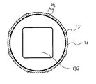
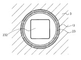
- FIG. 3 is a view taken along the line XX in FIG. 2 (the description of the first flange 12 is omitted).
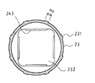
- FIG. 3 is a view taken along line YY in FIG. 2 (the description of the second flange portion 22 is omitted).
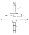
- FIG. 2 is a view showing a state in which a first support column is fitted to a shelf board in the support column joint structure of FIG. 1.
- FIG. 6 is a view showing a state where the second support column is fitted in the support joint structure of FIG. 5.
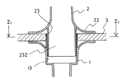
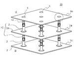
- FIG. 8 is a view taken along line Z 1 -Z 1 of FIG. It is a perspective view of the flat stand of this invention.
- FIG. 10 is an enlarged cross-sectional view of a circle (a column joint structure according to the second embodiment of the present invention) indicated by a two-dot chain line in FIG. 9. It is a perspective view of a cap.
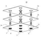
- FIG. 11 is a view taken along the line Z 2 -Z 2 of FIG. It is the perspective view seen from the bottom face side of the flat base of this invention.
- FIG. 10 is an enlarged cross-sectional view of a circle (a column joint structure according to the second embodiment of the present invention) indicated by a two-dot chain line in FIG. 9. It is a perspective view of a cap.
- FIG. 11 is a view taken along the line Z 2 -Z 2 of FIG. It is the perspective view seen from the bottom face side of the flat base of this invention.
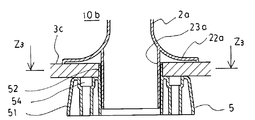
- FIG. 14 is an enlarged cross-sectional view of a circle (a column joint structure in a third embodiment of the present invention) indicated by a two-dot chain line in FIG. 13. It is a perspective view of a base cap.
- FIG. 15 is a view taken along the line Z 3 -Z 3 of FIG. It is sectional drawing of a 2nd support
- the strut joint structure 10 is obtained by assembling the first strut 1, the second strut 2, and the shelf board 3.
- the first strut 1 and the second strut 2 are made of resin.
- the first support column 1 has a first flange 12 extending outward from the outer peripheral surface of the first support column main body 11 at one end of the pipe-shaped first support column main body 11 (on the fitting side with the second support column 2).
- a cylindrical first fitting portion 13 having a plurality of first longitudinal ribs 131 (first unevenness) formed at a predetermined pitch in the circumferential direction on the outer peripheral surface extending to the distal end side (fitting side with the second support column 2).
- the vertical rib refers to a vertical protrusion extending in the length direction having a predetermined height and a predetermined width.
- the first support column 1 is entirely pipe-shaped with the hollow portion 132 penetrating from one end to the other end.
- the pipe shape of the first support column main body 11 is a quadrangular cross-sectional shape in this example.
- the structure of the other end of the first column main body 11 (on the side opposite to the second column 2) is a pipe shape of the first column main body 11 in this example, and further, the outer periphery of the first column main body 11 has a peripheral shape.
- a groove 14 is formed.
- the circumferential groove 14 is engaged with a length adjusting function 24 formed at the other end of the second support column 2, and three circumferential grooves 14 are formed at a predetermined pitch in the length direction.
- the first flange 12 is supported by sandwiching the shelf board 3 in cooperation with the second flange 22.
- the outer diameter of the first flange portion 12 is not particularly limited, but may be about 1.5 to 3 times the outer diameter of the first fitting portion 13. If the outer diameter of the first flange 12 is too large, the proportion of the flat surface portion on the shelf 3 is limited when the first support column 1 is used on the placement surface side of the shelf 3. Moreover, when the outer diameter of the 1st collar part 12 is too small, it will become impossible to support the shelf board 3 stably.
- the shape of the 1st collar part 12 is a semi-conical shape, Comprising:
- the front end side back surface has a rib structure. By making the front end side back surface of the 1st collar part 12 into a rib structure, weight reduction and high intensity
- the first fitting portion 13 has a straight cylindrical shape having a hollow portion 132 continuous with the first support column main body portion 11.
- the outer diameter of the first fitting portion 13 is the same as the inner diameter of the through hole 31 of the shelf board 3 or slightly larger than the inner diameter of the through hole 31 of the shelf board 3.
- the dimension difference plus means that the outer diameter of the first fitting portion 13 is larger than the inner diameter of the through hole 31 of the shelf board 3, specifically, from the inner diameter of the through hole 31 of the shelf board 3.
- the maximum dimension is 2.0 mm, preferably 1.0 mm.
- a curable resin such as acrylonitrile butadiene styrene (ABS) resin may be used as a material.
- ABS acrylonitrile butadiene styrene
- Such a hard resin has a high strength and can be pressed by being slightly elastically deformed by pressing.
- the outer diameter of the 1st fitting part 13 means the largest outer diameter in the 1st vertical rib 131 in this example.
- the length h 1 of the first fitting portion 13 is not particularly limited, but is substantially the same as the thickness of the shelf board 3 in this example, and is shorter than the length of the second fitting portion 23. If substantially the same as the thickness length h 1 of shelves 3 of the first fitting portion 13, fitting between the shelf plate 3 is sufficient.
- the thickness of the first fitting portion 13 is about 1.5 to 2.5 mm at a portion where the first vertical rib 131 is not formed.
- the first vertical rib 131 formed on the outer peripheral surface of the first fitting portion 13 has a width w 1 of 3 to 8 mm, 5 mm in this example, 0.6 to 1.5 mm in height, and 1 mm in this example. In the circumferential direction, 6 to 10 pieces are formed at an arbitrary or equal pitch, and in this example, eight are formed at an equal pitch. Examples of the cross-sectional shape of the first vertical rib 131 include a quadrangle, a trapezoid, and a semi-elliptical shape. In this example, the unevenness is not formed on the inner peripheral surface of the first fitting portion 13.
- the second support column 2 is fitted to the first support column 1, and the outer periphery of the second support column main body portion 21 is disposed at one end of the pipe-shaped second support column main body portion 21 (on the side of fitting with the first support column 1).
- Second ribs 231 (second concavo-convexities) formed in a plurality at a predetermined pitch in the circumferential direction on the second flange portion 22 extending outward from the surface and the outer peripheral surface extending on the distal end side (fitting side with the first support column 1). ) Having a cylindrical second fitting portion 23.
- the vertical rib refers to a vertical protrusion extending in the length direction having a predetermined height.
- the second fitting part 23 is fitted into the first fitting part 13.
- the second support column 2 is entirely pipe-shaped with the hollow portion 232 penetrating from one end to the other end.
- pillar main-body part 21 is a square cross-sectional shape in this example.
- the other end of the second column main body 21 (the side opposite to the first column 1) is formed with a thin portion 241 on the outer peripheral surface of the pipe, and can be formed below the thin portion 241.
- a flexible engagement piece 242 is formed.
- the flexible engagement piece 242 has a protrusion 243 protruding inward at the tip.
- the protrusion 243 is engaged with the circumferential groove 14 of the first support column 1 by fitting the other end of the support column having the same structure as that of the first support column 1, and the length of the support column is determined (see FIG. 17).
- the second collar portion 22 is supported by sandwiching the shelf board 3 in cooperation with the first collar portion 12.
- the outer diameter of the second flange portion 22 is not particularly limited, but may be about 1.5 to 3 times the outer diameter of the second fitting portion 23. If the outer diameter of the second flange portion 22 is too large, the proportion of the flat surface portion on the shelf board 3 is limited. Moreover, when the outer diameter of the 2nd collar part 22 is too small, it will become impossible to support the shelf board 3 stably.
- the shape of the 2nd collar part 22 is a semi-conical shape, Comprising:
- the front end side back surface has a rib structure. By making the back surface of the front end side of the second flange portion 22 a rib structure, it is possible to reduce the weight and increase the strength.
- the second fitting portion 23 has a straight cylindrical shape having a hollow portion 232 continuous with the second column main body portion 21.
- the outer diameter of the second fitting portion 23 is the same as the inner diameter of the first fitting portion 13 or slightly larger than the inner diameter of the first fitting portion 13.
- the length h 2 of the second fitting portion 23 is longer than the length of the first fitting portion 13.
- the thickness of the second fitting portion 23 is about 1.5 to 2.5 mm at a portion where the second vertical rib 23 is not formed.
- Second vertical ribs 23 formed on the outer peripheral surface of the second fitting portion 23 has a width w 2 is 3 ⁇ 8 mm, 5 mm in this example, is 0.6 ⁇ 1.5 mm height, in this example it is a 1mm In the circumferential direction, 6 to 10 pieces are formed at an arbitrary or equal pitch, and in this example, eight are formed at an equal pitch.
- Examples of the cross-sectional shape of the second vertical rib 23 include a quadrangle, a trapezoid, and a semi-elliptical shape.
- the shelf board 3 has a through hole 31 into which the first fitting portion 13 of the first support column 1 is fitted by press fitting.
- the shelf body part 32 of the shelf board 3 forms, for example, a placement surface on which an exhibition product is placed, and the effect of the present invention is remarkably exhibited if it is a large flat plate having a large placement area. In FIG. 1 to FIG. 4, the shelf board 3 is simplified and drawn small, but is actually large.
- the through holes 31 of the shelf board 3 are formed at substantially four corners of the shelf board main body part 32, or substantially at the four corners and the central part.
- the through hole 31 of the shelf plate 3 has a circular shape, and the inner diameter thereof is the same as the outer diameter of the first fitting portion 13 or slightly smaller than the outer diameter of the first fitting portion 13.
- the material of the shelf board 3 is not particularly limited, and may be wood, metal, or curable resin. When the material of the shelf board 3 is wood, the thickness of the shelf board 3 is about 10 to 20 mm.
- the first support column 1 is arranged below the shelf plate 3 so that the first fitting portion 13 of the first support column 10 is on the shelf plate side
- the two struts 2 are arranged on the upper side of the shelf 3 so that the second fitting portion 23 of the second strut 2 is on the shelf side.
- the first fitting portion 13 of the first support column 1 is pushed firmly into the through hole 31 of the shelf plate 3 until the first flange portion 12 comes into contact with the shelf plate 3.
- the inner diameter of the through hole 31 of the shelf board 3 and the outer diameter of the first fitting portion 13 of the first support column 1 are larger when the dimension difference is zero or the outer diameter of the first fitting portion 13 of the first support column 1 is larger. Therefore, the first vertical rib 131 of the first fitting portion 13 of the first support column 1 is slightly elastically deformed by being pushed firmly by hand, so that the first fitting portion 13 is inserted into the through hole 31 of the shelf board 3. (Fig. 5).
- the second fitting portion 23 of the second support column 2 is strongly pushed by hand into the first fitting portion 13 of the first support column 1 until the second flange portion 22 contacts the shelf plate 3.
- the inner diameter of the first fitting portion 13 of the first support column 1 and the outer diameter of the second fitting portion 23 of the second support column 2 are zero or the outer diameter of the second fitting portion 23 of the second support column 2. Therefore, the second vertical rib 231 of the second fitting portion 23 of the second support column 2 is slightly elastically deformed by being pushed firmly by hand, so that the second fitting portion 23 of the first support column 1 is It is fitted into the first fitting part 13 (FIGS. 6 to 8).
- transforms slightly outside by this fitting, and presses the internal peripheral surface of the through-hole 31 of the shelf board 3 strongly. For this reason, fitting with the shelf board 3 and the 1st fitting part 13 becomes still stronger.
- pillar 2 have cooperated and pinched the shelf board 3, the backlash of the 1st support
- the three-stage flat table 20 has support joint structures 10b at substantially four corners and five locations in the center of the shelf board 3. That is, in the multistage flat table 20, the column joint structure 10 according to the first embodiment of the present invention is formed by the lower first column 1 and the upper second column 2 with the intermediate shelf 3b interposed therebetween. . A support having the same structure as the first support 1 (hereinafter referred to as “third support 1a”) is connected to the upper side of the second support 2 by fitting. Therefore, the support joint structure 10a according to the second embodiment of the present invention is formed by the lower third support column 1a and the upper cap 4 with the upper shelf plate 3a interposed therebetween.
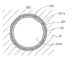
- the column joint structure 10b is formed by the lower base cap 5 and the upper fourth column 2a with the lower shelf 3c interposed therebetween.
- the five support joint structures 10a and the five support joint structures 10b are all the same structure, only one support joint structure 10a and one support joint structure 10b will be described.
- the third strut 1a which is the same as the first strut 1, is fitted on the opposite side of the second strut 2 of the strut joint structure 10 (in the direction of reference sign U in FIG. 9).
- the fitting posture of the third column 1a is the same as the posture of the first column 1 depicted in FIG. 1, and the third fitting portion 13a of the third column 1a is fitted into the through hole of the upper shelf 3a. It is. Since the 3rd fitting part 13a is the same as the 1st fitting part 13, the description is abbreviate
- the through hole of the shelf plate 3a and the third fitting portion 13a of the third support column 1a are fitted together with the first through hole 31 of the shelf plate 3 and the first support column 1 of the first support column 1a. Since it is the same as the fitting with the fitting part 13, the description is abbreviate
- a cap 4 as shown in FIG. 11 is fitted into the end of the third fitting portion 13a of the third column 1a fitted into the shelf plate 3a.
- the cap 4 is a pipe in which fourth vertical ribs (fourth unevenness) 411 are formed on the outer peripheral surface having an outer diameter smaller than the outer diameter of the cap top plate 42 and the cap top plate 42 extending downward from the back surface of the cap top plate 42.
- the 4th fitting part 41 of the cap 4 is the same as the 2nd fitting part 23 of the 2nd support
- the cap 4 is fitted by pushing the fourth fitting portion 41 of the cap 4 into the third fitting portion 13a of the third support column 1a by hand until the cap top plate 42 comes into contact with the shelf plate 3a.
- the inner diameter of the third fitting portion 13 a of the third support column 1 a and the outer diameter of the fourth fitting portion 41 of the cap 4 are larger in the dimension difference zero or the outer diameter of the fourth fitting portion 41 of the cap 4.
- the fourth vertical rib 411 of the fourth fitting portion 41 of the cap 4 is slightly elastically deformed by being pushed firmly by hand, and the fourth fitting portion 41 is the third fitting portion 13a of the third support column 1a. (FIGS. 10 to 12).
- the fourth strut 2a which is the same as the second strut 1, is fitted on the non-fitting side of the first strut 1 of the strut joint structure 10 (in the direction of symbol B in FIG. 13).
- the fitting posture of the fourth column 2a is the same as the posture of the second column 2 depicted in FIG. That is, in the column joint structure 10b, the base cap 5 is fitted into the through hole of the lower shelf 3c from the back side of the lower shelf 3c, and then into the fifth fitting portion 52 of the base cap 5.
- the sixth fitting portion 23a of the fourth support column 2a is press-fitted.
- the base cap 5 abuts against an installation surface such as a floor and protects the end of the sixth fitting portion 23a of the fourth support column 2a.
- the base cap 5 is fitted as shown in FIG.
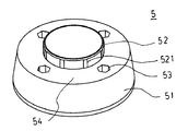
- the base cap 5 has a pipe-like shape in which fifth vertical ribs (fifth unevenness) 521 are formed on an outer peripheral surface having an outer diameter smaller than the outer diameter of the base 51 and the base 51 extending upward from the upper surface of the base 51.
- a fifth fitting portion 52 is provided.
- the fifth fitting portion 52 of the base cap 5 is the same as the first fitting portion 13 of the first strut 1 in the strut joint structure 10, and the description thereof is omitted.
- the base 51 is a disk-shaped object composed of a bottom surface in contact with the installation surface and a top surface 54 of a circumferential portion excluding the central portion. Moreover, the inside of the base 51 is made into a rib structure to achieve weight reduction and high strength.
- the base 51 is formed with four bolt implantation holes 53 into which caster mounting bolts, which are optional components, are inserted.
- the fitting of the base cap 5 to the shelf 3c is the same method and the same action as the fitting of the first fitting portion 13 of the first support 1 to the shelf 3 in the support joint structure 10, and the description thereof is omitted. To do.
- the sixth fitting portion 23a of the fourth support column 2a is strongly pushed by hand into the fifth fitting portion 52 of the base cap 5 until the fourth flange portion 22a contacts the shelf plate 3c.
- the inner diameter of the fifth fitting portion 52 of the base cap 5 and the outer diameter of the sixth fitting portion 23a of the fourth support column 2a are either zero or the outer diameter of the sixth fitting portion 23a of the fourth support column 2a. Since it is large, the fifth vertical rib 521 of the sixth fitting portion 23a of the fourth support column 2a is slightly elastically deformed by being pushed in by hand, and the sixth fitting portion 23a of the fourth support column 2a is based on the base.
- the cap 5 is fitted into the fifth fitting portion 52 (FIGS. 14 to 16).
- the fourth flange 22a of the fourth support column 2a and the top surface 54 of the base 51 of the base cap 5 cooperate to sandwich the shelf plate 3c. The backlash of 5 disappears.
- the strut joint structure 10 of the present invention is not limited to the above embodiment, and various modifications can be made. That is, the first unevenness, the second unevenness, and the unevenness in the column joint structures 10, 10a and 10b are not limited to those in which the vertical ribs are formed on the outer peripheral surface. For example, the horizontal ribs are formed on the outer peripheral surface. And those in which mixed ribs of vertical ribs and horizontal ribs are formed, and those in which a large number of protrusions are formed. When the first unevenness, the second unevenness, and the unevenness are a large number of protrusions, the protrusions are formed on the entire outer peripheral surface at an arbitrary or equal pitch.
- the heights of the first unevenness, the second unevenness, and the unevenness illustrated are the same as the height of the vertical rib.
- the arrangement of the first column and the second column with respect to the shelf plate 3 is not limited to the above embodiment.
- the first column 1 is above the shelf plate 3, and the second column 2 is the shelf plate. 3 may be located below.
- the shape of the first column main body 11 of the first column 1 on the anti-fitting side and the shape of the second column 2 of the second column main body 21 on the counter-fitting side are as described above.
- pillar 1 is made into the fitting structure similar to the 2nd fitting part 23 of the 2nd support
- the cross-sectional shape of the first column main body 11 of the first column 1 and the cross-sectional shape of the second column main body 21 of the second column 2 are limited to the quadrangle of the above embodiment. It may not be circular or elliptical.
- the mounting surface of the main body portion of the shelf board 3 is not limited to a flat surface, and may be formed with a partition groove, an engagement hole, or the like according to the purpose of use.
- a shape of the 1st collar part 12 and the 2nd collar part 22 a disk shape, flat shape, etc. are mentioned other than the above.
- the first fitting portion 13 of the first column 1, the third fitting portion 13 a of the third column 1 a, and the fitting portion 52 of the base cap 5 are arranged at the tip (second column).
- a notch extending to the middle in the longitudinal direction may be formed on the fitting side). Two notches are convenient for every 180 degrees in the circumferential direction of the pipe or four for every 90 degrees. Thereby, when pushing the 1st support
- the flat table 20 of the present invention is not limited to the above embodiment, and various modifications can be made. That is, the flat table 20 may have one, two, or four or more stages in addition to the three stages. Moreover, in a shelf board with a particularly large mounting area, six or more strut joint structures 10 may be used. In the case of a one-stage flat base, any of the column joint structures 10, 10a, 10b can be applied. In the one-stage flat base using the column joint structure 10, the lower end of the first column is installed on the installation surface as it is, and the installation of the shelf board is omitted at the upper end of the second column. In the one-stage flat base using the column joint structure 10a, the lower end of the column is directly installed on the installation surface. In the one-stage flat base using the column joint structure 10b, the installation of the shelf board is omitted at the upper end of the upper column.
- any one of a combination of the column joint structure 10 and the column joint structure 10a, a combination of the column joint structure 10 and the column joint structure 10b, and a combination of the column joint structure 10a and the column joint structure 10b is also applicable.
- the outer peripheral surface of the first fitting portion and the outer peripheral surface of the second fitting portion are uneven.
- the inner periphery of the first fitting portion is not limited to the one that does not form unevenness, and the outer periphery of the second fitting portion is formed with unevenness on the outer peripheral surface and inner peripheral surface of the first fitting portion.
- the surface may not be uneven. Even if it is such a fitting form, there exists an effect similar to a 1st embodiment.
- the outer peripheral surface of the fitting part of the support column and the fitting part of the cap are uneven. It is not limited to the one that does not form irregularities on the inner peripheral surface of the fitting part of the support column, but is formed with irregularities such as vertical ribs on the outer peripheral surface and inner peripheral surface of the fitting part of the support column.
- the outer peripheral surface of the fitting portion may not be uneven. Even if it is such a fitting form, there exists an effect similar to 2nd Embodiment.
- the outer peripheral surface of the fitting part of the support column and the fitting part of the base cap are as follows. Forming irregularities, not limited to those that do not form irregularities on the inner peripheral surface of the fitting portion of the column, forming irregularities such as vertical ribs on the outer peripheral surface and inner peripheral surface of the fitting portion of the column, The outer peripheral surface of the fitting portion of the base cap may not be uneven. Even if it is such a fitting form, there exists an effect similar to a 3rd embodiment.
- the strut joint structure of the present invention has a simple structure and includes three members: a first strut, a second strut, and a shelf board; three members, a strut, a cap, and a shelf board; and three members, a strut, a base cap, and a shelf board.
- the fitting is performed by press-fitting and one surface of the fitting is an uneven surface, a strong fitting strength and a fitting without backlash can be obtained.
- the flat base of the present invention can be assembled only by fitting by fitting between pipes without using metals such as pins and bolts, and can reduce the cost and labor of the assembly process. It is easy to change.
- a flat base uses a support
Landscapes
- Engineering & Computer Science (AREA)
- General Engineering & Computer Science (AREA)
- Mechanical Engineering (AREA)
- Assembled Shelves (AREA)
- Display Racks (AREA)
Abstract
L'invention concerne une structure de ferrure d'assemblage de montant qui est équipée : d'un premier montant (1) qui possède une première partie ajustement (13) tubulaire sur laquelle sont formés une première partie rebord (12) qui se prolonge depuis la face périphérique externe d'une première partie corps principal de montant (11) tubulaire vers le côté externe, et des premiers creux et reliefs (131) sur la face périphérique externe se prolongeant côté extrémité avant; d'un second montant (2) qui possède une seconde partie ajustement (23) tubulaire sur laquelle sont formés une seconde partie rebord (22) qui se prolonge depuis la face périphérique externe d'une seconde partie corps principal de montant (21) tubulaire vers le côté externe, et des seconds creux et reliefs (231) sur la face périphérique externe se prolongeant côté extrémité avant; et d'une tablette d'étagère (3) qui possède un trou débouchant (31) dans lequel la première partie ajustement (13) s'ajuste par pression. La première partie ajustement (13) est ajustée par pression dans le trou débouchant (31) de la tablette d'étagère (3), la seconde partie ajustement (23) est ajustée par pression dans la première partie ajustement (13), et la tablette d'étagère (3) est enserrée entre la première partie rebord (12) et la seconde partie rebord (22). Ainsi, une ferrure d'assemblage de montant sans jeu est obtenue par simple assemblage par pression de tubes entre eux, sans mise en œuvre de broche ou boulon.
Priority Applications (1)
| Application Number | Priority Date | Filing Date | Title |
|---|---|---|---|
| JP2012554862A JP5971760B2 (ja) | 2011-01-27 | 2012-01-27 | 支柱継手構造体及びこれを用いた平台 |
Applications Claiming Priority (2)
| Application Number | Priority Date | Filing Date | Title |
|---|---|---|---|
| JP2011015151 | 2011-01-27 | ||
| JP2011-015151 | 2011-01-27 |
Publications (1)
| Publication Number | Publication Date |
|---|---|
| WO2012102376A1 true WO2012102376A1 (fr) | 2012-08-02 |
Family
ID=46580939
Family Applications (1)
| Application Number | Title | Priority Date | Filing Date |
|---|---|---|---|
| PCT/JP2012/051792 Ceased WO2012102376A1 (fr) | 2011-01-27 | 2012-01-27 | Structure de ferrure d'assemblage de montant, et base plate équipée de celle-ci |
Country Status (2)
| Country | Link |
|---|---|
| JP (1) | JP5971760B2 (fr) |
| WO (1) | WO2012102376A1 (fr) |
Cited By (2)
| Publication number | Priority date | Publication date | Assignee | Title |
|---|---|---|---|---|
| KR101742202B1 (ko) * | 2016-05-16 | 2017-06-09 | 주식회사 녹스기어 | 개선된 트레이 결합구조를 갖는 다용도 접이식 거치대 |
| WO2019237206A1 (fr) * | 2018-06-15 | 2019-12-19 | Cecol Domenic | Ensemble cadre modulaire |
Families Citing this family (1)
| Publication number | Priority date | Publication date | Assignee | Title |
|---|---|---|---|---|
| JP5903140B1 (ja) * | 2014-09-04 | 2016-04-13 | 株式会社サンカ | 組立式収納体 |
Citations (5)
| Publication number | Priority date | Publication date | Assignee | Title |
|---|---|---|---|---|
| JPS6315827U (fr) * | 1986-07-15 | 1988-02-02 | ||
| JPH0326233U (fr) * | 1989-07-17 | 1991-03-18 | ||
| JPH0641547U (ja) * | 1992-11-20 | 1994-06-03 | 株式会社ヨシカワ | 天板用トレー |
| JPH0641546U (ja) * | 1992-11-20 | 1994-06-03 | 株式会社ヨシカワ | 収納棚 |
| JP2003148425A (ja) * | 2001-11-12 | 2003-05-21 | Araya Industrial Co Ltd | 環状管体並びに手摺及び組立棚 |
Family Cites Families (1)
| Publication number | Priority date | Publication date | Assignee | Title |
|---|---|---|---|---|
| JP3026233U (ja) * | 1995-12-22 | 1996-07-02 | 株式会社伸和 | 連結部材の嵌合装置およびその装置を具備する家具 |
-
2012
- 2012-01-27 WO PCT/JP2012/051792 patent/WO2012102376A1/fr not_active Ceased
- 2012-01-27 JP JP2012554862A patent/JP5971760B2/ja active Active
Patent Citations (5)
| Publication number | Priority date | Publication date | Assignee | Title |
|---|---|---|---|---|
| JPS6315827U (fr) * | 1986-07-15 | 1988-02-02 | ||
| JPH0326233U (fr) * | 1989-07-17 | 1991-03-18 | ||
| JPH0641547U (ja) * | 1992-11-20 | 1994-06-03 | 株式会社ヨシカワ | 天板用トレー |
| JPH0641546U (ja) * | 1992-11-20 | 1994-06-03 | 株式会社ヨシカワ | 収納棚 |
| JP2003148425A (ja) * | 2001-11-12 | 2003-05-21 | Araya Industrial Co Ltd | 環状管体並びに手摺及び組立棚 |
Cited By (2)
| Publication number | Priority date | Publication date | Assignee | Title |
|---|---|---|---|---|
| KR101742202B1 (ko) * | 2016-05-16 | 2017-06-09 | 주식회사 녹스기어 | 개선된 트레이 결합구조를 갖는 다용도 접이식 거치대 |
| WO2019237206A1 (fr) * | 2018-06-15 | 2019-12-19 | Cecol Domenic | Ensemble cadre modulaire |
Also Published As
| Publication number | Publication date |
|---|---|
| JP5971760B2 (ja) | 2016-08-17 |
| JPWO2012102376A1 (ja) | 2014-06-30 |
Similar Documents
| Publication | Publication Date | Title |
|---|---|---|
| JP5522750B2 (ja) | カップリング部材及びそれを備えた組立棚 | |
| CN105025753B (zh) | 联接构件及使用该联接构件的组装架 | |
| KR20180113546A (ko) | 3개의 패널-형상 요소들의 세트 | |
| JP5971760B2 (ja) | 支柱継手構造体及びこれを用いた平台 | |
| JP6096521B2 (ja) | フローティングナットおよびフローティングボルト | |
| JP4518434B2 (ja) | 組立棚 | |
| CN211039323U (zh) | 组装装置的快速连接结构 | |
| CN115067666B (zh) | 一种桌子 | |
| CN110848224B (zh) | 一种汽车内饰件螺丝连接装置 | |
| KR101487734B1 (ko) | 가구 조립체 | |
| CN222362585U (zh) | 挂墙马桶的快装结构 | |
| CN211599221U (zh) | 包装螺栓组件及洗衣机 | |
| KR200268616Y1 (ko) | 장식장 연결부재 | |
| JP2010233769A (ja) | 組立棚 | |
| KR200498464Y1 (ko) | 매트리스 지지대 및 이를 구비하는 침대 프레임 | |
| CN103438063B (zh) | 管件结构 | |
| CN220545969U (zh) | 可快速拆装桌子 | |
| JP5513161B2 (ja) | 陳列棚 | |
| CN210599719U (zh) | 一种锁扣装置 | |
| KR101468914B1 (ko) | 돌기형 비드와 외측홈을 구비한 팬너트 | |
| KR102220557B1 (ko) | 지지다리 조립용 연결구 | |
| JP6954758B2 (ja) | 床パネル固定具 | |
| KR101557001B1 (ko) | 조립식 가구 | |
| CA2503940A1 (fr) | Systeme de rayonnage | |
| JPH0226341Y2 (fr) |
Legal Events
| Date | Code | Title | Description |
|---|---|---|---|
| 121 | Ep: the epo has been informed by wipo that ep was designated in this application |
Ref document number: 12738966 Country of ref document: EP Kind code of ref document: A1 |
|
| ENP | Entry into the national phase |
Ref document number: 2012554862 Country of ref document: JP Kind code of ref document: A |
|
| NENP | Non-entry into the national phase |
Ref country code: DE |
|
| 122 | Ep: pct application non-entry in european phase |
Ref document number: 12738966 Country of ref document: EP Kind code of ref document: A1 |