WO2012102378A1 - Ensemble carbure de silicium, tube de transfert de chaleur comprenant celui-ci et échangeur de chaleur équipé du tube de transfert de chaleur - Google Patents
Ensemble carbure de silicium, tube de transfert de chaleur comprenant celui-ci et échangeur de chaleur équipé du tube de transfert de chaleur Download PDFInfo
- Publication number
- WO2012102378A1 WO2012102378A1 PCT/JP2012/051807 JP2012051807W WO2012102378A1 WO 2012102378 A1 WO2012102378 A1 WO 2012102378A1 JP 2012051807 W JP2012051807 W JP 2012051807W WO 2012102378 A1 WO2012102378 A1 WO 2012102378A1
- Authority
- WO
- WIPO (PCT)
- Prior art keywords
- silicon carbide
- carbide based
- transfer tube
- void diameter
- heat transfer
- Prior art date
- Legal status (The legal status is an assumption and is not a legal conclusion. Google has not performed a legal analysis and makes no representation as to the accuracy of the status listed.)
- Ceased
Links
Images


Classifications
-
- F—MECHANICAL ENGINEERING; LIGHTING; HEATING; WEAPONS; BLASTING
- F28—HEAT EXCHANGE IN GENERAL
- F28F—DETAILS OF HEAT-EXCHANGE AND HEAT-TRANSFER APPARATUS, OF GENERAL APPLICATION
- F28F21/00—Constructions of heat-exchange apparatus characterised by the selection of particular materials
- F28F21/04—Constructions of heat-exchange apparatus characterised by the selection of particular materials of ceramic; of concrete; of natural stone
-
- C—CHEMISTRY; METALLURGY
- C04—CEMENTS; CONCRETE; ARTIFICIAL STONE; CERAMICS; REFRACTORIES
- C04B—LIME, MAGNESIA; SLAG; CEMENTS; COMPOSITIONS THEREOF, e.g. MORTARS, CONCRETE OR LIKE BUILDING MATERIALS; ARTIFICIAL STONE; CERAMICS; REFRACTORIES; TREATMENT OF NATURAL STONE
- C04B35/00—Shaped ceramic products characterised by their composition; Ceramics compositions; Processing powders of inorganic compounds preparatory to the manufacturing of ceramic products
- C04B35/515—Shaped ceramic products characterised by their composition; Ceramics compositions; Processing powders of inorganic compounds preparatory to the manufacturing of ceramic products based on non-oxide ceramics
- C04B35/56—Shaped ceramic products characterised by their composition; Ceramics compositions; Processing powders of inorganic compounds preparatory to the manufacturing of ceramic products based on non-oxide ceramics based on carbides or oxycarbides
- C04B35/565—Shaped ceramic products characterised by their composition; Ceramics compositions; Processing powders of inorganic compounds preparatory to the manufacturing of ceramic products based on non-oxide ceramics based on carbides or oxycarbides based on silicon carbide
- C04B35/575—Shaped ceramic products characterised by their composition; Ceramics compositions; Processing powders of inorganic compounds preparatory to the manufacturing of ceramic products based on non-oxide ceramics based on carbides or oxycarbides based on silicon carbide obtained by pressure sintering
-
- C—CHEMISTRY; METALLURGY
- C04—CEMENTS; CONCRETE; ARTIFICIAL STONE; CERAMICS; REFRACTORIES
- C04B—LIME, MAGNESIA; SLAG; CEMENTS; COMPOSITIONS THEREOF, e.g. MORTARS, CONCRETE OR LIKE BUILDING MATERIALS; ARTIFICIAL STONE; CERAMICS; REFRACTORIES; TREATMENT OF NATURAL STONE
- C04B37/00—Joining burned ceramic articles with other burned ceramic articles or other articles by heating
- C04B37/001—Joining burned ceramic articles with other burned ceramic articles or other articles by heating directly with other burned ceramic articles
-
- C—CHEMISTRY; METALLURGY
- C04—CEMENTS; CONCRETE; ARTIFICIAL STONE; CERAMICS; REFRACTORIES
- C04B—LIME, MAGNESIA; SLAG; CEMENTS; COMPOSITIONS THEREOF, e.g. MORTARS, CONCRETE OR LIKE BUILDING MATERIALS; ARTIFICIAL STONE; CERAMICS; REFRACTORIES; TREATMENT OF NATURAL STONE
- C04B37/00—Joining burned ceramic articles with other burned ceramic articles or other articles by heating
- C04B37/003—Joining burned ceramic articles with other burned ceramic articles or other articles by heating by means of an interlayer consisting of a combination of materials selected from glass, or ceramic material with metals, metal oxides or metal salts
- C04B37/005—Joining burned ceramic articles with other burned ceramic articles or other articles by heating by means of an interlayer consisting of a combination of materials selected from glass, or ceramic material with metals, metal oxides or metal salts consisting of glass or ceramic material
-
- C—CHEMISTRY; METALLURGY
- C04—CEMENTS; CONCRETE; ARTIFICIAL STONE; CERAMICS; REFRACTORIES
- C04B—LIME, MAGNESIA; SLAG; CEMENTS; COMPOSITIONS THEREOF, e.g. MORTARS, CONCRETE OR LIKE BUILDING MATERIALS; ARTIFICIAL STONE; CERAMICS; REFRACTORIES; TREATMENT OF NATURAL STONE
- C04B2235/00—Aspects relating to ceramic starting mixtures or sintered ceramic products
- C04B2235/02—Composition of constituents of the starting material or of secondary phases of the final product
- C04B2235/30—Constituents and secondary phases not being of a fibrous nature
- C04B2235/38—Non-oxide ceramic constituents or additives
- C04B2235/3817—Carbides
- C04B2235/3821—Boron carbides
-
- C—CHEMISTRY; METALLURGY
- C04—CEMENTS; CONCRETE; ARTIFICIAL STONE; CERAMICS; REFRACTORIES
- C04B—LIME, MAGNESIA; SLAG; CEMENTS; COMPOSITIONS THEREOF, e.g. MORTARS, CONCRETE OR LIKE BUILDING MATERIALS; ARTIFICIAL STONE; CERAMICS; REFRACTORIES; TREATMENT OF NATURAL STONE
- C04B2235/00—Aspects relating to ceramic starting mixtures or sintered ceramic products
- C04B2235/02—Composition of constituents of the starting material or of secondary phases of the final product
- C04B2235/30—Constituents and secondary phases not being of a fibrous nature
- C04B2235/42—Non metallic elements added as constituents or additives, e.g. sulfur, phosphor, selenium or tellurium
- C04B2235/422—Carbon
- C04B2235/425—Graphite
-
- C—CHEMISTRY; METALLURGY
- C04—CEMENTS; CONCRETE; ARTIFICIAL STONE; CERAMICS; REFRACTORIES
- C04B—LIME, MAGNESIA; SLAG; CEMENTS; COMPOSITIONS THEREOF, e.g. MORTARS, CONCRETE OR LIKE BUILDING MATERIALS; ARTIFICIAL STONE; CERAMICS; REFRACTORIES; TREATMENT OF NATURAL STONE
- C04B2235/00—Aspects relating to ceramic starting mixtures or sintered ceramic products
- C04B2235/02—Composition of constituents of the starting material or of secondary phases of the final product
- C04B2235/50—Constituents or additives of the starting mixture chosen for their shape or used because of their shape or their physical appearance
- C04B2235/54—Particle size related information
- C04B2235/5418—Particle size related information expressed by the size of the particles or aggregates thereof
- C04B2235/5436—Particle size related information expressed by the size of the particles or aggregates thereof micrometer sized, i.e. from 1 to 100 micron
-
- C—CHEMISTRY; METALLURGY
- C04—CEMENTS; CONCRETE; ARTIFICIAL STONE; CERAMICS; REFRACTORIES
- C04B—LIME, MAGNESIA; SLAG; CEMENTS; COMPOSITIONS THEREOF, e.g. MORTARS, CONCRETE OR LIKE BUILDING MATERIALS; ARTIFICIAL STONE; CERAMICS; REFRACTORIES; TREATMENT OF NATURAL STONE
- C04B2235/00—Aspects relating to ceramic starting mixtures or sintered ceramic products
- C04B2235/02—Composition of constituents of the starting material or of secondary phases of the final product
- C04B2235/50—Constituents or additives of the starting mixture chosen for their shape or used because of their shape or their physical appearance
- C04B2235/54—Particle size related information
- C04B2235/5418—Particle size related information expressed by the size of the particles or aggregates thereof
- C04B2235/5445—Particle size related information expressed by the size of the particles or aggregates thereof submicron sized, i.e. from 0,1 to 1 micron
-
- C—CHEMISTRY; METALLURGY
- C04—CEMENTS; CONCRETE; ARTIFICIAL STONE; CERAMICS; REFRACTORIES
- C04B—LIME, MAGNESIA; SLAG; CEMENTS; COMPOSITIONS THEREOF, e.g. MORTARS, CONCRETE OR LIKE BUILDING MATERIALS; ARTIFICIAL STONE; CERAMICS; REFRACTORIES; TREATMENT OF NATURAL STONE
- C04B2235/00—Aspects relating to ceramic starting mixtures or sintered ceramic products
- C04B2235/02—Composition of constituents of the starting material or of secondary phases of the final product
- C04B2235/50—Constituents or additives of the starting mixture chosen for their shape or used because of their shape or their physical appearance
- C04B2235/54—Particle size related information
- C04B2235/5463—Particle size distributions
- C04B2235/5472—Bimodal, multi-modal or multi-fraction
-
- C—CHEMISTRY; METALLURGY
- C04—CEMENTS; CONCRETE; ARTIFICIAL STONE; CERAMICS; REFRACTORIES
- C04B—LIME, MAGNESIA; SLAG; CEMENTS; COMPOSITIONS THEREOF, e.g. MORTARS, CONCRETE OR LIKE BUILDING MATERIALS; ARTIFICIAL STONE; CERAMICS; REFRACTORIES; TREATMENT OF NATURAL STONE
- C04B2235/00—Aspects relating to ceramic starting mixtures or sintered ceramic products
- C04B2235/70—Aspects relating to sintered or melt-casted ceramic products
- C04B2235/95—Products characterised by their size, e.g. microceramics
-
- C—CHEMISTRY; METALLURGY
- C04—CEMENTS; CONCRETE; ARTIFICIAL STONE; CERAMICS; REFRACTORIES
- C04B—LIME, MAGNESIA; SLAG; CEMENTS; COMPOSITIONS THEREOF, e.g. MORTARS, CONCRETE OR LIKE BUILDING MATERIALS; ARTIFICIAL STONE; CERAMICS; REFRACTORIES; TREATMENT OF NATURAL STONE
- C04B2235/00—Aspects relating to ceramic starting mixtures or sintered ceramic products
- C04B2235/70—Aspects relating to sintered or melt-casted ceramic products
- C04B2235/96—Properties of ceramic products, e.g. mechanical properties such as strength, toughness, wear resistance
- C04B2235/963—Surface properties, e.g. surface roughness
-
- C—CHEMISTRY; METALLURGY
- C04—CEMENTS; CONCRETE; ARTIFICIAL STONE; CERAMICS; REFRACTORIES
- C04B—LIME, MAGNESIA; SLAG; CEMENTS; COMPOSITIONS THEREOF, e.g. MORTARS, CONCRETE OR LIKE BUILDING MATERIALS; ARTIFICIAL STONE; CERAMICS; REFRACTORIES; TREATMENT OF NATURAL STONE
- C04B2237/00—Aspects relating to ceramic laminates or to joining of ceramic articles with other articles by heating
- C04B2237/02—Aspects relating to interlayers, e.g. used to join ceramic articles with other articles by heating
- C04B2237/04—Ceramic interlayers
- C04B2237/08—Non-oxidic interlayers
- C04B2237/083—Carbide interlayers, e.g. silicon carbide interlayers
-
- C—CHEMISTRY; METALLURGY
- C04—CEMENTS; CONCRETE; ARTIFICIAL STONE; CERAMICS; REFRACTORIES
- C04B—LIME, MAGNESIA; SLAG; CEMENTS; COMPOSITIONS THEREOF, e.g. MORTARS, CONCRETE OR LIKE BUILDING MATERIALS; ARTIFICIAL STONE; CERAMICS; REFRACTORIES; TREATMENT OF NATURAL STONE
- C04B2237/00—Aspects relating to ceramic laminates or to joining of ceramic articles with other articles by heating
- C04B2237/30—Composition of layers of ceramic laminates or of ceramic or metallic articles to be joined by heating, e.g. Si substrates
- C04B2237/32—Ceramic
- C04B2237/36—Non-oxidic
- C04B2237/365—Silicon carbide
-
- C—CHEMISTRY; METALLURGY
- C04—CEMENTS; CONCRETE; ARTIFICIAL STONE; CERAMICS; REFRACTORIES
- C04B—LIME, MAGNESIA; SLAG; CEMENTS; COMPOSITIONS THEREOF, e.g. MORTARS, CONCRETE OR LIKE BUILDING MATERIALS; ARTIFICIAL STONE; CERAMICS; REFRACTORIES; TREATMENT OF NATURAL STONE
- C04B2237/00—Aspects relating to ceramic laminates or to joining of ceramic articles with other articles by heating
- C04B2237/50—Processing aspects relating to ceramic laminates or to the joining of ceramic articles with other articles by heating
- C04B2237/76—Forming laminates or joined articles comprising at least one member in the form other than a sheet or disc, e.g. two tubes or a tube and a sheet or disc
- C04B2237/765—Forming laminates or joined articles comprising at least one member in the form other than a sheet or disc, e.g. two tubes or a tube and a sheet or disc at least one member being a tube
Definitions
- the present invention relates to a silicon carbide based joined body formed by joining silicon carbide based members, a heat transfer tube made of the same, and a heat exchanger provided with the heat transfer tube.
- Silicon carbide is used in a wide range of fields because of its high mechanical strength and excellent properties such as heat resistance and corrosion resistance.
- large-scale equipment and complicated processing are required, and it has been difficult to integrally form a molded body having a large size, a long length, or a complicated shape.
- a molded body can be obtained, it is difficult to obtain a sintered body without defects because the ceramic itself is a material that is difficult to fire. For this reason, by joining a plurality of sintered bodies to form a joined body, it is possible to cope with an increase in the size, lengthening, and shape of the member.
- a silicon carbide joined body in which a first silicon carbide sintered body and a second silicon carbide sintered body are joined via a joining layer made of metallic silicon.
- the first silicon carbide based sintered body has a bonding surface on which the metal silicon layer is formed
- the second silicon carbide sintered body has a bonding surface that comes into contact with the metal silicon layer.
- Each bonded surface of the first and second silicon carbide sintered bodies has a surface roughness Ra of 0.6 ⁇ m or less, and a silicon carbide bonded body bonded via a bonding layer obtained by heat-treating a metal silicon layer.
- the silicon carbide bonded body described in Patent Document 1 is described as having a four-point bending strength of 250 MPa or more and a maximum of 284 MPa in accordance with JIS R 1624, which describes a bending strength test method for bonded ceramics.
- JIS R 1624 describes a bending strength test method for bonded ceramics.
- a joined body is used as a heat transfer tube serving as a flow path for a medium provided in a heat exchanger, it must be firmly joined even in a high temperature environment exceeding 1500 ° C.
- the present invention has been devised to solve the above problems, and provides a silicon carbide based joined body having high joining strength in a high temperature environment, a heat transfer tube using the same, and a heat exchanger equipped with the heat transfer tube. It is intended to do.
- the silicon carbide based joined body of the present invention is formed by joining silicon carbide based members formed of a sintered body mainly composed of silicon carbide to each other through a joined member formed of a sintered body mainly composed of silicon carbide.
- the maximum void diameter of the bonding member is smaller than the maximum void diameter of the silicon carbide member.
- the heat transfer tube of the present invention is characterized by comprising the silicon carbide joined body of the present invention having the above-described configuration.
- the heat exchanger of the present invention is characterized by including the heat transfer tube of the present invention having the above-described configuration.
- the joining member since the maximum void diameter of the joining member is smaller than the maximum void diameter of the silicon carbide based member, the joining member is less likely to generate cracks and cracks.
- the bonding member itself has a high mechanical strength, can withstand bending stress when a load is applied to the bonding member interposed between the silicon carbide members, and has a high bonding strength. It can be set as a joined body.
- the heat transfer tube of the present invention since it is composed of the silicon carbide based bonded body of the present invention, it is possible to maintain a strong bond even in a high temperature environment and to have excellent thermal conductivity. It can be suitably used for a heat transfer tube that transfers heat from the outside and warms the medium circulating inside, or distributes a high-temperature medium inside.
- silicon carbide members having high mechanical strength and excellent heat resistance and corrosion resistance are bonded to each other, and the transmission of the present invention is formed of a silicon carbide bonded body having high bonding strength. Since the heat pipe is provided, a highly reliable heat exchanger that can be used stably over a long period of time can be obtained.
- silicon carbide based members formed of a sintered body containing silicon carbide as a main component are joined to each other via a bonded member formed of a sintered body containing silicon carbide as a main component.
- the maximum void diameter of the bonding member is smaller than the maximum void diameter of the silicon carbide member.
- a sintered body mainly composed of silicon carbide is simply referred to as a silicon carbide based sintered body.
- the main component here is a component that occupies 80% by mass or more with respect to 100% by mass of all components constituting the silicon carbide member and the joining member, and preferably 90% by mass or more. More preferably, it is 95% by mass or more.
- the silicon carbide based joined body of the present embodiment is composed of a silicon carbide based member formed of a silicon carbide based sintered body and a joining member.
- the silicon carbide based joined body of the present embodiment is joined to the silicon carbide based joined body. What is necessary is just to perform discrimination with a member with the following method. As a specific example, using a scanning electron microscope (SEM), in the range of magnifications of 150 times or more and 1000 times or less, a magnification capable of discriminating the bonding interface is appropriately selected, and the surface of the silicon carbide based bonded body is observed. Find the interface and calculate the maximum void diameter of one and the other with the joint interface as the boundary.
- SEM scanning electron microscope
- the thickness of the joining portion is thin, it is not an exaggeration to say that it can also be determined by the interval between the joining interfaces, and the portion corresponding to the portion where the spacing between the joining interfaces is short is the joining member. is there.
- the maximum void diameter for example, using a diamond abrasive having an average particle diameter of 0.05 to 0.15 ⁇ m and a lapping machine made of tin, silicon carbide containing one and the other at the joining interface as a boundary
- the joined body is polished until the arithmetic average roughness Ra becomes 0.2 ⁇ m or less to obtain an observation surface.
- images were taken at 5 magnifications (one field of view was 300 ⁇ m ⁇ 200 ⁇ m) from one and the other observation surfaces at 400 ⁇ magnification with the bonding interface as the boundary.
- the void diameter is measured using analysis software “A image-kun” (registered trademark, manufactured by Asahi Kasei Engineering Co., Ltd.).
- the field of view is selected except where it contains abnormally large voids that are not observed in other fields of view.
- a cumulative distribution curve is created using the obtained void diameter, and the void diameter corresponding to 90% when the area of the cumulative distribution curve is 100% is taken as the maximum void diameter, and this value is compared.
- the silicon carbide member and the joining member in this embodiment are discriminated.
- the joining member since the maximum void diameter of the joining member is smaller than the maximum void diameter of the silicon carbide based member, the joining member is less likely to generate cracks and cracks as starting points.
- the joining member itself has high mechanical strength. Therefore, it is possible to withstand bending stress when a load is applied to the bonding member interposed between the silicon carbide based members, so that a silicon carbide based bonded body having high bonding strength can be obtained. This is because, when trying to increase the bending strength of the joining member of the silicon carbide based joined body, it is strongly bonded at the joining interface at both ends of the joining member, as well as compressive stress on the load side due to the applied load. However, since tensile stress acts on the opposite side, it is based on the knowledge that the maximum void diameter on the surface of the joining member affects.
- this joint strength represents using the value of 4-point bending strength measured based on JISR 1624-2010.
- a test piece it produces so that a joining member may be located in the center part of a test piece.
- the value of the four-point bending strength shown in the present embodiment is that the cross-section is 4 mm ⁇ 3 mm, the length is 38 mm (a joining member having a length of 6 mm is interposed between the silicon carbide members each having a length of 16 mm). It was measured using a silicon carbide joined body with a chamfered surface as a test piece.
- the silicon carbide based joined body of the present embodiment since the silicon carbide based member and the joining member are both formed of a silicon carbide based sintered body, the thermal expansion difference between the silicon carbide based member and the joining member. Therefore, even when used in a high temperature environment, the stress due to the difference in thermal expansion is small, and excellent bonding strength can be maintained. In addition, since both the silicon carbide member and the joining member are formed of a silicon carbide sintered body, heat transfer is rarely hindered, and thus excellent heat transfer characteristics are obtained.
- the maximum void diameter of the silicon carbide based member is 30 ⁇ m or less.
- the silicon carbide member itself has a high mechanical strength because there are few cracks and occurrence of cracks as starting points of cracks.
- the contact area on the joint surface with the joint member can be increased, so that the joint strength can be increased.
- the lower limit of the maximum void diameter is about 3 ⁇ m from the viewpoint of cost and difficulty in manufacturing including equipment.
- the silicon carbide sintered body has high mechanical strength and is excellent in heat resistance and corrosion resistance. Since the material members are composed and are firmly joined, it is preferable to increase the size, length and complexity of the members that require high mechanical strength, excellent heat resistance and corrosion resistance. Can be planned.
- the maximum void diameter of the bonding member is 20 ⁇ m or less.
- the average void diameter of the silicon carbide based member is 11 ⁇ m or less (excluding 0 ⁇ m).
- the silicon carbide member becomes denser, so that the silicon carbide member itself has high mechanical strength.
- the contact area on the bonding surface between the silicon carbide member and the bonding member can be increased, so that the bonding strength can be further increased.
- the average void diameter of the bonding member is 6 ⁇ m or less (excluding 0 ⁇ m).
- the image used by calculation of the maximum void diameter can be calculated
- image analysis software "A image kun” trademark, Asahi Kasei Engineering Co., Ltd. product.
- the average value of the void diameters in the respective five visual fields of the silicon carbide member and the joining member may be obtained, and a value obtained by further averaging these average values may be used as each average void diameter.
- the number of voids of the joining member is smaller than the number of voids of the silicon carbide based member.
- the number of voids can also be determined by using the image analysis software “A image-kun” (registered trademark, manufactured by Asahi Kasei Engineering Co., Ltd.) for the image used for calculating the maximum void diameter.
- the voids included in the silicon carbide based member include those oriented along a direction perpendicular to the bonding surface.
- the silicon carbide based bonded body is, for example, a cylinder and a high-temperature medium is circulated inside the cylinder, the voids included in the silicon carbide based member are perpendicular to the bonding surface. Since the turbulent flow is less likely to occur than when it is not oriented along any direction, the pressure loss is less likely to decrease.
- the voids contained in the silicon carbide member include those oriented along the direction perpendicular to the bonding surface of the silicon carbide member, observe the image used in the calculation of the maximum void diameter, What is necessary is just to certify the void in which the angle of the major axis with respect to the joint surface is within 90 ° ⁇ 10 ° as the void oriented along the direction perpendicular to the joint surface. Note that 50% or more of the observed voids are preferably oriented along the direction perpendicular to the bonding surface.
- the silicon carbide based joined body of the present embodiment when the average crystal grain size of silicon carbide in the joining member is smaller than the average crystal grain size of silicon carbide in the silicon carbide based member, it is joined more than the silicon carbide based member. Since the mechanical characteristics of the member are improved, a silicon carbide based bonded body that can withstand a larger bending stress can be obtained.
- the silicon carbide based joined body of the present embodiment when the average crystal grain size of silicon carbide in the joining member is larger than the average crystal grain size of silicon carbide in the silicon carbide based member, it is joined more than the silicon carbide based member.
- the grain boundary phase between the silicon carbide crystal grains in the member is small, and a decrease in thermal conductivity due to the interposition of the joining member can be suppressed.
- the average crystal grain size of silicon carbide in the bonded member is the average crystal size of silicon carbide in the silicon carbide based member. It is preferable that the particle size is smaller than the grain size, and when high thermal conductivity is required, the average crystal grain size of silicon carbide in the bonding member should be larger than the average crystal grain size of silicon carbide in the silicon carbide member. Is preferred.
- the average crystal grain diameter of the silicon carbide in each of a joining member and a silicon carbide-like member it carries out after etching the observation surface used for calculation of the maximum void diameter. Specifically, first, the mass ratio of each powder of sodium hydroxide and potassium nitrate is set to 1: 1, these are put in a crucible and heated to dissolve, and the observation surface is immersed in the dissolved liquid, and the processing time is set. Is etched for 1 minute or less. Then, using a scanning electron microscope, for example, images were taken from the etched surface at a magnification of 400 to 600 times (each viewing area is 300 ⁇ m ⁇ 200 ⁇ m) and intercepted. The average crystal grain size may be calculated.
- the silicon carbide based member and the joining member constituting the silicon carbide based joined body of the present embodiment contain 95% by mass or more (excluding 100% by mass) of silicon carbide.
- the silicon carbide member and the bonding member contain 95% by mass or more of silicon carbide, a silicon carbide bonded body having high mechanical strength and excellent heat resistance and corrosion resistance can be obtained.
- the Si content in the silicon carbide member and the joining member is obtained by ICP (Inductively Coupled Plasma) emission spectroscopy or fluorescent X-ray analysis, and converted to carbide (SiC). Can be obtained.
- ICP Inductively Coupled Plasma
- SiC carbide
- the silicon carbide-based member and the bonding member constituting the silicon carbide-based bonded body of this embodiment have a relative density of 95% by volume to 97% by volume and 98% by volume (excluding 100% by volume), respectively. Is preferred.
- the relative density of each of the silicon carbide based member and the joining member is determined according to JIS R 1634-1998, and the apparent density of the silicon carbide based sintered body is obtained. It may be obtained by dividing by the theoretical density.
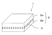
- FIG. 1 and FIG. 2 are schematic views showing a silicon carbide based joined body of the present embodiment.
- FIG. 1 shows a silicon carbide joined body 1 formed by joining rectangular silicon carbide members 2a and 2b via a joining member 3
- FIG. 2 shows cylindrical silicon carbide members 2a and 2b joined together.
- This is a silicon carbide bonded body 1 ′ formed by bonding via a bonding member 3.
- silicon carbide members 2a and 2b which are rectangular parallelepipeds formed of a silicon carbide sintered body, are joined together via a joining member 3 which is a rectangular parallelepiped formed of a silicon carbide sintered body.
- the silicon carbide based bonded body 1 of the present embodiment is a member that has high mechanical strength, excellent heat resistance and corrosion resistance, and high bonding strength not only at room temperature but also in a high temperature environment because of high bonding strength. Can be suitably increased in size.
- silicon carbide members 2a and 2b which are cylindrical bodies formed of a silicon carbide sintered body, are joined to each other via a joining member 3 which is a cylindrical body formed of a silicon carbide sintered body.
- the bonded silicon carbide based bonded body 1 ′ of the present embodiment can be firmly bonded even in a high temperature environment and has excellent thermal conductivity. It can be suitably used for a heat transfer tube that transmits and warms a medium that circulates inside, or that circulates a high-temperature medium inside. In order to configure this heat transfer tube with a joined body, the four-point bending strength at a high temperature (1500 ° C.) needs to be 200 MPa or more.
- FIG. 3 is a schematic view of a concentrating solar power generation device showing an example of the use of the heat exchanger of the present embodiment.
- a concentrating solar power generation device 10 shown in FIG. 3 heats a medium with the heat of condensed sunlight, and generates power using the heat of the heated medium.
- the medium is pumped from the low temperature storage tank 11 to the heat exchanger 12, the medium is heated by the condensed sunlight, the heated medium is stored in the high temperature storage tank 13, and the high temperature storage tank.
- the energy conversion system 14 using the heat energy of the heated medium pumped from 13, for example, the heat energy is converted into electric energy by evaporating water and rotating a steam turbine to generate electricity.
- the medium deprived of heat is sent to the low temperature storage tank 11, and by repeating this cycle, electricity can be obtained without using fuel resources and without emitting greenhouse gases. And environmentally useful.
- the heat exchanger 12 of the present embodiment includes a heat transfer tube serving as a medium flow path, and the heat exchanger 12 included in the concentrating solar power generation device 10 is used.
- the heat pipe is a long member that extends for several meters and must be able to withstand the heat (about 1500 ° C) received by the concentrated sunlight.
- the silicon carbide based joined body 1 ′ of the present embodiment can be suitably used as a heat transfer tube used for such an environment and application, and includes a heat transfer tube made of the silicon carbide based joined body 1 ′ of the present embodiment. Therefore, it is possible to provide a highly reliable heat exchanger 10 that can stably generate power over a long period of time.
- a silicon carbide powder as a main component and a dispersant for dispersing water and silicon carbide powder are put in a ball mill or a bead mill, and pulverized and mixed to form a slurry.
- boron carbide powder and graphite powder as a sintering aid and a binder are weighed and added in predetermined amounts to the slurry, mixed and spray-dried to obtain granules.
- the granules are filled in a predetermined mold, and press-molded from the thickness direction at a pressure appropriately selected in the range of 10 MPa to 150 MPa, thereby forming a molded body and a joining member that become a silicon carbide member after firing. A molded body is obtained.
- the bonding member to obtain a number of voids is small silicon carbide conjugate than silicon carbide member, the manufacturing of the joint member than the average particle diameter D 50 of the silicon carbide powder used for manufacturing a silicon carbide member it may be reduced to an average particle diameter D 50 of the silicon carbide powder used.
- an extrusion molding method is used instead of the pressure molding method described above. What is necessary is just to obtain a molded object using it. Specifically, boron carbide powder and graphite powder, a binder, a plasticizer, a thickener, a slip agent, water, and the like are added to the above slurry as a sintering aid, and a universal agitator, rotary mill, V-type agitator, etc. A kneaded product is prepared using And this kneaded material is knead
- a columnar or cylindrical shaped body can be obtained by putting clay into an extruder and applying pressure to cut the shaped body extruded from the mold into a predetermined length.
- An injection molding method may be used instead of the extrusion molding method.
- the grain size of the silicon carbide powder to be used may be varied.
- a molded body obtained by a method or an injection molding method may be used as a molded body that becomes a joining member, and a molded body obtained by a pressure molding method may be joined as a molded body that becomes a silicon carbide member.
- the grain size of the silicon carbide powder to be used may be varied.
- the molded body obtained by the method may be used as a molded body to be a joining member, and the molded body obtained by an extrusion molding method or an injection molding method may be joined as a molded body to be a silicon carbide member.
- the resulting molded body to be a silicon carbide member and the molded body to be a bonded body are degreased by holding them at a temperature of 450 to 700 ° C. for 2 to 10 hours in a nitrogen atmosphere to obtain a degreased body.
- the relative density of the defatted body is preferably 50% or more and 60% or less.
- the degreased body to be a silicon carbide member is held and fired in an argon gas atmosphere at a temperature of 1800 to 2200 ° C. for 2 to 6 hours to obtain a sintered body that is a silicon carbide member.
- the degreased body used as a joining member is arrange
- the silicon carbide based bonded body of this embodiment can be obtained by heat treatment by holding at a temperature of 1800-2200 ° C. for 0.5-10 hours.
- the maximum void diameter of the bonding member is smaller than the maximum void diameter of the silicon carbide based member.
- the thickness of the degreased body serving as the joining member can be appropriately set according to the size of the silicon carbide member, but can be set to, for example, 1 mm or more and 100 mm or less, and the degreased body disposed between the sintered bodies. Since it has a strength that does not crush due to pressure during heat treatment, and has good handling, it can be bonded with good working efficiency. In addition, if a degreased body is placed between sintered bodies, positional displacement is less likely to occur than if a molded body is placed between sintered bodies, so additional processing after joining is reduced and production time is reduced. can do.
- the heat treatment furnace used for bonding include a hot press furnace that performs overall heating simultaneously with pressurization, a resistance heating furnace capable of local heating, an induction heating furnace, and a microwave baking furnace.
- the shape of the silicon carbide member or the joining member is not particularly limited, and a molding die or a molding method that matches a required shape such as a columnar shape, a cylindrical shape, a plate shape, or a conical shape may be used.
- a molding die or a molding method that matches a required shape such as a columnar shape, a cylindrical shape, a plate shape, or a conical shape
- the silicon carbide bonded body of the present embodiment is Since the maximum void diameter is only required to be smaller than the maximum void diameter of the silicon carbide member, it is not limited to the case of using granules made of the same starting material.
- the bonded surface of the sintered body which is a silicon carbide member that comes into contact with the degreased body that is the bonded body, is subjected to grinding and polishing
- the arithmetic average roughness (Ra) is 2 ⁇ m or less
- the flatness is 5 ⁇ m or less. It is preferable that By setting the arithmetic average roughness (Ra) and the flatness within this range, it becomes difficult for voids to occur between the bonding surfaces, and high bonding strength can be obtained. More preferably, the arithmetic average roughness (Ra) is 0.5 ⁇ m or less and the flatness is 3 ⁇ m or less.
- the arithmetic average roughness (Ra) may be measured according to JIS B 0601-2001 (ISO 4287-1997). Specifically, if the measurement length and cut-off value are 5 mm and 0.8 mm, respectively, and the measurement is performed using a stylus type surface roughness meter, the joint surface of the sintered body that is a silicon carbide member A stylus tip radius of 2 ⁇ m was applied to the stylus, the stylus scanning speed was set to 0.5 mm / second, and the average value of the five locations obtained by this measurement was calculated as the value of the arithmetic average roughness (Ra). To do.
- the flatness may be measured using a roundness measuring instrument in accordance with JIS B 0021-1998 (ISO / DIS 1101-1996).
- the silicon carbide based joined body produced by such a method has high mechanical strength, excellent heat resistance and corrosion resistance, and high joint strength, so it has high joint strength not only at room temperature but also in high temperature environment. Therefore, it is possible to suitably increase the size, length, and complexity of the members that require the above.
- the silicon carbide based bonded body of the present embodiment can maintain a strong bond even in a high temperature environment and has excellent thermal conductivity, it transmits heat from the outside in a high temperature environment to transmit the inside. It can use suitably for the heat exchanger tube which warms the medium which distribute
- the heat exchanger of the present embodiment is a heat transfer tube of the present invention comprising a silicon carbide-based joined body in which silicon carbide members having high mechanical strength and excellent heat resistance and corrosion resistance are joined together. Therefore, it can be set as the reliable heat exchanger which can be used stably over a long period of time.
- silicon carbide powders having different average particle diameters were prepared for silicon carbide members and bonding members. Then, silicon carbide powder as a main component and a dispersing agent for dispersing water and silicon carbide powder are put in a ball mill, pulverized and mixed for 48 hours to form a slurry, and silicon carbide used for a silicon carbide member and a joining member, respectively.
- the pulverized particle size of silicon carbide for silicon carbide members is determined in accordance with JIS R 1629-1997. Is shown in the column of pulverized particle size B in Table 1.
- boron carbide powder and graphite powder as a sintering aid are weighed so as to have the contents shown in Table 1, and added to the slurry together with the binder, mixed, and then spray dried to obtain granules. It was.
- silicon carbide having a size after firing of 80 mm in length, 80 mm in width, and 16 mm in thickness is obtained by filling the molding die with the granules for the silicon carbide member and the granule for the joining member, respectively.
- a molded body to be a quality member and a molded body to be a bonded member having dimensions of 80 mm in length, 80 mm in width, and 6 mm in thickness after firing were obtained.
- the joining surface of the silicon carbide member is polished so that the arithmetic average roughness (Ra) is 0.5 ⁇ m or less, and the combinations shown in Table 1 are provided between the silicon carbide members.
- a degreased body serving as a joining member was placed, and joined by heat treatment at a temperature and holding time shown in Table 1 in a state where it was pressurized at 20 MPa from a direction perpendicular to the joining surface in a hot press furnace. 1 to 24 silicon carbide based joined bodies were obtained.
- the dimension of these silicon carbide based joined bodies is length 80mm x width 80mm x thickness 38mm.
- a test piece of an appropriate size was cut out from the silicon carbide member and the joining member, the cross section was polished, and then a solution in which sodium hydroxide and potassium nitrate were dissolved at a mass ratio of 1: 1 was used. Etching was performed. Each of the etched surfaces was photographed at five locations (measurement area of one visual field is 300 ⁇ m ⁇ 200 ⁇ m), and an average crystal grain size was determined using an intercept method.
- the cross section of each sample is 4 mm ⁇ 3 mm, the length is 38 mm (the length is 6 mm between the silicon carbide members each having a length of 16 mm).
- a test piece (with a joining member interposed) was cut out, the surface was chamfered, and the four-point bending strength at room temperature and high temperature (1500 ° C.) was measured according to JIS R 1624-2010. The results are shown in Table 2.
- sample No. 1 in which the maximum void diameter of the joining member is smaller than the maximum void diameter of the silicon carbide member.
- Samples Nos. 2 to 24 have sample Nos. 1 to 24 in which the maximum void diameter of the joining member was larger than the maximum void diameter of the silicon carbide member. It was found that the four-point bending strength was larger at room temperature and higher temperature (1500 ° C.) than 1, and the bonding strength was high.
- Sample No. Nos. 2 to 24 have a four-point bending strength at a high temperature (1500 ° C.) of 200 MPa or more, and transmit heat from outside in a high-temperature environment to warm the medium flowing inside or to transfer a high-temperature medium inside. It has been found that it is suitable for heat tubes.
- the four-point bending strength value is 380 MPa or more at room temperature and 263 MPa or more at high temperature (1500 ° C), and it can be seen that the joint strength can be increased by reducing the maximum void diameter and average void diameter. It was. Furthermore, sample no. 21 to 24 have a four-point bending strength value of 487 MPa or more at room temperature and 335 MPa or more at high temperature (1500 ° C.), and the silicon carbide member and the joining member contain 95% by mass or more of silicon carbide. It was found that the bonding strength can be further increased.
- sample no. A universal stirrer is added to the slurry used to produce the silicon carbide-based member constituting No. 23 by adding boron carbide powder and graphite powder as a sintering aid, and a binder, plasticizer, thickener, slip agent and water.
- a kneaded product was prepared using The pulverized particle size of silicon carbide contained in this slurry is 0.6 ⁇ m.
- the obtained kneaded material was kneaded using a three-roll mill to obtain a plasticized clay.
- the clay is put into an extrusion molding machine, pressure is applied, and the molded body extruded from the mold is cut to form a cylindrical silicon carbide member having a diameter of 14 mm and a thickness of 16 mm after firing.
- a molded body and a molded body to be a disk-shaped joining member having a diameter after firing of 14 mm and a thickness of 6 mm were obtained.
- the molded body to be a silicon carbide member is degreased by holding it at a temperature of 600 ° C. for 6 hours in a nitrogen atmosphere, and then calcining it by holding it at 2120 ° C. for 3 hours in an argon gas atmosphere.
- a silicon member was obtained.
- about the molded object used as a joining member it degreased
- polishing is performed so that the arithmetic average roughness (Ra) of the bonding surfaces of the silicon carbide members is 0.5 ⁇ m or less, and bonding is performed between the silicon carbide members.
- the degreased body as a member is placed and bonded by heat treatment by holding at a temperature of 2150 ° C. for 4 hours in a state where it is pressurized at a pressure shown in Table 3 from a direction perpendicular to the bonding surface in a hot press furnace.
- Sample No. 25 to 27 silicon carbide joined bodies were obtained.
- the dimension of these silicon carbide based joined bodies is 14 mm in diameter and 38 mm in length.
- Example 3 In the same manner as in Example 1, the sample No. Using the silicon carbide joined bodies of 25 to 27, the maximum void diameter, the average void diameter and the average crystal grain diameter of each of the silicon carbide based member and the joining member were determined. In addition, using the same method as in Example 1, the sample No. The four-point bending strength at room temperature and high temperature (1500 ° C.) of 25 to 27 silicon carbide joints was measured. The results are shown in Table 3.
- sample no. Samples Nos. 25 and 26 have the same average grain size of silicon carbide of the joining member and the silicon carbide member. 4-point bending strength is higher at room temperature and higher temperature (1500 ° C) than 27, and the bonding crystal strength is improved by the average crystal grain size of silicon carbide in the joining member being smaller than the average crystal grain size of silicon carbide in the silicon carbide-like member I knew it was possible.
- Example 2 pressure was applied in an extrusion molding machine to cut a molded body extruded from a mold, and a disk shape having a diameter after firing of 10 mm and a thickness of 1.5 mm.
- a molded body to be a silicon carbide member was obtained.
- the molded body to be a silicon carbide member is degreased by holding it at a temperature of 600 ° C. for 6 hours in a nitrogen atmosphere, and then calcining it by holding it at 2120 ° C. for 3 hours in an argon gas atmosphere.
- a silicon member was obtained.
- Example 1 sample No. By using the granules used to make the silicon carbide member constituting 23, filling into a mold and press-molding, a disc-shaped joint having a diameter after firing of 10 mm and a thickness of 1.5 mm A molded body to be a member was obtained. And it degreased by hold
- the bonded surface of the obtained silicon carbide member was polished so that the arithmetic average roughness (Ra) was 0.5 ⁇ m or less.
- a degreased body serving as a joining member is arranged between these silicon carbide members, and is pressed at 20 MPa from a direction perpendicular to the joining surface in a hot press furnace at a temperature of 2150 ° C. for 4 hours.
- the sample was bonded by holding and heat-treating. 28 silicon carbide based joined bodies were obtained.
- the silicon carbide joined body has a diameter of 10 mm and a thickness of 4 mm (1.5 mm ⁇ 2 for the silicon carbide member and 1 mm for the joining member).
- Example 2 In the same manner as in Example 1, the sample No. Using the 28 silicon carbide bonded bodies, the maximum void diameter, average void diameter, and average crystal particle diameter of each of the silicon carbide member and the bonded member were determined. In addition, in accordance with JIS R 1611-1997, sample No. The thermal conductivity of 28 silicon carbide joints was measured.
- Example 2 For comparison, the sample No. of Example 2 is the same as that of Example 2 except that the dimensions described above are used.
- a silicon carbide joined body was produced by the same production method as in No. 25, and the maximum void diameter, the average void diameter and the average crystal grain diameter were calculated, and the thermal conductivity was measured.
- This sample is shown in Table 4 as Sample No. 25 is displayed. Further, the only difference in this embodiment is the method relating to the molding of the joining member. The results are shown in Table 4.
- Sample No. Sample No. 28 shows that the average crystal grain size of silicon carbide in the joining member is smaller than the average crystal grain size of silicon carbide in the silicon carbide member. It has been found that the thermal conductivity is higher than 25, and that the average crystal grain size of silicon carbide in the joining member is larger than that of the silicon carbide member, it has excellent thermal conductivity.
- the silicon carbide based member of the present embodiment has high mechanical strength, excellent heat resistance and corrosion resistance, and high bonding strength. Therefore, high bonding strength is required not only at room temperature but also in a high temperature environment. It has been found that it is possible to suitably increase the size, length, and complexity of the resulting member.
- the silicon carbide based bonded body of the present embodiment can maintain a strong bond even in a high temperature environment, heat from the outside is transmitted in the high temperature environment to warm the medium circulating inside, or to the inside It turned out that it is suitable as a heat exchanger tube which distribute
- the heat exchanger of the present embodiment is a heat transfer tube according to the present invention, which is composed of a silicon carbide joined body having high mechanical strength, joined together with silicon carbide members having excellent heat resistance and corrosion resistance, and having high joining strength. It has been found that a reliable heat exchanger that can be used stably over a long period of time can be obtained.
Landscapes
- Engineering & Computer Science (AREA)
- Chemical & Material Sciences (AREA)
- Ceramic Engineering (AREA)
- Materials Engineering (AREA)
- Structural Engineering (AREA)
- Organic Chemistry (AREA)
- Ceramic Products (AREA)
- Manufacturing & Machinery (AREA)
- Physics & Mathematics (AREA)
- Thermal Sciences (AREA)
- Mechanical Engineering (AREA)
- General Engineering & Computer Science (AREA)
Abstract
L'invention concerne un élément de carbure de silicium qui présente une résistance de liaison élevée dans un environnement à haute température, un tube de transfert de chaleur dans lequel cet élément de carbure de silicium est utilisé, et un échangeur de chaleur équipé du tube de transfert de chaleur. L'ensemble carbure de silicum est obtenu par la liaison mutuelle d'éléments de carbure de silicium, formés à partir de comprimés frittés comportant du carbure de silicium comme composant principal, au moyen d'un élément de liaison, formé à partir d'un comprimé fritté comportant du carbure de silicium comme composant principal, et qui est placé entre lesdits éléments de carbure de silicium. Le diamètre maximum des vides dans l'élément de liaison est inférieur au diamètre des vides maximum des éléments de carbure de silicium. Le corps lié de carbure de silicium présente une résistance de liaison élevée dans un environnement à haute température.
Applications Claiming Priority (2)
| Application Number | Priority Date | Filing Date | Title |
|---|---|---|---|
| JP2011-016749 | 2011-01-28 | ||
| JP2011016749A JP2013216500A (ja) | 2011-01-28 | 2011-01-28 | 炭化珪素質接合体およびこれからなる伝熱管ならびにこの伝熱管を備える熱交換器 |
Publications (1)
| Publication Number | Publication Date |
|---|---|
| WO2012102378A1 true WO2012102378A1 (fr) | 2012-08-02 |
Family
ID=46580941
Family Applications (1)
| Application Number | Title | Priority Date | Filing Date |
|---|---|---|---|
| PCT/JP2012/051807 Ceased WO2012102378A1 (fr) | 2011-01-28 | 2012-01-27 | Ensemble carbure de silicium, tube de transfert de chaleur comprenant celui-ci et échangeur de chaleur équipé du tube de transfert de chaleur |
Country Status (2)
| Country | Link |
|---|---|
| JP (1) | JP2013216500A (fr) |
| WO (1) | WO2012102378A1 (fr) |
Cited By (3)
| Publication number | Priority date | Publication date | Assignee | Title |
|---|---|---|---|---|
| JP2014162666A (ja) * | 2013-02-22 | 2014-09-08 | Fuji Corp | SiC成形体の製造方法及びSiC成形体 |
| WO2014179203A1 (fr) * | 2013-04-30 | 2014-11-06 | Corning Incorporated | Procédé d'étanchéification de pièces en carbure de silicium utilisées à température élevée |
| JP2016044093A (ja) * | 2014-08-21 | 2016-04-04 | 株式会社フジコー | SiC成形体の製造方法及びSiC成形体 |
Families Citing this family (2)
| Publication number | Priority date | Publication date | Assignee | Title |
|---|---|---|---|---|
| KR101960264B1 (ko) * | 2017-03-10 | 2019-03-20 | 서울시립대학교 산학협력단 | 잔류응력이 없는 탄화규소 접합체 및 그 제조방법 |
| KR102891381B1 (ko) * | 2023-01-11 | 2025-11-26 | 주식회사 카본가람 | 탄화규소 열교환기용 성형 블록 및 이의 제조 방법 |
Citations (4)
| Publication number | Priority date | Publication date | Assignee | Title |
|---|---|---|---|---|
| JPH03112871A (ja) * | 1989-09-27 | 1991-05-14 | Eagle Ind Co Ltd | 炭化ケイ素接合体の接合方法 |
| JPH08325070A (ja) * | 1995-05-30 | 1996-12-10 | Kyocera Corp | 多孔質炭化珪素接合体 |
| JPH09263458A (ja) * | 1996-03-29 | 1997-10-07 | Ngk Insulators Ltd | フィン付きセラミックス管及びその製造方法 |
| JP2001158674A (ja) * | 1999-11-30 | 2001-06-12 | Ibiden Co Ltd | 多孔質炭化珪素焼結体及びその製造方法、並びにウェハ研磨装置用部材及びウェハ研磨装置用テーブル |
Family Cites Families (1)
| Publication number | Priority date | Publication date | Assignee | Title |
|---|---|---|---|---|
| JP5322382B2 (ja) * | 2006-11-30 | 2013-10-23 | 株式会社東芝 | セラミックス複合部材とその製造方法 |
-
2011
- 2011-01-28 JP JP2011016749A patent/JP2013216500A/ja active Pending
-
2012
- 2012-01-27 WO PCT/JP2012/051807 patent/WO2012102378A1/fr not_active Ceased
Patent Citations (4)
| Publication number | Priority date | Publication date | Assignee | Title |
|---|---|---|---|---|
| JPH03112871A (ja) * | 1989-09-27 | 1991-05-14 | Eagle Ind Co Ltd | 炭化ケイ素接合体の接合方法 |
| JPH08325070A (ja) * | 1995-05-30 | 1996-12-10 | Kyocera Corp | 多孔質炭化珪素接合体 |
| JPH09263458A (ja) * | 1996-03-29 | 1997-10-07 | Ngk Insulators Ltd | フィン付きセラミックス管及びその製造方法 |
| JP2001158674A (ja) * | 1999-11-30 | 2001-06-12 | Ibiden Co Ltd | 多孔質炭化珪素焼結体及びその製造方法、並びにウェハ研磨装置用部材及びウェハ研磨装置用テーブル |
Cited By (4)
| Publication number | Priority date | Publication date | Assignee | Title |
|---|---|---|---|---|
| JP2014162666A (ja) * | 2013-02-22 | 2014-09-08 | Fuji Corp | SiC成形体の製造方法及びSiC成形体 |
| WO2014179203A1 (fr) * | 2013-04-30 | 2014-11-06 | Corning Incorporated | Procédé d'étanchéification de pièces en carbure de silicium utilisées à température élevée |
| US9702490B2 (en) | 2013-04-30 | 2017-07-11 | Corning Incorporated | Sealing method for silicon carbide parts used at high temperatures |
| JP2016044093A (ja) * | 2014-08-21 | 2016-04-04 | 株式会社フジコー | SiC成形体の製造方法及びSiC成形体 |
Also Published As
| Publication number | Publication date |
|---|---|
| JP2013216500A (ja) | 2013-10-24 |
Similar Documents
| Publication | Publication Date | Title |
|---|---|---|
| CN103922746B (zh) | 一种水基流延成型制备致密氮化硅陶瓷材料及致密异形氮化硅陶瓷材料的方法 | |
| WO2012102378A1 (fr) | Ensemble carbure de silicium, tube de transfert de chaleur comprenant celui-ci et échangeur de chaleur équipé du tube de transfert de chaleur | |
| JP2006083057A (ja) | セラミック構成要素を低変形拡散溶接するための方法 | |
| JP6908248B2 (ja) | 被覆SiCナノ粒子を用いたSiCセラミックス及びその製造方法 | |
| CN106588021B (zh) | 一种碳化硅陶瓷及其制备方法 | |
| CN111995418B (zh) | 一种高强度高韧性的碳化硅纳米线增强碳化硅陶瓷复合材料的制备方法 | |
| JPWO2009051094A1 (ja) | 高熱伝導性を有する金属−黒鉛複合材料およびその製造方法 | |
| CN107857592A (zh) | 一种高致密度超高温Ta4HfC5陶瓷块材的制备方法 | |
| WO2015125588A1 (fr) | Matériau cible ito pour pulvérisation cathodique et son procédé de production | |
| JP2008133160A (ja) | 炭化硼素質焼結体およびその製造方法 | |
| JP5959170B2 (ja) | セラミックス接合体及びその製造方法 | |
| CN102285791B (zh) | Ito溅射靶及其制造方法 | |
| WO2022163779A1 (fr) | Capteur de taux de vide, débitmètre le mettant en œuvre, et tube de transfert de liquide cryogénique | |
| TWI532549B (zh) | Alumina bonded body and alumina sintered body | |
| JP2012246172A (ja) | 金属材とセラミックス−炭素複合材との接合体及びその製造方法 | |
| CN117417192A (zh) | 一种航空航天用高性能ZrB2-SiC超高温陶瓷的制备方法 | |
| Berroth | Silicon nitride ceramics for product and process innovations | |
| Chen et al. | Preparation of AlN ceramic bonded carbon by gelcasting and spark plasma sintering | |
| JP5969353B2 (ja) | セラミック焼結体,これを用いた耐食性部材およびフィルターならびにハレーション防止部材 | |
| CN101885618B (zh) | 反应烧结碳化硅陶瓷件的连接方法 | |
| EP2123615A1 (fr) | Elément en céramique et élément résistant à la corrosion | |
| CN103253940A (zh) | 一种碳化锆-碳化硅-氮化硅超高温陶瓷复合材料及其制备方法 | |
| JP2018131362A (ja) | 焼結体及びその製造方法 | |
| JP6236314B2 (ja) | 炭化珪素接合体及びその製造方法 | |
| JP6419030B2 (ja) | 流路部材およびこれを用いた熱交換器ならびに半導体製造装置 |
Legal Events
| Date | Code | Title | Description |
|---|---|---|---|
| 121 | Ep: the epo has been informed by wipo that ep was designated in this application |
Ref document number: 12739611 Country of ref document: EP Kind code of ref document: A1 |
|
| ENP | Entry into the national phase |
Ref document number: 2012554864 Country of ref document: JP Kind code of ref document: A |
|
| NENP | Non-entry into the national phase |
Ref country code: DE |
|
| 122 | Ep: pct application non-entry in european phase |
Ref document number: 12739611 Country of ref document: EP Kind code of ref document: A1 |