WO2012105032A1 - 風力発電設備 - Google Patents
風力発電設備 Download PDFInfo
- Publication number
- WO2012105032A1 WO2012105032A1 PCT/JP2011/052327 JP2011052327W WO2012105032A1 WO 2012105032 A1 WO2012105032 A1 WO 2012105032A1 JP 2011052327 W JP2011052327 W JP 2011052327W WO 2012105032 A1 WO2012105032 A1 WO 2012105032A1
- Authority
- WO
- WIPO (PCT)
- Prior art keywords
- tower
- power generation
- wind power
- heat exchanger
- generation facility
- Prior art date
- Legal status (The legal status is an assumption and is not a legal conclusion. Google has not performed a legal analysis and makes no representation as to the accuracy of the status listed.)
- Ceased
Links
Images


Classifications
-
- F—MECHANICAL ENGINEERING; LIGHTING; HEATING; WEAPONS; BLASTING
- F01—MACHINES OR ENGINES IN GENERAL; ENGINE PLANTS IN GENERAL; STEAM ENGINES
- F01D—NON-POSITIVE DISPLACEMENT MACHINES OR ENGINES, e.g. STEAM TURBINES
- F01D25/00—Component parts, details, or accessories, not provided for in, or of interest apart from, other groups
- F01D25/08—Cooling; Heating; Heat-insulation
- F01D25/12—Cooling
-
- F—MECHANICAL ENGINEERING; LIGHTING; HEATING; WEAPONS; BLASTING
- F03—MACHINES OR ENGINES FOR LIQUIDS; WIND, SPRING, OR WEIGHT MOTORS; PRODUCING MECHANICAL POWER OR A REACTIVE PROPULSIVE THRUST, NOT OTHERWISE PROVIDED FOR
- F03D—WIND MOTORS
- F03D13/00—Assembly, mounting or commissioning of wind motors; Arrangements specially adapted for transporting wind motor components
- F03D13/20—Arrangements for mounting or supporting wind motors; Masts or towers for wind motors
-
- E—FIXED CONSTRUCTIONS
- E04—BUILDING
- E04H—BUILDINGS OR LIKE STRUCTURES FOR PARTICULAR PURPOSES; SWIMMING OR SPLASH BATHS OR POOLS; MASTS; FENCING; TENTS OR CANOPIES, IN GENERAL
- E04H12/00—Towers; Masts or poles; Chimney stacks; Water-towers; Methods of erecting such structures
-
- F—MECHANICAL ENGINEERING; LIGHTING; HEATING; WEAPONS; BLASTING
- F03—MACHINES OR ENGINES FOR LIQUIDS; WIND, SPRING, OR WEIGHT MOTORS; PRODUCING MECHANICAL POWER OR A REACTIVE PROPULSIVE THRUST, NOT OTHERWISE PROVIDED FOR
- F03D—WIND MOTORS
- F03D13/00—Assembly, mounting or commissioning of wind motors; Arrangements specially adapted for transporting wind motor components
- F03D13/20—Arrangements for mounting or supporting wind motors; Masts or towers for wind motors
- F03D13/25—Arrangements for mounting or supporting wind motors; Masts or towers for wind motors specially adapted for offshore installation
-
- F—MECHANICAL ENGINEERING; LIGHTING; HEATING; WEAPONS; BLASTING
- F03—MACHINES OR ENGINES FOR LIQUIDS; WIND, SPRING, OR WEIGHT MOTORS; PRODUCING MECHANICAL POWER OR A REACTIVE PROPULSIVE THRUST, NOT OTHERWISE PROVIDED FOR
- F03D—WIND MOTORS
- F03D80/00—Details, components or accessories not provided for in groups F03D1/00 - F03D17/00
- F03D80/60—Cooling or heating of wind motors
-
- F—MECHANICAL ENGINEERING; LIGHTING; HEATING; WEAPONS; BLASTING
- F03—MACHINES OR ENGINES FOR LIQUIDS; WIND, SPRING, OR WEIGHT MOTORS; PRODUCING MECHANICAL POWER OR A REACTIVE PROPULSIVE THRUST, NOT OTHERWISE PROVIDED FOR
- F03D—WIND MOTORS
- F03D9/00—Adaptations of wind motors for special use; Combinations of wind motors with apparatus driven thereby; Wind motors specially adapted for installation in particular locations
-
- F—MECHANICAL ENGINEERING; LIGHTING; HEATING; WEAPONS; BLASTING
- F03—MACHINES OR ENGINES FOR LIQUIDS; WIND, SPRING, OR WEIGHT MOTORS; PRODUCING MECHANICAL POWER OR A REACTIVE PROPULSIVE THRUST, NOT OTHERWISE PROVIDED FOR
- F03D—WIND MOTORS
- F03D9/00—Adaptations of wind motors for special use; Combinations of wind motors with apparatus driven thereby; Wind motors specially adapted for installation in particular locations
- F03D9/20—Wind motors characterised by the driven apparatus
- F03D9/25—Wind motors characterised by the driven apparatus the apparatus being an electrical generator
-
- F—MECHANICAL ENGINEERING; LIGHTING; HEATING; WEAPONS; BLASTING
- F05—INDEXING SCHEMES RELATING TO ENGINES OR PUMPS IN VARIOUS SUBCLASSES OF CLASSES F01-F04
- F05B—INDEXING SCHEME RELATING TO WIND, SPRING, WEIGHT, INERTIA OR LIKE MOTORS, TO MACHINES OR ENGINES FOR LIQUIDS COVERED BY SUBCLASSES F03B, F03D AND F03G
- F05B2260/00—Function
- F05B2260/20—Heat transfer, e.g. cooling
- F05B2260/232—Heat transfer, e.g. cooling characterised by the cooling medium
-
- Y—GENERAL TAGGING OF NEW TECHNOLOGICAL DEVELOPMENTS; GENERAL TAGGING OF CROSS-SECTIONAL TECHNOLOGIES SPANNING OVER SEVERAL SECTIONS OF THE IPC; TECHNICAL SUBJECTS COVERED BY FORMER USPC CROSS-REFERENCE ART COLLECTIONS [XRACs] AND DIGESTS
- Y02—TECHNOLOGIES OR APPLICATIONS FOR MITIGATION OR ADAPTATION AGAINST CLIMATE CHANGE
- Y02E—REDUCTION OF GREENHOUSE GAS [GHG] EMISSIONS, RELATED TO ENERGY GENERATION, TRANSMISSION OR DISTRIBUTION
- Y02E10/00—Energy generation through renewable energy sources
- Y02E10/70—Wind energy
- Y02E10/72—Wind turbines with rotation axis in wind direction
-
- Y—GENERAL TAGGING OF NEW TECHNOLOGICAL DEVELOPMENTS; GENERAL TAGGING OF CROSS-SECTIONAL TECHNOLOGIES SPANNING OVER SEVERAL SECTIONS OF THE IPC; TECHNICAL SUBJECTS COVERED BY FORMER USPC CROSS-REFERENCE ART COLLECTIONS [XRACs] AND DIGESTS
- Y02—TECHNOLOGIES OR APPLICATIONS FOR MITIGATION OR ADAPTATION AGAINST CLIMATE CHANGE
- Y02E—REDUCTION OF GREENHOUSE GAS [GHG] EMISSIONS, RELATED TO ENERGY GENERATION, TRANSMISSION OR DISTRIBUTION
- Y02E10/00—Energy generation through renewable energy sources
- Y02E10/70—Wind energy
- Y02E10/727—Offshore wind turbines
-
- Y—GENERAL TAGGING OF NEW TECHNOLOGICAL DEVELOPMENTS; GENERAL TAGGING OF CROSS-SECTIONAL TECHNOLOGIES SPANNING OVER SEVERAL SECTIONS OF THE IPC; TECHNICAL SUBJECTS COVERED BY FORMER USPC CROSS-REFERENCE ART COLLECTIONS [XRACs] AND DIGESTS
- Y02—TECHNOLOGIES OR APPLICATIONS FOR MITIGATION OR ADAPTATION AGAINST CLIMATE CHANGE
- Y02E—REDUCTION OF GREENHOUSE GAS [GHG] EMISSIONS, RELATED TO ENERGY GENERATION, TRANSMISSION OR DISTRIBUTION
- Y02E10/00—Energy generation through renewable energy sources
- Y02E10/70—Wind energy
- Y02E10/728—Onshore wind turbines
Definitions
- the present invention relates to a wind power generation facility, and more particularly, to a wind power generation facility suitable for an offshore installation.
- wind that is the driving force of wind power generation is generally higher on the ocean than on land with obstacles, and the wind direction is generally stable. Therefore, it is preferable to install wind power generation facilities on the ocean rather than on land.
- a wind power generation facility includes a nacelle that supports a rotor that is rotated by blades.
- the nacelle includes a generator that is rotated by the rotation of the main shaft of the blade and is supported by a tower.
- Patent Document 1 proposes such a problem, that is, a generator installed in the nacelle is cooled while being considered not to be affected by salt damage of seawater.
- Patent document 1 describes a wind power generation facility installed on the ocean, and has a circulation line for circulating seawater in a tower and a nacelle, and a compressor for supplying seawater into the nacelle, and the seawater circulated in the nacelle. Later, it is disclosed that the bottom of the tower or the nacelle is discharged, and that the circulation line is a closed system, and that the coolant water is cooled by exchanging heat with seawater at the bottom of the tower after circulating through the nacelle. It describes that the heat generated in the generator is cooled by exchanging heat in the wind power generation facility and shutting off the inside of the wind power generation facility and the outside so as not to affect the salinity of seawater.
- Patent Document 1 a compressor is used to raise and supply seawater from the bottom of the tower to the nacelle.
- the height from the bottom of the tower to the nacelle exceeds 50 m. Will get bigger. Therefore, loss occurs, the generator cannot be cooled well, and power generation efficiency may be reduced.
- the present invention has been made in view of the above points, and the purpose of the present invention is that it is not affected by salt damage when installed on the ocean, and is installed in the tower even if the equipment is enlarged. It is an object of the present invention to provide a wind power generation facility that can cool devices and generators satisfactorily and does not cause a decrease in power generation efficiency.
- a wind turbine generator includes a rotor composed of a hub and blades, a generator connected to the rotor via a main shaft connected to the hub, and at least the generator.
- the wind power generation facility comprising a nacelle that pivotally supports the rotor via the main shaft, and a tower that supports the nacelle on the top and is fixed to the foundation on the opposite side to the top, Whether a heat exchanger is provided in the tower and the cooling medium is passed through the heat exchanger through a pipe, whereby heat is exchanged between the cooling medium and the air in the tower, and the air in the tower is cooled.
- the wind power generation facility is installed on the ocean, and a heat exchanger is provided in each of the tower and the sea near the foundation, and a refrigerant is provided between the two heat exchangers via a pipe.
- a first refrigerant circulation line through which the refrigerant is circulated, and the refrigerant cooled by exchanging heat with seawater in the heat exchanger in the sea is led to the heat exchanger in the tower through the first refrigerant circulation line.
- heat is exchanged between the refrigerant and the air in the tower by the heat exchanger in the tower, and the air in the tower is cooled.
- the present invention when installed on the ocean, it is not affected by salt damage.
- the equipment and generator installed in the tower can be cooled well, and the power generation efficiency is improved. It is possible to obtain a wind power generation facility with no fear of decline.
- FIG. 3 is a partial cross-sectional view of the wind power generation facility according to the second embodiment of the present invention and corresponding to FIG. 2 in the vicinity of the tower bottom.
- FIG. 5 is a partial cross-sectional view of the vicinity of a tower bottom corresponding to FIG. 2, showing a third embodiment of the wind power generation facility of the present invention.
- FIG. 6 is a partial cross-sectional view of a wind power generation facility according to a fourth embodiment of the present invention, in the vicinity of a tower bottom corresponding to FIG. 2.
- FIG. 6 is a partial cross-sectional view of a wind power generation facility according to a fifth embodiment of the present invention, in the vicinity of a tower bottom corresponding to FIG. 2.
- FIG. 7 is a partial cross-sectional view of a wind power generation facility according to a sixth embodiment of the present invention and corresponding to the vicinity of the tower bottom corresponding to FIG. 2.
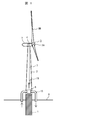
- the wind turbine generator of this embodiment includes a rotor 3 composed of a hub 3A and blades 3B, a main shaft (not shown) connected to the hub 3A and a speed increasing gear (not shown). ),
- the nacelle 5 that houses the generator 4 and other electrical components, and supports the rotor 3 via the main shaft, and supports the nacelle 5 on the top, Is a wind power generation facility that is generally constructed from a tower 2 that is fixed to the foundation 1 on the opposite side, and is installed on the ocean.
- the bottom of the tower 2 fixed to the portion protruding from the sea water 8 of the foundation 1 fixed to the sea bottom (in the present invention, the tower 2 A heat exchanger 6 is provided at the bottom of the tower (less than half of the height), and this heat exchanger 6 is provided with a pipe 13 that guides the seawater 8 to exchange heat with the air in the tower 2 and then discharges it into the sea. Furthermore, a pump 9 that sucks up the seawater 8 from the sea is installed in the middle of the tower 2 of the pipe 13 so that the seawater 8 passing through the heat exchanger 6 is circulated by the pump 9 through the pipe 13. It has become.
- a duct 7 that guides the air in the cooled tower 2 to the nacelle 5 is installed in the tower 2 (see FIG. 1), and the air in the cooled tower 2 is installed above the heat exchanger 6.
- the fan 10 is guided to the duct 7.
- the seawater 8 sucked up by the pump 9 from the sea via the pipe 13 is discharged into the sea through the heat exchanger 6.
- the seawater 8 and the tower 2 are discharged by the heat exchanger 6. Heat is exchanged with the air inside, and the air inside the tower 2 is cooled.
- the equipment (control panel, electrical equipment, transformer, etc.) 15 installed in the tower is cooled by the cooled air in the tower 2 and is guided to the top of the tower 2 via the duct 7 so that the nacelle.
- the generator 4 in 5 can be cooled. Further, the cooling efficiency is further improved by forcibly flowing the cooled air in the tower 2 through the duct 7 using the fan 10.
- FIG. 3 shows a second embodiment of the wind power generation facility of the present invention. Note that the same components as those in the first embodiment are denoted by the same reference numerals, and the description thereof is omitted.
- FIG. 3 differs from the first embodiment in that the heat exchanger 6A is installed not on the inside of the tower 2 but on the side wall of the outer bottom portion of the tower 2.
- the heat exchanger 6A is provided with a pipe 14 that guides the seawater 8 and exchanges heat with the air in the tower 2 and the side wall of the tower 2 and then discharges it into the sea.
- a pump 9 that sucks up 8 from the sea is installed, and the seawater 8 that passes through the heat exchanger 6 ⁇ / b> A installed on the side wall of the outer bottom of the tower 2 is circulated by the pump 9 via a pipe 14.
- Other configurations are the same as in the embodiment.
- the same effect can be obtained even if the tower 2 and the heat exchanger 6A are integrated.
- a structure in which seawater is directly applied to the outer wall of the tower 2 or a part of the tower 2 is a heat exchanger is conceivable.
- FIG. 4 shows a third embodiment of the wind power generation facility of the present invention.
- symbol is used about the thing of the same structure as Example 2, and the description is abbreviate
- Example 3 shown in FIG. 4 is a modification of Example 2.
- a heat exchanger 6 is also installed at the bottom of the tower 2 and installed on the side of the heat exchanger 6 at the bottom of the tower 2 and the outer bottom of the tower 2.
- the second embodiment is different from the second embodiment in that a refrigerant circulation line 11A through which a refrigerant (for example, fresh water) circulates between both the heat exchanger 6A is circulated through a pipe.
- the heat exchanger 6A exchanges heat between the seawater 8 and the refrigerant in the refrigerant circulation line 11A to cool the refrigerant, and the refrigerant is transferred to the heat exchanger 6 through the refrigerant circulation line 11A.
- the heat exchanger 6 exchanges heat with the air in the tower 2 to cool the air in the tower 2, so that the same effect as in the second embodiment can be obtained.
- FIG. 5 shows a fourth embodiment of the wind power generation facility of the present invention. Note that the same components as those in the first embodiment are denoted by the same reference numerals, and the description thereof is omitted.
- Example 4 shown in FIG. 5 is a modification of Example 1.
- the tower interior 2B isolated from the tower interior 2A in which the heat exchanger 6 is housed is disposed on the heat exchanger 6 at the bottom of the tower 2 inside.
- another heat exchanger 6C is installed, and a refrigerant circulation line 11B is provided between the two heat exchangers 6 and 6C at the bottom of the tower 2 to circulate a refrigerant (for example, fresh water) through a pipe.
- a refrigerant for example, fresh water
- Example 4 configured in this manner, the heat exchanger 6 exchanges heat between the seawater 8 and the refrigerant in the refrigerant circulation line 11B to cool the refrigerant, and the refrigerant passes through the refrigerant circulation line 11B to the heat exchanger 6C.
- the heat exchange with the air in the tower 2 is performed by the heat exchanger 6C, and the air in the tower 2 is cooled. Therefore, the same effect as in the first embodiment can be obtained. Even if seawater 8 leaks from the heat exchanger 6, the room in which the heat exchanger 6 is installed is isolated from the others, so there is no possibility that salt will spread throughout the tower 2.
- the heat exchanger 6 is installed in the isolated tower interior 2A.
- the room in which the heat exchanger 6 is isolated may be provided outside the tower.
- FIG. 6 shows a fifth embodiment of the wind power generation facility of the present invention. Note that the same components as those in the first embodiment are denoted by the same reference numerals, and the description thereof is omitted.
- the heat exchanger 6 is provided at the bottom of the tower 2 fixed to the portion protruding from the seawater 8 of the foundation 1 fixed to the seabed, and the foundation 1 in the seawater 8 is further provided.
- Each of the heat exchangers 6D is provided, and between the two heat exchangers 6 and 6D, a first refrigerant circulation line 12 is provided between which the refrigerant (for example, fresh water) circulates through a pipe. .
- the refrigerant cooled by exchanging heat with the seawater 8 in the heat exchanger 6D in the seawater 8 is guided to the heat exchanger 6 in the tower 2 through the first refrigerant circulation line 12, and the inside of the tower 2
- the heat exchanger 6 heat-exchanges the refrigerant and the air in the tower 2 to cool the air in the tower 2.
- coolant circulation line 12 is circulated through the 1st refrigerant
- FIG. 7 shows a sixth embodiment of the wind power generation facility of the present invention.
- symbol is used about the thing of the same structure as Example 5, and the description is abbreviate
- Example 6 shown in FIG. 7 is a modification of Example 5.
- the tower interior 2B isolated from the tower interior 2A in which the heat exchanger 6 is housed is disposed on the upper portion of the heat exchanger 6 at the bottom of the tower 2.
- the second refrigerant circulation line in which another heat exchanger 6C is installed and the refrigerant (for example, fresh water) circulates between the two heat exchangers 6 and 6C at the inner bottom of the tower 2 through a pipe. It differs from Example 5 by the point provided with 11B.
- the refrigerant cooled by exchanging heat with the seawater 8 in the heat exchanger 6D in the seawater 8 passes through the first refrigerant circulation line 12, and the heat exchanger 6 in the tower 2 is cooled.
- the heat exchanger 6 exchanges heat between the refrigerant in the first refrigerant circulation line 12 and the refrigerant in the second refrigerant circulation line 11B to cool the refrigerant, and this refrigerant passes through the second refrigerant circulation line 11B.
- the heat is exchanged with the air in the tower 2 by the heat exchanger 6C, and the air in the tower 2 is cooled, so that the same effect as in the fifth embodiment is obtained. Even if seawater 8 leaks from the heat exchanger 6, the room in which the heat exchanger 6 is installed is isolated from the others, so there is no possibility that salt will spread throughout the tower 2.
Landscapes
- Engineering & Computer Science (AREA)
- General Engineering & Computer Science (AREA)
- Mechanical Engineering (AREA)
- Chemical & Material Sciences (AREA)
- Combustion & Propulsion (AREA)
- Life Sciences & Earth Sciences (AREA)
- Sustainable Development (AREA)
- Sustainable Energy (AREA)
- Physics & Mathematics (AREA)
- Architecture (AREA)
- Thermal Sciences (AREA)
- Power Engineering (AREA)
- Structural Engineering (AREA)
- Civil Engineering (AREA)
- Wind Motors (AREA)
- Connection Of Motors, Electrical Generators, Mechanical Devices, And The Like (AREA)
Abstract
Description
若しくは、前記風力発電設備は洋上に設置されていると共に、前記基礎近傍の前記タワー及び海中にそれぞれ熱交換器を設け、かつ、この2つの熱交換器の間に、両者を配管を介して冷媒が循環する第1の冷媒循環ラインを備え、海中の前記熱交換器で海水と熱交換して冷却された前記冷媒が前記第1の冷媒循環ラインを通って前記タワー内の熱交換器に導かれ、このタワー内の熱交換器で前記冷媒とタワー内の空気とが熱交換され、該タワー内の空気が冷却されることを特徴とする。
Claims (14)
- ハブとブレードから成るロータと、該ロータに前記ハブに接続された主軸を介して接続される発電機と、該発電機を少なくとも収納し、前記主軸を介して前記ロータを軸支するナセルと、該ナセルを頂部に支持し、その頂部とは反対側が基礎に固定されているタワーとを備えた風力発電設備において、
前記基礎近傍の前記タワーに熱交換器を設け、該熱交換器に配管を介して冷却媒体を通すことで、該冷却媒体と前記タワー内の空気とが熱交換され、該タワー内の空気が冷却されることを特徴とする風力発電設備。 - 請求項1に記載の風力発電設備において、
前記風力発電設備は洋上に設置され、かつ、前記冷却媒体は海水であることを特徴とする風力発電設備。 - 請求項2に記載の風力発電設備において、
前記海水を海中から吸い上げるポンプを前記配管の途中に有し、該ポンプで吸い上げられた海水は、前記配管を介して前記熱交換器を通った後、海中に排出されることを特徴とする風力発電設備。 - 請求項3に記載の風力発電設備において、
前記熱交換器は、前記タワー内底部に設置されていることを特徴とする風力発電設備。 - 請求項3に記載の風力発電設備において、
前記熱交換器は、前記タワー外底部の側壁に設置されていることを特徴とする風力発電設備。 - 請求項5に記載の風力発電設備において、
前記タワー内底部に熱交換器を設置し、このタワー内底部の熱交換器とタワー外底部の熱交換器の間に、両者を配管を介して冷媒が循環する冷媒循環ラインを備えていることを特徴とする風力発電設備。 - 請求項4に記載の風力発電設備において、
前記タワー内底部の熱交換器の上部に、この熱交換器が収納されているタワー内部と隔離されたタワー内部に別の熱交換器を設置し、この隔離されたタワー内に設置された2つの熱交換器の間に、両者を配管を介して冷媒が循環する冷媒循環ラインを備えていることを特徴とする風力発電設備。 - 請求項1乃至7のいずれかに記載の風力発電設備において、
前記タワー内に、冷却された該タワー内の空気を前記ナセルに導くダクトが設置されていることを特徴とする風力発電設備。 - 請求項8に記載の風力発電設備において、
冷却された前記タワー内の空気は、前記熱交換器の近傍に設置されたファンによって前記ダクトに導かれていることを特徴とする風力発電設備。 - ハブとブレードから成るロータと、該ロータに前記ハブに接続された主軸を介して接続される発電機と、該発電機を少なくとも収納し、前記主軸を介して前記ロータを軸支するナセルと、該ナセルを頂部に支持し、その頂部とは反対側が基礎に固定されているタワーとを備えた風力発電設備において、
前記風力発電設備は洋上に設置されていると共に、前記基礎近傍の前記タワー及び海中にそれぞれ熱交換器を設け、かつ、この2つの熱交換器の間に、両者を配管を介して冷媒が循環する第1の冷媒循環ラインを備え、海中の前記熱交換器で海水と熱交換して冷却された前記冷媒が前記第1の冷媒循環ラインを通って前記タワー内の熱交換器に導かれ、このタワー内の熱交換器で前記冷媒とタワー内の空気とが熱交換され、該タワー内の空気が冷却されることを特徴とする風力発電設備。 - 請求項10に記載の風力発電設備において、
前記第1の冷媒循環ラインの途中に、前記冷媒を循環させるポンプが設置されていることを特徴とする風力発電設備。 - 請求項10又は11に記載の風力発電設備において、
前記タワー内底部の熱交換器の上部に、この熱交換器が収納されているタワー内部と隔離されたタワー内部に別の熱交換器を設置し、この隔離されたタワー内に設置された2つの熱交換器の間に、両者を配管を介して冷媒が循環する第2の冷媒循環ラインを備えていることを特徴とする風力発電設備。 - 請求項10乃至12のいずれかに記載の風力発電設備において、
前記タワー内に、冷却された該タワー内の空気を前記ナセルに導くダクトが設置されていることを特徴とする風力発電設備。 - 請求項13に記載の風力発電設備において、
冷却された前記タワー内の空気は、前記熱交換器の近傍に設置されたファンによって前記ダクトに導かれていることを特徴とする風力発電設備。
Priority Applications (7)
| Application Number | Priority Date | Filing Date | Title |
|---|---|---|---|
| KR1020137020442A KR101571614B1 (ko) | 2011-02-04 | 2011-02-04 | 풍력 발전 설비 |
| CA2826392A CA2826392C (en) | 2011-02-04 | 2011-02-04 | Cooling system for a wind turbine generator system |
| JP2012555655A JP5636444B2 (ja) | 2011-02-04 | 2011-02-04 | 風力発電設備 |
| US13/983,208 US9458736B2 (en) | 2011-02-04 | 2011-02-04 | Wind turbine generator system |
| EP11857762.6A EP2672114A4 (en) | 2011-02-04 | 2011-02-04 | Wind turbine facility |
| AU2011357986A AU2011357986B2 (en) | 2011-02-04 | 2011-02-04 | Wind turbine facility |
| PCT/JP2011/052327 WO2012105032A1 (ja) | 2011-02-04 | 2011-02-04 | 風力発電設備 |
Applications Claiming Priority (1)
| Application Number | Priority Date | Filing Date | Title |
|---|---|---|---|
| PCT/JP2011/052327 WO2012105032A1 (ja) | 2011-02-04 | 2011-02-04 | 風力発電設備 |
Publications (1)
| Publication Number | Publication Date |
|---|---|
| WO2012105032A1 true WO2012105032A1 (ja) | 2012-08-09 |
Family
ID=46602273
Family Applications (1)
| Application Number | Title | Priority Date | Filing Date |
|---|---|---|---|
| PCT/JP2011/052327 Ceased WO2012105032A1 (ja) | 2011-02-04 | 2011-02-04 | 風力発電設備 |
Country Status (7)
| Country | Link |
|---|---|
| US (1) | US9458736B2 (ja) |
| EP (1) | EP2672114A4 (ja) |
| JP (1) | JP5636444B2 (ja) |
| KR (1) | KR101571614B1 (ja) |
| AU (1) | AU2011357986B2 (ja) |
| CA (1) | CA2826392C (ja) |
| WO (1) | WO2012105032A1 (ja) |
Cited By (5)
| Publication number | Priority date | Publication date | Assignee | Title |
|---|---|---|---|---|
| JP2013164031A (ja) * | 2012-02-10 | 2013-08-22 | Mitsubishi Heavy Ind Ltd | 風力発電装置 |
| JP2014045114A (ja) * | 2012-08-28 | 2014-03-13 | Hitachi Industrial Equipment Systems Co Ltd | 油入変圧器 |
| US10006646B2 (en) | 2015-04-30 | 2018-06-26 | Samsung Electronics Co., Ltd. | Outdoor unit of air conditioner and control device for the outdoor unit |
| JP2018537623A (ja) * | 2015-12-28 | 2018-12-20 | ヴォッベン プロパティーズ ゲーエムベーハー | 風力タービンおよび風力タービン用冷却装置 |
| JP2024173260A (ja) * | 2023-06-02 | 2024-12-12 | 株式会社リビエラ | 水中熱利用システム |
Families Citing this family (10)
| Publication number | Priority date | Publication date | Assignee | Title |
|---|---|---|---|---|
| JP5595057B2 (ja) * | 2010-02-08 | 2014-09-24 | 三菱重工業株式会社 | 風力発電装置 |
| DE102015217035A1 (de) * | 2015-09-04 | 2017-03-09 | Wobben Properties Gmbh | Windenergieanlage und Verfahren zum Steuern einer Kühlung einer Windenergieanlage |
| CN105736249B (zh) * | 2016-01-28 | 2018-12-18 | 中交第三航务工程局有限公司宁波分公司 | 风电机组和承载该风电机组的运输船及吊装方法 |
| CN105715464B (zh) * | 2016-01-28 | 2018-12-18 | 中交第三航务工程局有限公司宁波分公司 | 风电机组的吊装方法 |
| DE102016103101A1 (de) * | 2016-02-23 | 2017-08-24 | Wobben Properties Gmbh | Verfahren und Windparkregelungsmodul zum Regeln eines Windparks |
| CN108661866B (zh) * | 2018-03-30 | 2020-01-31 | 北京金风科创风电设备有限公司 | 风力发电机组 |
| US10978943B2 (en) * | 2019-04-03 | 2021-04-13 | General Electric Company | System and method for auto-ramping and energy dump for a superconducting wind turbine generator |
| CN113530771B (zh) * | 2021-08-30 | 2023-06-27 | 上海凯士比泵有限公司 | 一种利用地下水源的风力发电机组外部循环冷却系统 |
| DE102023114307A1 (de) * | 2023-05-31 | 2024-12-05 | Rwe Generation Se | Offshore-System |
| CN118959258B (zh) * | 2024-10-17 | 2025-01-28 | 大唐景泰新能源有限公司 | 一种风力发电机冷却回路 |
Citations (3)
| Publication number | Priority date | Publication date | Assignee | Title |
|---|---|---|---|---|
| JPS6477444A (en) * | 1987-09-18 | 1989-03-23 | Hitachi Ltd | Generator cooling device |
| JPH1020081A (ja) * | 1996-07-09 | 1998-01-23 | Toshiba Corp | 原子力発電所の海水冷却系設備 |
| JP2003504562A (ja) * | 1999-07-14 | 2003-02-04 | アロイス・ヴォベン | 閉冷却回路を有する風力利用設備 |
Family Cites Families (11)
| Publication number | Priority date | Publication date | Assignee | Title |
|---|---|---|---|---|
| ES2231183T3 (es) * | 1999-05-07 | 2005-05-16 | Neg Micon A/S | Turbina eolica marina con refrigeracion por liquido. |
| DE10016913A1 (de) * | 2000-04-05 | 2001-10-18 | Aerodyn Eng Gmbh | Offshore-Windenergieanlage mit einem Wärmetauschersystem |
| DE10324228B4 (de) * | 2003-05-28 | 2006-02-16 | Rittal Gmbh & Co. Kg | Kühlvorrichtung für eine Offshore-Windenergieanlage |
| DE102004063508B4 (de) * | 2004-12-27 | 2008-10-16 | Siemens Ag | Elektrisches Bauteil mit Kühlkreislauf für den Unterwasserbetrieb |
| ES2330491B1 (es) * | 2007-05-25 | 2010-09-14 | GAMESA INNOVATION & TECHNOLOGY, S.L. | Sistema de climatizacion para aerogeneradores. |
| JP2009138555A (ja) | 2007-12-04 | 2009-06-25 | Mitsubishi Heavy Ind Ltd | 風力発電装置 |
| WO2010010442A2 (en) * | 2008-07-23 | 2010-01-28 | Clipper Windpower Technology, Inc. | Wind turbine tower heat exchanger |
| PT2151833E (pt) * | 2008-08-07 | 2013-04-30 | Starkstrom Geraetebau Gmbh | Sistema transformador |
| US8047774B2 (en) * | 2008-09-11 | 2011-11-01 | General Electric Company | System for heating and cooling wind turbine components |
| EP2376778B1 (en) * | 2008-12-17 | 2017-02-08 | XEMC Darwind BV | Wind turbine comprising a cooling circuit |
| ES2412272T3 (es) * | 2010-09-03 | 2013-07-10 | Abb Ag | Sistema de refrigeración para una disposición costa afuera |
-
2011
- 2011-02-04 KR KR1020137020442A patent/KR101571614B1/ko not_active Expired - Fee Related
- 2011-02-04 EP EP11857762.6A patent/EP2672114A4/en not_active Withdrawn
- 2011-02-04 CA CA2826392A patent/CA2826392C/en not_active Expired - Fee Related
- 2011-02-04 JP JP2012555655A patent/JP5636444B2/ja not_active Expired - Fee Related
- 2011-02-04 AU AU2011357986A patent/AU2011357986B2/en not_active Expired - Fee Related
- 2011-02-04 US US13/983,208 patent/US9458736B2/en active Active
- 2011-02-04 WO PCT/JP2011/052327 patent/WO2012105032A1/ja not_active Ceased
Patent Citations (3)
| Publication number | Priority date | Publication date | Assignee | Title |
|---|---|---|---|---|
| JPS6477444A (en) * | 1987-09-18 | 1989-03-23 | Hitachi Ltd | Generator cooling device |
| JPH1020081A (ja) * | 1996-07-09 | 1998-01-23 | Toshiba Corp | 原子力発電所の海水冷却系設備 |
| JP2003504562A (ja) * | 1999-07-14 | 2003-02-04 | アロイス・ヴォベン | 閉冷却回路を有する風力利用設備 |
Non-Patent Citations (1)
| Title |
|---|
| See also references of EP2672114A4 * |
Cited By (7)
| Publication number | Priority date | Publication date | Assignee | Title |
|---|---|---|---|---|
| JP2013164031A (ja) * | 2012-02-10 | 2013-08-22 | Mitsubishi Heavy Ind Ltd | 風力発電装置 |
| JP2014045114A (ja) * | 2012-08-28 | 2014-03-13 | Hitachi Industrial Equipment Systems Co Ltd | 油入変圧器 |
| US10006646B2 (en) | 2015-04-30 | 2018-06-26 | Samsung Electronics Co., Ltd. | Outdoor unit of air conditioner and control device for the outdoor unit |
| JP2018537623A (ja) * | 2015-12-28 | 2018-12-20 | ヴォッベン プロパティーズ ゲーエムベーハー | 風力タービンおよび風力タービン用冷却装置 |
| US11002253B2 (en) | 2015-12-28 | 2021-05-11 | Wobben Properties Gmbh | Wind turbine and cooling device for a wind turbine |
| JP2024173260A (ja) * | 2023-06-02 | 2024-12-12 | 株式会社リビエラ | 水中熱利用システム |
| JP7648218B2 (ja) | 2023-06-02 | 2025-03-18 | 株式会社リビエラ | 水中熱利用システム |
Also Published As
| Publication number | Publication date |
|---|---|
| EP2672114A4 (en) | 2017-05-03 |
| KR20130109227A (ko) | 2013-10-07 |
| AU2011357986B2 (en) | 2015-10-29 |
| US9458736B2 (en) | 2016-10-04 |
| EP2672114A1 (en) | 2013-12-11 |
| JPWO2012105032A1 (ja) | 2014-07-03 |
| AU2011357986A1 (en) | 2013-09-05 |
| CA2826392C (en) | 2016-03-22 |
| JP5636444B2 (ja) | 2014-12-03 |
| KR101571614B1 (ko) | 2015-11-24 |
| US20130309093A1 (en) | 2013-11-21 |
| CA2826392A1 (en) | 2012-08-09 |
Similar Documents
| Publication | Publication Date | Title |
|---|---|---|
| JP5636444B2 (ja) | 風力発電設備 | |
| JP5072994B2 (ja) | 風力発電装置 | |
| JP4950367B1 (ja) | 再生エネルギー型発電装置 | |
| US8640478B2 (en) | Nacelle cooling system for wind turbine | |
| JP5550508B2 (ja) | 風力発電装置 | |
| JP2009138555A (ja) | 風力発電装置 | |
| US20110304149A1 (en) | Wind turbine comprising a cooling circuit | |
| JP5318740B2 (ja) | 洋上風車 | |
| JPWO2013021487A1 (ja) | 風力発電装置 | |
| WO2013111259A1 (ja) | 風力発電設備 | |
| CN102953940A (zh) | 风力发电机 | |
| JP2009185640A (ja) | 風力発電装置 | |
| JP5992176B2 (ja) | 風力発電装置 | |
| JP2014190314A (ja) | 風力発電装置 | |
| KR101314812B1 (ko) | 해상용 풍력 발전기의 타워 냉각 시스템 | |
| TWI534345B (zh) | Wind power generation equipment | |
| JP5025337B2 (ja) | ポンプ設備 | |
| CN106481499A (zh) | 潮流能发电机直接热交换冷却结构 | |
| CN106401840A (zh) | 潮流能发电机外壁通风热交换冷却结构 | |
| HK1160904A (en) | Nacelle cooling system for wind turbine |
Legal Events
| Date | Code | Title | Description |
|---|---|---|---|
| 121 | Ep: the epo has been informed by wipo that ep was designated in this application |
Ref document number: 11857762 Country of ref document: EP Kind code of ref document: A1 |
|
| WWE | Wipo information: entry into national phase |
Ref document number: 2012555655 Country of ref document: JP |
|
| ENP | Entry into the national phase |
Ref document number: 20137020442 Country of ref document: KR Kind code of ref document: A Ref document number: 2826392 Country of ref document: CA |
|
| WWE | Wipo information: entry into national phase |
Ref document number: 13983208 Country of ref document: US Ref document number: 2011857762 Country of ref document: EP |
|
| NENP | Non-entry into the national phase |
Ref country code: DE |
|
| ENP | Entry into the national phase |
Ref document number: 2011357986 Country of ref document: AU Date of ref document: 20110204 Kind code of ref document: A |