WO2012105105A1 - 電力管理システム及び電力管理方法 - Google Patents
電力管理システム及び電力管理方法 Download PDFInfo
- Publication number
- WO2012105105A1 WO2012105105A1 PCT/JP2011/076291 JP2011076291W WO2012105105A1 WO 2012105105 A1 WO2012105105 A1 WO 2012105105A1 JP 2011076291 W JP2011076291 W JP 2011076291W WO 2012105105 A1 WO2012105105 A1 WO 2012105105A1
- Authority
- WO
- WIPO (PCT)
- Prior art keywords
- consumer
- power
- predetermined
- amount
- power generation
- Prior art date
- Legal status (The legal status is an assumption and is not a legal conclusion. Google has not performed a legal analysis and makes no representation as to the accuracy of the status listed.)
- Ceased
Links
Images

Classifications
-
- H—ELECTRICITY
- H02—GENERATION; CONVERSION OR DISTRIBUTION OF ELECTRIC POWER
- H02J—ELECTRIC POWER NETWORKS; CIRCUIT ARRANGEMENTS OR SYSTEMS FOR SUPPLYING OR DISTRIBUTING ELECTRIC POWER; SYSTEMS FOR STORING ELECTRIC ENERGY
- H02J3/00—Circuit arrangements for AC mains or AC distribution networks
- H02J3/38—Arrangements for feeding a single network from two or more generators or sources in parallel; Arrangements for feeding already energised networks from additional generators or sources in parallel
- H02J3/46—Controlling the sharing of generated power between the generators, sources or networks
- H02J3/466—Scheduling or selectively controlling the operation of the generators or sources, e.g. connecting or disconnecting generators to meet a demand
-
- G—PHYSICS
- G06—COMPUTING OR CALCULATING; COUNTING
- G06F—ELECTRIC DIGITAL DATA PROCESSING
- G06F1/00—Details not covered by groups G06F3/00 - G06F13/00 and G06F21/00
- G06F1/26—Power supply means, e.g. regulation thereof
- G06F1/266—Arrangements to supply power to external peripherals either directly from the computer or under computer control, e.g. supply of power through the communication port, computer controlled power-strips
-
- G—PHYSICS
- G06—COMPUTING OR CALCULATING; COUNTING
- G06F—ELECTRIC DIGITAL DATA PROCESSING
- G06F1/00—Details not covered by groups G06F3/00 - G06F13/00 and G06F21/00
- G06F1/26—Power supply means, e.g. regulation thereof
- G06F1/32—Means for saving power
- G06F1/3203—Power management, i.e. event-based initiation of a power-saving mode
-
- Y—GENERAL TAGGING OF NEW TECHNOLOGICAL DEVELOPMENTS; GENERAL TAGGING OF CROSS-SECTIONAL TECHNOLOGIES SPANNING OVER SEVERAL SECTIONS OF THE IPC; TECHNICAL SUBJECTS COVERED BY FORMER USPC CROSS-REFERENCE ART COLLECTIONS [XRACs] AND DIGESTS
- Y02—TECHNOLOGIES OR APPLICATIONS FOR MITIGATION OR ADAPTATION AGAINST CLIMATE CHANGE
- Y02E—REDUCTION OF GREENHOUSE GAS [GHG] EMISSIONS, RELATED TO ENERGY GENERATION, TRANSMISSION OR DISTRIBUTION
- Y02E10/00—Energy generation through renewable energy sources
- Y02E10/50—Photovoltaic [PV] energy
- Y02E10/56—Power conversion systems, e.g. maximum power point trackers
Definitions
- the present invention relates to a power management system and a power management method for managing a power system connected with a photovoltaic (PV) system.
- PV photovoltaic
- the surplus power problem means that there are a large number of consumers who sell to the power company the surplus power generated by the PV system that cannot be consumed by consumers equipped with the PV system, resulting in excessive power supply in the entire power system. It is a problem that becomes.
- the power supply amount in the power system is optimized by adjusting the power generation amount by a controllable power generation facility such as a thermal power plant. Balance was maintained.
- a controllable power generation facility such as a thermal power plant.
- balance was maintained.
- PV systems become widespread in the future, surplus power exceeding the adjustment capacity of this thermal power plant is expected, and in the worst case, it is recognized as a serious problem that power supply / demand balance is broken and power outage is caused. It became so.
- Patent Document 1 proposes a charge / discharge control method for efficiently storing surplus power in a storage battery held by a consumer.
- the storage battery is still expensive, and the above-described surplus power problem is solved. It is thought that it will take years before a sufficient number or capacity of storage batteries become widespread.
- Patent Document 2 includes a low-voltage system including a consumer with a distributed power source and a high-voltage system to which the low-voltage system is connected.
- a high-voltage system is abnormal, the low-voltage system is disconnected from the high-voltage system, and the power generated by the distributed power source is interchanged between consumers in the low-voltage system.
- the method of not generating surplus power by suppressing the amount of power generated by the PV system is equivalent to discarding the green power generated by the PV system, and creating a sustainable society. It is not efficient as a method of using the PV system to be introduced.
- the method of consuming electric power within the consumer having the PV system at the timing when the control of the amount of power generation for the PV system is entered demands an unreasonable power demand from the consumer and impairs the benefit of the consumer. There is a fear.
- an object of the present invention is to provide a power management system and a power management method that contribute to solving a surplus power problem in a power system interconnected with a PV system.
- a power management system of the present invention includes at least one or more first consumers having a photovoltaic power generation system, At least one second consumer having a controllable load; Is a power management system that manages the power grid
- the first consumer and the second consumer comprise a consumer energy management system that controls the amount of power generated by the photovoltaic power generation system and / or the controllable load
- the power management system includes a server device connected to the consumer energy management system so that data can be transmitted and received via a network, The server device The amount of surplus power expected in a predetermined time zone on a predetermined day when surplus power is expected to be generated by the solar power generation system notified from the consumer energy management system, and predicted in the predetermined time zone on the predetermined day Based on the power demand amount of the second consumer, the power demand amount of the second consumer in the predetermined time zone on the predetermined day is greater than the surplus power amount generated in the first consumer
- the first consumer and the second consumer are combined so as to be a quantity, and the first consumer with the control
- the power management method of the present invention includes at least one or more first consumers having a photovoltaic power generation system, At least one second consumer having a controllable load; Is a power management method for managing an interconnected power system, An energy management system for a consumer that controls the amount of power generated by the solar power generation system and / or the controllable load provided in the first consumer is predetermined to generate surplus power by the solar power generation system.
- the consumer energy management system provided in the second consumer notifies the server device of the power demand of the second consumer expected in a predetermined time zone on the predetermined day
- the server device is The surplus power amount that is predicted from the consumer energy management system in the predetermined time zone on the predetermined day and the power demand amount of the second consumer that is predicted in the predetermined time zone on the predetermined day.
- the power demand of the second consumer in the predetermined time zone on the predetermined day is equal to or greater than the surplus power generated by the first consumer. This is a method in which surplus power generated by the first consumer is consumed by the controllable load under the control of the consumer energy management system provided in the second consumer in combination with the second consumer.
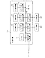
- FIG. 1 is a block diagram illustrating a configuration example of a power system according to the present invention.
- FIG. 2 is a block diagram showing a configuration example of the central server shown in FIG.
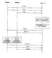
- FIG. 3 is a sequence diagram showing the procedure of the power management method of the present invention.
- a consumer having a PV system (first consumer) An (n is a positive integer) and a controllable load (electric vehicle, stationary storage battery, heat pump water heater, etc.) (Second consumer) Bn (n is a positive integer) is combined, and surplus power by the PV system of consumer An is consumed by a controllable load provided in the combined consumer Bn.
- the customer An and the customer Bn that perform such cooperative operation may be combined, for example, in a one-to-one manner as an example of the simplest control.
- the combination of the consumer An and the consumer Bn includes the amount of surplus power expected in the customer An in a predetermined time period on which a surplus power is expected to be generated by the PV system and the predetermined time period on the predetermined day.
- the surplus power amount and the power demand amount by the controllable load are the same, or the controllable load is greater than the surplus power amount, based on the expected power demand by the controllable load included in the consumer Bn.
- the customer Bn does not have a PV system but has only a controllable load.
- the reason why the combination of the consumer An and the consumer Bn is determined based on the surplus power amount of the consumer An and the power demand amount of the consumer Bn in a predetermined time zone on an expected predetermined day is to eliminate surplus power.
- QOL Quality of Life
- QOL Quality of Life
- the power supply and demand of the entire system can be accurately predicted based on the combined customer cluster (customers An, Bn).
- a controllable power generation facility (such as a thermal power plant) capable of generating power can be prepared according to the expected power supply and demand.
- addition and reduction of other consumers An and Bn can be considered so that the amount of power generated by the PV system ⁇ the electric power demand amount. Control becomes easy.
- the surplus power amount by the PV system and the power demand amount by the controllable load are calculated by, for example, a well-known HEMS (Home Energy Management System) provided by the customer, and the HEMS of each customer via the network Notify the connected CEMS (Central Energy Management System: hereinafter referred to as the central server).
- the central server selects the consumers An and Bn to operate in a coordinated manner from the surplus power amount in the predetermined time notified from the consumer An and the power demand amount by the controllable load notified from the customer Bn.
- an energy storage such as a storage battery that can store energy such as electric power or heat, a heat pump water heater, or a storage battery of an electric vehicle.
- FIG. 1 is a block diagram showing a configuration example of the power system of the present invention.
- the power system of the present invention includes at least one consumer An having a PV system and at least a controllable load CL that does not have a PV system. It is the structure which has the central server (server apparatus) 120 connected so that communication is possible via the network 110 with one or more consumers Bn and each consumer An and Bn.
- server apparatus server apparatus
- the consumers An and Bn include a HEMS that controls the amount of power generated by the PV system and / or the controllable load CL.
- the central server 120 and the HEMS for each of the consumers An and Bn are, for example, the well-known Internet, PLC (Power Line Data) is transmitted and received via the network 110 using wired communication means such as Communications) or optical fiber, or wireless communication means such as Zigbee, WiFi, or WiMax.
- the HEMS may use any device as long as it can control the amount of power generated by the PV system and the controllable load CL, and can transmit and receive data to and from the central server 120. You may implement
- the PV system is, for example, a PC panel (Power Conditioning System) that generates power using solar energy, and converts DC power generated by the PV panel into AC power suitable for the power system 100 and supplies it to a distribution line. ).
- PC panel Power Conditioning System
- the controllable load CL can store energy, for example, as described above, such as an eco-cute heat pump water heater, an electric vehicle, a plug-in hybrid electric vehicle, a stationary storage battery, etc. It is a device that can be controlled.
- the controllable load CL may include a power device such as an automatic dishwasher or a washing machine that does not impair the convenience (does not impair the QoL) even if it does not operate at the consumer's will.
- the central server 120 can be realized by a computer as shown in FIG.
- the computer shown in FIG. 2 outputs a processing device 10 that executes predetermined processing according to a program, an input device 20 for inputting commands and information to the processing device 10, and a processing result of the processing device 10.
- Output device 30 outputs a processing device 10 that executes predetermined processing according to a program, an input device 20 for inputting commands and information to the processing device 10, and a processing result of the processing device 10.
- the processing device 10 includes a CPU 11, a main storage device 12 that temporarily holds information necessary for the processing of the CPU 11, a recording medium 13 on which a program for causing the CPU 11 to execute the processing of the present invention is recorded, and will be described later.
- a data storage device 14 that stores power generation history data, a memory control interface unit 15 that controls data transfer with the main storage device 12, the recording medium 13, and the data storage device 14, and an input device 20 and an output device 30.
- the configuration includes an I / O interface unit 16 that is an interface device, a HEMS included in the consumers An and Bn, and a communication control device 17 for transmitting and receiving data, which are connected via a bus 18.
- the processing device 10 executes processing as the central server 120 described later according to the program recorded in the recording medium 13.
- the recording medium 13 may be a magnetic disk, a semiconductor memory, an optical disk, or other recording medium.
- the data storage device 14 does not need to be provided in the processing device 10 and may be an independent device.
- the information processing device can be realized by the same configuration as the computer shown in FIG. 2 except that the program is different.
- FIG. 3 is a sequence diagram showing the procedure of the power management method of the present invention.
- FIG. 3 shows a state in which one set of customer clusters (a set of customer An and customer Bn) and the central server 120 transmit and receive data.
- the central server 120 actually has a large number of demands. Send data to and receive data from the home cluster.
- the HEMS of the customer An measures the power generation amount of the PV system every preset unit time and stores it as power generation history data.
- This power generation history data may be stored in the customer's An HEMS or may be stored in the central server 120.
- the power generation history data may be stored in units of one day, one week, one month, etc. However, assuming that the life of one PV system is about 20 years, it is permanent from the start of power generation until the PV system is discarded. It is desirable to store in.
- the unit time is preferably as short as possible in consideration of variability depending on the weather of the PV system. However, if the unit time is shortened, the frequency of data collection increases and the amount of data also becomes enormous.
- the power generation history data is stored separately after being collected in the central server 120 and associated with sunshine data mounted on another system (business PV system, etc.) in consideration of the position of the customer. It is desirable that
- the HEMS of the consumer An is expected to generate surplus power or suppress power generation by the PV system based on the past sunshine data and sunshine prediction data held by the central server 120 and the power generation history data.
- An expected power generation amount ⁇ P (t) is calculated and transmitted to the central server 120 in a predetermined time zone on a predetermined day.
- the HEMS included in the consumer An obtains the power demand Y An in the predetermined time period on the predetermined day by the controllable load CL of the consumer An before the predetermined day, for example, the day before the predetermined day.
- the HEMS provided in the customer Bn obtains the electric power demand Y Bn in the predetermined time period on the predetermined day due to the controllable load CL of the consumer Bn on the day before the predetermined day.
- Electricity demand Y An , Y Bn is a storage battery that uses consumers An and Bn to forcibly use hot water boiled in a heat pump water heater or to run a car forcibly to secure a charging capacity by an electric vehicle or the like.
- the amount of energy (power amount) that can be stored (stored heat) in the controllable load CL at the time T after the sleep of the consumers An and Bn on the day before the predetermined day so as not to reduce the amount of electricity stored are measured and set as the power demand amounts Y An and Y Bn of the controllable load CL in a predetermined time zone on the next day (predetermined day).
- the HEMS included in the consumers An and Bn transmits the obtained power demands Y An and Y Bn to the central server 120 via the network 110.
- the central server 120 is linked to the same distribution feeder line as a suboptimal combination.
- a combination of the consumers An and Bn to be linked from the consumer is determined.
- the distribution feeder line refers to a high-voltage distribution line for transmitting high-voltage (for example, 6.6 kV) power output from a distribution transformer in a substation.
- the central server 120 is connected to the same distribution substation.
- the combination of consumers An and Bn to be operated in cooperation from the existing customers may be determined, and further the combination of consumers An and Bn to be operated in cooperation from the consumers linked to different distribution substations may be determined. May be.
- the distance between the connection points of the customer An and the customer Bn is long, it cannot be said that the electric power is actually supplied from the customer An to the customer Bn combined, but supply and demand in the entire wide area including the customer cluster It is sufficient if the balance is consistent.
- the central server 120 displays the predicted power generation pattern by the PV system provided by the customer An in the predetermined time zone on the predetermined day. Generated based on power generation history data.
- the predicted power generation pattern is, for example, the weather in a predetermined time zone on a predetermined day using, for example, the power generation history data for one year ago in the predetermined time zone on the predetermined day or the average value of the power generation history data in the predetermined time zone for the past week. Decide in consideration of forecasts and sunshine forecasts.
- the predicted power generation pattern in the predetermined time zone is used for creating a pattern of the amount of stored electricity (heat storage) allocated to the controllable load CL per unit time in the predetermined time zone on the predetermined day.
- the central server 120 uses the electric power demands Y An and Y Bn notified by each customer as the total power storage (heat storage) amount in the predetermined time zone on the predetermined day.
- the amount of stored (heat storage) Y An (t) + Y Bn (t) to be assigned to the control load CL per unit time is determined based on the above R (t). However, Y An (t) + Y Bn (t) is set to be the same value as P (t) or a value larger than P (t).
- the central server 120 notifies the HEMS of the consumer An of the amount of stored electricity (heat storage) Y An (t) assigned to the controllable load CL per unit time in the predetermined time zone on the predetermined day, and the consumer Bn Is stored in the predetermined time zone on the predetermined day with respect to the controllable load CL for the amount of stored electricity (heat storage) Y Bn (t).
- the HEMS of the consumers An and Bn controls the controllable load CL to consume power according to Y An (t) and Y Bn (t) instructed from the central server 120 in the predetermined time zone on the predetermined day. To do.
- the central server 120 measures and accumulates the power generation amount Px (t) on the predetermined day, which is notified from the HEMS of the customer An, and allows each based on the actual measurement value ⁇ Px (t) of the total power generation amount.
- the amount of stored (heat storage) Y An (t) + Y Bn (t) for each unit time ⁇ assigned to each controllable load CL depends on the relationship between ⁇ Px (t) and ⁇ Y An (t) and ⁇ Y Bn (t).
- a method of correcting as follows can be considered. (A) When ⁇ Px (t) ⁇ Y An (t): In this case, the controllable load CL of the consumer An stores the power ( ⁇ Px (t)) actually generated by the PV system, and the controllable load CL of the consumer Bn does not store power.
- the HEMS of the consumer An notifies the central server 120 of the insufficient storage amount ⁇ Y An (t) ⁇ Px (t) in the controllable load CL of the consumer An as the insufficient charge amount Y An ⁇ (t). Further, the HEMS of the customer Bn notifies the central server 120 of the insufficient storage amount ⁇ Y Bn (t) in the controllable load CL of the customer Bn as the insufficient charging amount Y Bn ⁇ (t).
- the HEMS of the customer Bn sends the insufficient storage amount ⁇ Y An (t) + ⁇ Y Bn (t) ⁇ Px (t) in the controllable load CL of the customer Bn to the central server 120 as the insufficient charging amount Y Bn ⁇ (t).
- the controllable load CL of the consumer An stores power according to Y An (t)
- the controllable load CL of the consumer Bn stores power according to Y Bn (t).
- the HEMS of the customer An notifies the central server 120 of surplus power ⁇ Px (t) ⁇ ⁇ Y An (t) + Y Bn (t) ⁇ by the PV system. Based on the notification from the HEMS of the customer An, the central server 120 is the closest to the customer An in the power system 100 and notifies the controllable load CL of the customer who has notified the insufficient charging amount Y Bn ⁇ (t). Is assigned a storage operation of surplus power ⁇ Px (t) ⁇ ⁇ Y An (t) + Y Bn (t) ⁇ .
- the central server 120 to reduce supply and demand imbalance by shifting the timing of power storage (heat storage) operation for the controllable load CL by each customer cluster. For example, if the time for shifting the power storage (heat storage) operation for each customer cluster is set to be sufficiently shorter than the time required for the above-mentioned principle of the same amount (usually 30 minutes), for example, about 10 seconds or 1 minute. Good.
- a customer cluster is formed by one customer An having PV and one customer Bn having a controllable load CL has been described.
- a plurality of consumers Bn may be combined, and a plurality of consumers An may be combined with one consumer Bn.
- the electric power consumption Y An (t) + Y Bn (t) and the predicted power generation amount P (t) need not always strictly satisfy the principle of the same amount at the same time. It is not necessary to consume all surplus power by the customer Bn as a pair. It is sufficient that the central server 120 can appropriately combine the consumers An and Bn so that the surplus power generated in the entire customer by each consumer cluster does not increase.
- the consumer An having the PV system and the PV system are provided so that the amount of power demand by the controllable load CL is surplus power generated by the consumer An or more. Without combining the customer Bn with the controllable load CL and consuming surplus power generated by the customer An by the controllable load CL, while reducing the power generation suppression by the PV system, The surplus power generated can be reduced.
- the controllable load CL may be an electric vehicle (EV) or a plug-in hybrid electric vehicle (PHEV) that is charged by a quick charger or a normal charger.
- EV electric vehicle
- PHEV plug-in hybrid electric vehicle
Landscapes
- Engineering & Computer Science (AREA)
- Theoretical Computer Science (AREA)
- General Engineering & Computer Science (AREA)
- Physics & Mathematics (AREA)
- General Physics & Mathematics (AREA)
- Power Engineering (AREA)
- Computer Hardware Design (AREA)
- Supply And Distribution Of Alternating Current (AREA)
- Management, Administration, Business Operations System, And Electronic Commerce (AREA)
Priority Applications (4)
| Application Number | Priority Date | Filing Date | Title |
|---|---|---|---|
| EP11857508.3A EP2672604A4 (de) | 2011-01-31 | 2011-11-15 | Stromverwaltungssystem und stromverwaltungsverfahren |
| US13/982,408 US9423849B2 (en) | 2011-01-31 | 2011-11-15 | Electric power management system and electric power management method |
| JP2012555691A JP5928346B2 (ja) | 2011-01-31 | 2011-11-15 | 電力管理システム及び電力管理方法 |
| US15/216,012 US10270257B2 (en) | 2011-01-31 | 2016-07-21 | Electric power management system and electric power management method |
Applications Claiming Priority (2)
| Application Number | Priority Date | Filing Date | Title |
|---|---|---|---|
| JP2011-018322 | 2011-01-31 | ||
| JP2011018322 | 2011-01-31 |
Related Child Applications (2)
| Application Number | Title | Priority Date | Filing Date |
|---|---|---|---|
| US13/982,408 A-371-Of-International US9423849B2 (en) | 2011-01-31 | 2011-11-15 | Electric power management system and electric power management method |
| US15/216,012 Continuation US10270257B2 (en) | 2011-01-31 | 2016-07-21 | Electric power management system and electric power management method |
Publications (1)
| Publication Number | Publication Date |
|---|---|
| WO2012105105A1 true WO2012105105A1 (ja) | 2012-08-09 |
Family
ID=46602337
Family Applications (1)
| Application Number | Title | Priority Date | Filing Date |
|---|---|---|---|
| PCT/JP2011/076291 Ceased WO2012105105A1 (ja) | 2011-01-31 | 2011-11-15 | 電力管理システム及び電力管理方法 |
Country Status (4)
| Country | Link |
|---|---|
| US (2) | US9423849B2 (de) |
| EP (1) | EP2672604A4 (de) |
| JP (1) | JP5928346B2 (de) |
| WO (1) | WO2012105105A1 (de) |
Cited By (15)
| Publication number | Priority date | Publication date | Assignee | Title |
|---|---|---|---|---|
| JP2014128140A (ja) * | 2012-12-27 | 2014-07-07 | Hitachi Ltd | 電力抑制制御システムおよび電力抑制制御方法 |
| WO2015121937A1 (ja) * | 2014-02-13 | 2015-08-20 | 株式会社日立製作所 | 電力融通管理システムおよび電力融通管理方法 |
| JP2016103965A (ja) * | 2014-11-12 | 2016-06-02 | パナソニックIpマネジメント株式会社 | 電力管理方法、電力管理システム、及び、給電装置 |
| JP2017511683A (ja) * | 2014-04-23 | 2017-04-20 | 日本電気株式会社 | 実時間演算のための動的で協調的なマイクログリッドを有する電力分配システム |
| JP2017108526A (ja) * | 2015-12-09 | 2017-06-15 | 積水化学工業株式会社 | 電力管理装置、電力管理方法およびプログラム |
| JP2017153275A (ja) * | 2016-02-25 | 2017-08-31 | オムロン株式会社 | 電力供給経路制御システム、電力供給経路制御方法および電力供給経路制御プログラム |
| WO2017149617A1 (ja) * | 2016-02-29 | 2017-09-08 | 日本電気株式会社 | 制御装置、需給調整制御装置、蓄電装置、出力制御装置、需給調整システム、制御方法、需給調整方法及びプログラム |
| WO2017163655A1 (ja) * | 2016-03-23 | 2017-09-28 | 日本電気株式会社 | 制御装置、制御方法及びプログラム |
| US10197984B2 (en) | 2015-10-12 | 2019-02-05 | International Business Machines Corporation | Automated energy load forecaster |
| JP2019033669A (ja) * | 2018-10-30 | 2019-02-28 | 日本電気株式会社 | 電力制御装置及び発電装置 |
| CN110782165A (zh) * | 2019-10-25 | 2020-02-11 | 深圳供电局有限公司 | 一种网格化的配电网剩余供电容量监控系统 |
| KR20210096571A (ko) * | 2020-01-28 | 2021-08-05 | 한국전자통신연구원 | 주택 대상의 잉여 전력 거래를 위한 전력 관리 장치 및 주택 단지 조합 방법 |
| JP2022189319A (ja) * | 2021-06-11 | 2022-12-22 | トヨタ自動車株式会社 | 充電システム、充電設備、送信装置および通知装置 |
| WO2023157314A1 (ja) * | 2022-02-21 | 2023-08-24 | 日本碍子株式会社 | エネルギーマネジメントシステム、エネルギーマネジメント方法、およびプログラム |
| US11824359B2 (en) | 2020-01-28 | 2023-11-21 | Electronics And Telecommunications Research Institute | Electricity management apparatus for trading dump power for housing, and housing complex association method |
Families Citing this family (6)
| Publication number | Priority date | Publication date | Assignee | Title |
|---|---|---|---|---|
| JP5707369B2 (ja) * | 2012-08-17 | 2015-04-30 | 株式会社東芝 | 充電管理システム |
| US20140228976A1 (en) * | 2013-02-12 | 2014-08-14 | Nagaraja K. S. | Method for user management and a power plant control system thereof for a power plant system |
| US11757304B2 (en) * | 2014-06-23 | 2023-09-12 | Gridbridge, Inc. | Versatile site energy router |
| JP6137497B2 (ja) * | 2014-10-23 | 2017-05-31 | トヨタ自動車株式会社 | 電力供給管理システム |
| CN104934984B (zh) * | 2015-06-12 | 2017-05-24 | 北京交通大学 | 一种基于pv曲线的低压减载自适应整定方法 |
| JP6500661B2 (ja) * | 2015-07-15 | 2019-04-17 | オムロン株式会社 | 発電システム管理装置及びプログラム |
Citations (6)
| Publication number | Priority date | Publication date | Assignee | Title |
|---|---|---|---|---|
| JP2003289627A (ja) * | 2002-03-28 | 2003-10-10 | Osaka Gas Co Ltd | エネルギー需給方法、エネルギー需給システム、需要側装置、管理側装置 |
| JP2006288162A (ja) * | 2005-04-05 | 2006-10-19 | Inst Of Research & Innovation | 電力システムの電力量融通制御方法 |
| JP2007267600A (ja) * | 2004-03-17 | 2007-10-11 | National Institute Of Advanced Industrial & Technology | 系統情報監視システム |
| JP2008125290A (ja) | 2006-11-14 | 2008-05-29 | Central Res Inst Of Electric Power Ind | 低圧系統の自立運転方法及び低圧系統の自立運転システム |
| WO2008117392A1 (ja) * | 2007-03-26 | 2008-10-02 | Vpec, Inc. | 電力システム |
| JP2009284586A (ja) | 2008-05-20 | 2009-12-03 | Nippon Telegr & Teleph Corp <Ntt> | 電力システムおよびその制御方法 |
Family Cites Families (19)
| Publication number | Priority date | Publication date | Assignee | Title |
|---|---|---|---|---|
| US4636931A (en) * | 1985-06-28 | 1987-01-13 | Shikoku Denryoku Kabushiki Kaisha | Photovoltaic power control system |
| US20050165512A1 (en) * | 2004-01-14 | 2005-07-28 | Haso Peljto | Systems and methods for selective power transfer |
| JP2007295680A (ja) | 2006-04-24 | 2007-11-08 | Matsushita Electric Ind Co Ltd | 負荷制御装置 |
| US8103389B2 (en) * | 2006-05-18 | 2012-01-24 | Gridpoint, Inc. | Modular energy control system |
| GB0613192D0 (en) * | 2006-07-01 | 2006-08-09 | Ibm | Methods, apparatus and computer programs for managing persistence |
| US20080046387A1 (en) * | 2006-07-23 | 2008-02-21 | Rajeev Gopal | System and method for policy based control of local electrical energy generation and use |
| JP2008125295A (ja) | 2006-11-14 | 2008-05-29 | Central Res Inst Of Electric Power Ind | 需要家における負荷選択遮断方法及び需要家における負荷選択遮断装置 |
| US7698219B2 (en) * | 2007-01-12 | 2010-04-13 | Clean Power Finance, Inc. | Methods, systems and agreements for increasing the likelihood of repayments under a financing agreement for renewable energy equipment |
| US20090265042A1 (en) * | 2008-04-17 | 2009-10-22 | Mollenkopf James D | System and Method for Providing Voltage Regulation in a Power Distribution System |
| JP5071680B2 (ja) * | 2008-07-07 | 2012-11-14 | ミツミ電機株式会社 | レンズ駆動装置 |
| US8352091B2 (en) * | 2009-01-02 | 2013-01-08 | International Business Machines Corporation | Distributed grid-interactive photovoltaic-based power dispatching |
| JP5350011B2 (ja) * | 2009-02-26 | 2013-11-27 | 三洋電機株式会社 | 系統連系装置及び配電システム |
| JP5470939B2 (ja) | 2009-03-16 | 2014-04-16 | 東京電力株式会社 | 再生可能電力充電システムおよび充電方法 |
| DE102009040090A1 (de) * | 2009-09-04 | 2011-03-10 | Voltwerk Electronics Gmbh | Inseleinheit für ein Energienetz mit einer Steuereinheit zum Steuern eines Energieflusses zwischen der Energieerzeugungseinheit, der Energiespeichereinheit, der Lasteinheit und/oder dem Energienetz |
| JP5807171B2 (ja) * | 2009-09-30 | 2015-11-10 | パナソニックIpマネジメント株式会社 | エネルギーマネジメントシステムおよび給電制御装置 |
| JP2011155710A (ja) * | 2010-01-25 | 2011-08-11 | Sony Corp | 電力管理装置、電子機器及び電力管理方法 |
| JP2011164900A (ja) * | 2010-02-09 | 2011-08-25 | Sony Corp | グリーン発電装置、携帯機器、蓄電装置、及びグリーン電力情報の管理方法 |
| JP5587641B2 (ja) * | 2010-03-10 | 2014-09-10 | パナソニック株式会社 | 電力供給システム |
| US20120109389A1 (en) * | 2010-10-27 | 2012-05-03 | Redwood Systems, Inc. | Distributed power point control |
-
2011
- 2011-11-15 EP EP11857508.3A patent/EP2672604A4/de not_active Withdrawn
- 2011-11-15 JP JP2012555691A patent/JP5928346B2/ja active Active
- 2011-11-15 US US13/982,408 patent/US9423849B2/en active Active
- 2011-11-15 WO PCT/JP2011/076291 patent/WO2012105105A1/ja not_active Ceased
-
2016
- 2016-07-21 US US15/216,012 patent/US10270257B2/en active Active
Patent Citations (6)
| Publication number | Priority date | Publication date | Assignee | Title |
|---|---|---|---|---|
| JP2003289627A (ja) * | 2002-03-28 | 2003-10-10 | Osaka Gas Co Ltd | エネルギー需給方法、エネルギー需給システム、需要側装置、管理側装置 |
| JP2007267600A (ja) * | 2004-03-17 | 2007-10-11 | National Institute Of Advanced Industrial & Technology | 系統情報監視システム |
| JP2006288162A (ja) * | 2005-04-05 | 2006-10-19 | Inst Of Research & Innovation | 電力システムの電力量融通制御方法 |
| JP2008125290A (ja) | 2006-11-14 | 2008-05-29 | Central Res Inst Of Electric Power Ind | 低圧系統の自立運転方法及び低圧系統の自立運転システム |
| WO2008117392A1 (ja) * | 2007-03-26 | 2008-10-02 | Vpec, Inc. | 電力システム |
| JP2009284586A (ja) | 2008-05-20 | 2009-12-03 | Nippon Telegr & Teleph Corp <Ntt> | 電力システムおよびその制御方法 |
Non-Patent Citations (1)
| Title |
|---|
| See also references of EP2672604A4 |
Cited By (27)
| Publication number | Priority date | Publication date | Assignee | Title |
|---|---|---|---|---|
| JP2014128140A (ja) * | 2012-12-27 | 2014-07-07 | Hitachi Ltd | 電力抑制制御システムおよび電力抑制制御方法 |
| WO2015121937A1 (ja) * | 2014-02-13 | 2015-08-20 | 株式会社日立製作所 | 電力融通管理システムおよび電力融通管理方法 |
| JPWO2015121937A1 (ja) * | 2014-02-13 | 2017-03-30 | 株式会社日立製作所 | 電力融通管理システムおよび電力融通管理方法 |
| US10103575B2 (en) | 2014-02-13 | 2018-10-16 | Hitachi, Ltd. | Power interchange management system and power interchange management method for maintaining a balance between power supply and demand |
| JP2017511683A (ja) * | 2014-04-23 | 2017-04-20 | 日本電気株式会社 | 実時間演算のための動的で協調的なマイクログリッドを有する電力分配システム |
| US10284011B2 (en) | 2014-04-23 | 2019-05-07 | Nec Corporation | Electricity distribution system with dynamic cooperative microgrids for real-time operation |
| JP2018061429A (ja) * | 2014-11-12 | 2018-04-12 | パナソニックIpマネジメント株式会社 | 電力管理方法、電力管理システム、及び、給電装置 |
| JP2016103965A (ja) * | 2014-11-12 | 2016-06-02 | パナソニックIpマネジメント株式会社 | 電力管理方法、電力管理システム、及び、給電装置 |
| US10197984B2 (en) | 2015-10-12 | 2019-02-05 | International Business Machines Corporation | Automated energy load forecaster |
| JP2017108526A (ja) * | 2015-12-09 | 2017-06-15 | 積水化学工業株式会社 | 電力管理装置、電力管理方法およびプログラム |
| JP2017153275A (ja) * | 2016-02-25 | 2017-08-31 | オムロン株式会社 | 電力供給経路制御システム、電力供給経路制御方法および電力供給経路制御プログラム |
| WO2017145457A1 (ja) * | 2016-02-25 | 2017-08-31 | オムロン株式会社 | 電力供給経路制御システム、電力供給経路制御方法および電力供給経路制御プログラム |
| WO2017149617A1 (ja) * | 2016-02-29 | 2017-09-08 | 日本電気株式会社 | 制御装置、需給調整制御装置、蓄電装置、出力制御装置、需給調整システム、制御方法、需給調整方法及びプログラム |
| JP2020120581A (ja) * | 2016-02-29 | 2020-08-06 | 日本電気株式会社 | 制御装置及び需給調整制御装置 |
| JPWO2017149617A1 (ja) * | 2016-02-29 | 2018-08-30 | 日本電気株式会社 | 制御装置、需給調整制御装置、蓄電装置、出力制御装置、需給調整システム、制御方法、需給調整方法及びプログラム |
| WO2017163655A1 (ja) * | 2016-03-23 | 2017-09-28 | 日本電気株式会社 | 制御装置、制御方法及びプログラム |
| JPWO2017163655A1 (ja) * | 2016-03-23 | 2019-01-31 | 日本電気株式会社 | 制御装置、制御方法及びプログラム |
| JP7024707B2 (ja) | 2016-03-23 | 2022-02-24 | 日本電気株式会社 | 制御装置、制御方法及びプログラム |
| JP2019033669A (ja) * | 2018-10-30 | 2019-02-28 | 日本電気株式会社 | 電力制御装置及び発電装置 |
| CN110782165B (zh) * | 2019-10-25 | 2022-05-13 | 深圳供电局有限公司 | 一种网格化的配电网剩余供电容量监控系统 |
| CN110782165A (zh) * | 2019-10-25 | 2020-02-11 | 深圳供电局有限公司 | 一种网格化的配电网剩余供电容量监控系统 |
| KR20210096571A (ko) * | 2020-01-28 | 2021-08-05 | 한국전자통신연구원 | 주택 대상의 잉여 전력 거래를 위한 전력 관리 장치 및 주택 단지 조합 방법 |
| KR102546116B1 (ko) | 2020-01-28 | 2023-06-22 | 한국전자통신연구원 | 주택 대상의 잉여 전력 거래를 위한 전력 관리 장치 및 주택 단지 조합 방법 |
| US11824359B2 (en) | 2020-01-28 | 2023-11-21 | Electronics And Telecommunications Research Institute | Electricity management apparatus for trading dump power for housing, and housing complex association method |
| JP2022189319A (ja) * | 2021-06-11 | 2022-12-22 | トヨタ自動車株式会社 | 充電システム、充電設備、送信装置および通知装置 |
| JP7729078B2 (ja) | 2021-06-11 | 2025-08-26 | トヨタ自動車株式会社 | 充電システム、送信装置および通知装置 |
| WO2023157314A1 (ja) * | 2022-02-21 | 2023-08-24 | 日本碍子株式会社 | エネルギーマネジメントシステム、エネルギーマネジメント方法、およびプログラム |
Also Published As
| Publication number | Publication date |
|---|---|
| US20130311000A1 (en) | 2013-11-21 |
| JPWO2012105105A1 (ja) | 2014-07-03 |
| US20160329717A1 (en) | 2016-11-10 |
| EP2672604A4 (de) | 2017-01-04 |
| US10270257B2 (en) | 2019-04-23 |
| US9423849B2 (en) | 2016-08-23 |
| EP2672604A1 (de) | 2013-12-11 |
| JP5928346B2 (ja) | 2016-06-01 |
Similar Documents
| Publication | Publication Date | Title |
|---|---|---|
| JP5928346B2 (ja) | 電力管理システム及び電力管理方法 | |
| JP6168564B2 (ja) | 分散型エネルギー源から、電気エネルギーを供給するための方法及び発電システム | |
| JP5590033B2 (ja) | エネルギーシステム | |
| US10033214B2 (en) | Power supply-demand adjusting apparatus, power system and power supply-demand adjusting method | |
| US20190199131A1 (en) | Power management method, power management server, local control apparatus, and power management system | |
| US20140214219A1 (en) | Energy management system, energy management method, medium, and server | |
| US10326305B1 (en) | Personal power plant system and methods of inverse energy generation | |
| Almeida et al. | Electric vehicles participating in frequency control: Operating islanded systems with large penetration of renewable power sources | |
| US10431985B2 (en) | Power management method | |
| Nizami et al. | Transactive energy trading of residential prosumers using battery energy storage systems | |
| JP2022191478A (ja) | 電力管理装置及び電力管理方法 | |
| WO2015001767A1 (ja) | 制御装置、電力管理システム | |
| JP2018007364A (ja) | 電力管理装置及びプログラム | |
| Ishigaki et al. | Optimal energy management system for isolated micro grids | |
| JP2013162560A (ja) | 需給調整システム | |
| Vatsal et al. | Fast frequency response scheduling considering electric vehicles and renewable generation | |
| US20190190047A1 (en) | Power management method, power management server, local control apparatus, and power management system | |
| JP6543187B2 (ja) | 蓄電池制御方法 | |
| GB2565080A (en) | A System and method for controlling devices in a power distribution network | |
| Ilyushin et al. | Application Methods of Efficient Electricity Storage Systems to Improve Flexibility of Power Systems | |
| Farimani et al. | Effects of demand dispatch on operation of smart hybrid energy systems | |
| KR101397746B1 (ko) | 스마트 전력 관리 방법 및 시스템 | |
| CN121546662A (zh) | 电动车辆状态暗起动充电 | |
| Khoshian et al. | Introducing new ICT-based frequency control strategy in microgrids | |
| Yang et al. | The effect of non-cooperative distributed energy storage on aggregated load profile under real-time pricing |
Legal Events
| Date | Code | Title | Description |
|---|---|---|---|
| 121 | Ep: the epo has been informed by wipo that ep was designated in this application |
Ref document number: 11857508 Country of ref document: EP Kind code of ref document: A1 |
|
| WWE | Wipo information: entry into national phase |
Ref document number: 2011857508 Country of ref document: EP |
|
| ENP | Entry into the national phase |
Ref document number: 2012555691 Country of ref document: JP Kind code of ref document: A |
|
| WWE | Wipo information: entry into national phase |
Ref document number: 13982408 Country of ref document: US |
|
| NENP | Non-entry into the national phase |
Ref country code: DE |