WO2012105116A1 - Corps rotatif de pompe à vide, élément fixe placé pour être opposé à celui-ci, et pompe à vide les comportant - Google Patents
Corps rotatif de pompe à vide, élément fixe placé pour être opposé à celui-ci, et pompe à vide les comportant Download PDFInfo
- Publication number
- WO2012105116A1 WO2012105116A1 PCT/JP2011/077301 JP2011077301W WO2012105116A1 WO 2012105116 A1 WO2012105116 A1 WO 2012105116A1 JP 2011077301 W JP2011077301 W JP 2011077301W WO 2012105116 A1 WO2012105116 A1 WO 2012105116A1
- Authority
- WO
- WIPO (PCT)
- Prior art keywords
- vacuum pump
- rotor
- rotating body
- pump
- reinforced plastic
- Prior art date
- Legal status (The legal status is an assumption and is not a legal conclusion. Google has not performed a legal analysis and makes no representation as to the accuracy of the status listed.)
- Ceased
Links
Images
Classifications
-
- F—MECHANICAL ENGINEERING; LIGHTING; HEATING; WEAPONS; BLASTING
- F04—POSITIVE - DISPLACEMENT MACHINES FOR LIQUIDS; PUMPS FOR LIQUIDS OR ELASTIC FLUIDS
- F04D—NON-POSITIVE-DISPLACEMENT PUMPS
- F04D29/00—Details, component parts, or accessories
- F04D29/02—Selection of particular materials
-
- F—MECHANICAL ENGINEERING; LIGHTING; HEATING; WEAPONS; BLASTING
- F04—POSITIVE - DISPLACEMENT MACHINES FOR LIQUIDS; PUMPS FOR LIQUIDS OR ELASTIC FLUIDS
- F04D—NON-POSITIVE-DISPLACEMENT PUMPS
- F04D19/00—Axial-flow pumps
- F04D19/02—Multi-stage pumps
- F04D19/04—Multi-stage pumps specially adapted to the production of a high vacuum, e.g. molecular pumps
- F04D19/042—Turbomolecular vacuum pumps
-
- F—MECHANICAL ENGINEERING; LIGHTING; HEATING; WEAPONS; BLASTING
- F04—POSITIVE - DISPLACEMENT MACHINES FOR LIQUIDS; PUMPS FOR LIQUIDS OR ELASTIC FLUIDS
- F04D—NON-POSITIVE-DISPLACEMENT PUMPS
- F04D19/00—Axial-flow pumps
- F04D19/02—Multi-stage pumps
- F04D19/04—Multi-stage pumps specially adapted to the production of a high vacuum, e.g. molecular pumps
- F04D19/044—Holweck-type pumps
-
- F—MECHANICAL ENGINEERING; LIGHTING; HEATING; WEAPONS; BLASTING
- F04—POSITIVE - DISPLACEMENT MACHINES FOR LIQUIDS; PUMPS FOR LIQUIDS OR ELASTIC FLUIDS
- F04D—NON-POSITIVE-DISPLACEMENT PUMPS
- F04D29/00—Details, component parts, or accessories
- F04D29/02—Selection of particular materials
- F04D29/023—Selection of particular materials especially adapted for elastic fluid pumps
-
- F—MECHANICAL ENGINEERING; LIGHTING; HEATING; WEAPONS; BLASTING
- F05—INDEXING SCHEMES RELATING TO ENGINES OR PUMPS IN VARIOUS SUBCLASSES OF CLASSES F01-F04
- F05D—INDEXING SCHEME FOR ASPECTS RELATING TO NON-POSITIVE-DISPLACEMENT MACHINES OR ENGINES, GAS-TURBINES OR JET-PROPULSION PLANTS
- F05D2230/00—Manufacture
- F05D2230/30—Manufacture with deposition of material
- F05D2230/31—Layer deposition
-
- F—MECHANICAL ENGINEERING; LIGHTING; HEATING; WEAPONS; BLASTING
- F05—INDEXING SCHEMES RELATING TO ENGINES OR PUMPS IN VARIOUS SUBCLASSES OF CLASSES F01-F04
- F05D—INDEXING SCHEME FOR ASPECTS RELATING TO NON-POSITIVE-DISPLACEMENT MACHINES OR ENGINES, GAS-TURBINES OR JET-PROPULSION PLANTS
- F05D2230/00—Manufacture
- F05D2230/90—Coating; Surface treatment
-
- F—MECHANICAL ENGINEERING; LIGHTING; HEATING; WEAPONS; BLASTING
- F05—INDEXING SCHEMES RELATING TO ENGINES OR PUMPS IN VARIOUS SUBCLASSES OF CLASSES F01-F04
- F05D—INDEXING SCHEME FOR ASPECTS RELATING TO NON-POSITIVE-DISPLACEMENT MACHINES OR ENGINES, GAS-TURBINES OR JET-PROPULSION PLANTS
- F05D2260/00—Function
- F05D2260/95—Preventing corrosion
-
- F—MECHANICAL ENGINEERING; LIGHTING; HEATING; WEAPONS; BLASTING
- F05—INDEXING SCHEMES RELATING TO ENGINES OR PUMPS IN VARIOUS SUBCLASSES OF CLASSES F01-F04
- F05D—INDEXING SCHEME FOR ASPECTS RELATING TO NON-POSITIVE-DISPLACEMENT MACHINES OR ENGINES, GAS-TURBINES OR JET-PROPULSION PLANTS
- F05D2300/00—Materials; Properties thereof
- F05D2300/10—Metals, alloys or intermetallic compounds
- F05D2300/17—Alloys
- F05D2300/173—Aluminium alloys, e.g. AlCuMgPb
-
- F—MECHANICAL ENGINEERING; LIGHTING; HEATING; WEAPONS; BLASTING
- F05—INDEXING SCHEMES RELATING TO ENGINES OR PUMPS IN VARIOUS SUBCLASSES OF CLASSES F01-F04
- F05D—INDEXING SCHEME FOR ASPECTS RELATING TO NON-POSITIVE-DISPLACEMENT MACHINES OR ENGINES, GAS-TURBINES OR JET-PROPULSION PLANTS
- F05D2300/00—Materials; Properties thereof
- F05D2300/20—Oxide or non-oxide ceramics
- F05D2300/21—Oxide ceramics
- F05D2300/2112—Aluminium oxides
-
- F—MECHANICAL ENGINEERING; LIGHTING; HEATING; WEAPONS; BLASTING
- F05—INDEXING SCHEMES RELATING TO ENGINES OR PUMPS IN VARIOUS SUBCLASSES OF CLASSES F01-F04
- F05D—INDEXING SCHEME FOR ASPECTS RELATING TO NON-POSITIVE-DISPLACEMENT MACHINES OR ENGINES, GAS-TURBINES OR JET-PROPULSION PLANTS
- F05D2300/00—Materials; Properties thereof
- F05D2300/40—Organic materials
- F05D2300/43—Synthetic polymers, e.g. plastics; Rubber
-
- F—MECHANICAL ENGINEERING; LIGHTING; HEATING; WEAPONS; BLASTING
- F05—INDEXING SCHEMES RELATING TO ENGINES OR PUMPS IN VARIOUS SUBCLASSES OF CLASSES F01-F04
- F05D—INDEXING SCHEME FOR ASPECTS RELATING TO NON-POSITIVE-DISPLACEMENT MACHINES OR ENGINES, GAS-TURBINES OR JET-PROPULSION PLANTS
- F05D2300/00—Materials; Properties thereof
- F05D2300/60—Properties or characteristics given to material by treatment or manufacturing
- F05D2300/603—Composites; e.g. fibre-reinforced
-
- F—MECHANICAL ENGINEERING; LIGHTING; HEATING; WEAPONS; BLASTING
- F05—INDEXING SCHEMES RELATING TO ENGINES OR PUMPS IN VARIOUS SUBCLASSES OF CLASSES F01-F04
- F05D—INDEXING SCHEME FOR ASPECTS RELATING TO NON-POSITIVE-DISPLACEMENT MACHINES OR ENGINES, GAS-TURBINES OR JET-PROPULSION PLANTS
- F05D2300/00—Materials; Properties thereof
- F05D2300/60—Properties or characteristics given to material by treatment or manufacturing
- F05D2300/611—Coating
Definitions
- this type of vacuum pump for example, a composite turbo molecular pump described in Patent Document 1 is known.
- this composite turbomolecular pump exhausts gas by the interaction between the rotary blade (2a) and the fixed blade (2b).
- a turbo molecular pump part (2) as a blade exhaust part and a thread groove pump part (3) for exhausting gas through a thread groove (7a) are provided, and the rotor (4a) of the turbo molecular pump part (2) is made of aluminum.
- the rotor (6) of the thread groove pump section (3) is made of an alloy, and is made of CFRP (carbon fiber reinforced plastics).
- the composite molecular pump including the turbo molecular pump part (2) and the thread groove pump part (3) as described in Patent Document 1 described above is light and strong in the rotor (6) of the thread groove pump part (3). Since the part is made of a high fiber reinforced plastic material, by increasing the rotational speed of the rotor (6) or by enlarging the diameter of the rotor (6) rather than the rotor made of aluminum alloy, The peripheral speed of the rotor (6) can be improved, and the exhaust capacity of the thread groove pump part (3) can be increased.
- the peripheral speed of the rotor (6) reaches a speed close to the sound speed of the exhausted gas in the thread groove pump section (3).
- the temperature of the rotor (6) rises due to the heat (friction heat) generated by the friction between the gas exhausted in the groove pump section (3) and the rotor (6), and the CFRP which is the constituent material of the rotor (6) is allowed. If the temperature is exceeded, the strength of the CFRP material is reduced, and heat resistance problems such as the rotor (6) becoming brittle and easily broken due to thermal modification of the CFRP material occur. For this reason, it is difficult to improve the maximum flow rate at the same time as improving the exhaust performance in the pump whose exhaust performance is improved by improving the peripheral speed of the rotor (6).
- the heat accumulated in the rotor (6) generally includes heat conduction through the exhaust gas (first heat radiation route), heat conduction through the bearing of the rotor (6) (second heat radiation route), rotor
- heat is radiated by radiation from the surface of (6) (third heat radiation route)
- a non-contact bearing such as a magnetic bearing
- the rotor via the second heat radiation route The heat dissipation of (6) cannot be expected.
- the heat radiation of the rotor (6) through the first heat radiation route can hardly be expected depending on the type of gas to be exhausted.
- CFRP which is the constituent material of the rotor (6)
- CFRP has a lower thermal conductivity and temperature distribution than the aluminum alloy that is the constituent material of the rotor (4a) and the rotor blade (2a) of the turbo molecular pump section (2). Tends to occur.
- the pressure in the thread groove pump (3) is high and the friction with the gas is large. The periphery of the lower end portion of the rotor (6) close to the exhaust port (8) is easily broken by the high temperature caused by the frictional heat.
- the present invention has been made to solve the above-mentioned problems, and its purpose is to provide a vacuum suitable for obtaining a highly reliable vacuum pump that simultaneously achieves an improvement in exhaust performance and an increase in maximum flow rate. It is to provide a rotary body of a pump, a fixing member provided opposite to the rotary body, and a vacuum pump including these.
- a rotary body of a vacuum pump is a rotary body of a vacuum pump that is partially or entirely made of fiber reinforced plastic and exhausts gas by rotation, and the rotary body includes: A corrosion-resistant treatment layer is provided on the fiber reinforced plastic portion which is the base material, and a high emissivity layer having a higher emissivity than the corrosion-resistant treatment layer is provided on the corrosion-resistant treatment layer.
- the high emissivity layer is an oxide film layer formed by oxidizing a surface of a metal film formed on the corrosion-resistant treatment layer, or a DLC coating on the corrosion-resistant treatment layer. It is good also as what consists of a DLC layer formed by processing.
- the fixing member disposed opposite to the rotating body of the vacuum pump according to the present invention is opposed to the inner peripheral surface or the outer peripheral surface of the rotating body of the vacuum pump, part or all of which is made of fiber-reinforced plastic, and A fixing member of a vacuum pump that forms a spiral thread groove exhaust passage for exhausting gas between the fixing members on the opposing surface of the fixing member facing the fiber reinforced plastic portion of the rotating body A high emissivity layer having a higher emissivity than that of the base material is provided.
- the high emissivity layer is an oxide film layer formed by oxidizing a surface of an aluminum alloy that is a base material of the fixing member, or the base It may be composed of a coating film layer formed by coating the surface of the fixing member with a material having a higher emissivity than the aluminum alloy material.
- the vacuum pump of the present invention is characterized in that it includes a rotating body of the vacuum pump, or includes a rotating body of the vacuum pump and a fixing member.
- the rotary body of the vacuum pump is provided with a corrosion-resistant treatment layer on a fiber reinforced plastic portion as a base material, and the corrosion-resistant treatment layer is provided on the corrosion-resistant treatment layer.
- a configuration was adopted in which a high emissivity layer having a higher emissivity than the treatment layer was provided.
- the fixing member is provided on a surface (facing surface) that faces the fiber-reinforced plastic portion of the rotating body.
- the structure provided with the high emissivity layer whose emissivity is higher than the base material of the fixing member was adopted.
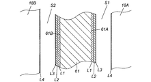
- FIG. 1 is an enlarged cross-sectional view of a first cylindrical body made of fiber-reinforced plastic that constitutes a rotor that is a rotating body of the vacuum pump of FIG. 1 and a thread groove pump portion stator that is a fixing member of the vacuum pump facing the first cylinder.
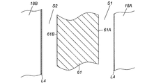
- FIG. 1 is an enlarged cross-sectional view of a first cylindrical body made of fiber-reinforced plastic that constitutes a rotor that is a rotating body of the vacuum pump of FIG. 1 and a thread groove pump portion stator that is a fixing member of the vacuum pump facing the first cylinder.
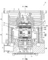
- FIG. 1 is a sectional view of a vacuum pump to which the present invention is applied.
- the vacuum pump P shown in the figure is used as, for example, a gas exhaust means for a process chamber or other sealed chamber in a semiconductor manufacturing apparatus, a flat panel display manufacturing apparatus, or a solar panel manufacturing apparatus.
- the vacuum pump P includes a blade exhaust part Pt that exhausts gas by the rotary blade 13 and the fixed blade 14 in the outer case 1, a screw groove pump part Ps that exhausts gas using the screw grooves 19A and 19B, These drive systems are included.
- the outer case 1 has a bottomed cylindrical shape in which a cylindrical pump case 1A and a bottomed cylindrical pump base 1B are integrally connected with bolts in the cylinder axis direction.
- the upper end portion side of the pump case 1A is opened as a gas intake port 2, and a gas exhaust port 3 is provided on the side surface of the lower end portion of the pump base 1B.
- the gas inlet 2 is connected to a sealed chamber (not shown), which is a high vacuum, such as a process chamber of a semiconductor manufacturing apparatus, by a bolt (not shown) provided on the flange 1C on the upper edge of the pump case 1A.
- the gas exhaust port 3 is connected so as to communicate with an auxiliary pump (not shown).
- a cylindrical stator column 4 containing various electrical components is provided in the center of the pump case 1A, and the stator column 4 is erected in such a manner that its lower end is screwed and fixed onto the pump base 1B. is there.
- a rotor shaft 5 is provided inside the stator column 4, and the rotor shaft 5 is arranged such that its upper end portion faces the gas inlet 2 and its lower end portion faces the pump base 1B. is there. Further, the upper end portion of the rotor shaft 5 is provided so as to protrude upward from the cylindrical upper end surface of the stator column 4.
- the rotor shaft 5 is supported by a radial magnetic bearing 10 and an axial magnetic bearing 11 so as to be rotatable in the radial direction and the axial direction, and is rotated by a drive motor 12 in this state.
- the drive motor 12 has a structure including a stator 12A and a rotor 12B, and is provided near the center of the rotor shaft 5.
- the stator 12 ⁇ / b> A of the drive motor 12 is installed inside the stator column 4, and the rotor 12 ⁇ / b> B of the drive motor 12 is integrally mounted on the outer peripheral surface side of the rotor shaft 5.
- Two sets of radial magnetic bearings 10 are arranged one by one above and below the drive motor 12, and one set of axial magnetic bearings 11 is arranged on the lower end side of the rotor shaft 5.
- the two sets of radial magnetic bearings 10 and 10 are respectively a radial electromagnet target 10A attached to the outer peripheral surface of the rotor shaft 5, a plurality of radial electromagnets 10B installed on the inner side surface of the stator column 4 facing this, and a radial direction displacement sensor. 10C is comprised.
- the radial electromagnet target 10A is made of a laminated steel plate in which steel plates of high permeability material are laminated, and the radial electromagnet 10B attracts the rotor shaft 5 with a magnetic force in the radial direction through the radial electromagnet target 10A.
- the radial direction displacement sensor 10 ⁇ / b> C detects the radial displacement of the rotor shaft 5.
- the rotor shaft 5 is levitated and supported by a magnetic force at a predetermined position in the radial direction.
- the axial magnetic bearing 11 includes a disk-shaped armature disk 11A attached to the outer periphery of the lower end portion of the rotor shaft 5, an axial electromagnet 11B facing up and down across the armature disk 11A, and a position slightly away from the lower end surface of the rotor shaft 5. And an axial direction displacement sensor 11C installed in The armature disk 11A is made of a material having high magnetic permeability, and the upper and lower axial electromagnets 11B attract the armature disk 11A from the upper and lower directions with a magnetic force.
- the axial direction displacement sensor 11 ⁇ / b> C detects the axial displacement of the rotor shaft 5.
- the rotor shaft 5 is levitated and supported at a predetermined position in the axial direction by controlling the excitation current of the upper and lower axial electromagnets 11B based on the detection value (axial displacement of the rotor shaft 5) detected by the axial direction displacement sensor 11C.
- a rotor 6 is provided outside the stator column 4 as a rotating body of the vacuum pump P.
- the rotor 6 has a cylindrical shape surrounding the outer periphery of the stator column 4, and has two cylindrical bodies (a first cylindrical body 61 and a first cylindrical body 61) having different diameters via an annular plate-shaped support member 60 positioned substantially in the middle. 2 cylinders 62) are connected in the axial direction.
- the support member 60 is integrally provided at the lower end of the second cylindrical body 62, and the ring-shaped convex portion 60 ⁇ / b> A is integrally formed on the back outer peripheral portion of the support member 60.
- the first cylinder 61 and the second cylinder 62 are connected in the axial direction by press-fitting and mounting the first cylinder 61 on the outer periphery of the ring-shaped convex portion 60A. It is configured.
- An end member 63 is provided at the upper end of the second cylindrical body 62, and the rotor 6 and the rotor shaft 5 are integrated via the end member 63.
- a boss hole 7 is provided at the center of the end member 63, and a stepped shoulder (hereinafter referred to as “rotor shaft shoulder” is formed on the outer periphery of the upper end of the rotor shaft 5. Part 9 "). Then, by inserting the tip of the rotor shaft 5 above the rotor shaft shoulder 9 into the boss hole 7 of the end member 63 and fastening and fixing the end member 63 and the rotor shaft shoulder 9 with bolts, The rotor shaft 5 is integrated.
- the first cylinder 61 includes AFPR (aramid fiber reinforced plastic), BFRP (boron fiber reinforced plastic), It is formed of a fiber reinforced plastic such as CFRP (carbon fiber reinforced plastic), DFRP (polyethylene fiber reinforced plastic), or GFRP (glass fiber reinforced plastic).
- CFRP carbon fiber reinforced plastic
- DFRP polyethylene fiber reinforced plastic
- GFRP glass fiber reinforced plastic
- the vacuum pump P of FIG. 1 employs the rotor 6 having a configuration including the first cylindrical body 61 made of fiber reinforced plastic as an example of a rotating body partially made of fiber reinforced plastic. Is.
- the rotor 6 is supported by the radial magnetic bearings 10 and 10 and the axial magnetic bearing 11 via the rotor shaft 5 so as to be rotatable around its axis (rotor shaft 5). Therefore, in the vacuum pump P of FIG. 1, the rotor shaft 5, the radial magnetic bearings 10 and 10, and the axial magnetic bearing 11 function as support means that rotatably supports the rotor 6 about its axis. Further, since the rotor 6 rotates integrally with the rotor shaft 5, the drive motor 12 that rotationally drives the rotor shaft 5 functions as drive means that rotationally drives the rotor 6.
- the vacuum pump P shown in FIG. 1 is configured so that the upstream from the substantially middle of the rotor 6 (the range from the substantially middle of the rotor 6 to the gas inlet 2 side end of the rotor 6) functions as the blade exhaust part Pt. is there.
- the blade exhaust part Pt will be described in detail below.
- a plurality of rotor blades 13 are integrally provided on the outer circumferential surface of the rotor 6 (specifically, the outer circumferential surface of the second cylindrical body 62) on the upstream side of the middle of the rotor 6.
- the plurality of rotor blades 13 are arranged radially about the rotation axis of the rotor 6 (rotor shaft 5) or the axis of the outer case 1 (hereinafter referred to as “pump axis”).
- a plurality of fixed wings 14 are provided on the inner peripheral surface side of the pump case 1A, and these fixed wings 14 are arranged radially around the pump axis.
- the rotor blades 13 and the stationary blades 14 are alternately arranged in multiple stages along the pump axis, thereby forming the blade exhaust part Pt.
- Each of the rotor blades 13 is a blade-like cut product that is cut and formed integrally with the outer diameter machining portion of the rotor 6 and is inclined at an angle that is optimal for exhaust of gas molecules.
- Each fixed blade 14 is also inclined at an angle optimum for exhausting gas molecules.
- the vacuum pump P in FIG. 1 is configured so that the downstream side from the substantially middle of the rotor 6 (the range from the substantially middle of the rotor 6 to the gas exhaust port 3 side end of the rotor 6) functions as the thread groove pump part Ps. is there.
- the thread groove pump portion Ps will be described in detail below.
- a rotor 6 (specifically, a portion of the first cylindrical body 61) on the downstream side from the substantially middle of the rotor 6 is a portion that rotates as a rotating member of the thread groove pump portion Ps. It is configured to be inserted and accommodated between the double cylindrical thread groove pump part stators 18A and 18B via a predetermined gap.
- the outer thread groove pump section stator 18A serves as a fixing member for the vacuum pump P located outside the rotor 6 and is the outer periphery of the rotor 6 (abbreviation of the rotor 6). It is provided so as to face the outer peripheral surface of the rotor 6 by being disposed so as to surround a portion downstream from the middle. Further, a screw groove 19A that changes to a tapered cone shape whose depth is reduced in diameter toward the bottom is formed in the inner peripheral portion of the outer screw groove pump portion stator 18A.
- the thread groove 19A is spirally engraved from the upper end to the lower end of the thread groove pump portion stator 18A, and the screw groove 19A causes a spiral between the rotor 6 and the outer thread groove pump portion stator 18A.
- a thread groove pump flow path (hereinafter referred to as “outer thread groove pump flow path S1”) is formed. Note that the lower end of the outer thread groove pump portion stator 18A is supported by the pump base 1B.
- the inner thread groove pump portion stator 18 ⁇ / b> B is disposed so as to be surrounded by the inner periphery of the rotor 6 as a fixing member of the vacuum pump P located inside the rotor 6, so as to face the inner peripheral surface of the rotor 6.
- a thread groove 19B is formed in the outer peripheral portion of the inner thread groove pump portion stator 18B.
- a spiral thread groove pump flow path (hereinafter referred to as “inner thread groove pump flow path S2”) is also formed between the rotor 6 and the inner thread groove pump portion stator 18B. Note that the lower end portion of the inner thread groove pump portion stator 18B is also supported by the pump base 1B.
- the thread groove pump portion Ps gas is compressed and transferred by the drag effect on the outer circumferential surface of the thread groove 19A and the rotor 6 and the drag effect on the inner circumferential surface of the thread groove 19B and the rotor 6, so that the depth of the thread groove 19A is increased.
- the depth is deepest on the upstream inlet side (passage opening end closer to the gas intake port 2) of the outer thread groove pump flow path S1, and is the deepest on the downstream outlet side (passage opening end closer to the gas exhaust port 3). It is set to be shallow. The same applies to the thread groove 19B.
- the upstream inlet of the outer thread groove pump flow path S1 is the lowermost blade (the fixed blade 14 in the example of FIG. 1) of the rotor blades 13 and the fixed blades 14 arranged in multiple stages and a communication opening H described later. It communicates with a gap between the upstream ends (hereinafter referred to as “final gap G”), and the downstream outlet of the passage S1 is configured to communicate with the gas exhaust port 3 side.
- the upstream inlet of the inner thread groove pump flow path S2 opens toward the inner peripheral surface of the rotor 6 substantially in the middle of the rotor 6, and the downstream outlet of the passage S2 joins the downstream outlet of the outer thread groove pump flow path S1. Thus, it is configured to communicate with the gas exhaust port 3.
- a communication opening H is formed substantially in the middle of the rotor 6, and the communication opening H is formed so as to penetrate the front and back surfaces of the support member 60. It functions to lead a part to the inner thread pump channel S2.
- the rotor 6 is provided with a corrosion-resistant treatment layer L1 on the fiber reinforced plastic portion (the surface of the first cylindrical body 61 in the example shown in the figure), which is the base material.
- a high emissivity layer L3 having a higher emissivity than the anticorrosion treatment layer L1 is provided on the anticorrosion treatment layer L1.
- the vacuum pump P in FIG. 1 is used in an environment in which corrosive gas that decomposes the plastic component is exhausted. Therefore, the fiber reinforced plastic portion of the rotor 6 (the first cylinder 61 in the example of FIG. 1) is corrosive. As a means for protecting from gas, as described above, the surface of the first cylindrical body 61 is protected by the corrosion-resistant treatment layer L1 such as nickel alloy.
- the fiber reinforced plastic forming the first cylindrical body 61 which is a part of the rotor has a lower thermal conductivity than the aluminum or the alloy forming the other part of the rotor 6 and generates a temperature distribution. Easy to do.
- the first cylinder 61 has a relatively high temperature due to heat (friction heat) generated by friction with the gas to be exhausted at the end portion on the gas exhaust port 3 side where the pressure is high.
- the corrosion-resistant treatment layer L1 is provided on the first cylindrical body 61 (fiber reinforced plastic portion of the rotor 6), and a higher level is provided on the corrosion-resistant treatment layer L1.
- the emissivity layer L3 By providing the emissivity layer L3, the emissivity of the first cylinder 61 is increased. Therefore, heat generated in the first cylinder 61 is easily released by radiation, and the outer and inner thread groove pumps.
- the first cylinder 61 having a high pressure near the exhaust port side end becomes a high temperature due to the frictional heat described above and effectively prevents a malfunction that exceeds the allowable temperature of the fiber reinforced plastic. .
- the corrosion-resistant layer L1 on the inner peripheral surface of the rotor 6 is made of a first metal film having excellent corrosion resistance, such as a nickel alloy, and is formed so as to entirely cover the outer peripheral surface of the first cylindrical body 61.
- the high emissivity layer L3 covering the corrosion resistant layer L1 forms a second metal film L2 such as an aluminum alloy or a nickel alloy on the corrosion resistant layer L1, and the surface of the second metal film L2 Is formed so as to entirely cover the corrosion-resistant layer L1.
- the high emissivity layer L3 there is also a method of oxidizing the surface of the first metal coating (corrosion resistant layer L1) and adopting the oxide film layer as the high emissivity layer L3. Conceivable.
- the corrosion-resistant treatment layer L1 is formed by electroless Ni—P plating treatment, pinholes are generated in the corrosion-resistant treatment layer L1, and oxidation of the corrosion-resistant treatment layer L1 having pinholes occurs.
- the corrosion-resistant layer L1 is easily damaged and destroyed near the pinholes, so that the protection function of the first cylindrical body 61 (made of fiber-reinforced plastic) by the corrosion-resistant layer L1 is impaired.
- the above-described method that is, on the corrosion-resistant layer (first metal coating) L1.
- the high emissivity layer L3 is formed by oxidizing the surface of the second metal film L2 after protecting the corrosion-resistant layer L1 with the second metal film L2 by forming the second metal film L2. Preferably formed.
- the corrosion-resistant layer L1 (first metal film) and the second metal film L2 described above can be formed by, for example, an electrolytic plating method, an electroless plating method, or a sputtering method. .
- a DLC layer formed by performing DLC (Diamond Like Carbon) coating treatment on the corrosion-resistant treatment layer L1 Can also be adopted.
- the screw grooves 19A and 19B described above are formed on the opposing surfaces of the outer screw groove pump portion stator 18A and the inner screw groove pump portion stator 18B, the high emissivity layer provided on the opposite surfaces. L4 may be formed on the inner surface and the side surface of the screw grooves 19A and 19B in addition to being formed on the screw thread portions of the screw grooves 19A and 19B.
- the high emissivity layer L4 on the opposite surface of the fixing member is formed, for example, when the fixing member is formed of aluminum or an alloy thereof.
- An oxide film layer formed by oxidizing the surface of the alloy can be employed.
- emissivity is higher than aluminum or an alloy thereof, which is a base material of the fixing member (screw groove pump stators 18A and 18B) such as fluorine resin or epoxy resin, for example.
- a coating film layer formed by coating the surface of the fixing member with a high material, or a DLC layer formed by applying a DLC coating process to the surface of the fixing member can also be employed.
- the thread groove pump portion stators 18A and 18B are used as means for guiding and escaping the heat inside the pump to the outside.
- the thread groove pump stators 18A and 18B are made of a metal material having high thermal conductivity such as aluminum or an alloy thereof, the surface radiation rate is low, and the fiber reinforced plastic part (the first part of the rotor 6) 1 has a low ability to receive by radiation of the cylindrical body 61).
- the capability is enhanced by the high emissivity layer L4, so that the thread groove pump portion stators 18A and 18B efficiently receive the heat of the fiber reinforced plastic portion of the rotor 6 by radiation. It is possible to guide the received heat to the outside and escape.
- the corrosion-resistant treatment layer L1 is provided on the fiber-reinforced plastic portion (the first cylindrical body 61), and the corrosion resistance thereof.
- the configuration in which the high emissivity layer L3 is provided on the treatment layer L1 is an example applied when the vacuum pump P of FIG. 1 is used in an environment in which a corrosive gas that decomposes a plastic component is exhausted. Therefore, when the vacuum pump P of FIG. 1 is used in an environment in which non-corrosive gas is exhausted, the corrosion-resistant treatment layer L1 may be omitted from the above configuration as shown in FIG.
- the fiber-reinforced plastic forming the first cylinder 61 of the rotor 6 forms a rotor component other than the first cylinder 61 (second cylinder 62, support member 60, end member 63). Since the emissivity is higher than that of aluminum or its alloy, etc., the high emissivity layer L3 may be omitted together with the second metal coating L2 in the above configuration as shown in FIG.
- Thread Groove Pump Stator 18A, 18B (Same Vacuum) Opposing Fiber Reinforced Plastic Part (First Cylinder 61) of Rotor 6 It is only necessary to provide a high emissivity layer L4 having a higher emissivity than aluminum or an alloy thereof as a base material of the thread groove pump portion stators 18A and 18B on the opposite surface of the fixing member of the pump P (see FIG. 3).
- heat released by radiation from the fiber reinforced plastic portion of the rotor 6 can be efficiently received by the high emissivity layers of the thread groove pump portion stators 18A and 18B.
- the amount of heat accumulated in the reinforced plastic portion decreases, and the temperature of the fiber reinforced plastic portion (first cylinder 61) of the rotor 6 increases due to heat (friction heat) generated by friction between the exhaust gas and the rotor 6. A situation where the allowable temperature is exceeded is effectively prevented.
- the embodiment described above is an example in which the present invention is applied to a structure in which a part of the rotor 6 (specifically, a part of the first cylindrical body 61) which is a rotating body of the vacuum pump P is made of fiber reinforced plastic.
- the present invention is not limited to this example, and can also be applied to a structure in which the entire rotor 6 (including the rotary blades 13) is made of fiber reinforced plastic.
Landscapes
- Engineering & Computer Science (AREA)
- Mechanical Engineering (AREA)
- General Engineering & Computer Science (AREA)
- Non-Positive Displacement Air Blowers (AREA)
Abstract
L'invention vise à pourvoir à un corps rotatif d'une pompe à vide approprié pour obtenir une pompe à vide hautement fiable qui atteint une amélioration des performances de décharge et une amélioration du débit de gaz dans lequel un gaz est apte à être déchargé en continu (= débit maximal) en même temps, un élément fixe opposé à celui-ci et une pompe à vide les comportant. A cet effet, l'invention porte sur un corps rotatif (rotor (6)) d'une pompe à vide (P) qui a une partie de celui-ci (premier cylindre (61)) qui est réalisée à partir d'une matière plastique renforcée par des fibres, qui est configurée de façon à décharger un gaz par rotation, qui comporte une couche de traitement résistant à la corrosion (L1) sur une partie en matière plastique renforcée par des fibres qui est un matériau de base de celui-ci, et qui comporte une couche à facteur de rayonnement élevé (L3) ayant un facteur de rayonnement plus élevé que la couche de traitement résistant à la corrosion (L1) sur la couche de traitement résistant à la corrosion (L1). Des éléments fixes (stators de partie de pompe à rainure filetée (18A, 18B)) opposés au corps rotatif de la pompe à vide (P) comportent des couches à facteur de rayonnement élevé (L4) ayant un facteur de rayonnement plus élevé que des matériaux de base des éléments fixes sur des surfaces opposées (surfaces en vis-à-vis) sur la partie en matière plastique renforcée par des fibres (premier cylindre (61)) du corps rotatif.
Priority Applications (2)
| Application Number | Priority Date | Filing Date | Title |
|---|---|---|---|
| US13/982,412 US20130309076A1 (en) | 2011-02-04 | 2011-11-28 | Rotating Body of Vacuum Pump, Fixed Member Disposed Opposite Rotating Body, and Vacuum Pump Provided with Rotating Body and Fixed Member |
| CN2011800654999A CN103299083A (zh) | 2011-02-04 | 2011-11-28 | 真空泵的旋转体、与其相对设置的固定部件以及具备它们的真空泵 |
Applications Claiming Priority (2)
| Application Number | Priority Date | Filing Date | Title |
|---|---|---|---|
| JP2011022923 | 2011-02-04 | ||
| JP2011-022923 | 2011-02-04 |
Publications (1)
| Publication Number | Publication Date |
|---|---|
| WO2012105116A1 true WO2012105116A1 (fr) | 2012-08-09 |
Family
ID=46602348
Family Applications (1)
| Application Number | Title | Priority Date | Filing Date |
|---|---|---|---|
| PCT/JP2011/077301 Ceased WO2012105116A1 (fr) | 2011-02-04 | 2011-11-28 | Corps rotatif de pompe à vide, élément fixe placé pour être opposé à celui-ci, et pompe à vide les comportant |
Country Status (3)
| Country | Link |
|---|---|
| US (1) | US20130309076A1 (fr) |
| CN (1) | CN103299083A (fr) |
| WO (1) | WO2012105116A1 (fr) |
Cited By (1)
| Publication number | Priority date | Publication date | Assignee | Title |
|---|---|---|---|---|
| DE102014203172A1 (de) | 2014-02-21 | 2015-08-27 | Oerlikon Leybold Vacuum Gmbh | Beschichtete CFK Oberflächen von Turbomolekularpumpen |
Families Citing this family (9)
| Publication number | Priority date | Publication date | Assignee | Title |
|---|---|---|---|---|
| TWI586893B (zh) * | 2011-11-30 | 2017-06-11 | Edwards Japan Ltd | Vacuum pump |
| EP2615307B1 (fr) * | 2012-01-12 | 2019-08-21 | Vacuubrand Gmbh + Co Kg | Pompe à vide à vis |
| DE202013010195U1 (de) * | 2013-11-12 | 2015-02-18 | Oerlikon Leybold Vacuum Gmbh | Vakuumpumpen-Rotoreinrichtung sowie Vakuumpumpe |
| JP6287475B2 (ja) * | 2014-03-28 | 2018-03-07 | 株式会社島津製作所 | 真空ポンプ |
| JP6758865B2 (ja) * | 2016-03-04 | 2020-09-23 | エドワーズ株式会社 | 真空ポンプ |
| JP7150565B2 (ja) * | 2018-10-31 | 2022-10-11 | エドワーズ株式会社 | 真空ポンプ、及び、真空ポンプ構成部品 |
| US11255220B1 (en) * | 2019-10-02 | 2022-02-22 | Battelle Memorial Institute | Heating assemblies, heat exchange assemblies, methods for providing and/or exchanging heat, turbine combustion engines, and methods for powering turbine combustion engines |
| JP7671586B2 (ja) * | 2021-01-18 | 2025-05-02 | エドワーズ株式会社 | 真空ポンプとその回転体 |
| JP2026043283A (ja) * | 2024-08-28 | 2026-03-12 | エドワーズ株式会社 | 真空ポンプ、真空ポンプ用部品およびその製造方法 |
Citations (5)
| Publication number | Priority date | Publication date | Assignee | Title |
|---|---|---|---|---|
| JPH10122179A (ja) * | 1996-10-18 | 1998-05-12 | Osaka Shinku Kiki Seisakusho:Kk | 真空ポンプ |
| JP2000161286A (ja) * | 1998-11-25 | 2000-06-13 | Shimadzu Corp | ターボ分子ポンプ |
| JP2003254285A (ja) * | 2002-02-28 | 2003-09-10 | Boc Edwards Technologies Ltd | ポンプ装置 |
| JP2006046074A (ja) * | 2004-07-30 | 2006-02-16 | Boc Edwards Kk | 真空ポンプ |
| JP2006233978A (ja) * | 2006-06-05 | 2006-09-07 | Mitsubishi Heavy Ind Ltd | ターボ分子ポンプ |
Family Cites Families (3)
| Publication number | Priority date | Publication date | Assignee | Title |
|---|---|---|---|---|
| JP2005155403A (ja) * | 2003-11-25 | 2005-06-16 | Boc Edwards Kk | 真空ポンプ |
| JP2005320905A (ja) * | 2004-05-10 | 2005-11-17 | Boc Edwards Kk | 真空ポンプ |
| CN1986213B (zh) * | 2005-12-22 | 2010-12-08 | 鸿富锦精密工业(深圳)有限公司 | 一种磁性耐磨镀膜的制作方法 |
-
2011
- 2011-11-28 CN CN2011800654999A patent/CN103299083A/zh active Pending
- 2011-11-28 US US13/982,412 patent/US20130309076A1/en not_active Abandoned
- 2011-11-28 WO PCT/JP2011/077301 patent/WO2012105116A1/fr not_active Ceased
Patent Citations (5)
| Publication number | Priority date | Publication date | Assignee | Title |
|---|---|---|---|---|
| JPH10122179A (ja) * | 1996-10-18 | 1998-05-12 | Osaka Shinku Kiki Seisakusho:Kk | 真空ポンプ |
| JP2000161286A (ja) * | 1998-11-25 | 2000-06-13 | Shimadzu Corp | ターボ分子ポンプ |
| JP2003254285A (ja) * | 2002-02-28 | 2003-09-10 | Boc Edwards Technologies Ltd | ポンプ装置 |
| JP2006046074A (ja) * | 2004-07-30 | 2006-02-16 | Boc Edwards Kk | 真空ポンプ |
| JP2006233978A (ja) * | 2006-06-05 | 2006-09-07 | Mitsubishi Heavy Ind Ltd | ターボ分子ポンプ |
Cited By (2)
| Publication number | Priority date | Publication date | Assignee | Title |
|---|---|---|---|---|
| DE102014203172A1 (de) | 2014-02-21 | 2015-08-27 | Oerlikon Leybold Vacuum Gmbh | Beschichtete CFK Oberflächen von Turbomolekularpumpen |
| EP2918628A1 (fr) | 2014-02-21 | 2015-09-16 | Oerlikon Leybold Vacuum GmbH | Surfaces en laminés de fibres de carbone revêtues de pompes turbomoléculaires |
Also Published As
| Publication number | Publication date |
|---|---|
| US20130309076A1 (en) | 2013-11-21 |
| CN103299083A (zh) | 2013-09-11 |
Similar Documents
| Publication | Publication Date | Title |
|---|---|---|
| WO2012105116A1 (fr) | Corps rotatif de pompe à vide, élément fixe placé pour être opposé à celui-ci, et pompe à vide les comportant | |
| KR102106658B1 (ko) | 로터, 및, 이 로터를 구비한 진공 펌프 | |
| JP2005320905A (ja) | 真空ポンプ | |
| JP5763660B2 (ja) | 排気ポンプ | |
| JP5767644B2 (ja) | 排気ポンプ | |
| JP6331491B2 (ja) | 真空ポンプ | |
| US10190597B2 (en) | Vacuum pump and rotor thereof | |
| CN108708863B (zh) | 真空泵、真空泵的旋转体和静翼及其制造方法 | |
| JP6133213B2 (ja) | 固定部材及び真空ポンプ | |
| JP6758865B2 (ja) | 真空ポンプ | |
| JP2003021092A (ja) | 真空ポンプ | |
| JP5577798B2 (ja) | ターボ分子ポンプ | |
| TWI665388B (zh) | 渦輪分子幫浦 | |
| JP2005155403A (ja) | 真空ポンプ | |
| CN121219497A (zh) | 涡轮分子真空泵 |
Legal Events
| Date | Code | Title | Description |
|---|---|---|---|
| 121 | Ep: the epo has been informed by wipo that ep was designated in this application |
Ref document number: 11857709 Country of ref document: EP Kind code of ref document: A1 |
|
| WWE | Wipo information: entry into national phase |
Ref document number: 13982412 Country of ref document: US |
|
| NENP | Non-entry into the national phase |
Ref country code: DE |
|
| 122 | Ep: pct application non-entry in european phase |
Ref document number: 11857709 Country of ref document: EP Kind code of ref document: A1 |
|
| NENP | Non-entry into the national phase |
Ref country code: JP |