WO2012105125A1 - Dispositif de manipulation de billets - Google Patents
Dispositif de manipulation de billets Download PDFInfo
- Publication number
- WO2012105125A1 WO2012105125A1 PCT/JP2011/078220 JP2011078220W WO2012105125A1 WO 2012105125 A1 WO2012105125 A1 WO 2012105125A1 JP 2011078220 W JP2011078220 W JP 2011078220W WO 2012105125 A1 WO2012105125 A1 WO 2012105125A1
- Authority
- WO
- WIPO (PCT)
- Prior art keywords
- bill
- transport path
- drive motor
- bills
- speed
- Prior art date
- Legal status (The legal status is an assumption and is not a legal conclusion. Google has not performed a legal analysis and makes no representation as to the accuracy of the status listed.)
- Ceased
Links
Images



Classifications
-
- B—PERFORMING OPERATIONS; TRANSPORTING
- B65—CONVEYING; PACKING; STORING; HANDLING THIN OR FILAMENTARY MATERIAL
- B65H—HANDLING THIN OR FILAMENTARY MATERIAL, e.g. SHEETS, WEBS, CABLES
- B65H5/00—Feeding articles separated from piles; Feeding articles to machines
- B65H5/06—Feeding articles separated from piles; Feeding articles to machines by rollers or balls, e.g. between rollers
- B65H5/062—Feeding articles separated from piles; Feeding articles to machines by rollers or balls, e.g. between rollers between rollers or balls
-
- B—PERFORMING OPERATIONS; TRANSPORTING
- B65—CONVEYING; PACKING; STORING; HANDLING THIN OR FILAMENTARY MATERIAL
- B65H—HANDLING THIN OR FILAMENTARY MATERIAL, e.g. SHEETS, WEBS, CABLES
- B65H5/00—Feeding articles separated from piles; Feeding articles to machines
- B65H5/26—Duplicate, alternate, selective, or coacting feeds
-
- B—PERFORMING OPERATIONS; TRANSPORTING
- B65—CONVEYING; PACKING; STORING; HANDLING THIN OR FILAMENTARY MATERIAL
- B65H—HANDLING THIN OR FILAMENTARY MATERIAL, e.g. SHEETS, WEBS, CABLES
- B65H7/00—Controlling article feeding, separating, pile-advancing, or associated apparatus, to take account of incorrect feeding, absence of articles, or presence of faulty articles
-
- G—PHYSICS
- G07—CHECKING-DEVICES
- G07D—HANDLING OF COINS OR VALUABLE PAPERS, e.g. TESTING, SORTING BY DENOMINATIONS, COUNTING, DISPENSING, CHANGING OR DEPOSITING
- G07D11/00—Devices accepting coins; Devices accepting, dispensing, sorting or counting valuable papers
- G07D11/10—Mechanical details
- G07D11/16—Handling of valuable papers
-
- G—PHYSICS
- G07—CHECKING-DEVICES
- G07D—HANDLING OF COINS OR VALUABLE PAPERS, e.g. TESTING, SORTING BY DENOMINATIONS, COUNTING, DISPENSING, CHANGING OR DEPOSITING
- G07D11/00—Devices accepting coins; Devices accepting, dispensing, sorting or counting valuable papers
- G07D11/20—Controlling or monitoring the operation of devices; Data handling
- G07D11/22—Means for sensing or detection
- G07D11/235—Means for sensing or detection for monitoring or indicating operating conditions; for detecting malfunctions
- G07D11/237—Means for sensing or detection for monitoring or indicating operating conditions; for detecting malfunctions for detecting transport malfunctions, e.g. jams or misfeeds
-
- B—PERFORMING OPERATIONS; TRANSPORTING
- B65—CONVEYING; PACKING; STORING; HANDLING THIN OR FILAMENTARY MATERIAL
- B65H—HANDLING THIN OR FILAMENTARY MATERIAL, e.g. SHEETS, WEBS, CABLES
- B65H2301/00—Handling processes for sheets or webs
- B65H2301/40—Type of handling process
- B65H2301/44—Moving, forwarding, guiding material
- B65H2301/447—Moving, forwarding, guiding material transferring material between transport devices
- B65H2301/4474—Pair of cooperating moving elements as rollers, belts forming nip into which material is transported
-
- B—PERFORMING OPERATIONS; TRANSPORTING
- B65—CONVEYING; PACKING; STORING; HANDLING THIN OR FILAMENTARY MATERIAL
- B65H—HANDLING THIN OR FILAMENTARY MATERIAL, e.g. SHEETS, WEBS, CABLES
- B65H2511/00—Dimensions; Position; Numbers; Identification; Occurrences
- B65H2511/20—Location in space
-
- B—PERFORMING OPERATIONS; TRANSPORTING
- B65—CONVEYING; PACKING; STORING; HANDLING THIN OR FILAMENTARY MATERIAL
- B65H—HANDLING THIN OR FILAMENTARY MATERIAL, e.g. SHEETS, WEBS, CABLES
- B65H2513/00—Dynamic entities; Timing aspects
- B65H2513/10—Speed
-
- B—PERFORMING OPERATIONS; TRANSPORTING
- B65—CONVEYING; PACKING; STORING; HANDLING THIN OR FILAMENTARY MATERIAL
- B65H—HANDLING THIN OR FILAMENTARY MATERIAL, e.g. SHEETS, WEBS, CABLES
- B65H2513/00—Dynamic entities; Timing aspects
- B65H2513/20—Acceleration or deceleration
-
- B—PERFORMING OPERATIONS; TRANSPORTING
- B65—CONVEYING; PACKING; STORING; HANDLING THIN OR FILAMENTARY MATERIAL
- B65H—HANDLING THIN OR FILAMENTARY MATERIAL, e.g. SHEETS, WEBS, CABLES
- B65H2513/00—Dynamic entities; Timing aspects
- B65H2513/40—Movement
- B65H2513/42—Route, path
Definitions
- the present invention relates to a bill handling device such as that implemented in an automated teller machine used in a financial institution or the like.
- a bill handling device is mounted on an automated teller machine (ATM) used in financial institutions and the like.
- the bill handling apparatus has a bill receiving / dispensing port having a function of feeding out the bills deposited to the user one by one and a function of releasing the deposited bills, and a bill discriminating portion for discriminating the deposited bills or the dispensed bills.
- the bill discrimination unit discriminates the denomination and the state of the bill, and in order to convey the bill to each appropriate unit, a gate for switching the conveyance destination is installed on the bill conveyance path.
- the discrimination processing time in the bill discrimination portion and the processing time for switching this gate exist.
- the processing time for switching the gate is in time.
- problems such as a collision between a bill and a gate and an error in the transport destination occur. For this reason, usually, the bill delivery interval from each unit is set, and the optimal processing time is secured.
- Patent Document 1 proposes a medium conveyance device which is provided with means for detecting a bill conveyance speed, sets a bill feeding interval based on the detected bill conveyance speed, and constantly maintains an appropriate interval.
- control of the bill dispensing interval is realized by decreasing the bill dispensing speed or increasing the bill dispensing interval, so it is optimal in consideration of the number of processed sheets per unit time. It can not be called control.
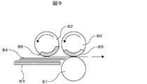
- the pressing plate 83 presses the pickup roller 82 (hereinafter referred to as P roller) to generate a frictional force, and the rubber phase 86 having a high coefficient of friction comes. Pay out the bills.
- the feed roller 80 (hereinafter referred to as F roller) also has a rubber phase 85 having a high friction coefficient in a phase where it is desired to apply a feeding force to the bill, and tries to feed the bill.
- the gate roller 81 (hereinafter referred to as G roller) is configured not to rotate in the delivery direction, and locks the second and subsequent bills.
- one rotation of the F roller 80 causes the bills to be fed out one by one.
- the number of revolutions N of the F roller 80 determines the number of fed sheets per unit time.
- the speed Va of the bill to be fed out is 2 ⁇ ⁇ ⁇ N ⁇ R.
- the speed Va of the bill to be fed out is determined by the number of revolutions N of the F roller 80 and the radius R of the F roller 80. Since the rotation speed N of the F roller 80 is limited by the product specification, the gap L between bills can be increased by increasing the radius R of the F roller 80. However, since the bill handling apparatus is required to be miniaturized, it is difficult to make the F roller 80 large.
- the above-mentioned bill delivery is performed at a connection point between a bill transport path 87a driven by a motor 88a having a function of delivering bills and a bill transport path 87b driven by a motor 88b having a function of connecting units.
- the bill fed at the speed Va by the mechanism is delivered to the bill conveyance path 87b driven at the conveyance speed Vb (Vb> Va) to accelerate the bill. Since the bills themselves do not extend if the transport speed is increased at a fixed number of processed bill per unit time, only the bill interval L can be expanded. That is, in FIG. 10, the relationship of Lb> La is established.
- an object of the present invention is to prevent occurrence of tearing or jamming of a bill in a bill handling device, to improve the conveyance reliability, and to realize high-speed conveyance of a bill.
- the banknote handling apparatus is preferably a banknote handling apparatus for transporting, storing or dispensing banknotes for depositing and dispensing, and for receiving and depositing banknotes for depositing and separating them into the apparatus and for dispensing.
- a drive motor, a storage unit transport path drive motor for driving the storage portion transport path, and the first transport path 3 the first to third drive motor for driving the conveying path each independently, configured as a bill handling apparatus having a control unit for controlling said first to third drive motors in separate speeds.
- the control unit controls the bill handling to control the speed of the first drive motor to be faster than the drive motor for depositing and dispensing port conveyance path and to make the second drive motor faster than the first drive motor. It is configured as a device. In addition, preferably, the control unit performs drive control so that the speed of the third drive motor is higher than the drive motor for the storage portion conveyance path and the speed of the second drive motor is higher than the speed of the third drive motor.
- the first drive motor is configured as the bill handling device controlled at the same speed as the second drive motor.
- the transport path is further divided and driven by an independent drive motor, thereby forming a bill handling device that accelerates in multiple stages.
- the control unit controls the drive motor for the deposit / withdrawal port transport path, the first to third drive motors, and the drive motor for the storage transport path in forward and reverse directions.
- it is configured as a bill handling device for conveying a bill in both directions on each conveyance path.
- the motor of the transport path can be miniaturized.
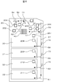
- the side view of the bill handling device used for explanation of payment transaction processing operation by one example.
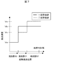
- the figure which shows the control example of the step acceleration of the banknote in one Example (Example 1).
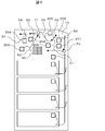
- FIG. 1 is a side view showing the configuration of the bill handling apparatus.
- the bill handling apparatus 1 is for handling and processing bills and is mounted in a case of an automated teller machine (ATM).
- ATM automated teller machine
- the bill deposit / withdrawal port 10 where the user inserts and takes out bills is disposed in the upper front, and a bill discrimination unit that discriminates the authenticity, denomination, and damage state of bills by a sensor or the like in the central portion. 40 are arranged.
- a temporary storage unit 20 for temporarily storing the banknotes deposited by the user until the transaction is established is disposed.
- bill storages 30 to 33 for storing the deposited bills in denominations and feeding them out are arranged.
- These banknote storages may be used as reject storages for storing banknotes that are not suitable for depositing and dispensing transactions, or they can be used to feed out banknotes to be replenished to the banknote storage and store banknotes to be recovered from the banknote storage. It may be used as a loading container.
- the bill transport path 50 of the bill depositing / dispensing port 10 is provided with a bill delivery mechanism for delivering the bill to the bill transport path 51. Further, the bill conveyance path 56 of the bill depositing and dispensing port 10 is provided with a bill storage mechanism for receiving a bill from the bill conveyance path 55.
- the bill transport path 54 of the temporary storage unit 20 includes a bill delivery mechanism and a bill storage mechanism for transferring bills to the bill transport path 53.
- the bill transport paths 58 to 61 of the bill storages 30 to 33 have a bill delivery mechanism and a bill storage mechanism for transferring bills to the bill transport path 57.
- the bill storage and the bill delivery mechanism thereof may be simply referred to as a unit.
- the units are connected by the bill transport paths 50 to 61 and can exchange bills. Distribution of conveyance of bills is performed by switching the bill distribution gates 70 to 74, and the bills are conveyed to a unit which is a desired conveyance destination.
- the direction of the arrows of the bill transport paths 50 to 61 indicates the direction of transporting the bill. When there are arrows at both ends of the transport path, it indicates that the transport path transports the bill in both directions.
- the bill transport paths 50 to 61 are driven and controlled by respective single motors 200 to 211, and when transporting bills from each unit to the bill discriminating portion 40, the speed can be increased in two steps, for example.
- the bill conveyance paths 50 to 61 may be divided into a plurality of bill conveyance paths, and the divided bill conveyance paths may be operated by a motor, respectively, to perform acceleration control in multiple stages.
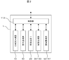
- FIG. 2 is a control block diagram showing control of the bill handling apparatus 1.
- the control unit 112 of the banknote handling apparatus 1 is connected to the main body control unit of the ATM via the control bus, and performs control in accordance with an instruction from the main body control unit. Further, the control unit 112 transmits the state of the banknote handling apparatus 1 to the main control unit, and controls the configuration mechanism unit including each unit according to the transaction process of the banknote handling apparatus 1.
- an actuator such as a drive motor or an electromagnetic solenoid
- the control unit 112 controls the conveyance of the bill by driving the actuator based on the command from the main body control unit or the detection signal of the sensor.
- the control unit 112 variably controls the speed of the drive motor of each bill transport path in multiple stages.
- the bill discrimination unit 40 can perform denomination discrimination and authenticity discrimination of a bill transported in any direction from the front to the back and from the rear to the front on the transport path 51. That is, the bill discrimination unit 40 can discriminate the denomination and the authenticity of the bill transported in both directions, and discriminates whether the bill is rejected or not.
- processing such as deposit transaction, withdrawal transaction, banknote replenishment, banknote recovery, forget-to-get recovery transaction, etc. is executed.
- the deposit transaction process is a process that mainly executes deposit counting process that performs authenticity determination, denomination determination, and counting of the bill inserted into the bill depositing and dispensing port 10.
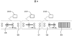
- the plurality of bills inserted into the bill receiving and dispensing port 10 are fed out to the bill conveying path 51 by the bill feeding mechanism of the bill conveying path 50.
- the first acceleration is performed.
- the bills fed out to the bill conveyance path 51 are delivered to the bill conveyance path 52.
- the second acceleration is performed.
- Vc is set such that Va ⁇ Vc ⁇ Vb holds.
- the current can be reduced even with the same motor to drive with a low torque, and power consumption can be reduced.
- it can be configured by a small motor with low output and low torque, and power consumption can be reduced and the apparatus can be miniaturized.
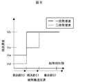
- the speed Va of the bill fed out at the bill deposit / withdrawal port 10 at the one-step acceleration, the bill discriminating portion 40 As shown in FIG. 6, with respect to the transport speed of the bill transport paths 50, 51, 52 by the drive motors 200 to 202, the speed Va of the bill fed out at the bill deposit / withdrawal port 10 at the one-step acceleration, the bill discriminating portion 40.
- the bill speed Vb (Va ⁇ Vb) when passing through the bill speed Vd fed out at the bill deposit / withdrawal port 10 at the two-step speed increase is Vd ⁇ Va, and Vb-Va> Va-Vd Is set so that Va ⁇ Vc ⁇ Vb is satisfied.
- the radius R of the F roller 80 can be made smaller compared to the one-step acceleration, and the apparatus can be miniaturized.
- the banknote having passed through the banknote discrimination unit 40 is transported by the banknote transport path 52. While the discrimination by the bill discrimination unit 40 is completed during conveyance of the bill conveyance path 52, the bill distribution gate 71 is switched by the control of the control unit 112 according to the discrimination result. As a result of the discrimination, when it is discriminated by the bill discriminating part 40 that the bill can be accepted, the control part 112 switches the bill distributing gate 71 to be connected to the bill conveying path 53 and makes the bill into the conveying paths 53, 54. It is transported and accumulated in the temporary storage unit 20.
- the control unit 112 switches the bill distribution gate 71 to connect to the bill conveyance path 55, and conveys the bill to the conveyance paths 55, 56. Then, it returns to the bill depositing / dispensing port 10 and returns it to the deposit transaction person.
- the bill discrimination unit 40 can discriminate the damage state of the bill, it is possible to change and control the conveyance speed of the bill based on the discrimination result. That is, when the bill is transported to the temporary storage unit 20 or the bill receiving / dispensing port 10 by the bill transport paths 53 to 56, the bill discriminating unit 40 determines that the bill is broken (for example, when the bill is cut) In this case, the control unit 112 prevents the further damage of the bill being conveyed by driving the conveyance motor so as to reduce the conveyance speed of the bill conveyance paths 53 to 56 to such an extent that pulling of the bill due to the speed difference is not strong. be able to. In addition, as a result of the discrimination of the bill state, when it is determined that the bill is in good condition, the control unit 112 controls to accelerate the conveyance speed of the bill conveyance paths 53 to 56 to improve the processing speed. Can.
- the control unit 112 switches the bill distribution gate 71 to connect the bill conveyance path 52 and the bill conveyance path 53, and connects the bill distribution gate 70 to the bill conveyance path 51 and the bill conveyance path 57.
- Switch to The bills delivered to the bill conveyance path 57 are switched to the bill distribution gates 72 to 74 in accordance with the denomination determined by the bill discrimination unit 40, and are stored in any of the bill storages 30 to 33.
- the plurality of bills accumulated in the temporary storage unit 20 are delivered to the bill transport path 53 by the bill delivery mechanism of the bill transport path 54, and then delivered to the bill transport path 52 and pass through the bill discrimination unit 40.
- acceleration is not performed in the transfer of the bill conveyance path 52 and the bill conveyance path 53 in the deposit counting process, but the conveyance speeds of the bill conveyance path 52 and the bill conveyance path 53 are increased to accelerate in the deposit storage process.
- the two-step acceleration is enabled in the bill conveyance path 54, the bill conveyance path 53, and the bill conveyance path 52.
- the bills having passed through the bill discriminating portion 40 are delivered from the bill transport path 52 to the bill transport path 51 and transported so as to be delivered to the bill transport path 57.
- the transfer speed of the bill transfer path 52 is controlled to be faster than the transfer speed of the bill transfer path 51 in the delivery of the bill between the bill transport path 51 and the bill transport path 52. Since it is not necessary to widen the bill interval L by speeding up, this speed increase is not performed. The speed may be increased to improve the storage processing speed.
- the present invention controls an independent drive motor also in other processings from which a bill delivery source, storage destination, conveyance path, and conveyance direction change. It can be realized in the same way.
- the bill conveyance path of the embodiment shown in FIG. 1 may be further divided and operated by an independent motor.
- the bill handling apparatus 1 when used in an area where the state of banknotes in circulation is bad, banknotes due to a rapid speedup can be generated by dividing the banknote transport path 51 and operating with independent motors in the deposit counting process. It is possible to reduce jamming caused by the load on the vehicle.
Landscapes
- Engineering & Computer Science (AREA)
- Mechanical Engineering (AREA)
- Physics & Mathematics (AREA)
- General Physics & Mathematics (AREA)
- Delivering By Means Of Belts And Rollers (AREA)
- Sheets, Magazines, And Separation Thereof (AREA)
- Separation, Sorting, Adjustment, Or Bending Of Sheets To Be Conveyed (AREA)
Abstract
L'invention concerne un dispositif de manipulation de billets qui comprend : une ouverture de dépôt/retrait de billets (10) où les billets à déposer/ retirer sont collectés; une unité de discrimination de billets (40) pour distinguer les billets; une partie de stockage temporaire (20) pour collecter et stocker temporairement les billets; des unités de stockage de billets (30 à 33) pour stocker et séparer de nouveau les billets; et des trajets d'acheminement de billets (50 à 61) pour acheminer les billets vers les unités de stockage de billets (30 à 33), les trajets d'acheminement de billets étant entrainés chacun par un moteur indépendant, et la vitesse d'acheminement de billets des trajets d'acheminement de billets étant soumise à une commande d'accélération par pas.
Applications Claiming Priority (2)
| Application Number | Priority Date | Filing Date | Title |
|---|---|---|---|
| JP2011019838A JP5622199B2 (ja) | 2011-02-01 | 2011-02-01 | 紙幣取扱装置 |
| JP2011-019838 | 2011-02-01 |
Publications (1)
| Publication Number | Publication Date |
|---|---|
| WO2012105125A1 true WO2012105125A1 (fr) | 2012-08-09 |
Family
ID=46562704
Family Applications (1)
| Application Number | Title | Priority Date | Filing Date |
|---|---|---|---|
| PCT/JP2011/078220 Ceased WO2012105125A1 (fr) | 2011-02-01 | 2011-12-06 | Dispositif de manipulation de billets |
Country Status (3)
| Country | Link |
|---|---|
| JP (1) | JP5622199B2 (fr) |
| CN (1) | CN102622806B (fr) |
| WO (1) | WO2012105125A1 (fr) |
Cited By (1)
| Publication number | Priority date | Publication date | Assignee | Title |
|---|---|---|---|---|
| WO2024088481A1 (fr) * | 2022-10-28 | 2024-05-02 | Giesecke+Devrient Currency Technology Gmbh | Procede et dispositif de transport d'elements d'electrode plats |
Families Citing this family (9)
| Publication number | Priority date | Publication date | Assignee | Title |
|---|---|---|---|---|
| JP5991902B2 (ja) * | 2012-11-15 | 2016-09-14 | 日立オムロンターミナルソリューションズ株式会社 | 紙葉類搬送装置、及び紙葉類搬送方法 |
| KR101660324B1 (ko) * | 2013-07-31 | 2016-09-29 | 히타치 오므론 터미널 솔루션즈 가부시키가이샤 | 지엽류 처리 장치 |
| CN104134279A (zh) * | 2014-07-28 | 2014-11-05 | 昆山古鳌电子机械有限公司 | 一种具有多次鉴别能力的纸币处理装置 |
| CN104732650B (zh) * | 2015-03-27 | 2017-06-16 | 深圳怡化电脑股份有限公司 | 一种纸币的处理方法及系统 |
| CN105761354A (zh) * | 2015-06-11 | 2016-07-13 | 深圳怡化电脑股份有限公司 | 一种自动存取款机走钞的控制方法 |
| CN109716404A (zh) * | 2016-09-28 | 2019-05-03 | 富士通先端科技株式会社 | 纸张处理设备以及纸张处理方法 |
| CN107424294A (zh) * | 2017-08-21 | 2017-12-01 | 昆山古鳌电子机械有限公司 | 纸币处理装置 |
| JP6956408B2 (ja) * | 2018-01-26 | 2021-11-02 | ローレル精機株式会社 | 紙葉類処理装置 |
| JP7690309B2 (ja) * | 2021-03-31 | 2025-06-10 | 株式会社オリジン | ローラー |
Citations (3)
| Publication number | Priority date | Publication date | Assignee | Title |
|---|---|---|---|---|
| JPH11339087A (ja) * | 1998-05-27 | 1999-12-10 | Mamiya Op Co Ltd | 紙幣収納装置 |
| JP2008152430A (ja) * | 2006-12-15 | 2008-07-03 | Hitachi Omron Terminal Solutions Corp | 紙葉類収納庫および紙葉類取扱装置 |
| JP2009251941A (ja) * | 2008-04-07 | 2009-10-29 | Hitachi Omron Terminal Solutions Corp | 紙葉類搬送装置、および紙幣処理機 |
Family Cites Families (3)
| Publication number | Priority date | Publication date | Assignee | Title |
|---|---|---|---|---|
| JP5042559B2 (ja) * | 2006-08-10 | 2012-10-03 | 日立オムロンターミナルソリューションズ株式会社 | 紙葉類取扱装置 |
| JP5089138B2 (ja) * | 2006-11-09 | 2012-12-05 | 日立オムロンターミナルソリューションズ株式会社 | 紙幣取扱装置 |
| JP5091628B2 (ja) * | 2007-11-07 | 2012-12-05 | 日立オムロンターミナルソリューションズ株式会社 | 紙葉類取扱装置 |
-
2011
- 2011-02-01 JP JP2011019838A patent/JP5622199B2/ja not_active Expired - Fee Related
- 2011-12-06 WO PCT/JP2011/078220 patent/WO2012105125A1/fr not_active Ceased
- 2011-12-19 CN CN201110427568.8A patent/CN102622806B/zh active Active
Patent Citations (3)
| Publication number | Priority date | Publication date | Assignee | Title |
|---|---|---|---|---|
| JPH11339087A (ja) * | 1998-05-27 | 1999-12-10 | Mamiya Op Co Ltd | 紙幣収納装置 |
| JP2008152430A (ja) * | 2006-12-15 | 2008-07-03 | Hitachi Omron Terminal Solutions Corp | 紙葉類収納庫および紙葉類取扱装置 |
| JP2009251941A (ja) * | 2008-04-07 | 2009-10-29 | Hitachi Omron Terminal Solutions Corp | 紙葉類搬送装置、および紙幣処理機 |
Cited By (2)
| Publication number | Priority date | Publication date | Assignee | Title |
|---|---|---|---|---|
| WO2024088481A1 (fr) * | 2022-10-28 | 2024-05-02 | Giesecke+Devrient Currency Technology Gmbh | Procede et dispositif de transport d'elements d'electrode plats |
| WO2024088480A1 (fr) * | 2022-10-28 | 2024-05-02 | Giesecke+Devrient Currency Technology Gmbh | Procédé et dispositif de transport de documents de valeur |
Also Published As
| Publication number | Publication date |
|---|---|
| CN102622806A (zh) | 2012-08-01 |
| JP5622199B2 (ja) | 2014-11-12 |
| JP2012160067A (ja) | 2012-08-23 |
| CN102622806B (zh) | 2015-09-23 |
Similar Documents
| Publication | Publication Date | Title |
|---|---|---|
| JP5622199B2 (ja) | 紙幣取扱装置 | |
| US9183691B2 (en) | Banknote pay-in/pay-out device and banknote processing machine | |
| JP4346474B2 (ja) | 紙幣処理装置 | |
| US20140190787A1 (en) | Bill storage box and bill handling device | |
| JP2012221123A (ja) | 紙葉類取扱装置 | |
| JP4804504B2 (ja) | 紙幣入出金装置、現金自動取引装置、および紙幣集積方法 | |
| JP3183288B2 (ja) | 紙幣入出金装置 | |
| JP3580468B2 (ja) | 紙幣取引装置 | |
| JP7172237B2 (ja) | 釣銭機 | |
| JP2002312833A (ja) | 貨幣入出金処理システム | |
| JP3766466B2 (ja) | 紙葉類の枚数確定方法及び紙葉類取扱装置 | |
| JP2014241168A (ja) | 紙幣取扱装置 | |
| JP2002312821A (ja) | 紙幣入出金処理システム | |
| KR20200037685A (ko) | 지폐 처리 장치 | |
| JPH0554222A (ja) | 紙幣両替装置 | |
| JP2009151703A (ja) | 紙幣処理装置 | |
| JP2003208654A (ja) | 紙幣入出金機 | |
| JPH1186092A (ja) | 紙葉類搬送装置および自動取引装置 | |
| JP5165196B2 (ja) | 紙幣入出金機 | |
| JP2532668B2 (ja) | 入出金装置 | |
| KR20090008756A (ko) | 금융자동화기기의 스택휠회전제어방법 | |
| JPH02259896A (ja) | 自動現金取引装置 | |
| JP3837233B2 (ja) | 貨幣取扱装置 | |
| JP2661764B2 (ja) | 入出金装置 | |
| JPH0225556B2 (fr) |
Legal Events
| Date | Code | Title | Description |
|---|---|---|---|
| 121 | Ep: the epo has been informed by wipo that ep was designated in this application |
Ref document number: 11857443 Country of ref document: EP Kind code of ref document: A1 |
|
| NENP | Non-entry into the national phase |
Ref country code: DE |
|
| 122 | Ep: pct application non-entry in european phase |
Ref document number: 11857443 Country of ref document: EP Kind code of ref document: A1 |