WO2012105167A1 - Terminal et procédé de transmission de qualité - Google Patents
Terminal et procédé de transmission de qualité Download PDFInfo
- Publication number
- WO2012105167A1 WO2012105167A1 PCT/JP2012/000236 JP2012000236W WO2012105167A1 WO 2012105167 A1 WO2012105167 A1 WO 2012105167A1 JP 2012000236 W JP2012000236 W JP 2012000236W WO 2012105167 A1 WO2012105167 A1 WO 2012105167A1
- Authority
- WO
- WIPO (PCT)
- Prior art keywords
- quality
- comp
- cell
- cells
- target group
- Prior art date
- Legal status (The legal status is an assumption and is not a legal conclusion. Google has not performed a legal analysis and makes no representation as to the accuracy of the status listed.)
- Ceased
Links
Images






Classifications
-
- H—ELECTRICITY
- H04—ELECTRIC COMMUNICATION TECHNIQUE
- H04W—WIRELESS COMMUNICATION NETWORKS
- H04W28/00—Network traffic management; Network resource management
- H04W28/16—Central resource management; Negotiation of resources or communication parameters, e.g. negotiating bandwidth or QoS [Quality of Service]
- H04W28/24—Negotiating SLA [Service Level Agreement]; Negotiating QoS [Quality of Service]
-
- H—ELECTRICITY
- H04—ELECTRIC COMMUNICATION TECHNIQUE
- H04W—WIRELESS COMMUNICATION NETWORKS
- H04W36/00—Hand-off or reselection arrangements
- H04W36/24—Reselection being triggered by specific parameters
- H04W36/30—Reselection being triggered by specific parameters by measured or perceived connection quality data
- H04W36/302—Reselection being triggered by specific parameters by measured or perceived connection quality data due to low signal strength
-
- H—ELECTRICITY
- H04—ELECTRIC COMMUNICATION TECHNIQUE
- H04W—WIRELESS COMMUNICATION NETWORKS
- H04W36/00—Hand-off or reselection arrangements
- H04W36/0005—Control or signalling for completing the hand-off
- H04W36/0009—Control or signalling for completing the hand-off for a plurality of users or terminals, e.g. group communication or moving wireless networks
Definitions
- the present invention relates to a terminal and a quality transmission method.
- the received power of a terminal communicating with a certain cell decreases due to the movement of the terminal itself or a change in the surrounding environment, and it becomes difficult to maintain the communication. In such a situation, the terminal can maintain communication by reconnecting to a cell with higher received power than the cell with which it is communicating.
- This cell switching process is called “handover”.
- the terminal needs to measure the received power of a signal transmitted from a cell existing in the vicinity of the “serving cell” and report it to the serving cell.
- a “serving cell” is a cell that notifies control information to a communicating terminal.
- the process performed by this terminal for measuring the reception power / reception quality of signals transmitted from neighboring cells is called “Measurement”.
- Non-Patent Document 1 describes the operation of measurement and handover in LTE.
- the base station performs settings related to Measurement for a terminal in communication.
- the settings related to the measurement include setting the measurement target (carrier frequency, etc.), setting the serving cell and neighbor cell list (cell ID list), setting the measurement timing, and setting details about the report value, etc. Point to.
- Detailed settings related to the report value are the settings of the report value type (Reference Signal Received Power (RSRP) and Reference Signal Received Quality (RSRQ), etc., defined in Non-Patent Document 2), report to the base station Indicates the setting of the trigger condition that prompts the transmission of the value and the setting of the reporting period.
- the terminal performs measurement using a reference signal (Reference Signal, RS) generated by a cell-specific sequence, a synchronization signal (Synchronization Signal), and a data signal transmitted from the serving cell and neighboring cells.
- RS Reference Signal
- the terminal measures the quality of signals transmitted from the serving cell and the neighboring cell based on the setting by the base station. And a terminal reports the measured value of quality to a base station (serving cell), when the predetermined
- the base station determines a handover destination cell based on the measured quality value reported from the terminal, and instructs the terminal to perform handover.
- the terminal disconnects communication with the handover source cell and connects to the handover destination cell to switch the serving cell.
- DCS Dynamic Cell Selection
- JT Joint Transmission
- FIG. 1 shows two cell groups (in the figure, a CoMP group), and each cell group is composed of three RRHs and one BSP. Each cell corresponds to each pair group of each RRH and one BSP.
- BSP Baseband Signal Processor
- RRH Remote Radio Head
- the BSP is a processor that performs baseband signal processing such as generation of a transmission signal to a terminal, demodulation of a reception signal from the terminal, and scheduling of a plurality of terminals.
- the BSP is connected to a plurality of RRHs by wire (optical fiber) and communicates with a terminal via the RRH.
- the BSP may also be called a Base Band Unit (BBU).
- BBU Base Band Unit
- the RRH is composed of an amplifier and an antenna.
- the baseband signal generated by the BSP is input in the downlink, and the signal obtained by performing transmission processing such as D / A conversion, up-conversion, and amplification on the input baseband signal, Send to terminal via antenna.
- the RRH sends a baseband signal obtained by performing reception processing such as down-conversion and A / D conversion on the received signal from the terminal received via the antenna to the BSP.
- the RRH is also called “overhang base station” and is recognized as a cell by the terminal.
- CoMP is applied only between a plurality of RRHs (cells) connected to one BSP. That is, CoMP is not applied between a plurality of RRHs with different connected BSPs. This is because the performance effect by CoMP is expected to be small. This is because if this type of CoMP is to be executed, it is necessary to define a new I / F between the BSPs, and the control delay increases.
- a configuration including one BSP and a plurality of RRHs connected to the BSP is referred to as a “CoMP group”. Note that the CoMP group may be referred to as a CoMP cooperating set.
- An object of the present invention is to provide a terminal and a quality transmission method capable of realizing appropriate handover control even when a cell group in which a plurality of cells cooperate in downlink communication is included in the communication system. is there.
- a terminal receives a reference signal transmitted from a quality calculation target group configured by all or part of a plurality of cells constituting a cell group that cooperatively transmits downlink data. And a calculation means for calculating a total quality value for the quality calculation target group based on the received reference signal, and the quality calculation target when the calculated total quality value exceeds a first threshold value. Transmitting means for transmitting information on the quality of the reference signal transmitted from at least one cell among a plurality of cells included in the group to a cell in communication.
- the quality transmission method receives a reference signal transmitted from a quality calculation target group configured by all or part of a plurality of cells constituting a cell group that cooperatively transmits downlink data. Based on the received reference signal, a total quality value for the quality calculation target group is calculated, and when the calculated total quality value exceeds a first threshold value, the total quality value is included in the quality calculation target group Information on the quality of the reference signal transmitted from at least one cell among the plurality of cells is transmitted to the cell in communication.
- the present invention it is possible to provide a terminal and a quality transmission method capable of realizing appropriate handover control even when a cell group in which a plurality of cells cooperate in downlink communication is included in the communication system. it can.
- Diagram for explaining CoMP group The figure which shows the communication system containing a CoMP group The figure which shows an example of the reception level of each cell in the communication system of FIG. Diagram used to explain quality reporting issues by terminals Main configuration diagram of terminal according to Embodiment 1 of the present invention
- the block diagram which shows the structure of the terminal which concerns on Embodiment 1 of this invention.
- the block diagram which shows the structure of the base station which concerns on Embodiment 1 of this invention.
- Diagram for explaining operation of terminal and base station Diagram for explaining threshold setting for CoMP by terminal, quality calculation, trigger condition judgment, and quality report The figure which uses for the quality calculation by the terminal which concerns on Embodiment 2 of this invention, trigger condition determination, and description of a quality report
- the present inventors have found the following problem that arises when the conventional handover control method is directly applied to a communication system including a cell group (that is, a CoMP group) in which a plurality of cells cooperate in downlink communication. It was.
- FIG. 2 shows a communication system including a CoMP group.
- cells #D, E, and F among cells #A to F are connected to one BSP to form one CoMP group.
- cells #A, B, and C are cells to which CoMP is not applied.
- FIG. 3 is a diagram showing an example of the reception levels (report values) of the cells #A to #F.
- the quality of the cell #A having the highest quality among the cells having the quality exceeding the threshold is reported to the base station. For this reason, the terminal that made the report hands over to cell #A.
- the terminal that made the report hands over to cell #A.
- the quality information of cells #D, E, and F is reported to the base station in the conventional measurement method, even though the quality of cells #D, E, and F to which CoMP is applicable is the highest. Not. This is because in the conventional Measurement method, the quality of a cell unit is compared with a threshold value, and only the quality of the cell having the highest quality among the cells having the quality exceeding the threshold value is reported. That is, in the example shown in FIG. 3, since the cells #D, E, and F to which CoMP can be applied do not exceed the threshold and do not correspond to the highest quality cell, Don't be.
- the terminal can report all the qualities of the cells #A to F to the base station, and as a result, the base station can estimate the performance improvement effect by CoMP.
- this method has a problem that system overhead increases because reports frequently occur and the number of cells to be reported increases.
- FIG. 5 is a main configuration diagram of the terminal according to Embodiment 1 of the present invention.
- reception processing section 102 receives a reference signal transmitted from a quality calculation target group configured by all of the cell groups constituting the cell group that cooperatively transmits downlink data, and receives the received reference signal.
- the reference signal is output to the CoMP quality calculation unit 105.
- the CoMP quality calculation unit 105 calculates a total quality value for the quality calculation target group based on the received reference signal, and outputs the calculated total quality value to the measurement control unit 106.
- the Measurement control unit 106 transmits, to the serving cell, information related to the quality of the reference signal transmitted from at least one cell in the cell group included in the quality calculation target group when the calculated total quality value exceeds the threshold value. To do.
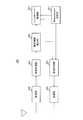
- FIG. 6 is a block diagram showing a configuration of the terminal according to Embodiment 1 of the present invention.
- a terminal 100 includes a reception unit 101, a reception processing unit 102, a measurement setting unit 103, a non-CoMP quality calculation unit 104, a CoMP quality calculation unit 105, a measurement control unit 106, and a transmission processing unit. 107 and a transmission unit 108.
- the receiving unit 101 receives a signal transmitted from the base station 200 described later via an antenna, and performs reception radio processing (down-conversion, A / D conversion, etc.) on the received signal.
- the reception signal after reception radio processing obtained in this way is output to the reception processing unit 102.
- the reception processing unit 102 performs reception processing (demodulation, decoding, etc.) on the signal received from the reception unit 101, and uses a signal used for measurement from the signal after reception processing (that is, a reference signal and a data signal transmitted by each cell) Etc.). This extracted signal is output to Measurement setting section 103, Non-CoMP quality calculating section 104, and CoMP quality calculating section 105.
- the measurement setting unit 103 extracts control information transmitted from the base station 200 corresponding to the serving cell from the signal received from the reception processing unit 102, and extracts the control information from the non-CoMP quality calculation unit 104, the CoMP quality calculation unit 105, And output to the Measurement control unit 106.
- the control information transmitted from the base station 200 corresponding to the serving cell includes, in addition to information conventionally used in Measurement, a cell group that is a target of CoMP quality estimation (that is, CoMP quality calculation) among cell groups included in the CoMP group.
- Target group identification information and a threshold value for CoMP.
- the information used in the measurement includes the measurement target (carrier frequency, etc.), the serving cell and neighbor cell list (cell ID list), the measurement timing, and details about the report value (type of report value, trigger for transmitting the report value). Conditions, IDs associated with trigger conditions, and the like).
- the CoMP quality calculation target group matches the CoMP group.
- the CoMP quality calculation target group identification information (or CoMP group identification information) includes a plurality of cell IDs corresponding to a plurality of cells belonging to the group. Further, the CoMP quality calculation target group identification information (or CoMP group identification information) may be notified from the base station 200 corresponding to the serving cell to the terminal 100 by RRC signaling. Furthermore, the CoMP quality calculation target group identification information may be included in the cell ID and notified from the base station 200 corresponding to the serving cell to the terminal 100, or included in the broadcast information and corresponding to the serving cell. Notification may be made from the base station 200 to the terminal 100.
- the CoMP threshold value is independently set to a value different from the conventional threshold value for measurement quality of each cell (that is, the Non-CoMP threshold value).
- the non-CoMP quality calculation unit 104 measures the quality of the serving cell and neighboring cells (for example, RSRP or RSRQ) on a cell basis based on the control information received from the measurement setting unit 103. For this quality measurement, a reference signal or a data signal transmitted from each of the serving cell and the neighboring cell is used. And the quality measurement value about each of a serving cell and an adjacent cell is output to Measurement control part 106. FIG. This quality measurement may be referred to as “Non-CoMP quality”.
- the CoMP quality calculation unit 105 calculates the quality (for example, RSRP or RSRQ) in consideration of the quality improvement effect by CoMP based on the control information received from the measurement setting unit 103 for each CoMP quality calculation target group. That is, the CoMP quality calculation unit 105 measures each quality (for example, RSRP or RSRQ) of a plurality of cells constituting the group indicated by the CoMP quality calculation target group identification information included in the control information received from the measurement setting unit 103. To do. Then, the CoMP quality calculation unit 105 calculates “total quality (that is, CoMP quality)” for the CoMP quality calculation target group based on the plurality of quality results measured for the plurality of cells.
- the quality for example, RSRP or RSRQ
- the CoMP quality calculation unit 105 combines reference signals received from each of a plurality of cells constituting a group indicated by the CoMP quality calculation target group identification information, and calculates “total quality” based on the combined signal. calculate. Specifically, the CoMP quality calculation unit 105 receives a reference signal received from each of a plurality of cells constituting a group indicated by the CoMP quality calculation target group identification information and a replica signal (previously transmitted from each cell). The frequency response in each cell is calculated by performing a correlation operation on the same signal as the reference signal. Based on this frequency response, the CoMP quality calculation unit 105 can calculate the optimal transmission weight of each cell. Therefore, the CoMP quality calculation unit 105 can calculate “total quality” based on the combined signal to which the calculated optimal transmission weight is applied.
- the calculated total quality value is output to the measurement control unit 106.
- the Measurement control unit 106 sets a CoMP threshold based on the control information received from the Measurement setting unit 103, and is included in the CoMP quality calculation target group when the total quality value received from the CoMP quality calculation unit 105 exceeds the CoMP threshold.
- Non-CoMP quality of at least one cell of the plurality of cells to be transmitted is transmitted.
- the measurement control unit 106 selects at least one cell among a plurality of cells included in the CoMP quality calculation target group when the total quality value received from the CoMP quality calculation unit 105 exceeds the CoMP threshold. .
- the measurement control unit 106 specifies the cell ID and Non-CoMP quality of the selected cell, and information that clearly indicates that the total quality value exceeds the threshold value (for example, notified from the base station 200 in advance). Report information including IDs associated with a plurality of trigger conditions is generated. This report information is transmitted via the transmission processing unit 107, the transmission unit 108, and the antenna.
- the transmission processing unit 107 performs transmission processing (reference signal multiplexing, encoding processing, modulation processing, etc.) on the report information generated by the measurement control unit 106 and outputs the signal after the transmission processing to the transmission unit 108. .
- the transmission unit 108 performs transmission radio processing (frequency conversion to radio frequency, power amplification, transmission filter processing, etc.) on the transmission signal received from the transmission processing unit 107, and transmits the signal after transmission radio processing via an antenna. Send.
- transmission radio processing frequency conversion to radio frequency, power amplification, transmission filter processing, etc.
- FIG. 7 is a block diagram showing the configuration of the base station according to Embodiment 1 of the present invention.
- the base station 200 includes a measurement setting unit 201, a transmission processing unit 202, a transmission unit 203, a reception unit 204, a reception processing unit 205, a report information extraction unit 206, a handover control unit 207,
- Have Base station 200 corresponds to a serving cell, and is a base station that belongs to a CoMP group or a base station that does not belong to a CoMP group (that is, a base station that independently transmits downlink data).
- the transmission unit 203 and the reception unit 204 belong to the RRH, and the transmission processing unit 202, the reception processing unit 205, the report information extraction unit 206, The handover control unit 207 belongs to the BSP.
- the measurement setting unit 201 generates control information necessary for measurement in the terminal 100.
- this control information includes, in addition to information conventionally used in Measurement, identification information of a cell group (that is, a CoMP quality calculation target group) targeted for CoMP quality estimation among cell groups included in the CoMP group. And a threshold for CoMP.
- the information used in the measurement includes the measurement target (carrier frequency, etc.), the serving cell and neighbor cell list (cell ID list), the measurement timing, and details about the report value (type of report value, trigger for transmitting the report value). Conditions, IDs associated with trigger conditions, and the like).
- the Measurement setting unit 201 outputs the generated control information to the handover control unit 207 and transmits it to the terminal 100 via the transmission processing unit 202, the transmission unit 203, and the antenna.
- the transmission processing unit 202 performs transmission processing (multiplexing of reference signals, encoding processing, modulation processing, etc.) on the control information generated by the measurement setting unit 201 and the handover instruction information generated by the handover control unit 207.
- the signal after transmission processing is output to the transmission 203.
- the transmission unit 203 performs transmission radio processing (frequency conversion to radio frequency, power amplification, transmission filter processing, etc.) on the transmission signal received from the transmission processing unit 202, and transmits the signal after transmission radio processing via an antenna. Send.
- transmission radio processing frequency conversion to radio frequency, power amplification, transmission filter processing, etc.
- the receiving unit 204 receives a signal transmitted from the terminal 100 via an antenna, and performs reception radio processing (down-conversion, A / D conversion, etc.) on the received signal.
- the reception signal after reception wireless processing obtained in this way is output to reception processing section 205.
- the reception processing unit 205 performs reception processing (demodulation, decoding, etc.) on the signal received from the reception unit 204, and the received signal is output to the report information extraction unit 206.
- the report information extraction unit 206 extracts the report information transmitted from the terminal 100 from the signal received from the reception processing unit 205, and outputs the extracted report information to the handover control unit 207.
- this report information as described above, the cell ID and Non-CoMP quality of the selected cell and information clearly indicating that the report is a report that the total quality value exceeds the threshold (for example, from the base station 200 in advance). ID associated with a plurality of notified trigger conditions).
- the handover control unit 207 performs handover control of the terminal 100 based on the report information received from the report information extraction unit 206. Specifically, the handover control unit 207 determines whether to hand over the terminal 100 based on the report information received from the report information extraction unit 206 and the control information received from the measurement setting unit 201, and when performing the handover. A cell to be handed over (that is, a handover destination cell) is determined. In the determination, report information from the terminal 100 (type of trigger condition, quality value included in the report information (including CoMP quality and Non-CoMP quality), cell identification information corresponding to the quality value), and each Cell traffic conditions and the like are considered. Here, in the above determination, it is necessary to consider not only the CoMP quality but also the Non-CoMP quality. This is because CoMP is not applied to the control signal and is transmitted from only one cell (serving cell).
- the handover control unit 207 determines to perform handover of the terminal 100, the handover control unit 207 transmits handover instruction information to the terminal 100 via the transmission processing unit 202, the transmission unit 203, and the antenna. .
- FIG. 8 is a diagram for explaining operations of the terminal 100 and the base station 200.
- step ST301 the measurement setting unit 201 of the base station 200 transmits control information (that is, measurement parameters) necessary for measurement in the terminal 100 to the terminal 100.
- control information that is, measurement parameters
- step ST302 the CoMP quality calculation unit 105 of the terminal 100, based on the control information transmitted from the base station 200, the quality (for example, each of a plurality of cells constituting the group indicated by the CoMP quality calculation target group identification information) , RSRP or RSRQ). Then, the CoMP quality calculation unit 105 calculates “total quality (that is, CoMP quality)” of the CoMP quality calculation target group based on the measured quality results of the plurality of cells. At this time, the Non-CoMP quality calculation unit 104 measures the quality of the serving cell and the neighboring cell on a cell basis based on the control information transmitted from the base station 200.
- step ST303 the measurement control unit 106 of the terminal 100 determines whether or not the total quality value received from the CoMP quality calculation unit 105 exceeds the CoMP threshold (that is, whether the trigger condition is satisfied).
- the measurement control unit 106 in step ST304, at least one cell among the plurality of cells included in the CoMP quality calculation target group.
- Non-CoMP quality is transmitted. This Non-CoMP quality is included in the report information and transmitted.
- the handover control unit 207 of the base station 200 executes the handover control of the terminal 100 based on the report information transmitted from the terminal 100. Specifically, the handover control unit 207 determines whether to hand over the terminal 100 based on the report information received from the report information extraction unit 206 and the control information received from the measurement setting unit 201, and when performing the handover. A cell to be handed over (that is, a handover destination cell) is determined.
- the handover control unit 207 transmits handover instruction information to the terminal 100 in step ST306.
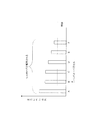
- FIG. 9 is a diagram for explaining CoMP threshold setting, quality calculation, trigger condition determination, and quality report by the terminal 100.
- cells #A to C are cells to which CoMP is not applied
- cells #D to F are cells belonging to the same CoMP quality calculation target group.
- the measurement setting unit 103 extracts control information transmitted from the base station 200 corresponding to the serving cell from the signal received from the reception processing unit 102, and extracts the control information from the non-CoMP quality calculation unit 104, the CoMP quality calculation unit 105, And output to the Measurement control unit 106.
- the control information transmitted from the base station 200 corresponding to this serving cell includes, in addition to information conventionally used in measurement, a cell group (that is, CoMP quality estimation target) among the cell groups included in the CoMP group. Identification group) and a threshold for CoMP.
- the information used in the measurement includes the measurement target (carrier frequency, etc.), the serving cell and neighbor cell list (cell ID list), the measurement timing, and details about the report value (type of report value, trigger for transmitting the report value). Conditions, IDs associated with trigger conditions, and the like).
- the CoMP threshold value is independently set to a value different from the conventional threshold value for measurement quality of each cell (that is, the Non-CoMP threshold value).
- the threshold for Non-CoMP is a threshold that is compared with the reception quality for one cell.
- the CoMP threshold value is larger than the Non-CoMP threshold value (see FIG. 9).
- the non-CoMP quality calculation unit 104 Based on the control information received from the measurement setting unit 103, the non-CoMP quality calculation unit 104 measures the quality (for example, RSRP or RSRQ) of the serving cell and the neighboring cell in units of cells.
- the quality for example, RSRP or RSRQ
- the CoMP quality calculation unit 105 measures each quality (for example, RSRP or RSRQ) of a plurality of cells constituting the group indicated by the CoMP quality calculation target group identification information included in the control information received from the measurement setting unit 103. To do. Then, the CoMP quality calculation unit 105 calculates “total quality (that is, CoMP quality)” for the CoMP quality calculation target group based on the plurality of quality results measured for the plurality of cells. Here, the CoMP quality calculation target group matches the CoMP group.
- the CoMP quality calculation unit 105 combines reference signals received from each of a plurality of cells constituting a group indicated by the CoMP quality calculation target group identification information, and calculates “total quality” based on the combined signal. calculate. Specifically, the CoMP quality calculation unit 105 receives a reference signal received from each of a plurality of cells constituting a group indicated by the CoMP quality calculation target group identification information and a replica signal (previously transmitted from each cell). The frequency response in each cell is calculated by performing a correlation operation on the same signal as the reference signal. Based on this frequency response, the CoMP quality calculation unit 105 can calculate the optimal transmission weight of each cell. Therefore, the CoMP quality calculation unit 105 can calculate “total quality” based on the combined signal to which the calculated optimal transmission weight is applied. In FIG. 9, the “total quality” for the cells #D to F is calculated.
- the measurement control unit 106 sets a CoMP threshold based on the control information received from the measurement setting unit 103 as described above, and determines whether or not the total quality value received from the CoMP quality calculation unit 105 exceeds the CoMP threshold. . That is, the fact that the total quality value received from the CoMP quality calculation unit 105 exceeds the CoMP threshold is a trigger condition for transmitting the Non-CoMP quality of a plurality of cells included in the CoMP quality calculation target group. In FIG. 9, since the CoMP quality for the cells #D to F exceeds the CoMP threshold, the trigger condition is satisfied. Further, since the quality of the cell #A also exceeds the non-CoMP threshold, the trigger condition for transmitting the non-CoMP quality of the cell to which the non-CoMP is not applied is satisfied.
- the value of the CoMP quality is larger than the value of the Non-CoMP quality. Therefore, by setting the CoMP threshold separately in addition to the Non-CoMP threshold, the non-CoMP quality of the CoMP quality calculation target group is set only when a large transmission characteristic improvement effect can be expected by using CoMP. Can be sent.
- the measurement control unit 106 includes at least one of the plurality of cells included in the CoMP quality calculation target group. Transmit the Non-CoMP quality of one cell.
- the quality of the cell #A exceeds the non-CoMP threshold
- the quality is reported from the terminal 100 to the base station 200.
- the CoMP quality for the cells #D to F exceeds the CoMP threshold
- the Non-CoMP quality of at least one cell among the cells #D to F is also reported from the terminal 100 to the base station 200. .
- all cells included in the CoMP quality calculation target group may be non-CoMP quality transmission target cells.
- the base station 200 can select a handover destination cell from a plurality of cells included in the CoMP quality calculation target group in consideration of traffic conditions.
- the cells that are transmission targets of Non-CoMP quality may be some cells included in the CoMP quality calculation target group.
- the cell that is the transmission target of Non-CoMP quality may be only the cell that has the maximum Non-CoMP quality. Thereby, the base station 200 can hand over the terminal 100 to a cell having the best quality in the CoMP group.
- the Measurement control unit 106 may transmit the CoMP quality in addition to the Non-CoMP quality of the CoMP quality calculation target group. Thereby, the base station 200 can grasp not only that the CoMP quality exceeds the threshold value but also the absolute value of the quality.
- CoMP quality calculation section 105 calculates the overall quality value of the quality calculation target group based on the reference signal transmitted from the quality calculation target group, and measures the measurement.
- the control unit 106 changes the quality of the reference signal transmitted from at least one cell in the cell group included in the quality calculation target group to the serving cell ( That is, it transmits to the base station 200).
- the terminal 100 can be handed over to a cell where performance improvement by CoMP can be expected while preventing frequent occurrence of quality reports, and as a result, system performance can be improved. That is, even when the communication system includes a cell group that performs downlink communication in cooperation with a plurality of cells, appropriate handover control can be realized.
- the CoMP quality calculation unit 105 calculates a total quality value based on a combined signal obtained by combining the received reference signal group corresponding to the quality calculation target group using the calculated optimal transmission weight.
- the base station 200 cannot calculate the total quality value of the quality calculation target group.
- the terminal 100 does not report a frequency response (complex number) with a large amount of information, and information equivalent to a power level with a small amount of information or SINR (RSRP, RSRQ, etc.) Report. Therefore, since the base station 200 cannot calculate the optimum transmission weight (complex number) of each cell obtained from the frequency response, the base station 200 cannot accurately calculate the total quality value of the quality calculation target group.
- SINR SINR
- the trigger condition for transmitting the Non-CoMP quality of the CoMP quality calculation target group is that the total quality value for the CoMP quality calculation target group exceeds the CoMP threshold.
- the second embodiment even one non-addition value group obtained by adding an offset value to each Non-CoMP quality of a plurality of cells included in the CoMP quality calculation target group.
- Exceeding the CoMP threshold is a trigger condition for transmitting the Non-CoMP quality of the CoMP quality calculation target group.
- Measurement setting section 103 extracts control information transmitted from base station 200 corresponding to the serving cell from the signal received from reception processing section 102, and calculates the control information for Non-CoMP quality calculation.
- Unit 104, CoMP quality calculation unit 105, and measurement control unit 106 extracts control information transmitted from base station 200 corresponding to the serving cell from the signal received from reception processing section 102, and calculates the control information for Non-CoMP quality calculation.
- Unit 104, CoMP quality calculation unit 105, and measurement control unit 106 is included in terminal 100 of Embodiment 2
- the same value as the threshold for measurement quality of each conventional cell (that is, the threshold for Non-CoMP) is set for the threshold for CoMP. That is, in Embodiment 2, only the threshold for Non-CoMP may be set.
- the CoMP quality calculation unit 105 calculates a quality (for example, RSRP or RSRQ) in consideration of the quality improvement effect by CoMP for each cell constituting the CoMP quality calculation target group. .
- the CoMP quality calculation unit 105 measures the quality (for example, RSRP or RSRQ) of each of a plurality of cells constituting the group indicated by the CoMP quality calculation target group identification information included in the control information received from the measurement setting unit 103. Then, the CoMP quality calculation unit 105 calculates “total quality (that is, CoMP quality)” for the CoMP quality calculation target group based on the plurality of quality results measured for the plurality of cells.
- the CoMP quality calculation unit 105 determines the quality (for example, RSRP or RSRQ) of each of the cells constituting the group indicated by the CoMP quality calculation target group identification information included in the control information received from the measurement setting unit 103. ). Then, the CoMP quality calculation unit 105 calculates “total quality” by adding an offset value to each of the plurality of quality results measured for the plurality of cells. Here, the offset value is set for each CoMP quality calculation target group.
- the Measurement control unit 106 transmits the Non-CoMP quality of at least one cell among the plurality of cells included in the CoMP quality calculation target group. To do. Specifically, the measurement control unit 106 adds at least one of the added value groups obtained by adding the offset value to the Non-CoMP quality of each of the plurality of cells included in the CoMP quality calculation target group. When the threshold for CoMP is exceeded, the Non-CoMP quality of at least one cell among a plurality of cells included in the CoMP quality calculation target group is transmitted.
- the measurement setting unit 201 determines the above-described offset value. This offset value is included in the control information and transmitted to the terminal 100 via the transmission processing unit 202, the transmission unit 203, and the antenna.
- FIG. 10 is a diagram for explaining quality calculation, trigger condition determination, and quality report by the terminal 100.
- cells #A to C are cells to which CoMP is not applied
- cells #D to F are cells belonging to the same CoMP quality calculation target group.
- the non-CoMP quality calculation unit 104 Based on the control information received from the measurement setting unit 103, the non-CoMP quality calculation unit 104 measures the quality (for example, RSRP or RSRQ) of the serving cell and the neighboring cell in units of cells.
- the quality for example, RSRP or RSRQ
- the CoMP quality calculation unit 105 calculates a quality (for example, RSRP or RSRQ) in consideration of the quality improvement effect by CoMP for each cell constituting the CoMP quality calculation target group. .
- the CoMP quality calculation unit 105 measures the quality (for example, RSRP or RSRQ) of each of a plurality of cells constituting the group indicated by the CoMP quality calculation target group identification information included in the control information received from the measurement setting unit 103. Then, the CoMP quality calculation unit 105 calculates “total quality (that is, CoMP quality)” for the CoMP quality calculation target group based on the plurality of quality results measured for the plurality of cells.
- the CoMP quality calculation unit 105 determines the quality (for example, RSRP or RSRQ) of each of the cells constituting the group indicated by the CoMP quality calculation target group identification information included in the control information received from the measurement setting unit 103. ) And adding an offset value to each of the plurality of quality results measured for the plurality of cells, thereby calculating “total quality”.
- the quality for example, RSRP or RSRQ
- the offset value is set to a value that satisfies Equation (1) so that the quality of the cell that satisfies the minimum quality necessary for receiving the control signal of each cell is reported.
- the measurement control unit 106 determines whether or not the total quality value received from the CoMP quality calculation unit 105 exceeds the non-CoMP threshold. That is, the fact that the total quality value received from the CoMP quality calculation unit 105 exceeds the Non-CoMP threshold value is a trigger condition for transmitting the Non-CoMP quality of a plurality of cells included in the CoMP quality calculation target group. Specifically, even one of the added value groups obtained by adding an offset value to the Non-CoMP quality of each of a plurality of cells included in the CoMP quality calculation target group may exceed the Non-CoMP threshold.
- the trigger condition for transmitting the Non-CoMP quality of a plurality of cells included in the CoMP quality calculation target group is illustrated in FIG.
- the trigger condition is satisfied. Further, since the quality of the cell #A also exceeds the non-CoMP threshold, the trigger condition for transmitting the non-CoMP quality of the cell to which the non-CoMP is not applied is satisfied.
- the Measurement control unit 106 transmits the Non-CoMP quality of at least one cell among the plurality of cells included in the CoMP quality calculation target group when the trigger condition is satisfied.
- the case where the trigger condition is satisfied means that at least one of the added value groups obtained by adding the offset value to the Non-CoMP quality of each of the plurality of cells included in the CoMP quality calculation target group is Non-CoMP. This is the case where the threshold for use is exceeded.
- the quality of the cell #A exceeds the non-CoMP threshold, so the quality is reported from the terminal 100 to the base station 200.
- the CoMP quality for the cells #D to F exceeds the non-CoMP threshold, the non-CoMP quality of at least one of the cells #D to F is also reported from the terminal 100 to the base station 200. Is done.
- all cells included in the CoMP quality calculation target group may be non-CoMP quality transmission target cells.
- the base station 200 can select a handover destination cell from a plurality of cells included in the CoMP quality calculation target group in consideration of traffic conditions.
- the cells that are transmission targets of Non-CoMP quality may be some cells included in the CoMP quality calculation target group.
- the cell that is the transmission target of Non-CoMP quality may be only the cell that has the maximum Non-CoMP quality. Thereby, the base station 200 can hand over the terminal 100 to a cell having the best quality in the CoMP group.
- the Measurement control unit 106 may transmit the CoMP quality in addition to the Non-CoMP quality of the CoMP quality calculation target group. Thereby, the base station 200 can grasp not only that the CoMP quality exceeds the threshold value but also the absolute value of the quality.
- CoMP quality calculation section 105 sets a predetermined offset value as the total quality value for each quality value of the received reference signal group corresponding to the quality calculation target group.
- An addition value group is calculated by addition, and when the measurement control unit 106 exceeds the threshold for Non-CoMP in at least one of the addition value groups, at least one of the cell groups included in the quality calculation target group.
- the quality of the reference signal transmitted from one cell is transmitted to the serving cell (that is, base station 200) in communication.
- the trigger condition may be that the total quality value exceeds the CoMP threshold value and one of the added value groups exceeds the Non-CoMP threshold value.
- the terminal 100 can report more accurate CoMP quality to the base station 200 while ensuring the quality of the control signal at the handover destination.
- the total quality value is calculated based on a synthesized signal obtained by synthesizing the reference signal received from the CoMP quality calculation target group.
- the addition value group is obtained by adding an offset value to each Non-CoMP quality of a plurality of cells included in the CoMP quality calculation target group.
- the trigger condition may be that even one of the added value groups obtained by adding the offset value to the CoMP quality exceeds the “CoMP threshold”.
- the same effect can be obtained by setting the offset value to a value that satisfies Equation (2) so that the quality of the cell that satisfies the quality necessary for receiving the control signal of each cell is reported. Offset ⁇ CoMP threshold-quality required for receiving control signal (2)
- Non-CoMP quality calculation unit 104 and the CoMP quality calculation unit 105 have been described as separate functional units, but the present invention is not limited to this, and a single function May be part.
- the CoMP quality calculation target group is a CoMP.
- You may be comprised by the one part cell group of the some cell which comprises a group. That is, the set of CoMP groups may partially include the set of CoMP quality calculation target groups.
- the CoMP quality estimation target group is a subset of the CoMP group (for example, CoMP measurement set or RRM (Radio Resource Management) measurement set) defined in Non-Patent Document 3 (TR36.814 V2.0.0). Also good.
- the CoMP quality calculation target group may be notified to the terminal as a cell group, or may be notified to the terminal as CSI (Channel State Information) -RS (Reference Signal) as a quality measurement target. In the latter case, the CoMP quality calculation target group may be a CSI-RS measurement candidate list.
- the CoMP quality calculation target group configures only the cell group in which the difference between the maximum quality value related to the plurality of cells included in the CoMP group and the quality of each cell included in the CoMP group is within a predetermined value. It is good as an element.
- the CoMP quality calculation target group may include only the cell group in which the difference between the quality of the serving cell included in the CoMP group and the quality of each cell included in the CoMP group is within a predetermined value.
- the CoMP quality calculation target group is the top N of the quality among a plurality of cells included in the CoMP group (N is a natural number of 2 or more, and is a parameter that the base station 200 sets in advance for the terminal 100). Only these cells may be used as components.
- the base station 200 may use the CoMP quality calculation target group as a CoMP application target unit.
- CoMP the resource consumption per terminal increases as the number of cells for cooperative transmission increases. For this reason, if the number of cooperative cells is too large, the performance of a terminal to which CoMP is applied is improved, but the resources that can be used by other terminals are reduced, and there is a problem that the average cell throughput is reduced.
- the CoMP application target unit may be referred to as CoMP transmission point (s).
- the CoMP threshold value is different from the Non-CoMP threshold value.
- the present invention is not limited to this, and the Non-CoMP threshold value may be used as the CoMP threshold value. good. This also makes it possible to implement appropriate handover control even when the communication system includes a cell group that performs downlink communication in cooperation with a plurality of cells.
- the Non-CoMP quality calculation target group Non -CoMP quality can be transmitted.
- Embodiment 2 only the Non-CoMP threshold is used. However, the present invention is not limited to this, and the CoMP threshold is set as the Non-CoMP threshold as in Embodiment 1. It may be a different value.
- different values may be set as the CoMP threshold value according to the number of cells constituting the CoMP quality calculation target group. That is, the CoMP threshold is set to a larger value as the number of cells constituting the CoMP quality calculation target group is larger.
- Base station 200 may set in advance a threshold for CoMP corresponding to the number of cells constituting the CoMP quality calculation target group for terminal 100, or for CoMP according to the number of cells constituting the CoMP quality calculation target group.
- a threshold calculation formula may be set in advance.
- the terminal 100 with a small number of constituent cells of the CoMP quality calculation target group set from the base station 200 reports the quality preferentially, and is handed over to a cell where the performance improvement effect by CoMP can be obtained. Therefore, the resource utilization efficiency can be improved.
- the threshold for CoMP may be switched based on the applied CoMP method. Specifically, the threshold for CoMP may be switched depending on whether the applied CoMP method is DCS or JT.
- the CoMP threshold value when the applied CoMP scheme is JT is larger than the CoMP threshold value when the applied CoMP scheme is DCS. That is, since the number of cells transmitting data is different between DCS and JT, the CoMP quality has a different value (that is, the quality at JT is higher than the quality at DCS). Therefore, if the CoMP threshold when the applied CoMP scheme is JT and the CoMP threshold when the applied CoMP scheme is DCS are matched with a value suitable for the quality at DCS, There are problems that frequently occur.
- the threshold for CoMP is switched depending on whether the applied CoMP method is DCS or JT. Since DCS is a system in which the number of base stations 200 transmitting data at any time is always one, the CoMP threshold when the applied CoMP system is DCS is the Non-CoMP threshold. The same value may be set.
- a transmission point may be distinguished by CSI-RS. That is, the measurement target cell can be read as the measurement target CSI-RS.
- each functional block used in the description of each of the above embodiments is typically realized as an LSI which is an integrated circuit. These may be individually made into one chip, or may be made into one chip so as to include a part or all of them. Although referred to as LSI here, it may be referred to as IC, system LSI, super LSI, or ultra LSI depending on the degree of integration.
- the method of circuit integration is not limited to LSI, and implementation with a dedicated circuit or a general-purpose processor is also possible.
- An FPGA Field Programmable Gate Array
- a reconfigurable processor that can reconfigure the connection and setting of circuit cells inside the LSI may be used.
- the terminal and the quality transmission method of the present invention are useful as those capable of realizing appropriate handover control even when the communication system includes a cell group that performs downlink communication in cooperation with a plurality of cells.
Landscapes
- Engineering & Computer Science (AREA)
- Computer Networks & Wireless Communication (AREA)
- Signal Processing (AREA)
- Quality & Reliability (AREA)
- Mobile Radio Communication Systems (AREA)
Abstract
Priority Applications (2)
| Application Number | Priority Date | Filing Date | Title |
|---|---|---|---|
| JP2012555720A JP5791638B2 (ja) | 2011-01-31 | 2012-01-17 | 端末及び品質送信方法 |
| US13/819,236 US8880076B2 (en) | 2011-01-31 | 2012-01-17 | Terminal and quality transmission method |
Applications Claiming Priority (2)
| Application Number | Priority Date | Filing Date | Title |
|---|---|---|---|
| JP2011017932 | 2011-01-31 | ||
| JP2011-017932 | 2011-01-31 |
Publications (1)
| Publication Number | Publication Date |
|---|---|
| WO2012105167A1 true WO2012105167A1 (fr) | 2012-08-09 |
Family
ID=46602397
Family Applications (1)
| Application Number | Title | Priority Date | Filing Date |
|---|---|---|---|
| PCT/JP2012/000236 Ceased WO2012105167A1 (fr) | 2011-01-31 | 2012-01-17 | Terminal et procédé de transmission de qualité |
Country Status (3)
| Country | Link |
|---|---|
| US (1) | US8880076B2 (fr) |
| JP (1) | JP5791638B2 (fr) |
| WO (1) | WO2012105167A1 (fr) |
Cited By (6)
| Publication number | Priority date | Publication date | Assignee | Title |
|---|---|---|---|---|
| US20140177456A1 (en) * | 2012-12-21 | 2014-06-26 | Gary David Boudreau | Mobile Device Assisted Coordinated Multipoint Transmission and Reception |
| US20140364129A1 (en) * | 2012-02-24 | 2014-12-11 | Huawei Technologies Co., Ltd. | Handover method and related user equipment and system |
| WO2015115573A1 (fr) * | 2014-01-31 | 2015-08-06 | 京セラ株式会社 | Procédé de commande de communication |
| US10397308B2 (en) | 2015-06-15 | 2019-08-27 | Telefonaktiebolaget Lm Ericsson (Publ) | File transfer by mobile user collaboration |
| US10440721B2 (en) | 2012-12-21 | 2019-10-08 | Telefonaktiebolaget L M Ericsson (Publ) | Determining a cluster set of mobile devices |
| JP2020504486A (ja) * | 2016-12-01 | 2020-02-06 | オッポ広東移動通信有限公司 | 測定方法、端末装置とネットワーク装置 |
Families Citing this family (3)
| Publication number | Priority date | Publication date | Assignee | Title |
|---|---|---|---|---|
| WO2015115037A1 (fr) * | 2014-01-31 | 2015-08-06 | パナソニック インテレクチュアル プロパティ コーポレーション オブ アメリカ | Terminal et procédé de détermination de transfert intercellulaire |
| CN108512643B (zh) * | 2014-06-05 | 2021-01-01 | 索尼公司 | 通信管理设备、通信管理方法及通信设备 |
| KR101582598B1 (ko) * | 2014-07-31 | 2016-01-05 | 에스케이텔레콤 주식회사 | 단말장치 및 단말장치의 동작 방법 |
Family Cites Families (10)
| Publication number | Priority date | Publication date | Assignee | Title |
|---|---|---|---|---|
| US7046648B2 (en) * | 2003-11-05 | 2006-05-16 | Interdigital Technology Corporation | Wireless communication method and apparatus for coordinating Node-B's and supporting enhanced uplink transmissions during handover |
| US8780829B2 (en) * | 2008-12-11 | 2014-07-15 | Lg Electronics Inc. | Method for transmitting and receiving a comp reference signal in a multi-cell environment |
| KR101572891B1 (ko) * | 2009-01-30 | 2015-11-30 | 엘지전자 주식회사 | 적응적 CoMP 방식 선택 방법 |
| KR101642311B1 (ko) * | 2009-07-24 | 2016-07-25 | 엘지전자 주식회사 | CoMP 참조신호 송수신 방법 |
| US8923216B2 (en) * | 2009-07-30 | 2014-12-30 | Qualcomm Incorporated | Robust decoding of CoMP transmissions |
| KR101615235B1 (ko) * | 2009-09-09 | 2016-04-25 | 엘지전자 주식회사 | MU-MIMO 방식을 지원하는 무선 통신 시스템에서 CoMP 동작에서의 참조신호 송수신 방법 및 이를 이용하는 단말 장치와 기지국 장치 |
| KR101612302B1 (ko) * | 2009-11-24 | 2016-04-14 | 삼성전자주식회사 | 무선통신 시스템에서 협력통신을 수행하기 위한 방법 및 장치 |
| US8599708B2 (en) * | 2010-01-14 | 2013-12-03 | Qualcomm Incorporated | Channel feedback based on reference signal |
| KR101595194B1 (ko) * | 2010-03-19 | 2016-02-18 | 후지쯔 가부시끼가이샤 | 멀티-셀 mimo 송신을 위한 셀 선택 |
| US20130196678A1 (en) * | 2010-10-07 | 2013-08-01 | Nec Corporation | Scheduling method and system for coordinated multipoint transmission/reception |
-
2012
- 2012-01-17 WO PCT/JP2012/000236 patent/WO2012105167A1/fr not_active Ceased
- 2012-01-17 US US13/819,236 patent/US8880076B2/en active Active
- 2012-01-17 JP JP2012555720A patent/JP5791638B2/ja not_active Expired - Fee Related
Non-Patent Citations (1)
| Title |
|---|
| CHTTL: "Discussions on CoMP Cooperating Set", 3GPP, R1-092833, 29 June 2009 (2009-06-29) * |
Cited By (12)
| Publication number | Priority date | Publication date | Assignee | Title |
|---|---|---|---|---|
| US20140364129A1 (en) * | 2012-02-24 | 2014-12-11 | Huawei Technologies Co., Ltd. | Handover method and related user equipment and system |
| US9860808B2 (en) * | 2012-02-24 | 2018-01-02 | Huawei Technologies Co., Ltd. | Method for handover judgment in coordinated multiple point |
| US20140177456A1 (en) * | 2012-12-21 | 2014-06-26 | Gary David Boudreau | Mobile Device Assisted Coordinated Multipoint Transmission and Reception |
| US9780842B2 (en) * | 2012-12-21 | 2017-10-03 | Telefonaktiebolaget Lm Ericsson (Publ) | Mobile device assisted coordinated multipoint transmission and reception |
| US10440721B2 (en) | 2012-12-21 | 2019-10-08 | Telefonaktiebolaget L M Ericsson (Publ) | Determining a cluster set of mobile devices |
| WO2015115573A1 (fr) * | 2014-01-31 | 2015-08-06 | 京セラ株式会社 | Procédé de commande de communication |
| JP2016225998A (ja) * | 2014-01-31 | 2016-12-28 | 京セラ株式会社 | 通信制御方法、マスタ基地局及びセカンダリ基地局 |
| US9936515B2 (en) | 2014-01-31 | 2018-04-03 | Kyocera Corporation | Communication control method |
| US10397308B2 (en) | 2015-06-15 | 2019-08-27 | Telefonaktiebolaget Lm Ericsson (Publ) | File transfer by mobile user collaboration |
| JP2020504486A (ja) * | 2016-12-01 | 2020-02-06 | オッポ広東移動通信有限公司 | 測定方法、端末装置とネットワーク装置 |
| US11197183B2 (en) | 2016-12-01 | 2021-12-07 | Guangdong Oppo Mobile Telecommunications Corp., Ltd. | Measurement method, terminal device, and network device |
| JP7048603B2 (ja) | 2016-12-01 | 2022-04-05 | オッポ広東移動通信有限公司 | 測定方法、端末装置とネットワーク装置 |
Also Published As
| Publication number | Publication date |
|---|---|
| US8880076B2 (en) | 2014-11-04 |
| US20130157665A1 (en) | 2013-06-20 |
| JPWO2012105167A1 (ja) | 2014-07-03 |
| JP5791638B2 (ja) | 2015-10-07 |
Similar Documents
| Publication | Publication Date | Title |
|---|---|---|
| JP5791638B2 (ja) | 端末及び品質送信方法 | |
| JP6669918B2 (ja) | ノード、送受信方法および集積回路 | |
| US9526031B2 (en) | Method and arrangement for handling measurements under dynamically configured patterns | |
| EP2850880B1 (fr) | Support de signalisation pour un déploiement multisectoriel dans des communications cellulaires | |
| CN105103467B (zh) | 基于无线电条件选择传输模式 | |
| EP2705718B1 (fr) | Procédés et agencements dans un système de communication sans fil | |
| US20210258841A1 (en) | Cell measurement method and terminal device | |
| US11937109B2 (en) | Gap sharing under coverage enhancement | |
| US10342070B2 (en) | Apparatus to establish wireless backhaul connection | |
| US12250049B2 (en) | Method and apparatus for interference avoidance | |
| CN102893661A (zh) | 通信系统及通信方法 | |
| WO2024035315A1 (fr) | Rapport d'informations d'état de canal (csi) pour mobilité intercellulaire de couche 1 et de couche 2 | |
| WO2013168475A1 (fr) | Système de communications radio et station de base radio | |
| WO2020200120A1 (fr) | Procédé, dispositif et appareil de mesure | |
| US9397818B2 (en) | Enhanced inter-cell interference control in a radio communication system | |
| US20230102370A1 (en) | Methods for performing measurements under ue power saving modes | |
| JP2017509225A (ja) | Lteの方法および装置のための無線リソース管理(rrm)のさらに強化された非caベースのicicのためのセル交換 | |
| EP2824958B1 (fr) | Noeuds de réseau de télécommunications sans fil et procédés | |
| US20230089106A1 (en) | Systems and methods for operating during a transition phase when a wireless device transitions between operational scenarios | |
| US20220103269A1 (en) | Methods and Devices for Inter-Cell Interference Estimation | |
| KR20200090872A (ko) | 명시적 측정 정의 | |
| US11937138B2 (en) | Beamforming-based inter-frequency load balancing | |
| CN119678526A (zh) | 多个候选小区组上的链路质量监测 |
Legal Events
| Date | Code | Title | Description |
|---|---|---|---|
| 121 | Ep: the epo has been informed by wipo that ep was designated in this application |
Ref document number: 12742750 Country of ref document: EP Kind code of ref document: A1 |
|
| WWE | Wipo information: entry into national phase |
Ref document number: 2012555720 Country of ref document: JP |
|
| WWE | Wipo information: entry into national phase |
Ref document number: 13819236 Country of ref document: US |
|
| NENP | Non-entry into the national phase |
Ref country code: DE |
|
| 122 | Ep: pct application non-entry in european phase |
Ref document number: 12742750 Country of ref document: EP Kind code of ref document: A1 |