WO2012105190A1 - 鉛蓄電池 - Google Patents
鉛蓄電池 Download PDFInfo
- Publication number
- WO2012105190A1 WO2012105190A1 PCT/JP2012/000473 JP2012000473W WO2012105190A1 WO 2012105190 A1 WO2012105190 A1 WO 2012105190A1 JP 2012000473 W JP2012000473 W JP 2012000473W WO 2012105190 A1 WO2012105190 A1 WO 2012105190A1
- Authority
- WO
- WIPO (PCT)
- Prior art keywords
- separator
- lead
- battery
- mass ratio
- fibers
- Prior art date
- Legal status (The legal status is an assumption and is not a legal conclusion. Google has not performed a legal analysis and makes no representation as to the accuracy of the status listed.)
- Ceased
Links
Images
Classifications
-
- H—ELECTRICITY
- H01—ELECTRIC ELEMENTS
- H01M—PROCESSES OR MEANS, e.g. BATTERIES, FOR THE DIRECT CONVERSION OF CHEMICAL ENERGY INTO ELECTRICAL ENERGY
- H01M10/00—Secondary cells; Manufacture thereof
- H01M10/06—Lead-acid accumulators
-
- H—ELECTRICITY
- H01—ELECTRIC ELEMENTS
- H01M—PROCESSES OR MEANS, e.g. BATTERIES, FOR THE DIRECT CONVERSION OF CHEMICAL ENERGY INTO ELECTRICAL ENERGY
- H01M50/00—Constructional details or processes of manufacture of the non-active parts of electrochemical cells other than fuel cells, e.g. hybrid cells
- H01M50/40—Separators; Membranes; Diaphragms; Spacing elements inside cells
- H01M50/409—Separators, membranes or diaphragms characterised by the material
- H01M50/431—Inorganic material
- H01M50/434—Ceramics
- H01M50/437—Glass
-
- H—ELECTRICITY
- H01—ELECTRIC ELEMENTS
- H01M—PROCESSES OR MEANS, e.g. BATTERIES, FOR THE DIRECT CONVERSION OF CHEMICAL ENERGY INTO ELECTRICAL ENERGY
- H01M50/00—Constructional details or processes of manufacture of the non-active parts of electrochemical cells other than fuel cells, e.g. hybrid cells
- H01M50/10—Primary casings; Jackets or wrappings
- H01M50/102—Primary casings; Jackets or wrappings characterised by their shape or physical structure
- H01M50/112—Monobloc comprising multiple compartments
-
- H—ELECTRICITY
- H01—ELECTRIC ELEMENTS
- H01M—PROCESSES OR MEANS, e.g. BATTERIES, FOR THE DIRECT CONVERSION OF CHEMICAL ENERGY INTO ELECTRICAL ENERGY
- H01M50/00—Constructional details or processes of manufacture of the non-active parts of electrochemical cells other than fuel cells, e.g. hybrid cells
- H01M50/10—Primary casings; Jackets or wrappings
- H01M50/147—Lids or covers
-
- H—ELECTRICITY
- H01—ELECTRIC ELEMENTS
- H01M—PROCESSES OR MEANS, e.g. BATTERIES, FOR THE DIRECT CONVERSION OF CHEMICAL ENERGY INTO ELECTRICAL ENERGY
- H01M50/00—Constructional details or processes of manufacture of the non-active parts of electrochemical cells other than fuel cells, e.g. hybrid cells
- H01M50/30—Arrangements for facilitating escape of gases
- H01M50/317—Re-sealable arrangements
-
- H—ELECTRICITY
- H01—ELECTRIC ELEMENTS
- H01M—PROCESSES OR MEANS, e.g. BATTERIES, FOR THE DIRECT CONVERSION OF CHEMICAL ENERGY INTO ELECTRICAL ENERGY
- H01M50/00—Constructional details or processes of manufacture of the non-active parts of electrochemical cells other than fuel cells, e.g. hybrid cells
- H01M50/40—Separators; Membranes; Diaphragms; Spacing elements inside cells
- H01M50/409—Separators, membranes or diaphragms characterised by the material
- H01M50/446—Composite material consisting of a mixture of organic and inorganic materials
-
- Y—GENERAL TAGGING OF NEW TECHNOLOGICAL DEVELOPMENTS; GENERAL TAGGING OF CROSS-SECTIONAL TECHNOLOGIES SPANNING OVER SEVERAL SECTIONS OF THE IPC; TECHNICAL SUBJECTS COVERED BY FORMER USPC CROSS-REFERENCE ART COLLECTIONS [XRACs] AND DIGESTS
- Y02—TECHNOLOGIES OR APPLICATIONS FOR MITIGATION OR ADAPTATION AGAINST CLIMATE CHANGE
- Y02E—REDUCTION OF GREENHOUSE GAS [GHG] EMISSIONS, RELATED TO ENERGY GENERATION, TRANSMISSION OR DISTRIBUTION
- Y02E60/00—Enabling technologies; Technologies with a potential or indirect contribution to GHG emissions mitigation
- Y02E60/10—Energy storage using batteries
-
- Y—GENERAL TAGGING OF NEW TECHNOLOGICAL DEVELOPMENTS; GENERAL TAGGING OF CROSS-SECTIONAL TECHNOLOGIES SPANNING OVER SEVERAL SECTIONS OF THE IPC; TECHNICAL SUBJECTS COVERED BY FORMER USPC CROSS-REFERENCE ART COLLECTIONS [XRACs] AND DIGESTS
- Y02—TECHNOLOGIES OR APPLICATIONS FOR MITIGATION OR ADAPTATION AGAINST CLIMATE CHANGE
- Y02P—CLIMATE CHANGE MITIGATION TECHNOLOGIES IN THE PRODUCTION OR PROCESSING OF GOODS
- Y02P70/00—Climate change mitigation technologies in the production process for final industrial or consumer products
- Y02P70/50—Manufacturing or production processes characterised by the final manufactured product
Definitions
- the present invention relates to a lead-acid battery.
- Lead-acid batteries used for starting vehicles have come to be used for auxiliary machines (engines) of hybrid vehicles, etc., with the recent spread of environmentally friendly vehicles. Especially for accessories, there are various mounting points on vehicles, and they are often mounted in places other than under the bonnet where maintenance and inspection are difficult. When mounted at a place where such maintenance and inspection are difficult, it is suitable to use a sealed lead-acid battery which does not require water replenishment. Therefore, sealed lead storage batteries are widely used as “lead storage batteries for auxiliary equipment”.
- This lead-acid battery for auxiliary equipment forms an electrode plate group by alternately combining positive electrodes and negative electrodes formed by filling a lead alloy with an active material mainly containing lead in a grid made of lead alloy via a mat-like separator,
- the electrode plate group is inserted into a battery case having cell chambers, and the electrode plate groups of adjacent cell chambers are connected in series, and the upper portion of the battery case is sealed with a lid. It is configured by doing.
- the storage battery for the auxiliary device can be reduced by reacting oxygen generated during charging with the negative electrode and sulfuric acid which is an electrolyte solution, so that the reduction of the electrolyte solution can be suppressed as much as possible, and the battery can be sealed. it can.
- the mat-like separator is made of non-woven fabric or the like, and is a separator whose thickness decreases when pressure is applied in the thickness direction.
- Patent Document 1 with regard to a general sealed lead-acid battery, a finely divided positive electrode active material penetrates a separator to reach a counter electrode (negative electrode) while improving discharge performance (duration in high-rate discharge) at low temperature
- a separator for preventing an internal short circuit generated thereby and prolonging the life comprises about 40% of polyester resin fibers having a fiber diameter of 2 to 8 ⁇ m, about 40% of glass fibers having a fiber diameter of 2 to 8 ⁇ m, and about 5% of acrylic fibers for binding these fibers.
- This is a mat-like separator having a maximum pore diameter of 30 to 60 ⁇ m by adding together approximately 15% of silicon oxide powder having a particle diameter of 1 ⁇ m or less and diatomaceous earth having a particle diameter of 3 to 5 ⁇ m.
- the present invention solves the above-mentioned problems, and by adopting a mat-like separator with improved durability, battery performance gradually decreases with use, and can withstand long-term use, and
- An object of the present invention is to provide a lead storage battery having high overall characteristics.
- the lead storage battery of the present invention includes a battery case, partition walls which divide the battery case to form a plurality of cell chambers, and is stored in each of the cell chambers, and a positive electrode through a separator.
- a lead-acid battery comprising: a plurality of electrode plate groups in which a plate and a negative electrode plate are stacked; an electrolytic solution stored in the cell chamber; and a lid provided with a control valve and closing an opening of each cell chamber
- the liquid surface of the electrolyte may be located above the upper end of the electrode plate group.
- the inorganic powder preferably contains silica.
- red lead (red lead) be contained in an amount of 5% by mass or more and less than 10% by mass in the active material of the positive electrode plate.
- the separator configuration is optimized, it is possible to provide a lead-acid battery having high overall characteristics while enduring long-term use, centering on the lead-acid battery for auxiliary equipment.
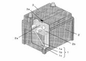
- FIG. 1 is a perspective view showing a lead storage battery of the present invention.
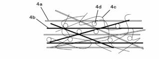
- FIG. 2 is an enlarged schematic view showing the configuration of the separator.
- the lead-acid battery for start-up is mounted on a place where it is easy to replace, and when either phenomenon progresses, the start-up performance gradually decreases and finally the battery life is reached. Therefore, since the customer can easily replace the lead storage battery by detecting the timing of replacement of the lead storage battery due to the deterioration of the starting performance and being installed in a place that is easy to replace, battery deterioration due to these two phenomena is a major problem It does not become.
- lead-acid batteries for start-up since lead-acid batteries for auxiliary equipment are mounted in places where maintenance is difficult, they can withstand long-term use other than unnecessary water replenishment (in view of replacement at automobile inspection Life of more than 3 years) is required. Therefore, a configuration suitable for prolonging the life is taken, such as reducing the amount of lead used as the active material of the positive electrode than that of a general starting lead storage battery.
- the lead storage battery for auxiliary equipment when used for a long time (about 3 years) without maintenance as described above, the phenomenon that the lead storage battery suddenly becomes unusable regardless of the deterioration of the starting performance of the battery occurs. They found it.
- the lead storage battery was disassembled and the cause was examined, it was found that the positive electrode grid itself was expanded to cause a short circuit through the separator. And even if it used the separator described in patent document 1, although the former phenomenon (influence of the refined active material) could be suppressed, it turned out that the latter phenomenon (influence of the expanded positive electrode lattice) can not be suppressed.
- the mat-like separator is a separator made of non-woven fabric or the like whose volume decreases when compressed.
- the main points of overcoming the problem are the following four.
- the mat-like separator is composed of glass fibers, polyester fibers, acrylic fibers, and inorganic powders. This is a configuration common to Patent Document 1.
- Acrylic fibers play the role of a binder for fusing glass fibers and polyester fibers.
- the mass ratio of glass fibers in the separator is A
- the mass ratio of polyester fibers is B
- the mass ratio of acrylic fibers is C
- the mass ratio of inorganic powder is D, 0.2 ⁇ D / ( It is made to satisfy A + B + C + D) ⁇ 0.4.
- the mat-like separator is formed into a bag shape (for example, thermocompression bonding), but at that time, the processability is inferior because the mechanical strength is small with glass fiber alone.
- organic fibers such as polyester fibers are mixed.
- the separator is deteriorated and physically collapsed due to long-term use, and the inorganic powder held inside is dropped, and It was found that the bonding strength between the fibers was reduced, and as a result, the mechanical strength was extremely reduced and the positive electrode grid penetrated the separator to cause an internal short circuit.
- the acrylic fiber which was added in a small amount only for the purpose of expressing the binding function in Patent Document 1, was significantly increased in the present invention, and the retention of the inorganic powder was significantly improved.
- the above-mentioned separator has a configuration in which the liquid level of the electrolyte is higher than the upper end of the electrode plate group (there are more electrolytes than general sealed lead-acid batteries), and the amount of red lead to be included as the active material of the positive electrode is 5 Its performance is effective when it is used for a sealed lead-acid battery having a configuration that enables use over a long period of time, such as a configuration of 10% by mass (the extension of the positive electrode grid increases with the extension of the service life). It is preferable to be able to work.
- the inorganic powder is silica, it has the function of enhancing the water retentivity inside the separator by the water absorbency of the silica, which is preferable. Since diatomaceous earth also has the same function as silica, diatomaceous earth may be used as the inorganic powder.
- FIG. 1 is a perspective view showing a lead storage battery of the present embodiment
- FIG. 2 is a schematic view in which a part of a separator is enlarged.
- the positive electrode 1a and the negative electrode 1b are made to face each other through the mat-like separator 1c to constitute the electrode plate group 1.
- the electrode plate group 1 is housed together with an electrolytic solution (not shown) in each cell chamber 2b of the battery case 2 divided into a plurality of cell chambers 2b by the partition walls 2a, and the lid 3 provided with the control valve 3a By closing the opening of the tank 2, a lead storage battery is configured.
- the positive electrode 1a is configured by filling a positive electrode active material into a positive electrode grid
- the negative electrode 1b is configured by filling a negative electrode active material into a negative electrode grid.
- the separator 1c is composed of glass fibers 4a, polyester fibers 4b, acrylic fibers 4c, and inorganic powder 4d.
- the mass ratio of glass fiber 4a is A
- the mass ratio of polyester fiber 4b is B
- the mass ratio of acrylic fiber 4c is C
- the mass ratio of inorganic powder 4d is D
- a + B + C + D 100, 0.2 It is ⁇ D / (A + B + C + D) ⁇ 0.4 and B ⁇ C and 1.0 ⁇ (B + C) /A ⁇ 1.67.
- Polyester fibers and acrylic fibers are made of a material that is immersed in sulfuric acid and does not deteriorate even if current flows. Specifically, polyester fibers can be exemplified by polyethylene terephthalate (PET) fibers, and acrylic fibers Can be exemplified by polyacrylonitrile fiber.
- PET polyethylene terephthalate
- the present embodiment has the following three features in addition to the fact that the separator 1c is formed of the glass fiber 4a, the polyester fiber 4b, the acrylic fiber 4c, and the inorganic powder 4d.
- the mass ratio of glass fiber 4a is A
- the mass ratio of polyester fiber 4b is B
- the mass ratio of acrylic fiber 4c is C
- the mass ratio of inorganic powder 4d is D
- the positive grid is expanded. Therefore, the inventors found that even if the configuration of the separator 1c is as robust as in Patent Document 1, the expanded positive grid easily penetrates the separator 1c. Then, when the compounding ratio of the inorganic powder 4d with respect to various fibers was made large compared with patent document 1, it discovered that this could be prevented.
- D / (A + B + C + D) is less than 0.2
- the expanded positive electrode grid comes to penetrate the separator 1c by using the lead storage battery for a long time. Conversely, when D / (A + B + C + D) exceeds 0.4, the inorganic powder 4d is excessive, and the mechanical strength of the separator 1c is extremely reduced.
- the mass ratio C of the acrylic fiber 4c is made larger than the mass ratio B of the polyester fiber 4b (B ⁇ C).
- the mat-like separator is formed into a bag (for example, thermocompression bonding) so that the active material dropped from the electrode plate is received in the bag.
- a bag shape only glass fiber 4a has small mechanical strength and is inferior in processability, so organic fibers such as polyester fiber 4b are mixed.
- organic fibers mixed with polyester fiber 4b as in Patent Document 1 In the majority of cases, two problems occur with long-term use. First, the polyester fiber 4b itself is denatured, and the inorganic powder 4d held inside is dropped with it.
- the pore diameter of the separator 1c is increased to cause physical collapse.
- the bonding strength between the glass fiber 4a and the organic fiber (polyester fiber 4b) is reduced.
- the expanded positive electrode grid penetrates the separator 1c whose mechanical strength is extremely reduced, causing an internal short circuit.
- the amount of the fusion binder is significantly increased by significantly increasing the amount of the acrylic fiber 4c, which is added only in a small amount in Patent Document 1, so that the retention of the inorganic powder 4d is significantly improved. It has become possible. Therefore, the pore diameter of the separator 1c can be maintained large to improve the wettability of the electrolytic solution, and it is possible to achieve both of strengthening the bonding strength between the fibers for a long time. As a result, the expanded positive electrode grid can be prevented from easily penetrating the separator 1c. Further, by greatly increasing the proportion of acrylic fibers, when the separator 1c is processed into a bag shape by thermocompression bonding or the like, the seal location is melted smoothly, and the processability is improved.
- this ratio a synergetic effect of the three types of fibers is generated, although details are under investigation, and the retention of the inorganic powder 4d and the pore structure can be optimized.
- the fibers entangle each other and the size and distribution of pores which are gaps between the fibers become uneven, but different kinds of fibers are mixed.
- the acrylic fiber 4c is dispersed so that the binding property of the basic constitution consisting of the glass fiber 4a and the polyester fiber 4b is enhanced. It is possible to form the separator 1c having a structure in which the inorganic powder 4d fills the large pores generated in the basic configuration. Use of such a separator 1c provides the lead-acid battery of the present embodiment that can endure long-term use (without causing sudden discomfort to customers due to sudden incapability) while maintaining the overall characteristics of the battery. become able to.
- the liquid level of the electrolyte is higher than the upper end of the electrode plate group 1 (there are more electrolytes than general sealed lead-acid batteries), and the amount of lead red to be included as the active material of the positive electrode 1a is 5
- the separator according to the present embodiment is a lead-acid battery in which the positive electrode grid is more easily expanded because the use period is extended by incorporating a (long-life) technology that can be used over a long period of time, such as a configuration of 10% by mass. It is preferable to use Red lead has the effect of improving the initial charging efficiency.
- silica as the inorganic powder 4d, since the electrolytic solution is easily held inside the separator 1c by the water absorption of the silica, and the overall characteristics of the battery are improved.
- the positive electrode 1a is formed by casting or expanding a lead alloy made of a Pb-Ca alloy or the like, and applying a paste obtained by kneading a positive electrode active material made of lead powder and red lead and the like with sulfuric acid.
- the negative electrode 1 b is formed by applying a paste obtained by kneading a negative electrode active material made of lead powder and the like with sulfuric acid to a negative electrode grid formed by casting or expanding a lead alloy made of a Pb—Ca alloy.
- Polypropylene can be used as the material of the battery case 2 and the lid 3. A well-known thing can be used for the control valve 3a.
- the positive electrode active material consisting of 92% by mass of lead powder and 8% by mass of red lead was kneaded with sulfuric acid to form a paste.
- This paste was applied to a positive electrode grid formed by expanding a lead alloy made of a Pb—Ca alloy to fabricate a positive electrode 1a. Then, this positive electrode 1a was sandwiched between various mat-like separators 1c shown in (Table 1), and the separator was contained in a bag shape by a thermocompression bonding method.
- the electrode plate group 1 was formed by facing both surfaces of the positive electrode 1a included in the bag-like separator 1c to the negative electrode 1b. Then, the electrode plate group 1 is inserted into each cell chamber 2b of the battery case 2 divided into six cell chambers 2b by the partition walls 2a, and the ear portion corresponding to the upper end of the positive electrode 1a is joined to the positive electrode inside the cell chamber 2b. While being bonded to the member, the ear portion corresponding to the upper end of the negative electrode 1 b was bonded to the negative electrode bonding member.
- the positive electrode bonding member and the negative electrode bonding member of the adjacent cell chamber 2b are bonded via the inter-plate bonding member, and the positive electrode bonding member is a positive electrode terminal that is not bonded to the inter-plate bonding member in the cells at both ends.
- a negative electrode bonding member not bonded to the inter-plate bonding member was bonded to the negative electrode terminal.
- a lead-acid battery denoted as 55D23 in JIS D5301 (commonly referred to as S55D23) was produced.
- the lead storage battery has a height of 202 mm, a width of 173 mm, a length of 232 mm, and a nominal capacity of 43 Ah, excluding the terminals. These are called batteries 1 to 10.
- lead storage batteries fabricated in the same manner as batteries 3 and 5 except that the height of electrode plate group 1 and the liquid surface height of the electrolyte are the same for batteries 3 and 5 are batteries 11 and 12, respectively.
- lead storage batteries fabricated in the same manner as the battery 3 except that the amount of lead red powder to be included as a positive electrode active material is changed with respect to the battery 3 are referred to as batteries 13, 15, 17 and 19.
- lead storage batteries produced in the same manner as the battery 5 except that the amount of lead red powder to be included as a positive electrode active material is changed with respect to the battery 5 are referred to as batteries 14, 16, 18 and 20.
- a lead storage battery produced by changing the mass ratio of polyester fiber to acrylic fiber of the battery 6 to 19: 21 is referred to as a battery 21.
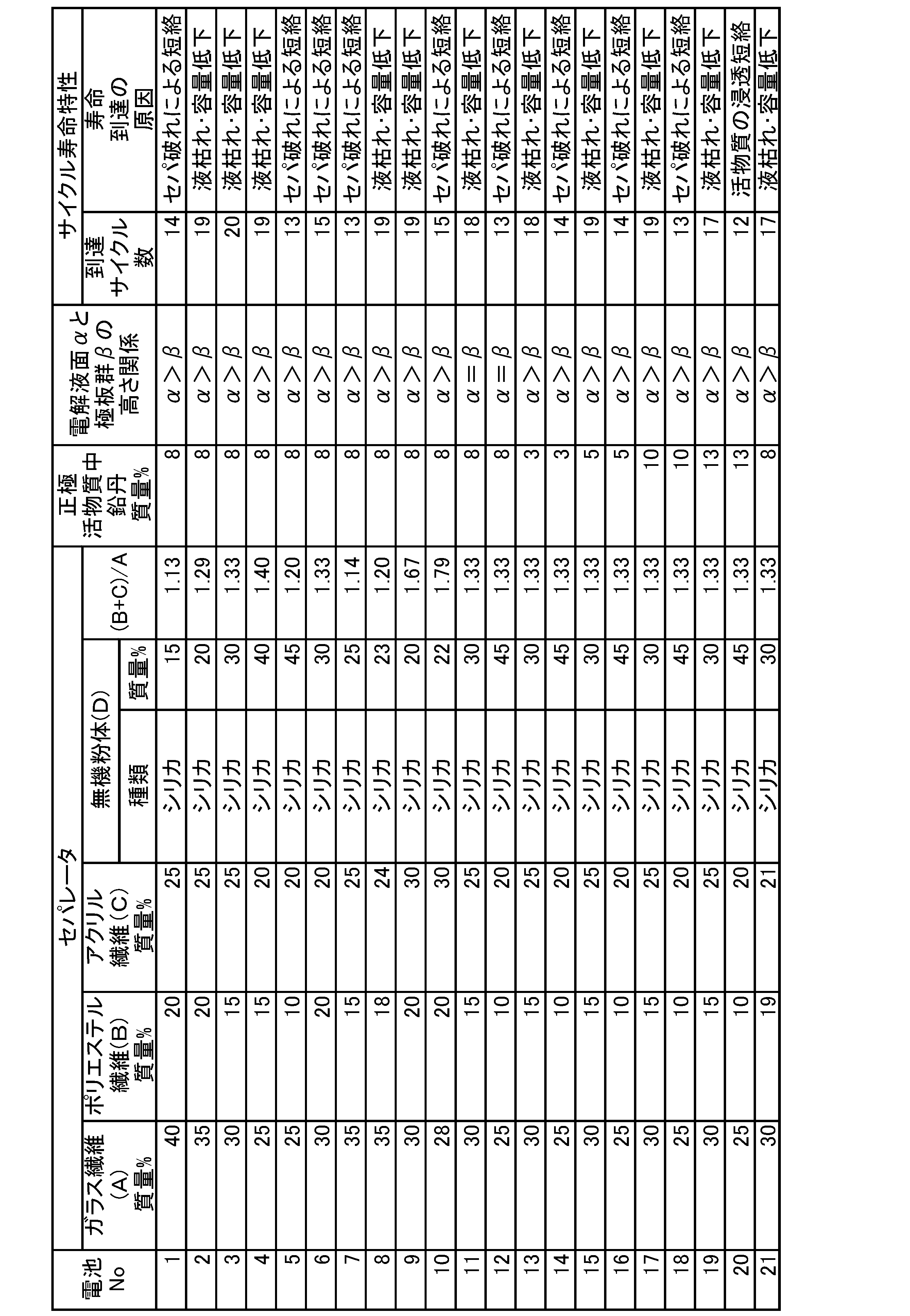
- the above batteries 1 to 21 are subjected to a constant voltage charge of 14.0 V (maximum current 25 A) at 75 ° C. for 120 hours, left for 2 days, and then discharged for 5 seconds at 300 A Did. When the terminal voltage after 5 seconds became 3 V or less, it was judged that each battery had reached the life. The number of cycles that reached the end of the life and the causes of the end of the life clarified by the subsequent decomposition are also described in (Table 1), respectively.
- the ideal lead-acid battery under the high temperature of 75 ° C., the ideal lead-acid battery (high durability of the separator 1c) reaches its life due to a gradual voltage drop due to liquid dead or capacity decrease, and has the conventional problem (
- the lead storage battery with low durability of the separator 1c has reached its life due to a rapid voltage drop due to a short circuit.
- the batteries 2, 3, 4, 8, 9, 11, 13, 15, 17, 19, 21 are the batteries of the embodiment, and the batteries 1, 5, 6, 7, 10, 12, 14, 16, 16 , 20 are batteries of the comparative example.
- the battery of the example has reached the end of life by 17 to 20 cycles due to liquid depletion and a gradual voltage drop due to capacity reduction, and the cell of the comparative example has reached the life of 12 to 15 cycles due to the short circuit.
- the above-mentioned endurance test is conducted at 75 ° C., which is an accelerated test about 10 times the use in a high temperature area (use at about 40 ° C.). Therefore, while the 17 cycles in the example are the number of cycles usable in a high temperature area for 3 years or more, the 15 cycles in the comparative example are the number of cycles that will have a life of less than 3 years. In view of the fact that the maintenance company carries out replacement of the lead storage battery, it can be said that the 15 cycles are not practical and the 17 cycles have characteristics sufficient for practical use.
- the mass ratio of the glass fiber 4a is A
- the mass ratio of the polyester fiber 4b is B
- the batteries 2 to 4, 8 and 9 satisfying /A ⁇ 1.67 resulted in a large number of life cycles.
- the battery 1 in which D / (A + B + C + D) is less than 0.2 rapidly reached the life due to the short circuit.
- D / (A + B + C + D) is less than 0.2 rapidly reached the life due to the short circuit.
- the battery 5 with D / (A + B + C + D) exceeding 0.4 also rapidly reached the life due to the short circuit.
- the positive electrode grid broke the separator 1 c and caused a short circuit. It can be inferred that this is because the mechanical strength of the separator 1 c is extremely reduced because the inorganic powder 4 d (silica) is excessive.
- the battery 6 with B C also rapidly reached the life due to the short circuit.
- the original form of the separator 1c is broken. This is because the polyester fiber 4b is altered and the inorganic powder 4d (silica) falls off from the separator 1c, and the bonding strength between the glass fiber 4a and the polyester fiber 4b is reduced due to the shortage of the acrylic fiber 4c. It can be inferred that it did not melt smoothly (it was difficult to maintain the bag shape from the initial state).
- battery 21 with B: C 19: 21 has 17 cycles and has a long life, and battery performance gradually declines due to liquid shortage and capacity reduction, and battery life is reaching its end. It is easy to make a judgment that it is necessary for a long time.
- both the battery 7 in which (B + C) / A is less than 1.2 and the battery 10 in which (B + C) / A exceeds 1.67 rapidly reach the life due to the short circuit.
- the separator 1c can not maintain the ideal structure as shown in FIG. It can be inferred that the synergetic effect is reduced and not only the short circuit resistance but also the battery characteristics are deteriorated.
- the liquid level of the electrolytic solution is made higher than the upper end of the electrode plate group 1 in order to enable long-term use, and a general sealed type
- the amount of electrolytic solution is larger than that of the lead storage battery, and the amount of red lead to be included as the active material of the positive electrode 1a is 8% by mass.
- the life characteristics are dramatically improved.
- the batteries 15 and 17 (D / (A + B + C + D) within the appropriate range) and the batteries 16 and 18 (D / (A + B + C + D) deviates from the appropriate range).
- the battery 11 (D / (A + B + C + D) is in the appropriate range) and the battery 12 (D / (A + B + C + D) deviates from the appropriate range) whose electrolyte level is the same as the upper end of the electrode group 1 In this case, the degree of improvement of the life characteristics is not as remarkable as the combination described above.
- the batteries 13 and 19 (D / (A + B + C + D) are in the appropriate range) and the batteries 14 and 20 are such that the amount of the red lead to be included as the active material of the positive electrode 1a deviates from the preferable range for prolonging the life. The same applies to comparison with (D / (A + B + C + D) deviates from the appropriate range).
- the fiber can not hold the inorganic powder because the amount of the inorganic powder 4d is too large. This is a result of penetration of the positive electrode active material into the part where 4d is missing, and the battery suddenly becomes unusable as in the case of a short circuit due to the separator being broken, and the useful life for the user is reached.
- the liquid level of the electrolytic solution is made larger than the height of the electrode plate group 1 on the premise of long-term use. It is understood that it is preferable from the viewpoint of prolonging the battery life that it is preferable to weave the configuration or the configuration in which the amount of the lead red powder to be included as the active material of the positive electrode 1a is 5 to 10% by mass.
- the above embodiments and examples are illustrative of the present invention, and the present invention is not limited to these examples.
- the structure and shape of the lead storage battery, the number of cell chambers, etc. are not particularly limited.
- hybrid vehicles are products that suppress global exhaustion due to energy exhaustion and carbon dioxide, they can greatly contribute to the industry by spreading the present invention.
Landscapes
- Chemical & Material Sciences (AREA)
- Electrochemistry (AREA)
- General Chemical & Material Sciences (AREA)
- Chemical Kinetics & Catalysis (AREA)
- Engineering & Computer Science (AREA)
- Inorganic Chemistry (AREA)
- Ceramic Engineering (AREA)
- Composite Materials (AREA)
- Materials Engineering (AREA)
- Manufacturing & Machinery (AREA)
- Cell Separators (AREA)
- Battery Electrode And Active Subsutance (AREA)
- Secondary Cells (AREA)
Abstract
Description
以下に、実施形態について、図を用いて説明する。
上記の実施形態および実施例は本発明の例示であり、本発明はこれらの例に限定されない。ガラス繊維の質量比率A、ポリエステル繊維の質量比率B、アクリル繊維の質量比率C、無機粉体の質量比率Dは、A+B+C+D=100としたときに、0.2≦D/(A+B+C+D)≦0.4、かつB<C、かつ1.2≦(B+C)/A≦1.67を満たしていればどのような配合比率でもよく、実施例の配合比率に限定されない。鉛蓄電池の構造・形状、セル室の数等も特に限定されない。
1a 正極
1b 負極
1c セパレータ
2 電槽
2a 隔壁
2b セル室
3 蓋
3a 制御弁
4a ガラス繊維
4b ポリエステル繊維
4c アクリル繊維
4d 無機粉体
Claims (4)
- 電槽と、
前記電槽を区切って複数のセル室を形成する隔壁と、
それぞれの前記セル室に収納され、セパレータを介して正極板と負極板とを積層した複数の極板群と、
前記セル室に収納される電解液と、
制御弁を備えていると共にそれぞれの前記セル室の開口部を閉じる蓋と
を備えた鉛蓄電池であって、
前記セパレータは、ガラス繊維、ポリエステル繊維、アクリル繊維及び無機粉体を含んだ不織布からなっており、
前記セパレータにおいて、前記ガラス繊維の質量比率をA、前記ポリエステル繊維の質量比率をB、前記アクリル繊維の質量比率をC、前記無機粉体の質量比率をD、A+B+C+D=100としたときに、0.2≦D/(A+B+C+D)≦0.4、かつB<C、かつ1.2≦(B+C)/A≦1.67である、鉛蓄電池。 - 前記蓋が最上部に位置するように鉛蓄電池を設置した場合に、前記電解液の液面が、前記極板群の上端よりも上に位置していることを特徴とする、請求項1記載の鉛蓄電池。
- 前記無機粉体にはシリカが含まれることを特徴とする、請求項1記載の鉛蓄電池。
- 前記正極板の活物質には鉛丹が5質量%以上10質量%未満含まれていることを特徴とする、請求項1記載の鉛蓄電池。
Priority Applications (3)
| Application Number | Priority Date | Filing Date | Title |
|---|---|---|---|
| CN2012800042357A CN103262299A (zh) | 2011-02-01 | 2012-01-25 | 铅蓄电池 |
| DE112012000639T DE112012000639T5 (de) | 2011-02-01 | 2012-01-25 | Bleiakkumulator |
| JP2012555731A JPWO2012105190A1 (ja) | 2011-02-01 | 2012-01-25 | 鉛蓄電池 |
Applications Claiming Priority (2)
| Application Number | Priority Date | Filing Date | Title |
|---|---|---|---|
| JP2011-019476 | 2011-02-01 | ||
| JP2011019476 | 2011-02-01 |
Publications (1)
| Publication Number | Publication Date |
|---|---|
| WO2012105190A1 true WO2012105190A1 (ja) | 2012-08-09 |
Family
ID=46602417
Family Applications (1)
| Application Number | Title | Priority Date | Filing Date |
|---|---|---|---|
| PCT/JP2012/000473 Ceased WO2012105190A1 (ja) | 2011-02-01 | 2012-01-25 | 鉛蓄電池 |
Country Status (4)
| Country | Link |
|---|---|
| JP (1) | JPWO2012105190A1 (ja) |
| CN (1) | CN103262299A (ja) |
| DE (1) | DE112012000639T5 (ja) |
| WO (1) | WO2012105190A1 (ja) |
Families Citing this family (2)
| Publication number | Priority date | Publication date | Assignee | Title |
|---|---|---|---|---|
| JP6442097B1 (ja) * | 2018-03-29 | 2018-12-19 | ニッポン高度紙工業株式会社 | アルミニウム電解コンデンサ用セパレータおよび該セパレータを用いたアルミニウム電解コンデンサ |
| CN119864591B (zh) * | 2024-12-23 | 2026-01-06 | 江苏理士新能源科技有限公司 | 一种高性能铅酸蓄电池agm隔板及其制备方法与应用 |
Citations (6)
| Publication number | Priority date | Publication date | Assignee | Title |
|---|---|---|---|---|
| JPS61128459A (ja) * | 1984-11-28 | 1986-06-16 | Abekawa Seishi Kk | 密閉型鉛蓄電池用セパレ−タ− |
| JPS62180954A (ja) * | 1986-02-03 | 1987-08-08 | Yuasa Battery Co Ltd | 鉛蓄電池用セパレ−タ |
| JP2003297329A (ja) * | 2002-03-31 | 2003-10-17 | Nippon Muki Co Ltd | 密閉型鉛蓄電池用セパレータ |
| JP2004127578A (ja) * | 2002-09-30 | 2004-04-22 | Nippon Muki Co Ltd | 鉛蓄電池用セパレータ |
| JP2005108617A (ja) * | 2003-09-30 | 2005-04-21 | Nippon Sheet Glass Co Ltd | 鉛蓄電池用セパレータ |
| JP2006140033A (ja) * | 2004-11-12 | 2006-06-01 | Matsushita Electric Ind Co Ltd | 鉛蓄電池 |
Family Cites Families (1)
| Publication number | Priority date | Publication date | Assignee | Title |
|---|---|---|---|---|
| JPH0750602B2 (ja) | 1985-09-19 | 1995-05-31 | 松下電器産業株式会社 | 鉛蓄電池 |
-
2012
- 2012-01-25 CN CN2012800042357A patent/CN103262299A/zh active Pending
- 2012-01-25 JP JP2012555731A patent/JPWO2012105190A1/ja active Pending
- 2012-01-25 WO PCT/JP2012/000473 patent/WO2012105190A1/ja not_active Ceased
- 2012-01-25 DE DE112012000639T patent/DE112012000639T5/de not_active Withdrawn
Patent Citations (6)
| Publication number | Priority date | Publication date | Assignee | Title |
|---|---|---|---|---|
| JPS61128459A (ja) * | 1984-11-28 | 1986-06-16 | Abekawa Seishi Kk | 密閉型鉛蓄電池用セパレ−タ− |
| JPS62180954A (ja) * | 1986-02-03 | 1987-08-08 | Yuasa Battery Co Ltd | 鉛蓄電池用セパレ−タ |
| JP2003297329A (ja) * | 2002-03-31 | 2003-10-17 | Nippon Muki Co Ltd | 密閉型鉛蓄電池用セパレータ |
| JP2004127578A (ja) * | 2002-09-30 | 2004-04-22 | Nippon Muki Co Ltd | 鉛蓄電池用セパレータ |
| JP2005108617A (ja) * | 2003-09-30 | 2005-04-21 | Nippon Sheet Glass Co Ltd | 鉛蓄電池用セパレータ |
| JP2006140033A (ja) * | 2004-11-12 | 2006-06-01 | Matsushita Electric Ind Co Ltd | 鉛蓄電池 |
Also Published As
| Publication number | Publication date |
|---|---|
| DE112012000639T5 (de) | 2013-11-14 |
| JPWO2012105190A1 (ja) | 2014-07-03 |
| CN103262299A (zh) | 2013-08-21 |
Similar Documents
| Publication | Publication Date | Title |
|---|---|---|
| KR101831423B1 (ko) | 배터리, 배터리 플레이트 조립체 및 조립 방법 | |
| JP5190562B1 (ja) | エネルギー貯蔵用鉛蓄電池 | |
| JP5867747B2 (ja) | 液式鉛蓄電池 | |
| KR20140144193A (ko) | 리튬 2차 전지용 액 유지체 및 리튬 2차 전지 | |
| JP2011233390A (ja) | 制御弁式鉛蓄電池 | |
| JP2013218894A (ja) | 鉛蓄電池 | |
| JP5182467B2 (ja) | 制御弁式鉛蓄電池の製造方法 | |
| WO2019088040A1 (ja) | 鉛蓄電池用セパレータおよび鉛蓄電池 | |
| CN108028436A (zh) | 铅蓄电池 | |
| JP6205811B2 (ja) | 鉛蓄電池 | |
| JP6592215B1 (ja) | 鉛蓄電池 | |
| CN107112598B (zh) | 铅蓄电池 | |
| WO2012105190A1 (ja) | 鉛蓄電池 | |
| KR20080034409A (ko) | 비대칭 충전 셀들로 구성된 고출력 이차전지 시스템 | |
| JP2004055323A (ja) | 制御弁式鉛蓄電池 | |
| JP2014078325A (ja) | 鉛蓄電池 | |
| JP2018055903A (ja) | 鉛蓄電池用正極板及び鉛蓄電池 | |
| JP5994545B2 (ja) | 鉛蓄電池 | |
| JP6953821B2 (ja) | 液式鉛蓄電池 | |
| WO2020066763A1 (ja) | 鉛蓄電池 | |
| WO2019116704A1 (ja) | 制御弁式鉛蓄電池 | |
| JP2013191351A (ja) | 鉛蓄電池 | |
| WO2021067292A1 (en) | Active material having oxidized fiber additive & electrode and battery having same | |
| KR101641483B1 (ko) | 니켈-아연 포켓 타입 전지의 제조방법 | |
| JP2015153621A (ja) | アルカリ蓄電池 |
Legal Events
| Date | Code | Title | Description |
|---|---|---|---|
| 121 | Ep: the epo has been informed by wipo that ep was designated in this application |
Ref document number: 12742629 Country of ref document: EP Kind code of ref document: A1 |
|
| ENP | Entry into the national phase |
Ref document number: 2012555731 Country of ref document: JP Kind code of ref document: A |
|
| WWE | Wipo information: entry into national phase |
Ref document number: 112012000639 Country of ref document: DE Ref document number: 1120120006399 Country of ref document: DE |
|
| 122 | Ep: pct application non-entry in european phase |
Ref document number: 12742629 Country of ref document: EP Kind code of ref document: A1 |