WO2012105262A1 - Stator de moteur et moteur - Google Patents
Stator de moteur et moteur Download PDFInfo
- Publication number
- WO2012105262A1 WO2012105262A1 PCT/JP2012/000698 JP2012000698W WO2012105262A1 WO 2012105262 A1 WO2012105262 A1 WO 2012105262A1 JP 2012000698 W JP2012000698 W JP 2012000698W WO 2012105262 A1 WO2012105262 A1 WO 2012105262A1
- Authority
- WO
- WIPO (PCT)
- Prior art keywords
- core
- stator
- stator core
- motor
- thin portion
- Prior art date
- Legal status (The legal status is an assumption and is not a legal conclusion. Google has not performed a legal analysis and makes no representation as to the accuracy of the status listed.)
- Ceased
Links
Images




Classifications
-
- H—ELECTRICITY
- H02—GENERATION; CONVERSION OR DISTRIBUTION OF ELECTRIC POWER
- H02K—DYNAMO-ELECTRIC MACHINES
- H02K1/00—Details of the magnetic circuit
- H02K1/06—Details of the magnetic circuit characterised by the shape, form or construction
- H02K1/12—Stationary parts of the magnetic circuit
- H02K1/14—Stator cores with salient poles
- H02K1/146—Stator cores with salient poles consisting of a generally annular yoke with salient poles
- H02K1/148—Sectional cores
-
- H—ELECTRICITY
- H02—GENERATION; CONVERSION OR DISTRIBUTION OF ELECTRIC POWER
- H02K—DYNAMO-ELECTRIC MACHINES
- H02K2213/00—Specific aspects, not otherwise provided for and not covered by codes H02K2201/00 - H02K2211/00
- H02K2213/03—Machines characterised by numerical values, ranges, mathematical expressions or similar information
Definitions
- the present invention relates to a stator and a motor of a permanent magnet brushless motor.
- the strip-shaped core member punched from the core material is laminated, and after winding the winding, the band-shaped core member is bent in an annular shape.
- a stator structure of a connected motor is known (for example, see Patent Document 1).
- a stator of a motor according to the present invention includes a stator core in which a plurality of core pieces are connected and stacked through thin-walled portions, and a plurality of slits are formed on both sides of the thin-walled portion in a stator having a thin-walled portion bent into an annular stator core. Is provided.
- FIG. 1A is a plan view showing a state before the stator core of the permanent magnet brushless motor according to Embodiment 1 of the present invention is bent.
- FIG. 1B is a plan view showing the stator core after bending of the permanent magnet brushless motor according to Embodiment 1 of the present invention.
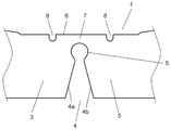
- FIG. 2 is a detailed view showing a V-shaped cutout portion of the stator core of the permanent magnet brushless motor according to Embodiment 1 of the present invention.
- FIG. 3A is a diagram illustrating an analysis calculation result of residual stress after bending a stator core of a conventional permanent magnet brushless motor.
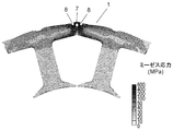
- FIG. 3B is a diagram showing an analysis calculation result of residual stress after the stator core of the permanent magnet brushless motor according to Embodiment 1 of the present invention is bent.
- FIG. 4 is a detailed view showing a V-shaped cutout portion of the stator core of the permanent magnet brushless motor according to Embodiment 2 of the present invention.
- FIG. 1A is a plan view of a permanent magnet brushless motor according to Embodiment 1 of the present invention before the stator core is bent.
- FIG. 1B is a plan view after the stator core of the permanent magnet brushless motor according to Embodiment 1 of the present invention is bent.
- the stator core 1 has a straight core structure in which a plurality of core pieces 3 each having a tooth 2 are stacked in a state of being linearly connected via a thin portion 7.
- the status core 1 is provided with a V-shaped notch 4, and the notch 4 forms a thin portion 7.
- the stator portion 10 of the motor is configured by bending the thin portion 7 to make the stator core 1 annular, and joining the both ends of the status core 1 at the joint 9.
- FIG. 2 is a detailed view of the V-shaped cutout portion of the stator core of the permanent magnet brushless motor according to Embodiment 1 of the present invention.
- the notch 4 is constituted by an end face 4a, an end face 4b, and a substantially arc-shaped notch 5.
- a thin portion 7 that connects the core pieces 3 is formed between the outer periphery 6 on the outer side of the V-shaped cutout 4 and the substantially arc-shaped notch 5.
- Two slits 8 are provided on both sides of the thin portion 7.
- FIG. 3A is a diagram showing an analysis calculation result of a residual stress after bending a stator core of a conventional permanent magnet brushless motor.
- FIG. 3B is a diagram showing an analysis calculation result of residual stress after the stator core of the permanent magnet brushless motor according to Embodiment 1 of the present invention is bent.
- the residual stress Mises stress
- the slits 8 on both sides of the thin portion 7, the force required for bending is reduced. Therefore, the bending process of the stator core 1 can be facilitated, and the deterioration of the iron loss can be suppressed by reducing the core residual stress, and a highly efficient motor can be provided.
- the two slits 8 are preferably provided at substantially target positions in the outer circumferential direction on both sides of the thin portion 7. In this way, the core residual stress can be reduced evenly on both sides of the thin portion 7. Further, the number of slits 8 is not limited to two and may be more than two.
- FIG. 4 is a detailed view of the V-shaped notch portion of the stator core of the permanent magnet brushless motor according to Embodiment 2 of the present invention.
- the stator core 11 of the present embodiment is different from the stator core 1 of the first embodiment only in the slit 18 and the other configuration is the same as that of the first embodiment. The description is omitted.
- the slit 18 in the present embodiment is characterized in that the radial depth h is larger than the radial width t of the thin portion 7.
- the radial direction is a direction orthogonal to the outer periphery of the stator when the thin portion 7 of the status core 11 is bent to form the status core 11 in an annular shape.
- the radial depth h of the slit 18 is larger than the radial width t of the thin portion 7, so that when the stator core 11 is bent, there is no path through which the thin portion 7 extends on both sides in the lateral direction. .
- the stress is less dispersed on the outer periphery, and the stator core 11 is more easily bent.
- the two slits 18 are preferably provided at substantially target positions in the outer circumferential direction on both sides of the thin portion 7. In this way, the core residual stress can be reduced evenly on both sides of the thin portion 7. Further, the number of slits 18 is not limited to two and may be more than two.
- stator described in the first and second embodiments is mounted to constitute a permanent magnet brushless motor, the stator core bending process is facilitated, and the core residual stress is reduced by reducing the core residual stress, A highly efficient motor can be provided.
- the stator core can be easily bent, the residual stress of the core can be greatly reduced, and the iron loss can be reduced, so that a highly efficient motor can be provided.
- the stator of the permanent magnet brushless motor according to the present invention can provide a highly efficient motor by facilitating the bending process of the stator core and reducing the residual stress of the core to suppress the deterioration of iron loss. Suitable for applications that require high efficiency such as home appliances.
Landscapes
- Engineering & Computer Science (AREA)
- Power Engineering (AREA)
- Iron Core Of Rotating Electric Machines (AREA)
Abstract
L'invention concerne un stator de moteur qui est pourvu d'un noyau de stator se présentant sous la forme d'un ensemble de pièces de noyau multiples dentées qui sont reliées par des sections à paroi mince intermédiaires. Les sections à paroi mince du noyau de stator sont courbées pour conférer au noyau de stator une forme d'anneau, et des fentes multiples sont ménagées des deux côtés des sections à paroi mince. Cette configuration permet de réduire la contrainte résiduelle restant dans le noyau de stator et d'obtenir un moteur à haut rendement grâce à l'élimination des pertes dans le fer.
Applications Claiming Priority (2)
| Application Number | Priority Date | Filing Date | Title |
|---|---|---|---|
| JP2011021335 | 2011-02-03 | ||
| JP2011-021335 | 2011-02-03 |
Publications (1)
| Publication Number | Publication Date |
|---|---|
| WO2012105262A1 true WO2012105262A1 (fr) | 2012-08-09 |
Family
ID=46602484
Family Applications (1)
| Application Number | Title | Priority Date | Filing Date |
|---|---|---|---|
| PCT/JP2012/000698 Ceased WO2012105262A1 (fr) | 2011-02-03 | 2012-02-02 | Stator de moteur et moteur |
Country Status (1)
| Country | Link |
|---|---|
| WO (1) | WO2012105262A1 (fr) |
Cited By (3)
| Publication number | Priority date | Publication date | Assignee | Title |
|---|---|---|---|---|
| JP2015015843A (ja) * | 2013-07-05 | 2015-01-22 | 株式会社デンソー | 回転電機の固定子鉄心およびその製造方法 |
| EP3200320B1 (fr) * | 2016-01-28 | 2020-04-29 | Nidec Sankyo Corporation | Stator et son procédé de fabrication |
| WO2021200208A1 (fr) | 2020-03-30 | 2021-10-07 | ダイキン工業株式会社 | Stator et moteur comprenant ledit stator |
Citations (3)
| Publication number | Priority date | Publication date | Assignee | Title |
|---|---|---|---|---|
| JPH11308790A (ja) * | 1998-04-21 | 1999-11-05 | Shibaura Mechatronics Corp | ブラシレスdcモータ |
| JP2010172130A (ja) * | 2009-01-23 | 2010-08-05 | Mitsui High Tec Inc | 積層鉄心及びその製造方法 |
| JP2010288439A (ja) * | 2009-05-15 | 2010-12-24 | Mitsui High Tec Inc | 積層鉄心 |
-
2012
- 2012-02-02 WO PCT/JP2012/000698 patent/WO2012105262A1/fr not_active Ceased
Patent Citations (3)
| Publication number | Priority date | Publication date | Assignee | Title |
|---|---|---|---|---|
| JPH11308790A (ja) * | 1998-04-21 | 1999-11-05 | Shibaura Mechatronics Corp | ブラシレスdcモータ |
| JP2010172130A (ja) * | 2009-01-23 | 2010-08-05 | Mitsui High Tec Inc | 積層鉄心及びその製造方法 |
| JP2010288439A (ja) * | 2009-05-15 | 2010-12-24 | Mitsui High Tec Inc | 積層鉄心 |
Cited By (3)
| Publication number | Priority date | Publication date | Assignee | Title |
|---|---|---|---|---|
| JP2015015843A (ja) * | 2013-07-05 | 2015-01-22 | 株式会社デンソー | 回転電機の固定子鉄心およびその製造方法 |
| EP3200320B1 (fr) * | 2016-01-28 | 2020-04-29 | Nidec Sankyo Corporation | Stator et son procédé de fabrication |
| WO2021200208A1 (fr) | 2020-03-30 | 2021-10-07 | ダイキン工業株式会社 | Stator et moteur comprenant ledit stator |
Similar Documents
| Publication | Publication Date | Title |
|---|---|---|
| KR101679470B1 (ko) | 모터의 적층 코어 및 제조 방법 | |
| US11088577B2 (en) | Permanent magnet synchronous machine and method for manufacturing permanent magnet synchronous machine stator | |
| US9825512B2 (en) | Laminated core manufacturing method | |
| JP5859112B2 (ja) | 回転電機の電機子、及び回転電機の電機子の製造方法 | |
| US9059611B2 (en) | Stator core | |
| WO2011151713A3 (fr) | Rotor d'un moteur électrique et son procédé de fabrication | |
| WO2012160692A1 (fr) | Moteur à aimant permanent | |
| WO2012105261A1 (fr) | Stator de moteur et moteur | |
| JP4562093B2 (ja) | 回転電機および回転電機の製造方法 | |
| WO2016093267A1 (fr) | Procédé de fabrication de stator, procédé de fabrication de machine dynamo-électrique, et bloc de noyau de fer | |
| WO2018062488A1 (fr) | Noyau de rotor, rotor et moteur | |
| WO2018062447A1 (fr) | Rotor et moteur | |
| WO2012105262A1 (fr) | Stator de moteur et moteur | |
| JP6232641B2 (ja) | 固定子鉄心の製造方法 | |
| JP6057777B2 (ja) | 固定子、その固定子を備えた密閉型圧縮機及び回転機並びに金型 | |
| CN202524182U (zh) | 定子铁芯、定子及电机 | |
| JP5528164B2 (ja) | 回転電機のステータ及びその製造方法 | |
| JP6292312B2 (ja) | 回転機及び回転機の製造方法 | |
| JP5278238B2 (ja) | 回転電機 | |
| WO2014136145A1 (fr) | Noyau de stator d'une machine rotative, machine rotative et procédé de fabrication correspondant | |
| US20160226322A1 (en) | Motor Armature | |
| JP2012205489A (ja) | 回転電機の固定子及びその製造方法 | |
| JP4568639B2 (ja) | ステータ | |
| JP2018023232A (ja) | 回転電機および回転電機の製造方法 | |
| US20170222498A1 (en) | Motor Stator and Method for Forming Motor Stator |
Legal Events
| Date | Code | Title | Description |
|---|---|---|---|
| 121 | Ep: the epo has been informed by wipo that ep was designated in this application |
Ref document number: 12742500 Country of ref document: EP Kind code of ref document: A1 |
|
| NENP | Non-entry into the national phase |
Ref country code: DE |
|
| 122 | Ep: pct application non-entry in european phase |
Ref document number: 12742500 Country of ref document: EP Kind code of ref document: A1 |
|
| NENP | Non-entry into the national phase |
Ref country code: JP |