WO2012105265A1 - Systèmes et procédés de codage et de décodage vidéo prenant en charge une fonctionnalité de compatibilité avec des lecteurs vidéo patrimoniaux - Google Patents
Systèmes et procédés de codage et de décodage vidéo prenant en charge une fonctionnalité de compatibilité avec des lecteurs vidéo patrimoniaux Download PDFInfo
- Publication number
- WO2012105265A1 WO2012105265A1 PCT/JP2012/000708 JP2012000708W WO2012105265A1 WO 2012105265 A1 WO2012105265 A1 WO 2012105265A1 JP 2012000708 W JP2012000708 W JP 2012000708W WO 2012105265 A1 WO2012105265 A1 WO 2012105265A1
- Authority
- WO
- WIPO (PCT)
- Prior art keywords
- nal
- unit
- parameter
- avc
- providing
- Prior art date
- Legal status (The legal status is an assumption and is not a legal conclusion. Google has not performed a legal analysis and makes no representation as to the accuracy of the status listed.)
- Ceased
Links
Images












Classifications
-
- H—ELECTRICITY
- H04—ELECTRIC COMMUNICATION TECHNIQUE
- H04N—PICTORIAL COMMUNICATION, e.g. TELEVISION
- H04N19/00—Methods or arrangements for coding, decoding, compressing or decompressing digital video signals
- H04N19/10—Methods or arrangements for coding, decoding, compressing or decompressing digital video signals using adaptive coding
- H04N19/169—Methods or arrangements for coding, decoding, compressing or decompressing digital video signals using adaptive coding characterised by the coding unit, i.e. the structural portion or semantic portion of the video signal being the object or the subject of the adaptive coding
- H04N19/188—Methods or arrangements for coding, decoding, compressing or decompressing digital video signals using adaptive coding characterised by the coding unit, i.e. the structural portion or semantic portion of the video signal being the object or the subject of the adaptive coding the unit being a video data packet, e.g. a network abstraction layer [NAL] unit
-
- H—ELECTRICITY
- H04—ELECTRIC COMMUNICATION TECHNIQUE
- H04N—PICTORIAL COMMUNICATION, e.g. TELEVISION
- H04N19/00—Methods or arrangements for coding, decoding, compressing or decompressing digital video signals
- H04N19/10—Methods or arrangements for coding, decoding, compressing or decompressing digital video signals using adaptive coding
- H04N19/102—Methods or arrangements for coding, decoding, compressing or decompressing digital video signals using adaptive coding characterised by the element, parameter or selection affected or controlled by the adaptive coding
- H04N19/12—Selection from among a plurality of transforms or standards, e.g. selection between discrete cosine transform [DCT] and sub-band transform or selection between H.263 and H.264
-
- H—ELECTRICITY
- H04—ELECTRIC COMMUNICATION TECHNIQUE
- H04N—PICTORIAL COMMUNICATION, e.g. TELEVISION
- H04N19/00—Methods or arrangements for coding, decoding, compressing or decompressing digital video signals
- H04N19/44—Decoders specially adapted therefor, e.g. video decoders which are asymmetric with respect to the encoder
-
- H—ELECTRICITY
- H04—ELECTRIC COMMUNICATION TECHNIQUE
- H04N—PICTORIAL COMMUNICATION, e.g. TELEVISION
- H04N19/00—Methods or arrangements for coding, decoding, compressing or decompressing digital video signals
- H04N19/70—Methods or arrangements for coding, decoding, compressing or decompressing digital video signals characterised by syntax aspects related to video coding, e.g. related to compression standards
Definitions
- Embodiments of the present invention relate to multimedia data coding and, more particularly, to image and video coding utilizing encapsulation of coded data in the Network Abstraction Layer (NAL) to provide compatibility functionality to legacy video players.
- NAL Network Abstraction Layer
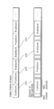
- FIG. 1 shows a diagram illustrating a NAL header 102 of an AVC NAL unit 100 according to the prior art.
- the NAL header 102 includes a one-bit forbidden zero bit 106, a 2-bit NAL reference IDC 108, and a 5-bit NAL unit type 110.
- the 5-bit unit type 110 serves to differentiate the different types of NAL units. There are thus 32 different combinations of the 5-bit unit type 110 which may be used in the NAL header 102.
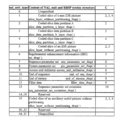
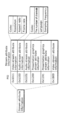
- Figure 2 provides a table identifying the various NAL unit type values that are used in the AVC NAL header 102. As shown in the table, there are only 9 reserved NAL unit type values still available to be used in any future extension of the AVC standard, i.e. bits 14-18 and 20-23.
- New video compression standards including, but not limited to, the High Efficiency Video Coding (HEVC) standard, created after the AVC standard, also encapsulate coded data in NAL units.
- HEVC High Efficiency Video Coding
- New video compression standards will not be the same as the tools used in the AVC standard, various NAL unit type values may be re-assigned to new NAL units created by the new video compression standard.
- a single compressed video stream will include NAL units that contain coded data that are created based on both the AVC standard and on new video compression standards (e.g. HEVC).
- legacy video players using the AVC standard cannot differentiate the AVC NAL units from the HEVC NAL units because they may share the same NAL unit type values, thus resulting in errors in decoding these NAL units.
- the new players that support the HEVC standard cannot differentiate the HEVC NAL units from the AVC NAL units. Thus they will have problems handling a video compression stream in which both AVC NAL units and HEVC NAL units exist.
- NAL unit type values that are reserved in the AVC standard that may be assigned to define the new HEVC NAL units.
- these NAL unit type values are limited and may be required to extend future NAL units that are defined by the AVC standard.
- a new system and method for extending the reserved NAL unit type values of the AVC standard is introduced to define HEVC NAL units.
- the new system and method allow compatibility between the NAL units defined by the HEVC standard and the NAL units defined by the AVC standard.
- One aspect of the present invention provides a system for receiving and encoding video images, the system including: an encoding unit for encoding at least one of a slice of a picture of said video images, a parameter set of said video images, and a supplementary enhancement information of said video image, said encoding step being done according to an Advanced Video Coding (AVC) scheme, or a High Efficiency Video Coding Scheme (HEVC); and a Network Abstraction Layer (NAL) writing unit for writing one or more parameters to an NAL header of said encoded video images and outputting said encoded video images; wherein said outputted encoded video images may be read and decoded by either a standard AVC video decoder or an HEVC video decoder.
- AVC Advanced Video Coding
- HEVC High Efficiency Video Coding Scheme
- the system may further include: a judging unit configured to judge if said coded slice is coded using AVC coding tools or HEVC coding tools; wherein, if said slice is a slice coded using HEVC coding tools, said Network Abstraction Layer (NAL) writing unit further comprises: a setting unit configured to set a NAL reference flag to a predefined value depending on whether said coded slice is a coded slice of a reference picture; a writing unit configured to write said NAL reference flag as one bit in said NAL header; a setting unit configured to set a NAL unit type parameter to a value equal to one of an extended NAL unit type values; and a writing unit configured to write said NAL unit type parameter as six bits in said NAL header.
- NAL Network Abstraction Layer
- the system may further include: a judging unit configured to judge if said coded slice is coded using AVC coding tools or HEVC coding tools; wherein, if said slice is a slice coded using AVC coding tools, said Network Abstraction Layer (NAL) writing unit further comprises: a setting unit configured to set a NAL reference id index parameter to predefined values depending on whether said coded slice is a coded slice of a reference picture; a writing unit configured to write said NAL reference index parameter as two bits in said NAL header; a setting unit configured to set a NAL unit type parameter to a value equal to one of AVC defined NAL unit type values; and a writing unit configured to write said NAL unit type parameter as five bits in said NAL header.
- NAL Network Abstraction Layer
- the system may further include: a judging unit configured to judge if said coded parameter set is an AVC defined parameter set or a HEVC defined parameter set; wherein, if said coded parameter set is a HEVC defined parameter set, said Network Abstraction Layer (NAL) writing unit further comprises: a setting unit configured to set a NAL reference flag to a value of one; a writing unit configured to write said NAL reference flag as one bit in said NAL header; a setting unit configured to set a NAL unit type parameter to a value equal to one of an extended NAL unit type values; and a writing unit configured to write said NAL unit type parameter as six bits in said NAL header.
- NAL Network Abstraction Layer
- the system may further include: a judging unit configured to judge if said coded parameter set is an AVC defined parameter set or a HEVC defined parameter set; wherein, if said coded parameter set is a AVC defined parameter set, said Network Abstraction Layer (NAL) writing unit further comprises: a setting unit configured to set a NAL reference index parameter to a value greater than zero and less than four; a writing unit configured to write said NAL reference index parameter as two bits in a NAL header; a setting unit configured to set a NAL unit type parameter to a value equal to one of AVC defined NAL unit type values; and a writing unit configured to write said NAL unit type parameter as five bits in said NAL header.
- NAL Network Abstraction Layer
- the system may further include: a judging unit configured to judge if said supplementary enhancement information message is an AVC defined supplementary enhancement information message or a HEVC defined supplementary enhancement information message; wherein, if said supplementary enhancement information message is a HEVC defined supplementary enhancement information message, said Network Abstraction Layer (NAL) writing unit further comprises: a setting unit configured to set a NAL reference flag to a value of one; a writing unit configured to write said NAL reference flag as one bit in a NAL header; a setting unit configured to set a NAL unit type parameter to a value equal to one of an extended NAL unit type values; and a writing unit configured to write said NAL unit type parameter as six bits in said NAL header.
- NAL Network Abstraction Layer
- the system may further include: a judging unit configured to judge if said supplementary enhancement information message is an AVC defined supplementary enhancement information message or a HEVC defined supplementary enhancement information message; wherein, if said supplementary enhancement information message is a AVC defined supplementary enhancement information message, said Network Abstraction Layer (NAL) writing unit further comprises: a setting unit configured to set a NAL reference index parameter to a value greater than zero and less than four; a writing unit configured to write said NAL reference index parameter as two bits in a NAL header; a setting unit configured to set a NAL unit type parameter to a value equal to one of AVC defined NAL unit type values; and a writing unit configured to write said NAL unit type parameter as five bits in said NAL header.
- NAL Network Abstraction Layer
- the extended NAL unit type values are reserved NAL unit type values from the AVC standard incremented with a value of thirty two.
- a further aspect of the present invention provides an apparatus for receiving and decoding video images, the apparatus comprising: a parsing unit configured to parse a 6-bit parameter from a NAL unit header of each of said video images; a judging unit configured to judge if said parameter is defined in one of an AVC standard and an HEVC standard; wherein if said parameter is defined in the HEVC standard, said system further comprises a decoding unit configured to decode said NAL unit using the decoding tools from the HEVC standard; and if said parameter is defined in the AVC standard, said system further comprises a decoding unit configured to decode said NAL unit using the decoding tools from the AVC standard.
- said NAL unit may include NAL unit type values from the AVC standard incremented with a value of thirty two.
- a further aspect of the present invention provides a method for receiving and encoding video images, the method including the steps of: providing an encoding unit for encoding at least one of a slice of a picture of said video images, a parameter set of said video images, and a supplementary enhancement information of said video image, said encoding step being done according to an Advanced Video Coding (AVC) scheme, or a High Efficiency Video Coding Scheme (HEVC); and providing a Network Abstraction Layer (NAL) writing unit for writing one or more parameters to an NAL header of said encoded video images and outputting said encoded video images; wherein said outputted encoded video images may be read and decoded by either a standard AVC video decoder or an HEVC video decoder.
- AVC Advanced Video Coding
- HEVC High Efficiency Video Coding Scheme
- the method may further include: providing a judging unit and judging if said coded slice is coded using AVC coding tools or HEVC coding tools; wherein, if said slice is a slice coded using HEVC coding tools, said step of providing said Network Abstraction Layer (NAL) writing unit further comprises: providing a setting unit which sets a NAL reference flag to a predefined value depending on whether said coded slice is a coded slice of a reference picture; providing a writing unit which writes said NAL reference flag as one bit in said NAL header; providing a setting unit which sets a NAL unit type parameter to a value equal to one of an extended NAL unit type values; and providing a writing unit which writes said NAL unit type parameter as six bits in said NAL header.
- NAL Network Abstraction Layer
- the method may further include: providing a judging unit and judging if said coded slice is coded using AVC coding tools or HEVC coding tools; wherein, if said slice is a slice coded using AVC coding tools, said step of providing said Network Abstraction Layer (NAL) writing unit further comprises: providing a setting unit which sets a NAL reference id index parameter to predefined values depending on whether said coded slice is a coded slice of a reference picture; providing a writing unit which writes said NAL reference index parameter as two bits in said NAL header; providing a setting unit which sets a NAL unit type parameter to a value equal to one of AVC defined NAL unit type values; and providing a writing unit which writes said NAL unit type parameter as five bits in said NAL header.
- NAL Network Abstraction Layer
- the method may further include: providing a judging unit which judges if said coded parameter set is an AVC defined parameter set or a HEVC defined parameter set; wherein, if said coded parameter set is a HEVC defined parameter set, said step of providing said Network Abstraction Layer (NAL) writing unit further comprises: providing a setting unit which sets a NAL reference flag to a value of one; providing a writing unit which writes said NAL reference flag as one bit in said NAL header; providing a setting unit which sets a NAL unit type parameter to a value equal to one of an extended NAL unit type values; and providing a writing unit which writes said NAL unit type parameter as six bits in said NAL header.
- NAL Network Abstraction Layer
- the method may further include: providing a judging unit which judges if said coded parameter set is an AVC defined parameter set or a HEVC defined parameter set; wherein, if said coded parameter set is a AVC defined parameter set, said step of providing said Network Abstraction Layer (NAL) writing unit further comprises: providing a setting unit which sets a NAL reference index parameter to a value greater than zero and less than four; providing a writing unit which writes said NAL reference index parameter as two bits in a NAL header; providing a setting unit which sets a NAL unit type parameter to a value equal to one of AVC defined NAL unit type values; and providing a writing unit which writes said NAL unit type parameter as five bits in said NAL header.
- NAL Network Abstraction Layer
- the method may further include: providing a judging unit which judges if said supplementary enhancement information message is an AVC defined supplementary enhancement information message or a HEVC defined supplementary enhancement information message; wherein, if said supplementary enhancement information message is a HEVC defined supplementary enhancement information message, said step of providing said Network Abstraction Layer (NAL) writing unit further comprises: providing a setting unit which sets a NAL reference flag to a value of one; providing a writing unit which writes said NAL reference flag as one bit in a NAL header; providing a setting unit which sets a NAL unit type parameter to a value equal to one of an extended NAL unit type values; and providing a writing unit which writes said NAL unit type parameter as six bits in said NAL header.
- NAL Network Abstraction Layer
- the method may further include: providing a judging unit which judges if said supplementary enhancement information message is an AVC defined supplementary enhancement information message or a HEVC defined supplementary enhancement information message; wherein, if said supplementary enhancement information message is a AVC defined supplementary enhancement information message, said step of providing said Network Abstraction Layer (NAL) writing unit further comprises: providing a setting unit which sets a NAL reference index parameter to a value greater than zero and less than four; providing a writing unit which writes said NAL reference index parameter as two bits in a NAL header; providing a setting unit which sets a NAL unit type parameter to a value equal to one of AVC defined NAL unit type values; and providing a writing unit which writes said NAL unit type parameter as five bits in said NAL header.
- NAL Network Abstraction Layer
- the extended NAL unit type values may be reserved NAL unit type values from the AVC standard incremented with a value of thirty two.
- Figure 1 is a Diagram illustrating a Network Abstraction Layer (NAL) header of an AVC NAL unit
- Figure 2 provides a table identifying NAL Unit Type (NUT) values that are reserved in the AVC NAL header
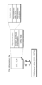
- Figure 3 provides a diagram illustrating a Network Abstraction Layer (NAL) header of an HEVC NAL unit
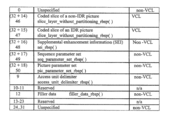
- Figure 4 provides a table identifying extended NAL Unit Type (NUT) values that are designed to be used in the HEVC standard
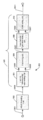
- Figure 5 provides a block diagram illustrating an example apparatus for a video encoder according to embodiments of the current invention
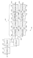
- Figure 6 provides a block diagram illustrating another example apparatus for a video encoder according to embodiments of the current invention
- Figure 7 provides a flowchart showing one embodiment of an encoding process for a slice of a picture according to the current invention
- Figure 8 provides a flowchart showing an alternate embodiment
- Figure 29 provides a drawing showing an example of a look-up table in which the standards of video data are associated with the driving frequencies.
- Figure 30a provides a drawing showing an example of a configuration for sharing a module of a signal processing unit; and
- Figure 30b provides a drawing showing another example of a configuration for sharing a module of a signal processing unit.
- a new system and method for extending the reserved NAL unit type values of the AVC standard is introduced to define HEVC NAL units.
- the new system and method allow compatibility between the NAL units defined by the HEVC standard and the NAL units defined by the AVC standard.
- Embodiments of the present invention thus extend the remaining NAL unit type values that were reserved in the AVC standard by increasing the NAL unit type parameter from 5 bits to 6 bits in the NAL header, and setting the additional bit to a value of one.
- the extended NAL unit type values are still decoded as reserved NAL units to the legacy AVC decoders, the legacy AVC decoders will ignore the new HEVC NAL units, thus avoiding any decoding errors and achieving some form of backward compatibility.
- the HEVC NAL units are defined starting from the extended NAL unit type values, the previously reserved AVC NAL units are still available for the future extension of both the AVC standard and the HEVC standard.
- FIG. 3 shows a diagram illustrating a Network Abstraction Layer (NAL) header 130 of an HEVC NAL unit as used in embodiments of the current invention.
- the NAL header 130 for HEVC NAL units includes a 1-bit forbidden_zero_bit 132, a 1-bit NAL reference idc 134, and a 6-bit NAL unit type 136.
- the 6-bit NAL unit type 136 is coded in the NAL header 130 to differentiate different types of NAL units, including HEVC NAL units and AVC NAL units.
- Figure 4 shows a table identifying the extended NAL unit type values that, at the time of this writing, are assigned to be used for HEVC NAL units for compatibility.
- the new extended NAL unit type values assigned for HEVC NAL units are values computed by the sum of the value thirty-two and one of the AVC reserved NAL unit type values.
- the nal_ref_idc for the AVC decoder is set to a value of 1
- the HEVC unit types are equivalent to the AVC unit types plus a value of 32.
- these nal_unit_types can be commonly defined for both AVC and HEVC encoders/decoders. This will be discussed in more detail below.
- NAL units may be classified into Video Coding Layer (VCL) and non-VCL NAL units.
- VCL NAL units contain the data that represents the values of the samples in the video pictures
- non-VCL NAL units contain any associated additional information such as parameter sets (important header data that can apply to a large number of VCL NAL units) and supplemental enhancement information (timing information and other supplemental data that may enhance usability of the decoded video signal but are not necessary for decoding the values of the samples in the video pictures).
- FIG. 5 provides a block diagram illustrating an example system 500 for a video encoder according to embodiments of the current invention.
- the system 500 may include a video encoding unit 502 implemented based on the HEVC standard, and a NAL writing unit 520 for writing one or more parameters to an NAL header of the encoded video images, then outputting the encoded video images.
- the NAL writing unit 520 may include a 1-bit NAL reference flag value setting unit 504, a 1-bit flag writing unit 506, a 6-bit NAL unit type value setting unit 508 and a 6-bit writing unit 510. It is understood that various other configurations of the NAL writing unit may also be used.
- the HEVC video encoding unit 502 may read a picture D501 and output a NAL unit D503 encapsulating either a coded slice of a picture, a parameter set or a SEI (supplementary enhancement information) message to the 1 bit NAL reference flag value setting unit 504. Specific implementation of each of these embodiments is discussed below with reference to Figures 7-9.
- the setting unit 504 sets a reference flag value, sends the flag value D505 and the NAL unit D503 to the flag writing unit 506.
- the flag writing unit 506 writes the NAL reference flag value into the header of the NAL unit and sends the NAL unit D507 to the NAL unit type value setting unit 508.
- the NAL unit type value setting unit 508 then reads the NAL unit D507, determines the type of NAL unit and outputs the 6-bit NAL unit type value D509 to the writing unit 510 together with NAL unit D507.
- the writing unit 510 will then write the 6-bit NAL unit type value into the header of the NAL unit, and outputs the NAL unit D511 as part of the coded video.
- a coded slice of a picture contains residual samples information required to reconstruct image samples of a picture.
- a parameter set contains a plurality of parameters required to parse and to decode a coded slice.
- Some examples of parameter sets are sequence parameter sets (containing parameters required for a group of pictures), picture parameter sets (containing parameters required for a plurality of slices) etc. It is understood that parameter sets may include additional features not specifically described herein.
- a SEI message contains parameters that provide additional information regarding the coded picture or video but are not required for the parsing or decoding of a coded slice. There is no specific position or order to which a coded slice, a SEI message or a parameter set should be present in a coded video stream. However prior to the parsing or decoding of a coded slice, it is desirable that the parameter set containing parameters required for the parsing of the coded slice be positioned or parsed before the coded slice.
- Figure 6 provides a block diagram illustrating another example system/apparatus 600 for a video encoder according to embodiments of the present invention.
- the apparatus 600 may include a video encoding unit 602, a judging unit 604, a switching unit 606, and a NAL writing unit 610.
- the NAL writing unit 610 may further include a NAL reference flag value setting unit 612, a 1-bit flag writing unit 614, a 6-bit NAL unit type value setting unit 616, a 6-bit writing unit 618, a NAL reference index value setting unit 620, a 2-bit writing unit 622 for NAL reference index, a 5-bit NAL unit type value setting unit 624 and a writing unit 628 for a 5-bit NAL unit type. It is understood that other configurations of the NAL writing unit may also be used.
- the video encoding unit 602 may include the capability to encode various aspects of video images based on both the HEVC standard and the AVC standard.
- the video encoding unit 602 reads a picture D601 and outputs a NAL unit D603 encapsulating either a coded slice of a picture, a parameter set or a SEI (supplementary enhancement information) message to judging unit 604.
- the judging unit 604 reads the NAL unit D603 and outputs a control signal D605 to control the switching unit 606 depending on whether the NAL unit is a AVC NAL unit or a HEVC NAL unit.
- the switching unit 606 will then send the NAL unit D603 to either the NAL reference flag setting unit 612, shown as D607, or the NAL reference index setting unit 620, shown as D609.
- the NAL reference flag setting unit 612 sets a reference flag value, sends the flag value D611 and the NAL unit D607 to the flag writing unit 614.
- the flag writing unit 614 writes the NAL reference flag value into the header of the NAL unit and sends the NAL unit D615 to the NAL unit type value setting unit 616.
- the NAL unit type value setting unit 616 then reads the NAL unit D615, determines the type of NAL unit and outputs the 6-bit NAL unit type value D619 to the writing unit 618 together with NAL unit D615.
- the 6 bit writing unit 618 will then write the 6-bit NAL unit type value D619 into the header of the NAL unit D629, and outputs the complete NAL unit D623 as part of the coded video.
- the switching unit 606 sends the NAL unit D609 to the NAL reference index setting unit 620, which sets a reference index value, sends the index value D613 and the NAL unit D609 to the 2-bit reference index writing unit 622.
- the reference index writing unit 622 writes the NAL reference index value into the header of the NAL unit and sends the NAL unit D617 to the 5-bit NAL unit type value setting unit 624.
- the 5-bit NAL unit type value setting unit 624 then reads the NAL unit D617, determines the type of NAL unit and outputs the 5-bit NAL unit type value D621 to the writing unit 628 together with NAL unit D617.
- the writing unit 628 will then write the 5-bit NAL unit type value D621 into the header of the NAL unit and outputs the NAL unit D625 as part of the coded video.
- Figures 7-9 show various embodiments of an encoding process that can be used with the systems 500/600 described above.
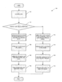
- Figure 7 provides a flow chart, designated generally as reference numeral 700, showing an encoding process for a slice of a picture according to an embodiment.
- a slice is encoded in module 701.
- the slice may be coded using coding tools from the AVC standard or coding tools from the HEVC standard.
- the coded slice is judged as to whether it is a slice coded using the coding tools in HEVC or the AVC standard.
- a nal_ref_idc parameter is set to a value of zero if the coded slice is not a coded slide of a reference picture.
- the nal_ref_idc parameter is set to a value of one if the coded slice is a coded slice of a reference picture, as shown in module 704.
- the nal_ref_idc parameter is written as one bit in the NAL header, as shown in module 706.
- a NAL unit type parameter is then set to one of the extended NAL unit type values, as shown in module 708.
- the extended NAL unit type values are the AVC reserved NAL unit type values plus a value of thirty-two.
- the 6-bit NAL unit type value is written into the NAL header, as shown in module 710.
- a nal_ref_idc parameter is set to a value of zero. If the coded slice is not a coded slide of a reference picture the nal_ref_idc parameter is set to a non-zero value, as shown in module 712. The next step is the writing of the nal_ref_idc parameter as two bits in the NAL header, as shown in module 714, and setting a NAL unit type parameter to one of the AVC standard defined NAL unit type values as shown in module 716. Then in module 718, the five bits NAL unit type value is written into the NAL header.
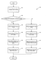
- Figure 8 is a flow chart, designated generally with reference numeral 800, showing an encoding process for a parameter set according to an embodiment of the present invention.
- the parameter set can be either a sequence parameter set or a picture parameter set.
- a parameter set is encoded in module 801.
- the parameter set may either include parameters from the AVC standard or parameters from the HEVC standard.
- the parameter set is judged as to which of the standards are used.
- a nal_ref_idc parameter is set to a value of one, as shown in module 804.
- the nal_ref_idc parameter is then written as one bit in the NAL header, as shown in module 806.
- a NAL unit type parameter is then set to one of the extended NAL unit type values, as shown in module 808.
- the extended NAL unit type values are the AVC reserved NAL unit type values plus a value of thirty-two.
- the six bits NAL unit type value is written into the NAL header, as shown in module 810.
- a nal_ref_idc parameter is set to a value greater than zero, as shown in module 812.
- the nal_ref_idc parameter is then written as two bits in the NAL header, as shown in module 814.
- a NAL unit type parameter is then set to one of the AVC standard defined NAL unit type values, as shown in module 816. Finally, the 5-bit NAL unit type value is written into the NAL header, as shown in module 818.
- FIG. 9 provides a flow chart, designated generally with reference numeral 900, showing an encoding process for a Supplementary Enhancement Information (SEI) message according to embodiments of the current invention.
- SEI Supplementary Enhancement Information
- a SEI message is encoded in module 901.
- the SEI message is then judged as to whether or not it is a new message defined in the HEVC standard, as shown in module 902.
- a nal_ref_idc parameter is set to a value of zero, as shown in module 904.
- the nal_ref_idc parameter is then written as one bit in the NAL header, as shown in module 906.
- a NAL unit type parameter is then set to one of the extended NAL unit type values, as shown in module 908.
- the extended NAL unit type values are the AVC reserved NAL unit type values plus a value of thirty-two.
- the six bits NAL unit type value is then written into the NAL header, as shown in module 910.
- a nal_ref_idc parameter is set to a value equal to zero, as shown in module 912.
- the nal_ref_idc parameter is then written as two bits in the NAL header, as shown in module 914.
- a NAL unit type parameter is then set to one of the AVC standard defined NAL unit type values, as shown in module 916. Finally, the 5-bit NAL unit type value is written into the NAL header, as shown in module 918.
- Figure 10 provides a block diagram illustrating an example system/apparatus, designated generally as reference numeral 750, for a video decoder according to embodiments of the current invention.
- the system/apparatus may include a NAL unit type parameter parsing unit 760, a judging unit 762, a switch unit 764, an AVC video decoder 766 and a HEVC video decoder 768.
- the NAL unit type parameter parsing unit 760 reads a NAL unit D751 and parses a NAL unit type parameter D753 from the NAL unit.
- the judging unit 762 will read the parsed NAL unit type parameter D753, judge whether the NAL unit is a HEVC NAL unit or an AVC NAL unit, and sends a control signal D755 to the switch unit 764.
- the switch unit 764 will then connect the NAL unit D751 to either the AVC video decoder 766 or the HEVC video decoder 768, depending on input from the control signal D755.
- the decoder units 766, 768 will decode the NAL unit and output a picture D761.
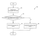
- Figure 11 is flowchart, designated generally with reference numeral 780, showing one embodiment of a decoding process for a NAL unit according to the current invention.
- a 6-bit NAL unit type parameter is parsed from a NAL header.
- the NAL unit type parameter is judged to determine whether or not it is one of the extended NAL unit types defined in the HEVC standard. If the NAL unit type parameter is one of the extended NAL unit types defined in the HEVC NAL unit types, the NAL unit is decoded using a decoder implemented based on decoding tools from the HEVC standard, as shown in module 788. Otherwise, if the NAL unit type parameter is not one of the extended NAL unit types defined in HEVC standard, the NAL unit is decoded using a decoder implemented based on decoding tools from the AVC standard, as shown in module 788.
- Embodiment 8 The processing described in each of Embodiments can be simply implemented in an independent computer system, by recording, in a recording medium, a program for implementing the configurations of the video coding method and the video decoding method described in each of Embodiments.
- the recording media may be any recording media as long as the program can be recorded, such as a magnetic disk, an optical disk, a magnetic optical disk, an IC card, and a semiconductor memory.
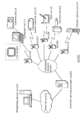
- Figure 12 illustrates an overall configuration of a content providing system ex100 for implementing content distribution services.
- the area for providing communication services is divided into cells of desired size, and base stations ex106, ex107, ex108, ex109, and ex110 which are fixed wireless stations are placed in each of the cells.
- the content providing system ex100 is connected to devices, such as a computer ex111, a personal digital assistant (PDA) ex112, a camera ex113, a cellular phone ex114 and a game machine ex115, via the Internet ex101, an Internet service provider ex102, a telephone network ex104, as well as the base stations ex106 to ex110, respectively.
- devices such as a computer ex111, a personal digital assistant (PDA) ex112, a camera ex113, a cellular phone ex114 and a game machine ex115, via the Internet ex101, an Internet service provider ex102, a telephone network ex104, as well as the base stations ex106 to ex110, respectively.
- each device may be directly connected to the telephone network ex104, rather than via the base stations ex106 to ex110 which are the fixed wireless stations.
- the devices may be interconnected to each other via a short distance wireless communication and others.
- the camera ex113 such as a digital video camera
- a camera ex116 such as a digital video camera
- the cellular phone ex114 may be the one that meets any of the standards such as Global System for Mobile Communications (GSM), Code Division Multiple Access (CDMA), Wideband-Code Division Multiple Access (W-CDMA), Long Term Evolution (LTE), and High Speed Packet Access (HSPA).
- GSM Global System for Mobile Communications
- CDMA Code Division Multiple Access
- W-CDMA Wideband-Code Division Multiple Access
- LTE Long Term Evolution
- HSPA High Speed Packet Access
- the cellular phone ex114 may be a Personal Handyphone System (PHS).
- PHS Personal Handyphone System
- a streaming server ex103 is connected to the camera ex113 and others via the telephone network ex104 and the base station ex109, which enables distribution of images of a live show and others.
- a content for example, video of a music live show
- the streaming server ex103 carries out stream distribution of the transmitted content data to the clients upon their requests.
- the clients include the computer ex111, the PDA ex112, the camera ex113, the cellular phone ex114, and the game machine ex115 that are capable of decoding the above-mentioned coded data.
- Each of the devices that have received the distributed data decodes and reproduces the coded data.
- the captured data may be coded by the camera ex113 or the streaming server ex103 that transmits the data, or the coding processes may be shared between the camera ex113 and the streaming server ex103.
- the distributed data may be decoded by the clients or the streaming server ex103, or the decoding processes may be shared between the clients and the streaming server ex103.
- the data of the still images and video captured by not only the camera ex113 but also the camera ex116 may be transmitted to the streaming server ex103 through the computer ex111.
- the coding processes may be performed by the camera ex116, the computer ex111, or the streaming server ex103, or shared among them.
- the coding and decoding processes may be performed by an LSI ex500 generally included in each of the computer ex111 and the devices.
- the LSI ex500 may be configured of a single chip or a plurality of chips.
- Software for coding and decoding video may be integrated into some type of a recording medium (such as a CD-ROM, a flexible disk, and a hard disk) that is readable by the computer ex111 and others, and the coding and decoding processes may be performed using the software.
- a recording medium such as a CD-ROM, a flexible disk, and a hard disk
- the coding and decoding processes may be performed using the software.
- the image data obtained by the camera may be transmitted.
- the video data is data coded by the LSI ex500 included in the cellular phone ex114.
- the streaming server ex103 may be composed of servers and computers, and may decentralize data and process the decentralized data, record, or distribute data.
- the clients may receive and reproduce the coded data in the content providing system ex100.
- the clients can receive and decode information transmitted by the user, and reproduce the decoded data in real time in the content providing system ex100, so that the user who does not have any particular right and equipment can implement personal broadcasting.
- a broadcast station ex201 communicates or transmits, via radio waves to a broadcast satellite ex202, multiplexed data obtained by multiplexing audio data and others onto video data.
- the video data is data coded by the video coding method described in each of Embodiments.
- the broadcast satellite ex202 Upon receipt of the multiplexed data, the broadcast satellite ex202 transmits radio waves for broadcasting. Then, a home-use antenna ex204 with a satellite broadcast reception function receives the radio waves.
- a device such as a television (receiver) ex300 and a set top box (STB) ex217 decodes the received multiplexed data, and reproduces the decoded data.
- a device such as a television (receiver) ex300 and a set top box (STB) ex217 decodes the received multiplexed data, and reproduces the decoded data.
- STB set top box
- a reader/recorder ex218 (i) reads and decodes the multiplexed data recorded on a recording media ex215, such as a DVD and a BD, or (i) codes video signals in the recording medium ex215, and in some cases, writes data obtained by multiplexing an audio signal on the coded data.
- the reader/recorder ex218 can include the video decoding apparatus or the video coding apparatus as shown in each of Embodiments. In this case, the reproduced video signals are displayed on the monitor ex219, and can be reproduced by another device or system using the recording medium ex215 on which the multiplexed data is recorded.
- the video decoding apparatus in the set top box ex217 connected to the cable ex203 for a cable television or to the antenna ex204 for satellite and/or terrestrial broadcasting, so as to display the video signals on the monitor ex219 of the television ex300.
- the video decoding apparatus may be implemented not in the set top box but in the television ex300.
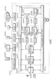
- FIG 14 illustrates the television (receiver) ex300 that uses the video coding method and the video decoding method described in each of Embodiments.
- the television ex300 includes: a tuner ex301 that obtains or provides multiplexed data obtained by multiplexing audio data onto video data, through the antenna ex204 or the cable ex203, etc. that receives a broadcast; a modulation/demodulation unit ex302 that demodulates the received multiplexed data or modulates data into multiplexed data to be supplied outside; and a multiplexing/demultiplexing unit ex303 that demultiplexes the modulated multiplexed data into video data and audio data, or multiplexes video data and audio data coded by a signal processing unit ex306 into data.
- the television ex300 further includes: a signal processing unit ex306 including an audio signal processing unit ex304 and a video signal processing unit ex305 that decode audio data and video data and code audio data and video data, respectively; and an output unit ex309 including a speaker ex307 that provides the decoded audio signal, and a display unit ex308 that displays the decoded video signal, such as a display.
- the television ex300 includes an interface unit ex317 including an operation input unit ex312 that receives an input of a user operation.
- the television ex300 includes a control unit ex310 that controls overall each constituent element of the television ex300, and a power supply circuit unit ex311 that supplies power to each of the elements.
- the interface unit ex317 may include: a bridge ex313 that is connected to an external device, such as the reader/recorder ex218; a slot unit ex314 for enabling attachment of the recording medium ex216, such as an SD card; a driver ex315 to be connected to an external recording medium, such as a hard disk; and a modem ex316 to be connected to a telephone network.
- the recording medium ex216 can electrically record information using a non-volatile/volatile semiconductor memory element for storage.
- the constituent elements of the television ex300 are connected to each other through a synchronous bus.
- the television ex300 decodes multiplexed data obtained from outside through the antenna ex204 and others and reproduces the decoded data
- the multiplexing/demultiplexing unit ex303 demultiplexes the multiplexed data demodulated by the modulation/demodulation unit ex302, under control of the control unit ex310 including a CPU.
- the audio signal processing unit ex304 decodes the demultiplexed audio data
- the video signal processing unit ex305 decodes the demultiplexed video data, using the decoding method described in each of Embodiments, in the television ex300.
- the output unit ex309 provides the decoded video signal and audio signal outside, respectively.
- the signals may be temporarily stored in buffers ex318 and ex319, and others so that the signals are reproduced in synchronization with each other.
- the television ex300 may read multiplexed data not through a broadcast and others but from the recording media ex215 and ex216, such as a magnetic disk, an optical disk, and a SD card. Next, a configuration in which the television ex300 codes an audio signal and a video signal, and transmits the data outside or writes the data on a recording medium will be described.
- the audio signal processing unit ex304 codes an audio signal
- the video signal processing unit ex305 codes a video signal, under control of the control unit ex310 using the coding method described in each of Embodiments.
- the multiplexing/demultiplexing unit ex303 multiplexes the coded video signal and audio signal, and provides the resulting signal outside.
- the signals may be temporarily stored in the buffers ex320 and ex321, and others so that the signals are reproduced in synchronization with each other.
- the buffers ex318, ex319, ex320, and ex321 may be plural as illustrated, or at least one buffer may be shared in the television ex300. Furthermore, data may be stored in a buffer so that the system overflow and underflow may be avoided between the modulation/demodulation unit ex302 and the multiplexing/demultiplexing unit ex303, for example.
- the television ex300 may include a configuration for receiving an AV input from a microphone or a camera other than the configuration for obtaining audio and video data from a broadcast or a recording medium, and may code the obtained data.
- the television ex300 can code, multiplex, and provide outside data in the description, it may be capable of only receiving, decoding, and providing outside data but not the coding, multiplexing, and providing outside data.
- the reader/recorder ex218 when the reader/recorder ex218 reads or writes multiplexed data from or on a recording medium, one of the television ex300 and the reader/recorder ex218 may decode or code the multiplexed data, and the television ex300 and the reader/recorder ex218 may share the decoding or coding.
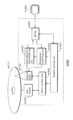
- Figure 15 illustrates a configuration of an information reproducing/recording unit ex400 when data is read or written from or on an optical disk.
- the information reproducing/recording unit ex400 includes constituent elements ex401, ex402, ex403, ex404, ex405, ex406, and ex407 to be described hereinafter.
- the optical head ex401 irradiates a laser spot in a recording surface of the recording medium ex215 that is an optical disk to write information, and detects reflected light from the recording surface of the recording medium ex215 to read the information.
- the modulation recording unit ex402 electrically drives a semiconductor laser included in the optical head ex401, and modulates the laser light according to recorded data.
- the reproduction demodulating unit ex403 amplifies a reproduction signal obtained by electrically detecting the reflected light from the recording surface using a photo detector included in the optical head ex401, and demodulates the reproduction signal by separating a signal component recorded on the recording medium ex215 to reproduce the necessary information.
- the buffer ex404 temporarily holds the information to be recorded on the recording medium ex215 and the information reproduced from the recording medium ex215.
- the disk motor ex405 rotates the recording medium ex215.
- the servo control unit ex406 moves the optical head ex401 to a predetermined information track while controlling the rotation drive of the disk motor ex405 so as to follow the laser spot.
- the system control unit ex407 controls overall the information reproducing/recording unit ex400.
- the reading and writing processes can be implemented by the system control unit ex407 using various information stored in the buffer ex404 and generating and adding new information as necessary, and by the modulation recording unit ex402, the reproduction demodulating unit ex403, and the servo control unit ex406 that record and reproduce information through the optical head ex401 while being operated in a coordinated manner.
- the system control unit ex407 includes, for example, a microprocessor, and executes processing by causing a computer to execute a program for read and write.
- the optical head ex401 may perform high-density recording using near field light.
- Figure 16 illustrates the recording medium ex215 that is the optical disk.
- an information track ex230 records, in advance, address information indicating an absolute position on the disk according to change in a shape of the guide grooves.
- the address information includes information for determining positions of recording blocks ex231 that are a unit for recording data. Reproducing the information track ex230 and reading the address information in an apparatus that records and reproduces data can lead to determination of the positions of the recording blocks.
- the recording medium ex215 includes a data recording area ex233, an inner circumference area ex232, and an outer circumference area ex234.
- the data recording area ex233 is an area for use in recording the user data.
- the inner circumference area ex232 and the outer circumference area ex234 that are inside and outside of the data recording area ex233, respectively are for specific use except for recording the user data.
- the information reproducing/recording unit 400 reads and writes coded audio, coded video data, or multiplexed data obtained by multiplexing the coded audio and video data, from and on the data recording area ex233 of the recording medium ex215.
- optical disk having a layer such as a DVD and a BD
- the optical disk is not limited to such, and may be an optical disk having a multilayer structure and capable of being recorded on a part other than the surface.
- the optical disk may have a structure for multidimensional recording/reproduction, such as recording of information using light of colors with different wavelengths in the same portion of the optical disk and for recording information having different layers from various angles.
- a car ex210 having an antenna ex205 can receive data from the satellite ex202 and others, and reproduce video on a display device such as a car navigation system ex211 set in the car ex210, in the digital broadcasting system ex200.
- a configuration of the car navigation system ex211 will be a configuration, for example, including a GPS receiving unit from the configuration illustrated in FIG. 9. The same will be true for the configuration of the computer ex111, the cellular phone ex114, and others.
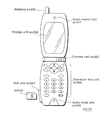
- FIG 17a illustrates the cellular phone ex114 that uses the video coding method and the video decoding method described in Embodiments.
- the cellular phone ex114 includes: an antenna ex350 for transmitting and receiving radio waves through the base station ex110; a camera unit ex365 capable of capturing moving and still images; and a display unit ex358 such as a liquid crystal display for displaying the data such as decoded video captured by the camera unit ex365 or received by the antenna ex350.
- the cellular phone ex114 further includes: a main body unit including an operation key unit ex366; an audio output unit ex357 such as a speaker for output of audio; an audio input unit ex356 such as a microphone for input of audio; a memory unit ex367 for storing captured video or still pictures, recorded audio, coded or decoded data of the received video, the still pictures, e-mails, or others; and a slot unit ex364 that is an interface unit for a recording medium that stores data in the same manner as the memory unit ex367.
- a main body unit including an operation key unit ex366; an audio output unit ex357 such as a speaker for output of audio; an audio input unit ex356 such as a microphone for input of audio; a memory unit ex367 for storing captured video or still pictures, recorded audio, coded or decoded data of the received video, the still pictures, e-mails, or others; and a slot unit ex364 that is an interface unit for a recording medium that stores data in the same manner as
- a main control unit ex360 designed to control overall each unit of the main body including the display unit ex358 as well as the operation key unit ex366 is connected mutually, via a synchronous bus ex370, to a power supply circuit unit ex361, an operation input control unit ex362, a video signal processing unit ex355, a camera interface unit ex363, a liquid crystal display (LCD) control unit ex359, a modulation/demodulation unit ex352, a multiplexing/ demultiplexing unit ex353, an audio signal processing unit ex354, the slot unit ex364, and the memory unit ex367.
- a power supply circuit unit ex361 an operation input control unit ex362
- a video signal processing unit ex355 a camera interface unit ex363, a liquid crystal display (LCD) control unit ex359
- a modulation/demodulation unit ex352 a multiplexing/ demultiplexing unit ex353, an audio signal processing unit ex354, the slot unit ex364, and the memory unit ex367.
- LCD liquid crystal display
- the power supply circuit unit ex361 supplies the respective units with power from a battery pack so as to activate the cell phone ex114.
- the audio signal processing unit ex354 converts the audio signals collected by the audio input unit ex356 in voice conversation mode into digital audio signals under the control of the main control unit ex360 including a CPU, ROM, and RAM. Then, the modulation/demodulation unit ex352 performs spread spectrum processing on the digital audio signals, and the transmitting and receiving unit ex351 performs digital-to-analog conversion and frequency conversion on the data, so as to transmit the resulting data via the antenna ex350.
- the transmitting and receiving unit ex351 amplifies the data received by the antenna ex350 in voice conversation mode and performs frequency conversion and the analog-to-digital conversion on the data. Then, the modulation/demodulation unit ex352 performs inverse spread spectrum processing on the data, and the audio signal processing unit ex354 converts it into analog audio signals, so as to output them via the audio output unit ex356.
- the video signal processing unit ex355 compresses and codes video signals supplied from the camera unit ex365 using the video coding method shown in each of Embodiments, and transmits the coded video data to the multiplexing/demultiplexing unit ex353.
- the audio signal processing unit ex354 codes audio signals collected by the audio input unit ex356, and transmits the coded audio data to the multiplexing/demultiplexing unit ex353.
- the multiplexing/demultiplexing unit ex353 multiplexes the coded video data supplied from the video signal processing unit ex355 and the coded audio data supplied from the audio signal processing unit ex354, using a predetermined method.
- the modulation/demodulation unit ex352 performs spread spectrum processing on the multiplexed data, and the transmitting and receiving unit ex351 performs digital-to-analog conversion and frequency conversion on the data so as to transmit the resulting data via the antenna ex350.
- the multiplexing/demultiplexing unit ex353 demultiplexes the multiplexed data into a video data bit stream and an audio data bit stream, and supplies the video signal processing unit ex355 with the coded video data and the audio signal processing unit ex354 with the coded audio data, through the synchronous bus ex370.
- the video signal processing unit ex355 decodes the video signal using a video decoding method corresponding to the coding method shown in each of Embodiments, and then the display unit ex358 displays, for instance, the video and still images included in the video file linked to the Web page via the LCD control unit ex359. Furthermore, the audio signal processing unit ex354 decodes the audio signal, and the audio output unit ex357 provides the audio.
- a terminal such as the cellular phone ex114 probably have 3 types of implementation configurations including not only (i) a transmitting and receiving terminal including both a coding apparatus and a decoding apparatus, but also (ii) a transmitting terminal including only a coding apparatus and (iii) a receiving terminal including only a decoding apparatus.
- the digital broadcasting system ex200 receives and transmits the multiplexed data obtained by multiplexing audio data onto video data in the description, the multiplexed data may be data obtained by multiplexing not audio data but character data related to video onto video data, and may be not multiplexed data but video data itself.
- the video coding method and the video decoding method in each of Embodiments can be used in any of the devices and systems described.
- the advantages described in each of Embodiments can be obtained.
- Video data can be generated by switching, as necessary, between (i) the video coding method or the video coding apparatus shown in each of Embodiments and (ii) a video coding method or a video coding apparatus in conformity with a different standard, such as MPEG-2, MPEG4-AVC, and VC-1.
- a different standard such as MPEG-2, MPEG4-AVC, and VC-1.
- multiplexed data obtained by multiplexing audio data and others onto video data has a structure including identification information indicating to which standard the video data conforms.
- the specific structure of the multiplexed data including the video data generated in the video coding method and by the video coding apparatus shown in each of Embodiments will be hereinafter described.
- the multiplexed data is a digital stream in the MPEG2-Transport Stream format.
- Figure 18 illustrates a structure of the multiplexed data.
- the multiplexed data can be obtained by multiplexing at least one of a video stream, an audio stream, a presentation graphics stream (PG), and an interactive graphics stream.
- the video stream represents primary video and secondary video of a movie
- the audio stream (IG) represents a primary audio part and a secondary audio part to be mixed with the primary audio part
- the presentation graphics stream represents subtitles of the movie.
- the primary video is normal video to be displayed on a screen
- the secondary video is video to be displayed on a smaller window in the primary video.
- the interactive graphics stream represents an interactive screen to be generated by arranging the GUI components on a screen.
- the video stream is coded in the video coding method or by the video coding apparatus shown in each of Embodiments, or in a video coding method or by a video coding apparatus in conformity with a conventional standard, such as MPEG-2, MPEG4-AVC, and VC-1.
- the audio stream is coded in accordance with a standard, such as Dolby-AC-3, Dolby Digital Plus, MLP, DTS, DTS-HD, and linear PCM.
- Each stream included in the multiplexed data is identified by PID. For example, 0x1011 is allocated to the video stream to be used for video of a movie, 0x1100 to 0x111F are allocated to the audio streams, 0x1200 to 0x121F are allocated to the presentation graphics streams, 0x1400 to 0x141F are allocated to the interactive graphics streams, 0x1B00 to 0x1B1F are allocated to the video streams to be used for secondary video of the movie, and 0x1A00 to 0x1A1F are allocated to the audio streams to be used for the secondary video to be mixed with the primary audio.
- Figure 19 schematically illustrates how data is multiplexed.
- a video stream ex235 composed of video frames and an audio stream ex238 composed of audio frames are transformed into a stream of PES packets ex236 and a stream of PES packets ex239, and further into TS packets ex237 and TS packets ex240, respectively.
- data of a presentation graphics stream ex241 and data of an interactive graphics stream ex244 are transformed into a stream of PES packets ex242 and a stream of PES packets ex245, and further into TS packets ex243 and TS packets ex246, respectively.
- These TS packets are multiplexed into a stream to obtain multiplexed data ex247.
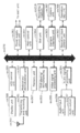
- Figure 20 illustrates how a video stream is stored in a stream of PES packets in more detail.
- the first bar in FIG. 15 shows a video frame stream in a video stream.
- the second bar shows the stream of PES packets.
- the video stream is divided into pictures as I pictures, B pictures, and P pictures each of which is a video presentation unit, and the pictures are stored in a payload of each of the PES packets.
- Each of the PES packets has a PES header, and the PES header stores a Presentation Time-Stamp (PTS) indicating a display time of the picture, and a Decoding Time-Stamp (DTS) indicating a decoding time of the picture.
- PTS Presentation Time-Stamp
- DTS Decoding Time-Stamp
- FIG 21 illustrates a format of TS packets to be finally written on the multiplexed data.
- Each of the TS packets is a 188-byte fixed length packet including a 4-byte TS header having information, such as a PID for identifying a stream and a 184-byte TS payload for storing data.
- the PES packets are divided, and stored in the TS payloads, respectively.
- each of the TS packets is given a 4-byte TP_Extra_Header, thus resulting in 192-byte source packets.
- the source packets are written on the multiplexed data.
- the TP_Extra_Header stores information such as an Arrival_Time_Stamp (ATS).
- ATS Arrival_Time_Stamp
- the ATS shows a transfer start time at which each of the TS packets is to be transferred to a PID filter.
- the source packets are arranged in the multiplexed data as shown at the bottom of FIG. 16.
- the numbers incrementing from the head of the multiplexed data are called source packet numbers (SPNs).
- Each of the TS packets included in the multiplexed data includes not only streams of audio, video, subtitles and others, but also a Program Association Table (PAT), a Program Map Table (PMT), and a Program Clock Reference (PCR).
- the PAT shows what a PID in a PMT used in the multiplexed data indicates, and a PID of the PAT itself is registered as zero.
- the PMT stores PIDs of the streams of video, audio, subtitles and others included in the multiplexed data, and attribute information of the streams corresponding to the PIDs.
- the PMT also has various descriptors relating to the multiplexed data. The descriptors have information such as copy control information showing whether copying of the multiplexed data is permitted or not.
- the PCR stores STC time information corresponding to an ATS showing when the PCR packet is transferred to a decoder, in order to achieve synchronization between an Arrival Time Clock (ATC) that is a time axis of ATSs, and an System Time Clock (STC) that is a time axis of PTSs and DTSs.
- ATC Arrival Time Clock
- STC System Time Clock
- FIG 22 illustrates the data structure of the PMT in detail.
- a PMT header is disposed at the top of the PMT.
- the PMT header describes the length of data included in the PMT and others.
- a plurality of descriptors relating to the multiplexed data is disposed after the PMT header. Information such as the copy control information is described in the descriptors.
- a plurality of pieces of stream information relating to the streams included in the multiplexed data is disposed.
- Each piece of stream information includes stream descriptors each describing information, such as a stream type for identifying a compression codec of a stream, a stream PID, and stream attribute information (such as a frame rate or an aspect ratio).
- the stream descriptors are equal in number to the number of streams in the multiplexed data.
- the multiplexed data When the multiplexed data is recorded on a recording medium and others, it is recorded together with multiplexed data information files.
- Each of the multiplexed data information files is management information of the multiplexed data as shown in FIG. 18.
- the multiplexed data information files are in one to one correspondence with the multiplexed data, and each of the files includes multiplexed data information, stream attribute information, and an entry map.
- the multiplexed data includes a system rate, a reproduction start time, and a reproduction end time.
- the system rate indicates the maximum transfer rate at which a system target decoder to be described later transfers the multiplexed data to a PID filter.
- the intervals of the ATSs included in the multiplexed data are set to not higher than a system rate.
- the reproduction start time indicates a PTS in a video frame at the head of the multiplexed data. An interval of one frame is added to a PTS in a video frame at the end of the multiplexed data, and the PTS is set to the reproduction end time.
- a piece of attribute information is registered in the stream attribute information, for each PID of each stream included in the multiplexed data.
- Each piece of attribute information has different information depending on whether the corresponding stream is a video stream, an audio stream, a presentation graphics stream, or an interactive graphics stream.
- Each piece of video stream attribute information carries information including what kind of compression codec is used for compressing the video stream, and the resolution, aspect ratio and frame rate of the pieces of picture data that is included in the video stream.
- Each piece of audio stream attribute information carries information including what kind of compression codec is used for compressing the audio stream, how many channels are included in the audio stream, which language the audio stream supports, and how high the sampling frequency is.
- the video stream attribute information and the audio stream attribute information are used for initialization of a decoder before the player plays back the information.
- the multiplexed data to be used is of a stream type included in the PMT. Furthermore, when the multiplexed data is recorded on a recording medium, the video stream attribute information included in the multiplexed data information is used. More specifically, the video coding method or the video coding apparatus described in each of Embodiments includes a step or a unit for allocating unique information indicating video data generated by the video coding method or the video coding apparatus in each of Embodiments, to the stream type included in the PMT or the video stream attribute information. With the configuration, the video data generated by the video coding method or the video coding apparatus described in each of Embodiments can be distinguished from video data that conforms to another standard.
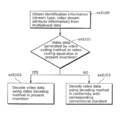
- Step exS100 the stream type included in the PMT or the video stream attribute information is obtained from the multiplexed data.
- Step exS101 it is determined whether or not the stream type or the video stream attribute information indicates that the multiplexed data is generated by the video coding method or the video coding apparatus in each of Embodiments.
- Step exS102 decoding is performed by the video decoding method in each of Embodiments.
- Step exS103 decoding is performed by a video decoding method in conformity with the conventional standards.
- FIG. 21 illustrates a configuration of the LSI ex500 that is made into one chip.
- the LSI ex500 includes elements ex501, ex502, ex503, ex504, ex505, ex506, ex507, ex508, and ex509 to be described below, and the elements are connected to each other through a bus ex510.
- the power supply circuit unit ex505 is activated by supplying each of the elements with power when the power supply circuit unit ex505 is turned on.
- the LSI ex500 receives an AV signal from a microphone ex117, a camera ex113, and others through an AV IO ex509 under control of a control unit ex501 including a CPU ex502, a memory controller ex503, a stream controller ex504, and a driving frequency control unit ex512.
- the received AV signal is temporarily stored in an external memory ex511, such as an SDRAM.
- the stored data is segmented into data portions according to the processing amount and speed to be transmitted to a signal processing unit ex507.
- the signal processing unit ex507 codes an audio signal and/or a video signal.
- the coding of the video signal is the coding described in each of Embodiments.
- the signal processing unit ex507 sometimes multiplexes the coded audio data and the coded video data, and a stream IO ex506 provides the multiplexed data outside.
- the provided multiplexed data is transmitted to the base station ex107, or written on the recording media ex215.
- the data should be temporarily stored in the buffer ex508 so that the data sets are synchronized with each other.
- the memory ex511 is an element outside the LSI ex500, it may be included in the LSI ex500.
- the buffer ex508 is not limited to one buffer, but may be composed of buffers. Furthermore, the LSI ex500 may be made into one chip or a plurality of chips.
- control unit ex510 includes the CPU ex502, the memory controller ex503, the stream controller ex504, the driving frequency control unit ex512
- the configuration of the control unit ex510 is not limited to such.
- the signal processing unit ex507 may further include a CPU. Inclusion of another CPU in the signal processing unit ex507 can improve the processing speed.
- the CPU ex502 may serve as or be a part of the signal processing unit ex507, and, for example, may include an audio signal processing unit.
- the control unit ex501 includes the signal processing unit ex507 or the CPU ex502 including a part of the signal processing unit ex507.
- LSI LSI
- IC system LSI
- super LSI ultra LSI depending on the degree of integration
- ways to achieve integration are not limited to the LSI, and a special circuit or a general purpose processor and so forth can also achieve the integration.
- Field Programmable Gate Array (FPGA) that can be programmed after manufacturing LSIs or a reconfigurable processor that allows re-configuration of the connection or configuration of an LSI can be used for the same purpose.
- Embodiment 11 When video data generated in the video coding method or by the video coding apparatus described in each of Embodiments is decoded, compared to when video data that conforms to a conventional standard, such as MPEG-2, MPEG4-AVC, and VC-1 is decoded, the processing amount probably increases. Thus, the LSI ex500 needs to be set to a driving frequency higher than that of the CPU ex502 to be used when video data in conformity with the conventional standard is decoded. However, when the driving frequency is set higher, there is a problem that the power consumption increases.
- a conventional standard such as MPEG-2, MPEG4-AVC, and VC-1
- the video decoding apparatus such as the television ex300 and the LSI ex500 is configured to determine to which standard the video data conforms, and switch between the driving frequencies according to the determined standard.
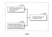
- FIG. 22 illustrates a configuration ex800 in Embodiment 11.
- a driving frequency switching unit ex803 sets a driving frequency to a higher driving frequency when video data is generated by the video coding method or the video coding apparatus described in each of Embodiments. Then, the driving frequency switching unit ex803 instructs a decoding processing unit ex801 that executes the video decoding method described in each of Embodiments to decode the video data.
- the driving frequency switching unit ex803 sets a driving frequency to a lower driving frequency than that of the video data generated by the video coding method or the video coding apparatus described in each of Embodiments. Then, the driving frequency switching unit ex803 instructs the decoding processing unit ex802 that conforms to the conventional standard to decode the video data.
- the driving frequency switching unit ex803 includes the CPU ex502 and the driving frequency control unit ex512 in FIG. 21.
- each of the decoding processing unit ex801 that executes the video decoding method described in each of Embodiments and the decoding processing unit ex802 that conforms to the conventional standard corresponds to the signal processing unit ex507 in FIG. 19.
- the CPU ex502 determines to which standard the video data conforms.
- the driving frequency control unit ex512 determines a driving frequency based on a signal from the CPU ex502.
- the signal processing unit ex507 decodes the video data based on the signal from the CPU ex502. For example, the identification information described in Embodiment 9 is probably used for identifying the video data.
- the identification information is not limited to the one described in Embodiment 9 but may be any information as long as the information indicates to which standard the video data conforms. For example, when which standard video data conforms to can be determined based on an external signal for determining that the video data is used for a television or a disk, etc., the determination may be made based on such an external signal.
- the CPU ex502 selects a driving frequency based on, for example, a look-up table in which the standards of the video data are associated with the driving frequencies as shown in FIG. 24.
- the driving frequency can be selected by storing the look-up table in the buffer ex508 and in an internal memory of an LSI, and with reference to the look-up table by the CPU ex502.
- Step exS200 the signal processing unit ex507 obtains identification information from the multiplexed data.
- Step exS201 the CPU ex502 determines whether or not the video data is generated by the coding method and the coding apparatus described in each of Embodiments, based on the identification information.
- Step exS202 the CPU ex502 transmits a signal for setting the driving frequency to a higher driving frequency to the driving frequency control unit ex512. Then, the driving frequency control unit ex512 sets the driving frequency to the higher driving frequency.
- Step exS203 when the identification information indicates that the video data conforms to the conventional standard, such as MPEG-2, MPEG4-AVC, and VC-1, in Step exS203, the CPU ex502 transmits a signal for setting the driving frequency to a lower driving frequency to the driving frequency control unit ex512. Then, the driving frequency control unit ex512 sets the driving frequency to the lower driving frequency than that in the case where the video data is generated by the video coding method and the video coding apparatus described in each of Embodiment.
- the conventional standard such as MPEG-2, MPEG4-AVC, and VC-1
- the power conservation effect can be improved by changing the voltage to be applied to the LSI ex500 or an apparatus including the LSI ex500.
- the voltage to be applied to the LSI ex500 or the apparatus including the LSI ex500 is probably set to a voltage lower than that in the case where the driving frequency is set higher.
- the driving frequency when the processing amount for decoding is larger, the driving frequency may be set higher, and when the processing amount for decoding is smaller, the driving frequency may be set lower as the method for setting the driving frequency.
- the setting method is not limited to the ones described above.
- the driving frequency is probably set in reverse order to the setting described above.
- the method for setting the driving frequency is not limited to the method for setting the driving frequency lower.
- the identification information indicates that the video data is generated by the video coding method and the video coding apparatus described in each of Embodiments, the voltage to be applied to the LSI ex500 or the apparatus including the LSI ex500 is probably set higher.
- the identification information indicates that the video data conforms to the conventional standard, such as MPEG-2, MPEG4-AVC, and VC-1
- the voltage to be applied to the LSI ex500 or the apparatus including the LSI ex500 is probably set lower.
- the driving of the CPU ex502 does not probably have to be suspended.
- the identification information indicates that the video data conforms to the conventional standard, such as MPEG-2, MPEG4-AVC, and VC-1
- the driving of the CPU ex502 is probably suspended at a given time because the CPU ex502 has extra processing capacity.
- the suspending time is probably set shorter than that in the case where when the identification information indicates that the video data conforms to the conventional standard, such as MPEG-2, MPEG4-AVC, and VC-1.
- the power conservation effect can be improved by switching between the driving frequencies in accordance with the standard to which the video data conforms. Furthermore, when the LSI ex500 or the apparatus including the LSI ex500 is driven using a battery, the battery life can be extended with the power conservation effect.
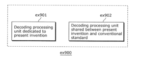
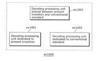
- the decoding processing unit for implementing the video decoding method described in each of Embodiments and the decoding processing unit that conforms to the conventional standard, such as MPEG-2, MPEG4-AVC, and VC-1 are partly shared.
- Ex900 in Figure 30a shows an example of the configuration.
- the video decoding method described in each of Embodiments and the video decoding method that conforms to MPEG4-AVC have, partly in common, the details of processing, such as entropy coding, inverse quantization, deblocking filtering, and motion compensated prediction.
- the details of processing to be shared probably includes use of a decoding processing unit ex902 that conforms to MPEG4-AVC.
- a dedicated decoding processing unit ex901 is probably used for other processing unique to the present invention. Since the present invention is characterized by a transformation unit in particular, for example, the dedicated decoding processing unit ex901 is used for inverse transform. Otherwise, the decoding processing unit is probably shared for one of the entropy coding, inverse quantization, deblocking filtering, and motion compensated prediction, or all of the processing.
- the decoding processing unit for implementing the video decoding method described in each of Embodiments may be shared for the processing to be shared, and a dedicated decoding processing unit may be used for processing unique to that of MPEG4-AVC.
- ex1000 in Figure 30b shows another example in that processing is partly shared.
- This example uses a configuration including a dedicated decoding processing unit ex1001 that supports the processing unique to the present invention, a dedicated decoding processing unit ex1002 that supports the processing unique to another conventional standard, and a decoding processing unit ex1003 that supports processing to be shared between the video decoding method in the present invention and the conventional video decoding method.
- the dedicated decoding processing units ex1001 and ex1002 are not necessarily specialized for the processing of the present invention and the processing of the conventional standard, respectively, and may be the ones capable of implementing general processing.
- the configuration of Embodiment 12 can be implemented by the LSI ex500.
- the present invention is applicable to a coding apparatus which codes audio, still images, and video and to a decoding apparatus which decodes data coded by the coding apparatus.
- the present invention is applicable to various audio-visual devices such as audio devices, cellular phones, digital cameras, BD recorders, and digital televisions.
Landscapes
- Engineering & Computer Science (AREA)
- Multimedia (AREA)
- Signal Processing (AREA)
- Physics & Mathematics (AREA)
- Discrete Mathematics (AREA)
- General Physics & Mathematics (AREA)
- Compression Or Coding Systems Of Tv Signals (AREA)
Abstract
Des modes de réalisation de la présente invention portent sur un système servant à recevoir et coder des images vidéo, le système comprenant : une unité de codage pour coder une tranche d'une image desdites images vidéo et/ou un ensemble de paramètres desdites images vidéo et/ou des informations d'amélioration supplémentaires desdites images vidéo, ladite étape de codage étant exécutée conformément à un procédé de codage vidéo avancé (AVC) ou un procédé de codage vidéo à haut rendement (HEVC) ; et une unité d'écriture de couche d'abstraction réseau (NAL) pour écrire un ou plusieurs paramètres dans un en-tête NAL desdites images vidéo codées et délivrer lesdites images vidéo codées ; lesdites images vidéo codées délivrées pouvant être lues et décodées soit par un décodeur vidéo AVC standard soit par un décodeur vidéo HEVC.
Applications Claiming Priority (2)
| Application Number | Priority Date | Filing Date | Title |
|---|---|---|---|
| US201161439101P | 2011-02-03 | 2011-02-03 | |
| US61/439,101 | 2011-02-03 |
Publications (1)
| Publication Number | Publication Date |
|---|---|
| WO2012105265A1 true WO2012105265A1 (fr) | 2012-08-09 |
Family
ID=46602487
Family Applications (1)
| Application Number | Title | Priority Date | Filing Date |
|---|---|---|---|
| PCT/JP2012/000708 Ceased WO2012105265A1 (fr) | 2011-02-03 | 2012-02-02 | Systèmes et procédés de codage et de décodage vidéo prenant en charge une fonctionnalité de compatibilité avec des lecteurs vidéo patrimoniaux |
Country Status (1)
| Country | Link |
|---|---|
| WO (1) | WO2012105265A1 (fr) |
Cited By (9)
| Publication number | Priority date | Publication date | Assignee | Title |
|---|---|---|---|---|
| CN103281588A (zh) * | 2013-05-15 | 2013-09-04 | 无锡北斗星通信息科技有限公司 | 使用hevc视频解码的超高清数字电视接收机 |
| WO2014166334A1 (fr) * | 2013-04-10 | 2014-10-16 | 中兴通讯股份有限公司 | Procédé, système et dispositif de codage et de décodage d'informations de profondeur |
| WO2015047162A1 (fr) * | 2013-09-26 | 2015-04-02 | Telefonaktiebolaget L M Ericsson (Publ) | Vidéo évolutive à codec hybride |
| WO2015065037A1 (fr) * | 2013-10-29 | 2015-05-07 | 엘지전자 주식회사 | Procédé et appareil d'émission et de réception de signal radiodiffusé servant à fournir un service radiodiffusé sur ip à base d'hevc |
| US9380289B2 (en) | 2012-07-20 | 2016-06-28 | Qualcomm Incorporated | Parameter sets in video coding |
| US9451256B2 (en) | 2012-07-20 | 2016-09-20 | Qualcomm Incorporated | Reusing parameter sets for video coding |
| CN103281588B (zh) * | 2013-05-15 | 2016-11-30 | 李准 | 使用hevc视频解码的超高清数字电视接收机 |
| CN108718415A (zh) * | 2013-04-17 | 2018-10-30 | 高通股份有限公司 | 多层视频译码中的交叉层图片类型对准的指示 |
| US10291922B2 (en) | 2013-10-28 | 2019-05-14 | Arris Enterprises Llc | Method and apparatus for decoding an enhanced video stream |
Citations (1)
| Publication number | Priority date | Publication date | Assignee | Title |
|---|---|---|---|---|
| WO2008130500A2 (fr) * | 2007-04-18 | 2008-10-30 | Thomson Licensing | Systèmes de codage |
-
2012
- 2012-02-02 WO PCT/JP2012/000708 patent/WO2012105265A1/fr not_active Ceased
Patent Citations (1)
| Publication number | Priority date | Publication date | Assignee | Title |
|---|---|---|---|---|
| WO2008130500A2 (fr) * | 2007-04-18 | 2008-10-30 | Thomson Licensing | Systèmes de codage |
Non-Patent Citations (3)
| Title |
|---|
| CHONGSOON LIM ET AL.: "Design consideration for compatibility with AVC NAL units", JOINT COLLABORATIVE TEAM ON VIDEO CODING (JCT-VC) OF ITU-T SG16 WP3 AND ISO/IEC JTC1/SC29/WG11, JCTVC-E375 R1, 5TH MEETING, March 2011 (2011-03-01), GENEVA, pages 1 - 2 * |
| MARTIN WINKEN ET AL.: "Description of video coding technology proposal by Fraunhofer HHI", JOINT COLLABORATIVE TEAM ON VIDEO CODING (JCT-VC) OF ITU-T SG16 WP3 AND ISO/IEC JTC1/SC29/WG11, JCTVC-A116, 1ST MEETING, April 2010 (2010-04-01), DRESDEN, DE, pages 1 - 5 * |
| YE-KUI WANG ET AL.: "On NAL unit header", JOINT COLLABORATIVE TEAM ON VIDEO CODING (JCT-VC) OF ITU-T SG16 WP3 AND ISO/IEC JTC1/SC29/WG11, JCTVC-D080, 4TH MEETING, January 2011 (2011-01-01), DAEGU, KR, pages 1 - 3 * |
Cited By (17)
| Publication number | Priority date | Publication date | Assignee | Title |
|---|---|---|---|---|
| US9380289B2 (en) | 2012-07-20 | 2016-06-28 | Qualcomm Incorporated | Parameter sets in video coding |
| US9451256B2 (en) | 2012-07-20 | 2016-09-20 | Qualcomm Incorporated | Reusing parameter sets for video coding |
| WO2014166334A1 (fr) * | 2013-04-10 | 2014-10-16 | 中兴通讯股份有限公司 | Procédé, système et dispositif de codage et de décodage d'informations de profondeur |
| CN104320644A (zh) * | 2013-04-10 | 2015-01-28 | 中兴通讯股份有限公司 | 一种深度信息的编解码方法、系统及装置 |
| US10659813B2 (en) | 2013-04-10 | 2020-05-19 | Zte Corporation | Method, system and device for coding and decoding depth information |
| CN104320644B (zh) * | 2013-04-10 | 2019-07-05 | 中兴通讯股份有限公司 | 一种深度信息的编解码方法、系统及装置 |
| CN108718415A (zh) * | 2013-04-17 | 2018-10-30 | 高通股份有限公司 | 多层视频译码中的交叉层图片类型对准的指示 |
| CN106060646A (zh) * | 2013-05-15 | 2016-10-26 | 蔡留凤 | 采用字幕处理模块的超高清数字电视接收机 |
| CN103281588A (zh) * | 2013-05-15 | 2013-09-04 | 无锡北斗星通信息科技有限公司 | 使用hevc视频解码的超高清数字电视接收机 |
| CN103281588B (zh) * | 2013-05-15 | 2016-11-30 | 李准 | 使用hevc视频解码的超高清数字电视接收机 |
| CN106060647A (zh) * | 2013-05-15 | 2016-10-26 | 蔡留凤 | 采用字幕处理模块的超高清数字电视接收机的工作方法 |
| US10257527B2 (en) | 2013-09-26 | 2019-04-09 | Telefonaktiebolaget Lm Ericsson (Publ) | Hybrid codec scalable video |
| WO2015047162A1 (fr) * | 2013-09-26 | 2015-04-02 | Telefonaktiebolaget L M Ericsson (Publ) | Vidéo évolutive à codec hybride |
| US10291922B2 (en) | 2013-10-28 | 2019-05-14 | Arris Enterprises Llc | Method and apparatus for decoding an enhanced video stream |
| KR101797504B1 (ko) * | 2013-10-29 | 2017-11-15 | 엘지전자 주식회사 | Hevc 기반의 ip 방송 서비스 제공을 위한 방송 신호 송수신 방법 및 장치 |
| US9854333B2 (en) | 2013-10-29 | 2017-12-26 | Lg Electronics Inc. | Method and apparatus for transmitting and receiving broadcast signal for providing HEVC based IP broadcast service |
| WO2015065037A1 (fr) * | 2013-10-29 | 2015-05-07 | 엘지전자 주식회사 | Procédé et appareil d'émission et de réception de signal radiodiffusé servant à fournir un service radiodiffusé sur ip à base d'hevc |
Similar Documents
| Publication | Publication Date | Title |
|---|---|---|
| KR102030205B1 (ko) | 시간 움직임 벡터 예측을 사용하여 비디오를 부호화 및 복호하는 방법 및 장치 | |
| CA2827278C (fr) | Procede de codage d'image, procede de decodage d'image, dispositif de codage d'image, dispositif de decodage d'image et dispositif de codage/decodage d'image | |
| EP2749027B1 (fr) | Procédés et appareils permettant de coder et de décoder une vidéo au moyen d'une description mise à jour de tampon | |
| WO2012160797A1 (fr) | Procédés et appareils de codage et de décodage de vidéo à l'aide d'une prédiction inter-plans colorés | |
| EP2843945B1 (fr) | Procédé de codage d'image, procédé de décodage d'image, dispositif de codage d'image, dispositif de décodage d'image et dispositif de codage/décodage d'image | |
| WO2013027407A1 (fr) | Procédés et appareils de codage, d'extraction et de décodage d'une vidéo à l'aide d'une technique de codage de pavé | |
| WO2012172779A1 (fr) | Procédé et appareil de codage décodage vidéo au moyen d'une matrice de quantification adaptative dépendant d'un mode de prédiction intra | |
| WO2012117744A1 (fr) | Procédé de codage d'une image dans une image codée, procédé de décodage d'une image codée et appareils associés | |
| CA2841107C (fr) | Codage et decodage d'image employant le codage arithmetique binaire adaptatif de contexte et un mode de derivation | |
| CA2827194A1 (fr) | Procedes de codage et de decodage d'image, dispositifs de codage et de decodage d'image et dispositif de codage/decodage d'image | |
| WO2012105265A1 (fr) | Systèmes et procédés de codage et de décodage vidéo prenant en charge une fonctionnalité de compatibilité avec des lecteurs vidéo patrimoniaux | |
| WO2012090504A1 (fr) | Procédés et appareils pour coder et décoder un flux de données vidéo | |
| AU2011306322B2 (en) | Image coding method, image decoding method, image coding apparatus, and image decoding apparatus | |
| WO2012023281A1 (fr) | Procédé de décodage d'image vidéo, procédé de codage d'image vidéo, appareil de décodage d'image vidéo, appareil de codage d'image vidéo | |
| EP2835971A1 (fr) | Procédé de codage d'image, procédé de décodage d'image, dispositif de codage d'image et dispositif de décodage d'image | |
| WO2015177966A1 (fr) | Procédé d'encodage d'image et dispositif d'encodage d'image | |
| WO2012108181A1 (fr) | Procédés et appareils pour coder et décoder une vidéo à l'aide d'images de référence multiples | |
| JP2016201839A (ja) | 複数の参照ピクチャを用いた、動画像符号化方法、動画像復号方法、動画像符号化装置、及び、動画像復号装置 | |
| CA2825900C (fr) | Procede de codage video et procede de decodage video | |
| WO2013105207A1 (fr) | Procédé de codage vidéo, appareil de codage vidéo, procédé de décodage vidéo et appareil de décodage vidéo | |
| WO2012124347A1 (fr) | Procédés et appareils pour coder et décoder une vidéo à l'aide de valeurs de type d'unité nal réservée du standard avc | |
| WO2013001796A1 (fr) | Procédés et appareils de codage vidéo à l'aide d'un mécanisme de gestion de mémoire adaptative pour des images de référence | |
| EP2876878B1 (fr) | Procédé de codage d'image, procédé de décodage d'image, dispositif de codage d'image, et dispositif de décodage d'image | |
| WO2012153538A1 (fr) | Procédés permettant de coder et de décoder des données vidéo à l'aide d'un procédé de filtrage adaptatif | |
| WO2013021601A1 (fr) | Procédés et appareils de codage et décodage de vidéo utilisant un plan de gestion de mémoire d'image de référence adaptatif pour prendre en charge une graduation temporelle |
Legal Events
| Date | Code | Title | Description |
|---|---|---|---|
| 121 | Ep: the epo has been informed by wipo that ep was designated in this application |
Ref document number: 12741959 Country of ref document: EP Kind code of ref document: A1 |
|
| NENP | Non-entry into the national phase |
Ref country code: DE |
|
| 122 | Ep: pct application non-entry in european phase |
Ref document number: 12741959 Country of ref document: EP Kind code of ref document: A1 |