WO2012105300A1 - Système de pile à combustible - Google Patents
Système de pile à combustible Download PDFInfo
- Publication number
- WO2012105300A1 WO2012105300A1 PCT/JP2012/050693 JP2012050693W WO2012105300A1 WO 2012105300 A1 WO2012105300 A1 WO 2012105300A1 JP 2012050693 W JP2012050693 W JP 2012050693W WO 2012105300 A1 WO2012105300 A1 WO 2012105300A1
- Authority
- WO
- WIPO (PCT)
- Prior art keywords
- gas
- ejector
- air
- fuel cell
- fuel
- Prior art date
- Legal status (The legal status is an assumption and is not a legal conclusion. Google has not performed a legal analysis and makes no representation as to the accuracy of the status listed.)
- Ceased
Links
Images


Classifications
-
- H—ELECTRICITY
- H01—ELECTRIC ELEMENTS
- H01M—PROCESSES OR MEANS, e.g. BATTERIES, FOR THE DIRECT CONVERSION OF CHEMICAL ENERGY INTO ELECTRICAL ENERGY
- H01M8/00—Fuel cells; Manufacture thereof
- H01M8/04—Auxiliary arrangements, e.g. for control of pressure or for circulation of fluids
- H01M8/04082—Arrangements for control of reactant parameters, e.g. pressure or concentration
- H01M8/04089—Arrangements for control of reactant parameters, e.g. pressure or concentration of gaseous reactants
- H01M8/04097—Arrangements for control of reactant parameters, e.g. pressure or concentration of gaseous reactants with recycling of the reactants
-
- H—ELECTRICITY
- H01—ELECTRIC ELEMENTS
- H01M—PROCESSES OR MEANS, e.g. BATTERIES, FOR THE DIRECT CONVERSION OF CHEMICAL ENERGY INTO ELECTRICAL ENERGY
- H01M8/00—Fuel cells; Manufacture thereof
- H01M8/06—Combination of fuel cells with means for production of reactants or for treatment of residues
- H01M8/0606—Combination of fuel cells with means for production of reactants or for treatment of residues with means for production of gaseous reactants
- H01M8/0612—Combination of fuel cells with means for production of reactants or for treatment of residues with means for production of gaseous reactants from carbon-containing material
- H01M8/0625—Combination of fuel cells with means for production of reactants or for treatment of residues with means for production of gaseous reactants from carbon-containing material in a modular combined reactor/fuel cell structure
-
- Y—GENERAL TAGGING OF NEW TECHNOLOGICAL DEVELOPMENTS; GENERAL TAGGING OF CROSS-SECTIONAL TECHNOLOGIES SPANNING OVER SEVERAL SECTIONS OF THE IPC; TECHNICAL SUBJECTS COVERED BY FORMER USPC CROSS-REFERENCE ART COLLECTIONS [XRACs] AND DIGESTS
- Y02—TECHNOLOGIES OR APPLICATIONS FOR MITIGATION OR ADAPTATION AGAINST CLIMATE CHANGE
- Y02E—REDUCTION OF GREENHOUSE GAS [GHG] EMISSIONS, RELATED TO ENERGY GENERATION, TRANSMISSION OR DISTRIBUTION
- Y02E60/00—Enabling technologies; Technologies with a potential or indirect contribution to GHG emissions mitigation
- Y02E60/30—Hydrogen technology
- Y02E60/50—Fuel cells
Definitions
- the present invention relates to a fuel cell system, and more particularly to a technique for improving the system efficiency of the fuel cell system and reducing the size of the apparatus.
- a fuel cell is a device that generates an electric power by forming an air electrode layer on one side of an electrolyte layer and a fuel electrode layer on the other side, and ions are conducted through the electrolyte layer.
- solid oxide fuel cells (SOFCs) and molten carbonate fuel cells (MCFCs) are known as types of fuel cells in which water (water vapor) is generated at the fuel electrode.
- SOFC solid oxide fuel cells
- MCFCs molten carbonate fuel cells
- Water water vapor
- carbon dioxide carbon dioxide
- electrons are generated. Then, the generated electrons flow through the external circuit, so that electric energy can be taken out.
- an anode off-gas containing steam is introduced into the reformer to perform steam reforming (Patent Document) 2).
- the circulation rate is the ratio (circulation gas amount / anode off gas amount) of the circulating gas (circulation gas) in the anode off gas.
- Patent Document 3 discloses a fuel cell system in which a gas separator is installed on the downstream side of the fuel cell.
- the gas separator separates unused hydrogen and water vapor from the anode off-gas discharged from the anode electrode of the fuel cell, and supplies the separated hydrogen and water vapor to the reformer again via the ejector.
- the ejector injects the driving gas supplied from the driving gas inlet at high speed from the nozzle, thereby generating a negative pressure around the jet and supplying the gas around the jet, specifically, the suction gas inlet. Aspirate the suction gas to be used.
- the suction gas is mixed with the driving gas, pressurized, and discharged from the outlet of the ejector.
- the ejector has a function of converting the kinetic energy of the driving gas into the static pressure of the mixed gas of the suction gas and the driving gas.
- the ratio of the mass flow rate (circulation gas flow rate) G2 of the suction gas to the mass flow rate (drive gas flow rate) G1 of the drive gas is referred to as G2 / G1 ratio.
- the magnitude of this G2 / G1 ratio is determined by the pressure increase amount of the ejector (the pressure of the suction gas supplied from the suction gas inlet (static pressure) and the pressure of the ejector exhaust gas discharged from the outlet of the ejector (static pressure)). Inversely proportional to the difference.
- the ejector sucks suction gas at a circulating gas flow rate G2 determined from a G2 / G1 ratio inversely proportional to the pressure increase amount.
- the drive gas of the ejector is a fuel gas and the suction gas is a circulating gas that is a part of the anode off gas
- the circulation rate is increased in order to improve the reforming rate in the reformer
- G2 The / G1 ratio needs to be increased.
- the G2 / G1 ratio may not be increased to a desired value because the boosting capability of the ejector is limited.
- the circulation gas may not be sufficiently boosted.
- the pressure increase amount of the ejector is increased in order to reduce the size of the reformer and the fuel cell, the circulating gas flow rate G2 is limited, and the amount of steam supplied to the reformer is insufficient.
- the catalyst may deteriorate due to a decrease in the mass ratio or carbon deposition due to a disproportionation reaction.
- the G2 / G1 ratio is reduced to increase the amount of pressurization of the ejector, and it is necessary for the reformer.
- the amount of water vapor can be supplied.
- this gas separator separates water vapor and hydrogen by the difference between the gas pressure on the inlet side and the gas pressure on the outlet side of the gas separator. Therefore, there is a large gas pressure difference before and after the separator. Necessary. Therefore, it is difficult to reduce the size of the fuel cell and the reformer, the system is enlarged, and complicated control such as pressure control for separating water vapor and hydrogen is required.
- the present invention has been made in order to solve the above-described problems.
- the object of the present invention is to increase the boosting amount of the ejector to improve the efficiency of the entire system, and to reduce the size of the fuel cell and the reformer. It is an object of the present invention to provide a fuel cell system capable of achieving the above.
- One embodiment of the present invention includes an air supply device that supplies air, a fuel gas supply device that supplies fuel gas, a reformer that generates reformed gas containing hydrogen from the fuel gas, and a reformed gas at the anode electrode A fuel cell in which air is supplied to the cathode electrode to generate electricity, and water vapor is generated in the anode electrode, and a recirculation system for circulating the anode off-gas discharged from the anode electrode of the fuel cell to the reformer, And a fuel cell system.
- the recirculation system includes an ejector, and a mixed gas obtained by mixing the air sent from the air supply device and the fuel gas sent from the fuel gas supply device is supplied to the drive gas inlet of the ejector. An anode off gas is supplied to the inlet.
- FIG. 1 is a block diagram showing the configuration of the fuel cell system according to the first embodiment of the present invention.
- FIG. 2 is a characteristic diagram showing the relationship between the circulating gas temperature, the system pressure loss, and the ejector pressure increase amount in the fuel cell system according to the first embodiment of the present invention.
- FIG. 3 is a flowchart showing a procedure of control processing of the back pressure adjustment valve in the fuel cell system according to the first embodiment of the present invention.
- FIG. 4 is a block diagram showing the configuration of the fuel cell system according to the second embodiment of the present invention.
- FIG. 5 is a characteristic diagram showing the relationship between the circulating gas temperature, the total system pressure loss, and the ejector pressure increase amount in the fuel cell system according to the second embodiment of the present invention.
- FIG. 1 is a block diagram showing the configuration of the fuel cell system according to the first embodiment of the present invention.
- FIG. 2 is a characteristic diagram showing the relationship between the circulating gas temperature, the system pressure loss, and the ejector pressure increase amount
- FIG. 6 is a flowchart showing a control processing procedure of the second air compressor and the additional air adjustment valve in the fuel cell system according to the second embodiment of the present invention.
- FIG. 7 is a block diagram showing the configuration of the fuel cell system according to the third embodiment of the present invention.
- FIG. 8 is a characteristic diagram showing the relationship between the circulating gas temperature, the total system pressure loss, and the ejector pressure increase amount in the fuel cell system according to the third embodiment of the present invention.
- FIG. 9 is a flowchart showing the procedure of the cooling air control process in the fuel cell system according to the third embodiment of the present invention.
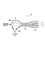
- FIG. 10 is an explanatory diagram showing the configuration of the ejector used in the fuel cell system according to the embodiment of the present invention.
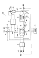
- FIG. 1 is a block diagram showing a configuration of a fuel cell system 100 according to the first embodiment of the present invention.
- the fuel cell system 100 includes a fuel cell 16 having a cathode 16a and an anode 16b, a reformer 22 that reforms hydrocarbon fuel to generate a reformed gas, and a reformer.
- fuel gas hydrogen gas, natural gas mainly composed of methane (CH 4 ), or the like can be used.
- fuel gas atomized liquid fuels such as bioethanol, gas liquefied oil (GTL), coal liquefied oil (CTL), biomass liquefied oil (BTL), etc., propane, butane, gasoline, diesel, kerosene, etc. Things can also be used.
- the reformer 22 is a heat self-supporting reformer having a heat insulating structure that does not include the reforming heater 21, and can be reacted in an autothermal reforming (ATR) mode in which air and steam are introduced.
- the reformer 22 is a heat exchanger type reformer that exchanges a part of the heat necessary for reforming from the reforming heater 21 that burns the remainder of the anode off-gas, and is an air-added steam reforming mode. Can also be reacted.
- the fuel cell system 100 uses the first air blower 12 for supplying air to the cathode electrode 16 a of the fuel cell 16 and the heat of the exhaust gas exhausted from the reforming heater 21 from the first air blower 12.
- a third heat exchanger 13 for heating the supplied air a second air compressor 14 (air supply device) for sending air, a fuel pump 15 (fuel gas supply device) for sending fuel gas, and a first heat And an exchanger 19 (temperature controller).
- the fuel cell 16 generates electric power by reacting the air supplied to the cathode electrode 16a (the air heated by the third heat exchanger 13) and the reformed gas supplied to the anode electrode 16b. Power is supplied to (not shown). Therefore, in the fuel cell 16, water (water vapor) is generated in the anode electrode 16b, and the anode off-gas discharged from the anode electrode 16b contains water vapor.
- the outlet of the anode 16b is connected to the flow path L1, and the flow path L1 is further branched into two flow paths L1a and L1b, and one of the flow paths L1a is the back pressure adjustment valve 17 (circulation amount regulator). )
- the other flow path L1b is connected to the gas supply port of the reforming heater 21 via the butterfly valve 18. Further, the outlet on the high temperature side of the first heat exchanger 19 is connected to the suction gas inlet 20 b of the ejector 20.
- Both the outlet of the second air compressor 14 and the outlet of the fuel pump 15 are connected to the low temperature side inlet of the first heat exchanger 19, and the outlet is connected to the drive gas inlet 20 a of the ejector 20. Therefore, the mixed gas in which the air supplied from the second air compressor 14 and the fuel gas supplied from the fuel pump 15 are mixed is heated by passing through the low temperature side of the first heat exchanger 19, and then The high-pressure driving gas is supplied to the driving gas inlet 20a of the ejector 20.
- the anode off gas discharged from the anode electrode 16b of the fuel cell 16 passes through the high temperature side of the first heat exchanger 19 and transfers heat to the mixed gas, and then as a circulating gas, the suction gas inlet of the ejector 20 20b. Further, the remainder of the anode off gas (anode off gas that does not become a circulating gas) is supplied to the reforming heater 21 via the flow path L1b and the butterfly valve 18.
- the ejector 20 sucks the suction gas supplied to the suction gas inlet 20b by the pressure of the drive gas supplied to the drive gas inlet 20a, and mixes the drive gas and the suction gas at a predetermined pressure increase amount.
- the mixed gas discharged from the outlet of the ejector 20 is a mixed gas of air, fuel gas, and anode off gas, and is called ejector exhaust gas.
- a mixed gas of air and fuel gas is supplied as a driving gas to the driving gas inlet 20a, and an anode off-gas (circulation gas) is supplied to the suction gas inlet 20b.
- the anode off-gas is sucked and increased by the pressure of the driving gas, and a gas (ejector exhaust gas) mixed with the anode off-gas is discharged from the ejector 20.
- the ejector exhaust gas is supplied to the reformer 22 via the flow path L2.
- the anode 16b of the fuel cell 16 the back pressure adjustment valve 17, the first heat exchanger 19, the ejector 20, the reformer 22, and the flow paths L1, L1a, L2, and the like are anode off-gas. This constitutes a recirculation system that circulates the fuel to the reformer 22.
- the air sent from the first air blower 12 is supplied to the low temperature side, and the exhaust gas of the reforming heater 21 is supplied to the high temperature side. Therefore, the air sent from the first air blower 12 is heated by the exhaust gas of the reforming heater 21 and then supplied to the cathode electrode 16 a of the fuel cell 16. The exhaust gas that has passed through the third heat exchanger 13 is then discharged to the outside.
- the reformer 22 includes a pressure sensor 23 that detects an inlet pressure (reformer pressure) Pr of the reformer 22 and a reformer temperature that measures a temperature (reformation temperature) Tr of the reformer 22.
- a sensor 24 is provided.
- the fuel cell 16 is provided with a stack temperature sensor 25 that measures the stack temperature Ts of the fuel cell 16.
- the fuel cell system 100 includes a control unit 11 that controls the first air blower 12, the second air compressor 14, the fuel pump 15, and the back pressure adjustment valve 17.
- the control part 11 transmits a control signal to the 1st air blower 12, the 2nd air compressor 14, the fuel pump 15, and the back pressure adjustment valve 17 with the method mentioned later.
- the control unit 11 is connected to the pressure sensor 23, the reformer temperature sensor 24, and the stack temperature sensor 25, and acquires detection data of each of these sensors.
- the controller 11 is based on the reformer pressure Pr measured by the pressure sensor 23, the reforming temperature Tr measured by the reformer temperature sensor 24, and the stack temperature Ts measured by the stack temperature sensor 25. Then, the circulation amount of the anode off gas is obtained. And the control part 11 controls the opening degree of the back pressure adjustment valve 17 based on the calculated
- FIG. 10 is a cross-sectional view of the ejector 20.
- the ejector 20 includes a nozzle 51 at the center, and the base end of the nozzle 51 is a drive gas inlet 20a.
- a cylindrical space region is formed on the side of the nozzle 51, and a part of this space region is opened to serve as the suction gas inlet 20b.
- the space area and the nozzle 51 have a double cylindrical structure, and a mixing section 52 and a diffuser 53 are provided on the downstream side thereof.
- the mixed gas is jetted from the nozzle 51 to become a high-speed flow, and the anode off-gas is sucked from the suction gas inlet 20b.
- the sucked anode off gas is mixed with the mixed gas of air and fuel gas, which is the driving gas, in the mixing section 52, and the flow rate is made uniform, so that the pressure is increased from before the mixing.
- the average flow velocity is further reduced and increased until reaching the end of the subsequent diffuser 53, and supplied to, for example, the reformer 22 shown in FIG.
- the stack temperature Ts of the fuel cell 16 and the system pressure loss, and the relationship between the circulating gas temperature and the pressure increase amount of the ejector will be described.
- the stack temperature Ts and the circulating gas temperature are assumed to be equal.
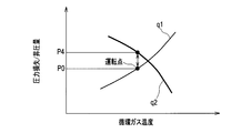
- FIG. 2 is a characteristic diagram showing the relationship between the system pressure loss and the pressure increase amount of the ejector 20 with respect to changes in the circulating gas temperature.
- a curve q1 indicates a change in the system pressure loss
- a curve q2 indicates a change in the pressure increase amount of the ejector 20.
- the system pressure loss here is the pressure loss during which the ejector exhaust gas flows from the outlet of the ejector 20 to the suction gas inlet 20b via the reformer 22, the anode 16b, and the first heat exchanger 19. From this, the pressure loss at the back pressure adjusting valve 17 is removed.
- the pressure loss including the pressure loss at the back pressure adjusting valve 17 is distinguished from the system pressure loss and is called total system pressure loss.
- the total system pressure loss refers to a pressure loss during which the ejector exhaust gas flows from the outlet of the ejector 20 to the suction gas inlet 20b via each component of the recirculation system.
- the system pressure loss increases as the stack temperature Ts increases.
- the fuel cell system 100 is operated at any point on the characteristic curve q1.
- the curve q2 indicates a desired ratio of the mass flow rate of the drive gas (hereinafter referred to as drive gas flow rate) G1 and the mass flow rate of the suction gas (hereinafter referred to as circulation gas flow rate) G2 in the ejector 20, that is, the G2 / G1 ratio.
- drive gas flow rate the mass flow rate of the drive gas
- circulation gas flow rate the mass flow rate of the suction gas
- the fuel cell system 100 is operated at an operating point where the value of the system pressure loss excluding the pressure loss at the back pressure adjustment valve 17 is P0.
- the pressure increase amount P ⁇ b> 4 in the ejector 20 is set to a flow rate required for good reforming by the reformer 22 for each flow rate of air, fuel gas, and anode off-gas circulating gas. Sometimes it is designed to be larger than the system pressure loss P0. Then, the opening degree of the back pressure adjustment valve 17 is adjusted so that the value of the total system pressure loss including the pressure loss at the back pressure adjustment valve 17 coincides with the pressure increase amount P4.
- the ejector 20 has a boosting capability to obtain a boosting amount P4 that is slightly higher than the value P0 of the system pressure loss (excluding the pressure loss at the back pressure adjusting valve 17) at the operating point.
- the mass flow rate (henceforth, air quantity) of the air sent from the 2nd air compressor 14 is adjusted so that G2 / G1 ratio may become a desired value.
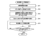
- step S ⁇ b> 11 the control unit 11 recognizes a target generated current by the fuel cell 16.
- step S12 the control unit 11 acquires the stack temperature Ts of the fuel cell 16 measured by the stack temperature sensor 25 and the reforming temperature Tr of the reformer 22 measured by the reformer temperature sensor 24.
- step S ⁇ b> 13 the control unit 11 determines the target circulating gas flow rate G ⁇ b> 2 based on the acquired information such as the target generated current and the stack temperature, and the mass flow rate of fuel gas newly supplied to the reformer 22 (hereinafter referred to as fuel).
- Gas amount) G1f and air amount G1a are determined.
- step S14 the control unit 11 calculates the target value P4 of the boost amount corresponding to the ratio (G2 / G1 ratio) between the drive gas flow rate G1 and the circulating gas flow rate G2 in the ejector 20.
- step S ⁇ b> 15 the control unit 11 transmits a control signal to the back pressure adjustment valve 17 so that the total system pressure loss including the pressure loss at the back pressure adjustment valve 17 reaches the target value P ⁇ b> 4 of the pressure increase amount of the ejector 20.
- the opening degree of the back pressure adjusting valve 17 is controlled. Thereby, the circulation amount of anode off gas is adjusted.
- the opening of the back pressure adjustment valve 17 the total system pressure loss is reduced while ensuring the flow rates of the circulating gas of the air, fuel gas, and anode off gas required by the reformer 22 and the fuel cell 16. Control is performed so as to be equal to the pressure increase amount P4 of the ejector 20.
- the fuel cell system 100 when a part of the anode off-gas is circulated and returned to the reformer 22, a mixed gas of air and fuel gas is generated and converted into the anode off-gas. It is added.
- the fuel since air is added to the drive gas of the ejector 20 in addition to the fuel gas, the fuel has a relatively large molecular weight such as gasoline, kerosene, methanol, etc., and the specific heat ratio Therefore, even when using a hydrocarbon fuel that causes a large heat loss in the flow in the ejector, the boosting capability of the ejector 20 can be reliably maintained high.
- the first heat exchanger 19 that adjusts the temperature of the anode off-gas is provided between the outlet of the anode 16b and the suction gas inlet 20b of the ejector 20. Provided. Then, at least one of air sent from the second air compressor 14 and fuel gas sent from the fuel pump 15 is supplied to the low temperature side of the first heat exchanger 19, and to the high temperature side of the first heat exchanger 19. The anode off gas is supplied. Therefore, the heat of the anode off gas can heat the air sent from the second air compressor 14 or the fuel gas sent from the fuel pump 15, so that the temperature of the circulating anode off gas can be stabilized. it can.
- the circulating gas temperature can be stabilized and the circulation rate can be stabilized. Further, when the fuel gas is supplied from a liquid or a high-pressure tank, no extra energy is required and the fuel gas can be vaporized stably.
- the back pressure adjusting valve 17 is provided, and the control unit 11 adjusts and controls the opening degree of the back pressure adjusting valve 17, thereby controlling the circulation amount of the anode off gas and the ejector.
- the amount of pressure increase at 20 is controlled to a desired value. That is, the control unit 11 adjusts and controls the opening degree of the back pressure adjustment valve 17 in accordance with the pressure increase amount of the ejector 20, so that the pressure of the gas introduced into the reformer 22 can be set to a desired pressure.
- the pressure increase amount of the ejector 20 can be improved, the fuel cell 16 and the reformer 22 can be designed with a reduced size.
- the control unit 11 adjusts and controls the opening degree of the back pressure adjustment valve 17, so that the pressure loss in the back pressure adjustment valve 17.
- the total system pressure loss including can be stabilized.
- FIG. 4 is a block diagram showing the configuration of the fuel cell system 101 according to the second embodiment.
- This fuel cell system 101 is not provided with a back pressure adjustment valve 17, and an air supply port d1 is provided in a flow path L2 connecting the outlet of the ejector 20 and the inlet of the reformer 22, and is sent from the second air compressor.
- an additional air adjustment valve 31 air supply device
- the air supply port d1 By adjusting the amount of air introduced more, the amount of air supplied to the reformer 22 can be adjusted, and the additional air adjustment valve 31 and the control unit 11 are connected by a control line. This is different from the fuel cell system 100 (FIG. 1) according to the first embodiment.
- control unit 11 includes an air amount, a fuel gas amount, an anode off-gas circulation amount, and an ejector that are supplied to the reformer 22 based on a required power generation output of the fuel cell input from the outside.
- a boost amount of 20 is obtained.
- control unit 11 adjusts the additional air based on the obtained air amount, fuel gas amount, anode off-gas circulation amount, ejector 20 pressure increase amount, and reformer pressure Pr measured by the pressure sensor 23.
- a function of controlling the amount of air supplied by the valve 31 is provided.
- the ejector 20 is designed so that the pressure increase amount matches the total system pressure loss when air and fuel gas having a flow rate smaller than the air amount required by the reformer 22 during rated operation are used as driving gas.
- the air amount G1a1 is adjusted so that the pressure increase amount of the ejector 20 matches the total system pressure loss. Since the air amount G1a1 is deficient by “G1a ⁇ G1a1” from the air amount G1a required for reforming in the reformer 22, the air amount G1a2, which is the difference, is passed through the additional air adjustment valve 31. Directly supplied to the reformer 22.
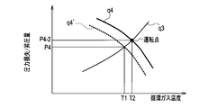
- FIG. 5 is a characteristic diagram showing the relationship between the circulating gas temperature and the total system pressure loss (curve q3) and the relationship between the circulating gas temperature and the pressure increase amount of the ejector 20 (curves q4 and q4 ').
- the fuel cell system 101 is operating at a point where the circulating gas temperature is T1 and the total system pressure loss / ejector pressure increase amount is P4.
- the stack temperature Ts of the fuel cell 16 rises and the circulating gas temperature becomes T2
- the total system pressure loss rises along the curve q3, and the required boost amount of the ejector 20 is also P4-2. To rise.
- the air amount G1a1 supplied from the second air compressor 14 is increased, and the G2 / G1 ratio is decreased.
- the characteristic curve of the pressure increase amount of the ejector 20 changes from the curve q4 ′ to the curve q4. Therefore, the pressure increase amount of the ejector 20 can be set to the value P4-2 required by the system. It becomes possible to operate at the operating point of the system pressure loss / ejector boosting amount P4-2.
- the amount of air G1a1 supplied as the drive gas for the ejector 20 increases.
- the amount of increase in the amount of air is supplied via the additional air adjustment valve 31.
- the amount of air G1a2 to be reduced is decreased. Thereby, the amount of air supplied to the reformer 22 is adjusted.
- the ejector 20 is designed so as to satisfy the required boosting performance when the air amount G1a1 smaller than the air amount G1a required by the reformer 22 is introduced into the ejector 20. Then, the air amount G1a1 supplied from the second air compressor 14 and the air amount G1a2 supplied via the additional air adjustment valve 31 are adjusted according to the change in the total system pressure loss, and supplied to the reformer 22. Control the temperature and pressure of the gas to be the desired values.
- step S ⁇ b> 31 the control unit 11 recognizes a target generated current by the fuel cell 16.
- step S32 the control unit 11 acquires the stack temperature Ts of the fuel cell 16 measured by the stack temperature sensor 25 and the reforming temperature Tr of the reformer 22 measured by the reformer temperature sensor 24.
- step S ⁇ b> 33 the control unit 11 determines the target circulating gas flow rate G ⁇ b> 2, the fuel gas amount G ⁇ b> 1 f that is newly supplied to the reformer 22, and the newly supplied air based on the acquired information such as the target generated current and stack temperature.
- the quantity G1a is determined.
- step S34 the control unit 11 calculates a target value P4 of the boost amount of the ejector 20 corresponding to the stack temperature Ts.
- step S35 the controller 11 supplies the circulating gas flow rate G2, the air amount G1a1 supplied by the second air compressor 14, and the air supplied via the additional air adjustment valve 31 to the target value P4 obtained in step S34.
- step S36 the controller 11 adjusts the second air compressor 14 so that the amount of air supplied from the second air compressor 14 becomes the air amount G1a1 determined in step S35. Further, the opening degree of the additional air adjustment valve 31 is adjusted so that the amount of air supplied from the additional air adjustment valve 31 becomes the air amount G1a2 determined in step S35.
- an air supply port d1 is provided in the flow path L2 connecting the outlet of the ejector 20 and the inlet of the reformer 22, and additional air adjustment is performed in the air supply port d1.
- air is introduced into the reformer 22 separately from the operating state of the ejector 20. Therefore, even if temperature fluctuations or gas flow rate fluctuations of the fuel cell 16 or the reformer 22 occur during operation, the circulation rate of the anode off gas can be stabilized.
- the control unit 11 determines whether the ejector exhaust gas discharged from the ejector 20 is circulated to the suction gas inlet 20b of the ejector 20 according to the pressure loss. Since the additional air adjustment valve 31 is adjusted, the composition of the gas introduced into the reformer 22 can be set to an optimum composition. Thereby, carbon deposition deterioration of the reformer 22 can be suppressed.
- the power of the second air compressor 14 can be minimized, and the reformer 22 is required even when the required power generation output in the fuel cell 16 changes.
- the gas composition to be can be stably supplied.
- FIG. 7 is a block diagram showing the configuration of the fuel cell system 102 according to the third embodiment.
- the fuel cell system 102 does not include the back pressure adjustment valve 17, and the second heat exchanger 41 is provided in the flow path L1a between the high temperature side outlet of the first heat exchanger 19 and the suction gas inlet 20b of the ejector 20.
- (Temperature regulator) provided, third air blower 42 (cooling gas supplier, temperature regulator) for supplying cooling air to the low temperature side of the second heat exchanger 41, and third It differs from the fuel cell system 100 (FIG. 1) according to the first embodiment described above in that the air blower 42 and the control unit 11 are connected by a control line.
- control unit 11 is configured such that the amount of air supplied to the reformer 22, the amount of fuel gas, the circulation amount of anode off gas, and the ejector based on the required power generation output of the fuel cell input from the outside. A boost amount of 20 is obtained. Then, the control unit 11 controls the ejector 20 based on the obtained air amount, fuel gas amount, anode off-gas circulation amount, the pressure increase amount of the ejector 20, and the reformer pressure Pr measured by the pressure sensor 23. The temperature of the supplied anode off gas is determined. Furthermore, the control part 11 controls the 3rd air blower 42 according to the calculated
- control unit 11 controls the amount of air supplied by the third air blower 42 to be supplied to the ejector 20. It is possible to adjust the temperature of the anode off gas.
- the value P4 of the total system pressure loss (mainly pressure loss in the pipes constituting the reformer 22, the fuel cell 16, and the flow paths L1, L1a, and L2) corresponding to the stack temperature Ts during rated operation is calculated.
- the circulating gas flow rate G2 and the driving gas flow rate G1 required for power generation and reforming are used. And calculate.
- the temperature of the anode off gas immediately before being sucked into the ejector 20 depends on the heat insulating performance of a pipe or the like that becomes a flow path from the outlet of the anode electrode 16b of the fuel cell 16 to the suction gas inlet 20b of the ejector 20. It can be set as a temperature proportional to the stack temperature Ts.
- the ejector 20 is designed so that the pressure increase amount of the ejector 20 matches the total system pressure loss P4 during the rated operation when the temperature of the anode off gas immediately before being sucked into the ejector 20 reaches the temperature T3 during the rated operation. To do.
- FIG. 8 is a characteristic diagram showing changes in the total system pressure loss with respect to changes in the circulating gas temperature (curve q5), and changes in the ejector pressure increase amount with respect to changes in the circulating gas temperature (curves q6, q6 ').
- curve q5 changes in the total system pressure loss with respect to changes in the circulating gas temperature
- curves q6, q6 ' changes in the ejector pressure increase amount with respect to changes in the circulating gas temperature
- the pressure increase amount of the ejector 20 can be maintained with the same G2 / G1 ratio. Can be changed.
- the pressure increase amount of the ejector 20 becomes the value P4 during rated operation by adjusting the flow rate of the cooling gas delivered from the third air blower 42 and cooling the circulating gas under the control of the control unit 11. To control.
- step S51 the control unit 11 recognizes a target generated current by the fuel cell 16.
- step S52 the control unit 11 acquires the stack temperature Ts of the fuel cell 16 measured by the stack temperature sensor 25 and the reforming temperature Tr of the reformer 22 measured by the reformer temperature sensor 24.
- step S ⁇ b> 53 the control unit 11 determines the target circulating gas flow rate G ⁇ b> 2, the fuel gas amount G ⁇ b> 1 f to be newly supplied to the reformer 22, and the newly supplied air based on the acquired information such as the target generated current and the stack temperature.
- the quantity G1a is determined.
- step S54 the control unit 11 calculates a target value P4 of the boost amount corresponding to the stack temperature Ts and the reforming temperature Tr.
- step S55 the control unit 11 realizes the target value P4 of the boosted amount obtained in step S54, and the circulating gas flow rate G2 and the driving gas flow rate G1 (the sum of the fuel gas amount G1f and the air amount G1a) obtained in step S53.
- a temperature T3 of the anode off gas for performing the calculation is calculated.
- step S56 the control unit 11 adjusts the amount of cooling air sent from the third air blower 42 so that the temperature of the anode off gas becomes the temperature T3 calculated in step S55.
- the second heat exchanger 41 that adjusts the temperature of the anode off-gas is provided between the outlet of the anode 16b and the suction gas inlet 20b of the ejector 20. Yes.
- the cooling air sent from the third air blower 42 is supplied to the low temperature side of the second heat exchanger 41, and the anode off gas is supplied to the high temperature side of the second heat exchanger 41.
- the amount of pressure increase of the ejector 20 can be changed with the same G2 / G1 ratio. .
- the control unit 11 controls the third air blower 42 according to the pressure loss while the ejector exhaust gas discharged from the ejector 20 circulates to the suction gas inlet 20 b of the ejector 20.
- the flow rate of the cooling gas sent out is adjusted, the temperature of the circulating gas is adjusted, and the pressure increase amount of the ejector 20 is controlled to a desired value. Therefore, even when the temperature of the circulating gas changes, the pressure increase amount of the ejector 20 can be maintained at a desired value, and the circulation amount of the anode off gas can be stabilized. As a result, the reforming reaction of the reformer 22, and thus the power generation behavior of the stack can be stabilized.
- the air supply port d1 and the additional air adjustment valve 31 of the second embodiment may be employed in the fuel cell system 100 of the first embodiment, and the fuel cell system 101 of the second embodiment may be employed in the third embodiment.
- the second heat exchanger 41 and the third air blower 42 may be employed.
- the back pressure regulating valve 17 of the first embodiment may be adopted for the fuel cell system 102 of the third embodiment, and all the components of the first to third embodiments can be applied in combination. is there.
- the second air compressor 14 is connected to the drive gas inlet 20a of the ejector 20 via the first heat exchanger 19, but the first heat exchanger 19 It may be directly connected to the drive gas inlet 20a of the ejector 20 without going through. That is, the outlet of the second air compressor 14 is connected to a flow path between the outlet of the first heat exchanger 19 and the driving gas inlet 20a of the ejector 20 instead of the low temperature side inlet of the first heat exchanger 19. May be.
- the drive gas flow rate G1 can be increased, and the G2 / G1 ratio of the ejector can be reduced.
- the carbon deposition deterioration of the reformer and the reduction in the reforming rate can be suppressed, the ejector pressure increase can be increased to improve the overall system efficiency, and the fuel cell and reformer can be made smaller.
Landscapes
- Life Sciences & Earth Sciences (AREA)
- Sustainable Development (AREA)
- Engineering & Computer Science (AREA)
- Manufacturing & Machinery (AREA)
- Sustainable Energy (AREA)
- Chemical & Material Sciences (AREA)
- Chemical Kinetics & Catalysis (AREA)
- Electrochemistry (AREA)
- General Chemical & Material Sciences (AREA)
- Fuel Cell (AREA)
Abstract
L'invention concerne un système de pile à combustible (100, 101, 102) comprenant : un dispositif d'alimentation en air (14) qui fournit de l'air ; un dispositif d'alimentation en gaz combustible (15) qui fournit du gaz combustible ; un reformeur (22) qui produit, à partir du gaz combustible, un gaz reformé contenant de l'hydrogène ; une pile à combustible (16) dans laquelle une anode (16b) et une cathode (16a) sont respectivement alimentées par le gaz reformé et l'air, de façon à générer de l'énergie et à entraîner l'apparition de vapeur d'eau sur l'anode (16b) ; et un système de recirculation qui fait circuler un gaz d'échappement d'anode déchargé à partir de l'anode (16b) de la pile à combustible (16) dans le reformeur (22). Le système de recirculation comprend un éjecteur (20), dans lequel une entrée de gaz d'entraînement (20a) de l'éjecteur (20) est alimentée par un gaz mélangé avec de l'air délivré par le dispositif d'alimentation en air (14) et un gaz combustible délivré par le dispositif d'alimentation en gaz combustible (15), et une entrée de gaz d'aspiration (20b) alimentée par un gaz d'échappement d'anode.
Applications Claiming Priority (2)
| Application Number | Priority Date | Filing Date | Title |
|---|---|---|---|
| JP2011-019599 | 2011-02-01 | ||
| JP2011019599A JP2012160361A (ja) | 2011-02-01 | 2011-02-01 | 燃料電池システム |
Publications (1)
| Publication Number | Publication Date |
|---|---|
| WO2012105300A1 true WO2012105300A1 (fr) | 2012-08-09 |
Family
ID=46602521
Family Applications (1)
| Application Number | Title | Priority Date | Filing Date |
|---|---|---|---|
| PCT/JP2012/050693 Ceased WO2012105300A1 (fr) | 2011-02-01 | 2012-01-16 | Système de pile à combustible |
Country Status (2)
| Country | Link |
|---|---|
| JP (1) | JP2012160361A (fr) |
| WO (1) | WO2012105300A1 (fr) |
Cited By (6)
| Publication number | Priority date | Publication date | Assignee | Title |
|---|---|---|---|---|
| WO2013045044A1 (fr) * | 2011-10-01 | 2013-04-04 | Daimler Ag | Circuit d'anode et procédé de préparation d'un redémarrage |
| WO2015040270A1 (fr) * | 2013-09-23 | 2015-03-26 | Convion Oy | Agencement de recirculation et procédé pour un système de piles à haute température |
| AT521902A1 (de) * | 2018-11-21 | 2020-06-15 | Avl List Gmbh | Brennstoffzellensystem und Verfahren zur Rezirkulation von Brennstoffabgas in einem Brennstoffzellensystem |
| AT523210A1 (de) * | 2019-12-09 | 2021-06-15 | Avl List Gmbh | Brennstoffzellensystem |
| CN113632268A (zh) * | 2019-04-26 | 2021-11-09 | Avl李斯特有限公司 | 燃料电池系统、燃料电池系统运行方法和燃料电池运输工具 |
| CN117936853A (zh) * | 2023-12-15 | 2024-04-26 | 中国石油大学(华东) | 一种带外重整的sofc发电系统 |
Families Citing this family (9)
| Publication number | Priority date | Publication date | Assignee | Title |
|---|---|---|---|---|
| EP3012894B1 (fr) * | 2013-06-17 | 2019-08-28 | Hitachi Zosen Corporation | Procédé d'économie d'énergie dans un système combiné possédant un dispositif de fabrication de bioéthanol et une pile à combustible à oxyde solide combinés en son sein |
| JP6172386B2 (ja) * | 2014-05-09 | 2017-08-02 | 日産自動車株式会社 | 燃料電池システム及び燃料電池システムの制御方法 |
| JP6455383B2 (ja) * | 2014-10-01 | 2019-01-23 | 株式会社デンソー | 燃料電池装置 |
| JP6590271B2 (ja) * | 2015-02-09 | 2019-10-16 | パナソニックIpマネジメント株式会社 | 燃料電池システム |
| JP6439545B2 (ja) * | 2015-03-31 | 2018-12-19 | 株式会社デンソー | 燃料電池システム |
| JP6598367B2 (ja) * | 2015-11-12 | 2019-10-30 | 国立研究開発法人産業技術総合研究所 | 固体酸化物形燃料電池システム及びその運転方法 |
| JP6719915B2 (ja) * | 2016-02-08 | 2020-07-08 | 三菱日立パワーシステムズ株式会社 | 燃料電池−水素製造システムおよびその運転方法 |
| JP6787037B2 (ja) * | 2016-10-24 | 2020-11-18 | 株式会社デンソー | 燃料電池システム |
| JP6981089B2 (ja) * | 2017-08-09 | 2021-12-15 | 日産自動車株式会社 | 燃料電池システム及び燃料電池システムの制御方法 |
Citations (3)
| Publication number | Priority date | Publication date | Assignee | Title |
|---|---|---|---|---|
| JP2003109628A (ja) * | 2001-09-27 | 2003-04-11 | Toto Ltd | 燃料電池システム |
| JP2003288920A (ja) * | 2002-03-27 | 2003-10-10 | Toto Ltd | 燃料電池システム |
| JP2004199997A (ja) * | 2002-12-18 | 2004-07-15 | Mitsubishi Heavy Ind Ltd | 固体酸化物形燃料電池を用いた水素利用システム |
-
2011
- 2011-02-01 JP JP2011019599A patent/JP2012160361A/ja active Pending
-
2012
- 2012-01-16 WO PCT/JP2012/050693 patent/WO2012105300A1/fr not_active Ceased
Patent Citations (3)
| Publication number | Priority date | Publication date | Assignee | Title |
|---|---|---|---|---|
| JP2003109628A (ja) * | 2001-09-27 | 2003-04-11 | Toto Ltd | 燃料電池システム |
| JP2003288920A (ja) * | 2002-03-27 | 2003-10-10 | Toto Ltd | 燃料電池システム |
| JP2004199997A (ja) * | 2002-12-18 | 2004-07-15 | Mitsubishi Heavy Ind Ltd | 固体酸化物形燃料電池を用いた水素利用システム |
Cited By (14)
| Publication number | Priority date | Publication date | Assignee | Title |
|---|---|---|---|---|
| WO2013045044A1 (fr) * | 2011-10-01 | 2013-04-04 | Daimler Ag | Circuit d'anode et procédé de préparation d'un redémarrage |
| WO2015040270A1 (fr) * | 2013-09-23 | 2015-03-26 | Convion Oy | Agencement de recirculation et procédé pour un système de piles à haute température |
| CN105580178A (zh) * | 2013-09-23 | 2016-05-11 | 康维恩公司 | 用于高温电池系统的再循环设备及方法 |
| US10511035B2 (en) | 2013-09-23 | 2019-12-17 | Convion Oy | Recirculation arrangement and method for a high temperature cell system |
| AT521902A1 (de) * | 2018-11-21 | 2020-06-15 | Avl List Gmbh | Brennstoffzellensystem und Verfahren zur Rezirkulation von Brennstoffabgas in einem Brennstoffzellensystem |
| CN113632268A (zh) * | 2019-04-26 | 2021-11-09 | Avl李斯特有限公司 | 燃料电池系统、燃料电池系统运行方法和燃料电池运输工具 |
| CN113632268B (zh) * | 2019-04-26 | 2024-06-28 | Avl李斯特有限公司 | 燃料电池系统和燃料电池系统运行方法 |
| WO2021113888A1 (fr) * | 2019-12-09 | 2021-06-17 | Avl List Gmbh | Système de pile à combustible |
| AT523210B1 (de) * | 2019-12-09 | 2021-08-15 | Avl List Gmbh | Brennstoffzellensystem |
| CN114641879A (zh) * | 2019-12-09 | 2022-06-17 | Avl李斯特有限公司 | 燃料电池系统 |
| CN114641879B (zh) * | 2019-12-09 | 2024-06-18 | Avl李斯特有限公司 | 燃料电池系统 |
| AT523210A1 (de) * | 2019-12-09 | 2021-06-15 | Avl List Gmbh | Brennstoffzellensystem |
| US12308488B2 (en) | 2019-12-09 | 2025-05-20 | Avl List Gmbh | Fuel cell system |
| CN117936853A (zh) * | 2023-12-15 | 2024-04-26 | 中国石油大学(华东) | 一种带外重整的sofc发电系统 |
Also Published As
| Publication number | Publication date |
|---|---|
| JP2012160361A (ja) | 2012-08-23 |
Similar Documents
| Publication | Publication Date | Title |
|---|---|---|
| WO2012105300A1 (fr) | Système de pile à combustible | |
| CN105580178B (zh) | 用于高温电池系统的再循环设备及方法 | |
| US10938046B2 (en) | Fuel cell system | |
| EP2697854B1 (fr) | Module de pile à combustible | |
| JP2013138017A (ja) | 燃料電池システム | |
| US20140051000A1 (en) | Fuel cell system | |
| US8808936B2 (en) | Fuel cell system and method for controlling electric current of same | |
| CN115398683A (zh) | 燃料电池系统 | |
| US8642221B2 (en) | Solid oxide fuel cell device | |
| US8546029B2 (en) | Solid oxide fuel cell | |
| CN101673835A (zh) | 燃料电池系统及其燃料供给方法 | |
| US9318756B2 (en) | Fuel cell module | |
| JP2008248851A (ja) | ポンプ装置の流量制御方法及び装置 | |
| KR101128923B1 (ko) | 재순환라인을 가지는 연료전지시스템 | |
| EP2203950A1 (fr) | Procédé de fonctionnement lors de la réduction de charge du système de pile à combustible | |
| US20090068510A1 (en) | Fuel cell system and method of operating the fuel cell system | |
| KR100987175B1 (ko) | 연료전지 시스템 및 그 연료 공급 방법 | |
| JP2008084822A (ja) | 燃料電池装置 | |
| US20080131743A1 (en) | Fuel Cell System and Associated Control Method | |
| JP7722242B2 (ja) | 燃料電池システム | |
| US9190684B2 (en) | Fuel cell module | |
| JP2007026998A (ja) | 溶融炭酸塩型燃料電池発電装置の燃料電池温度制御方法及び装置 | |
| EP2055670A2 (fr) | Dispositif de reformage de combustible et système de pile à combustible | |
| JP5248067B2 (ja) | 燃料電池システム | |
| CN120878908A (zh) | 利用尾气循环重整燃料的燃料电池系统及运行方法 |
Legal Events
| Date | Code | Title | Description |
|---|---|---|---|
| 121 | Ep: the epo has been informed by wipo that ep was designated in this application |
Ref document number: 12742000 Country of ref document: EP Kind code of ref document: A1 |
|
| NENP | Non-entry into the national phase |
Ref country code: DE |
|
| 122 | Ep: pct application non-entry in european phase |
Ref document number: 12742000 Country of ref document: EP Kind code of ref document: A1 |