WO2012105332A1 - 使い捨てのパンツ型おむつおよびその製造方法 - Google Patents
使い捨てのパンツ型おむつおよびその製造方法 Download PDFInfo
- Publication number
- WO2012105332A1 WO2012105332A1 PCT/JP2012/051153 JP2012051153W WO2012105332A1 WO 2012105332 A1 WO2012105332 A1 WO 2012105332A1 JP 2012051153 W JP2012051153 W JP 2012051153W WO 2012105332 A1 WO2012105332 A1 WO 2012105332A1
- Authority
- WO
- WIPO (PCT)
- Prior art keywords
- region
- web
- elastically
- layer sheet
- diaper
- Prior art date
- Legal status (The legal status is an assumption and is not a legal conclusion. Google has not performed a legal analysis and makes no representation as to the accuracy of the status listed.)
- Ceased
Links
Images


Classifications
-
- A—HUMAN NECESSITIES
- A61—MEDICAL OR VETERINARY SCIENCE; HYGIENE
- A61F—FILTERS IMPLANTABLE INTO BLOOD VESSELS; PROSTHESES; DEVICES PROVIDING PATENCY TO, OR PREVENTING COLLAPSING OF, TUBULAR STRUCTURES OF THE BODY, e.g. STENTS; ORTHOPAEDIC, NURSING OR CONTRACEPTIVE DEVICES; FOMENTATION; TREATMENT OR PROTECTION OF EYES OR EARS; BANDAGES, DRESSINGS OR ABSORBENT PADS; FIRST-AID KITS
- A61F13/00—Bandages or dressings; Absorbent pads
- A61F13/15—Absorbent pads, e.g. sanitary towels, swabs or tampons for external or internal application to the body; Supporting or fastening means therefor; Tampon applicators
- A61F13/45—Absorbent pads, e.g. sanitary towels, swabs or tampons for external or internal application to the body; Supporting or fastening means therefor; Tampon applicators characterised by the shape
- A61F13/49—Absorbent pads, e.g. sanitary towels, swabs or tampons for external or internal application to the body; Supporting or fastening means therefor; Tampon applicators characterised by the shape specially adapted to be worn around the waist, e.g. diapers, nappies
- A61F13/49007—Form-fitting, self-adjusting disposable diapers
- A61F13/49009—Form-fitting, self-adjusting disposable diapers with elastic means
- A61F13/49019—Form-fitting, self-adjusting disposable diapers with elastic means the elastic means being placed longitudinally, transversely or diagonally over the article
-
- A—HUMAN NECESSITIES
- A61—MEDICAL OR VETERINARY SCIENCE; HYGIENE
- A61F—FILTERS IMPLANTABLE INTO BLOOD VESSELS; PROSTHESES; DEVICES PROVIDING PATENCY TO, OR PREVENTING COLLAPSING OF, TUBULAR STRUCTURES OF THE BODY, e.g. STENTS; ORTHOPAEDIC, NURSING OR CONTRACEPTIVE DEVICES; FOMENTATION; TREATMENT OR PROTECTION OF EYES OR EARS; BANDAGES, DRESSINGS OR ABSORBENT PADS; FIRST-AID KITS
- A61F13/00—Bandages or dressings; Absorbent pads
- A61F13/15—Absorbent pads, e.g. sanitary towels, swabs or tampons for external or internal application to the body; Supporting or fastening means therefor; Tampon applicators
- A61F13/15577—Apparatus or processes for manufacturing
- A61F13/15585—Apparatus or processes for manufacturing of babies' napkins, e.g. diapers
- A61F13/15593—Apparatus or processes for manufacturing of babies' napkins, e.g. diapers having elastic ribbons fixed thereto; Devices for applying the ribbons
-
- A—HUMAN NECESSITIES
- A61—MEDICAL OR VETERINARY SCIENCE; HYGIENE
- A61F—FILTERS IMPLANTABLE INTO BLOOD VESSELS; PROSTHESES; DEVICES PROVIDING PATENCY TO, OR PREVENTING COLLAPSING OF, TUBULAR STRUCTURES OF THE BODY, e.g. STENTS; ORTHOPAEDIC, NURSING OR CONTRACEPTIVE DEVICES; FOMENTATION; TREATMENT OR PROTECTION OF EYES OR EARS; BANDAGES, DRESSINGS OR ABSORBENT PADS; FIRST-AID KITS
- A61F13/00—Bandages or dressings; Absorbent pads
- A61F13/15—Absorbent pads, e.g. sanitary towels, swabs or tampons for external or internal application to the body; Supporting or fastening means therefor; Tampon applicators
- A61F13/15577—Apparatus or processes for manufacturing
- A61F13/15699—Forming webs by bringing together several webs, e.g. by laminating or folding several webs, with or without additional treatment of the webs
-
- A—HUMAN NECESSITIES
- A61—MEDICAL OR VETERINARY SCIENCE; HYGIENE
- A61F—FILTERS IMPLANTABLE INTO BLOOD VESSELS; PROSTHESES; DEVICES PROVIDING PATENCY TO, OR PREVENTING COLLAPSING OF, TUBULAR STRUCTURES OF THE BODY, e.g. STENTS; ORTHOPAEDIC, NURSING OR CONTRACEPTIVE DEVICES; FOMENTATION; TREATMENT OR PROTECTION OF EYES OR EARS; BANDAGES, DRESSINGS OR ABSORBENT PADS; FIRST-AID KITS
- A61F13/00—Bandages or dressings; Absorbent pads
- A61F13/15—Absorbent pads, e.g. sanitary towels, swabs or tampons for external or internal application to the body; Supporting or fastening means therefor; Tampon applicators
- A61F13/42—Absorbent pads, e.g. sanitary towels, swabs or tampons for external or internal application to the body; Supporting or fastening means therefor; Tampon applicators with wetness indicator or alarm
-
- A—HUMAN NECESSITIES
- A61—MEDICAL OR VETERINARY SCIENCE; HYGIENE
- A61F—FILTERS IMPLANTABLE INTO BLOOD VESSELS; PROSTHESES; DEVICES PROVIDING PATENCY TO, OR PREVENTING COLLAPSING OF, TUBULAR STRUCTURES OF THE BODY, e.g. STENTS; ORTHOPAEDIC, NURSING OR CONTRACEPTIVE DEVICES; FOMENTATION; TREATMENT OR PROTECTION OF EYES OR EARS; BANDAGES, DRESSINGS OR ABSORBENT PADS; FIRST-AID KITS
- A61F13/00—Bandages or dressings; Absorbent pads
- A61F13/15—Absorbent pads, e.g. sanitary towels, swabs or tampons for external or internal application to the body; Supporting or fastening means therefor; Tampon applicators
- A61F13/45—Absorbent pads, e.g. sanitary towels, swabs or tampons for external or internal application to the body; Supporting or fastening means therefor; Tampon applicators characterised by the shape
- A61F13/49—Absorbent pads, e.g. sanitary towels, swabs or tampons for external or internal application to the body; Supporting or fastening means therefor; Tampon applicators characterised by the shape specially adapted to be worn around the waist, e.g. diapers, nappies
- A61F13/49007—Form-fitting, self-adjusting disposable diapers
- A61F13/49009—Form-fitting, self-adjusting disposable diapers with elastic means
- A61F13/4902—Form-fitting, self-adjusting disposable diapers with elastic means characterised by the elastic material
-
- A—HUMAN NECESSITIES
- A61—MEDICAL OR VETERINARY SCIENCE; HYGIENE
- A61F—FILTERS IMPLANTABLE INTO BLOOD VESSELS; PROSTHESES; DEVICES PROVIDING PATENCY TO, OR PREVENTING COLLAPSING OF, TUBULAR STRUCTURES OF THE BODY, e.g. STENTS; ORTHOPAEDIC, NURSING OR CONTRACEPTIVE DEVICES; FOMENTATION; TREATMENT OR PROTECTION OF EYES OR EARS; BANDAGES, DRESSINGS OR ABSORBENT PADS; FIRST-AID KITS
- A61F13/00—Bandages or dressings; Absorbent pads
- A61F13/15—Absorbent pads, e.g. sanitary towels, swabs or tampons for external or internal application to the body; Supporting or fastening means therefor; Tampon applicators
- A61F13/45—Absorbent pads, e.g. sanitary towels, swabs or tampons for external or internal application to the body; Supporting or fastening means therefor; Tampon applicators characterised by the shape
- A61F13/49—Absorbent pads, e.g. sanitary towels, swabs or tampons for external or internal application to the body; Supporting or fastening means therefor; Tampon applicators characterised by the shape specially adapted to be worn around the waist, e.g. diapers, nappies
- A61F13/49058—Absorbent pads, e.g. sanitary towels, swabs or tampons for external or internal application to the body; Supporting or fastening means therefor; Tampon applicators characterised by the shape specially adapted to be worn around the waist, e.g. diapers, nappies characterised by the modular concept of constructing the diaper
-
- A—HUMAN NECESSITIES
- A61—MEDICAL OR VETERINARY SCIENCE; HYGIENE
- A61F—FILTERS IMPLANTABLE INTO BLOOD VESSELS; PROSTHESES; DEVICES PROVIDING PATENCY TO, OR PREVENTING COLLAPSING OF, TUBULAR STRUCTURES OF THE BODY, e.g. STENTS; ORTHOPAEDIC, NURSING OR CONTRACEPTIVE DEVICES; FOMENTATION; TREATMENT OR PROTECTION OF EYES OR EARS; BANDAGES, DRESSINGS OR ABSORBENT PADS; FIRST-AID KITS
- A61F13/00—Bandages or dressings; Absorbent pads
- A61F13/15—Absorbent pads, e.g. sanitary towels, swabs or tampons for external or internal application to the body; Supporting or fastening means therefor; Tampon applicators
- A61F13/45—Absorbent pads, e.g. sanitary towels, swabs or tampons for external or internal application to the body; Supporting or fastening means therefor; Tampon applicators characterised by the shape
- A61F13/49—Absorbent pads, e.g. sanitary towels, swabs or tampons for external or internal application to the body; Supporting or fastening means therefor; Tampon applicators characterised by the shape specially adapted to be worn around the waist, e.g. diapers, nappies
- A61F13/494—Absorbent pads, e.g. sanitary towels, swabs or tampons for external or internal application to the body; Supporting or fastening means therefor; Tampon applicators characterised by the shape specially adapted to be worn around the waist, e.g. diapers, nappies characterised by edge leakage prevention means
- A61F13/49406—Absorbent pads, e.g. sanitary towels, swabs or tampons for external or internal application to the body; Supporting or fastening means therefor; Tampon applicators characterised by the shape specially adapted to be worn around the waist, e.g. diapers, nappies characterised by edge leakage prevention means the edge leakage prevention means being at the crotch region
- A61F13/49413—Absorbent pads, e.g. sanitary towels, swabs or tampons for external or internal application to the body; Supporting or fastening means therefor; Tampon applicators characterised by the shape specially adapted to be worn around the waist, e.g. diapers, nappies characterised by edge leakage prevention means the edge leakage prevention means being at the crotch region the edge leakage prevention means being an upstanding barrier
Definitions
- the present invention relates to a disposable pants-type diaper and a method for manufacturing the same.
- a disposable pant-type diaper in which at least one of the front and rear waist areas has elastic stretchability in the waist direction is known. Further, in the waist area, the elastic member in which the side part located on both sides of the body fluid absorption structure is in an extended state without including the elastic member in the extended state in the central part overlapping with the body fluid absorption structure.
- a disposable diaper in which a gather is not formed in the central part but a gather is formed in a side part is also known.
- Patent Document 1 an example of an absorbent article described in Japanese Patent Application Laid-Open No. 2001-145666 (Patent Document 1) is a disposable pant-type diaper, and an elastic stretchable part is provided in a region where a waist elastic member does not exist. In the site where the absorbent is present and is fixed in an elongated state so as to exhibit the property, it is cut without being fixed, the elastic stretchability is not substantially exhibited, and no gathers are formed.
- the waist circumference elastic member is sandwiched between two outer layer sheets.
- part which an absorber does not exist is being fixed.
- the waist circumference elastic member at the site where the absorber exists is cut and fixed by heat treatment and pressure treatment.
- the waist circumference elastic member in the absorbent article disclosed in Patent Document 1 is not fixed to other members in the portion where the absorber exists, and both the elastic member fixing sheet and the auxiliary sheet sandwiching the waist circumference elastic member are cut. ing. For this reason, it cannot be avoided that these two sheets are formed with large openings extending in a direction intersecting with all the waist elastic members.
- a concealment sheet for concealing the disordered cut end of the opening and the waist circumference elastic member is required.
- Patent Document 2 cannot be applied to a wide belt-like waist elastic member.
- This invention for solving the above-mentioned problems includes a first invention related to a disposable pants-type diaper and a second invention related to a manufacturing method thereof.
- the first invention has a transverse direction perpendicular to the longitudinal direction, a front waistline region, a rear waistline region, a crotch region, a body fluid absorbing chassis extending from the crotch region to the front and back waistline regions, In at least one waist area of the front and rear waist areas, elastically between a lateral elastic area that can elastically extend laterally on both sides of the body fluid-absorbing chassis and between the lateral elastic areas. It is a disposable pants-type diaper including a central inelastic region that does not stretch either inelastic or inelastic.
- the at least one waist region includes an outer layer sheet that does not elastically extend in the lateral direction, and an inner layer sheet that is elastically extendable in the lateral direction and is positioned on the inner surface side of the outer layer sheet.
- the inner layer sheet is joined to the inner surface of the outer layer sheet in an elongated state, and in the central inelastic region, the inner layer sheet is divided into two in the lateral direction so as to be in the side elastic region. It is in an elastically relaxed state in adjacent areas.
- the central inelastic region is formed outside the body fluid-absorbing chassis.
- the body fluid-absorbing chassis has side edges on both sides of a center line that bisects the lateral dimension of the diaper, and the side edges are elastic in the side. It is joined to the area.
- the body fluid-absorbing chassis has a barrier sheet, and the central inelastic region is joined to the body fluid-absorbing chassis from the outside of the barrier sheet.
- an indicator for notifying that urine has been excreted in the diaper is interposed between the central inelastic region and the body fluid-absorbing chassis.
- a sheet on which a design is represented in the central inelastic region, is joined to the inner surface of the outer layer sheet, and the design is visible from the outside of the outer layer sheet. is there.
- the inner layer sheet is formed of an elastic material that is elastically stretchable and an inelastic material that is not elastically stretchable. Elastic nonwoven fabric.
- the inner layer sheet is a nonwoven fabric formed of thermoplastic synthetic fibers, and a plurality of yarns joined to the nonwoven fabric in an elastically stretched state in the transverse direction. It is made of one of rubber and band rubber.
- the inner layer sheet is formed of a thermoplastic synthetic resin film that is elastically stretchable in the lateral direction.
- the body fluid absorbent chassis extends from the crotch region to each of the front and rear waist regions, and at least one of the front and back waist regions, the both sides of the body fluid absorbent chassis are respectively Disposable pants including a lateral elastic region elastically extendable in the lateral direction and a central inelastic region that does not extend elastically or inelasticly between the lateral elastic regions. It is a manufacturing method of a type diaper.
- the first processed web is overlaid on the second web, and the joining area where the first web and the second web are joined between the adjacent cut line groups, and the cut line group A non-bonded region in which the first processed web and the second web are in a non-bonded state is formed at the formed portion and a portion adjacent thereto, and the first processed web and the second web are A process of obtaining two processed webs; e. In the cut line group of the first processed web in the second processed web, a second cut line that intersects each of the first cut lines adjacent in the intersecting direction, and extends in the machine direction on the first processed web.
- the first web is elastically stretchable formed by an elastic yarn that can be elastically stretched and an inelastic yarn that does not elastically stretch. It is a nonwoven fabric.
- the first web is bonded to the nonwoven fabric in a state of elastically extending in the machine direction with the nonwoven fabric formed of thermoplastic synthetic fibers. It is made of one of the thread-like rubber and the belt-like rubber.
- the first web is formed of a film of a thermoplastic synthetic resin that can be elastically stretched in the machine direction.
- At least one of the front and rear waist regions is formed of an outer layer sheet that does not elastically stretch and an inner layer sheet that is elastically stretchable.
- the inner layer sheet In the lateral elastic region of the waistline region, the inner layer sheet is joined to the inner surface of the outer layer sheet in an expanded state, and in the central inelastic region of the waistline region, the inner layer sheet is divided into two in the lateral direction. Since it is in an elastically relaxed state at a site adjacent to the elastic region, the relaxed inner layer sheet is difficult to see from the outside of the outer layer sheet and does not deteriorate the appearance of the diaper.
- the first processed web formed by the first web in an elastically stretched state and the second web in a tensioned state without being elastically stretched is included in the first processed web.
- wire cut surface of FIG. An exploded view of an extended diaper.
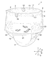
- this is a perspective view of the diaper 1, which has a front waistline region 2, a rear waistline region 3, and a crotch region 4, and the front and rear waistline regions 2, 3 are side edges 7,
- welding is performed at the joint portions 9 that are intermittently positioned in the vertical direction so that they are not easily peeled off during wearing.
- the crotch region 4 is formed by a body fluid-absorbing chassis 11, and the body fluid-absorbing chassis 11 extends from the crotch region 4 to the front waistline region 2 and the back waistline region 3, and leg opening 12 is formed on both sides of the crotch region 4.
- the waist opening 13 is defined by the front and rear waist areas 2 and 3.
- a gather 17 is formed on the periphery of the waistline opening 13 in the front and rear waistlines 2 and 3 by contraction of a waistline elastic member 16 described later.
- the front waistline region 2 is a central region in the lateral direction B of the diaper 1 and is a central inelastic region 21 that overlaps the body fluid-absorbing chassis 11 and lateral elasticity that is located on both sides of the body fluid-absorbing chassis 11 in the lateral direction B.
- a large number of gathers 23 are formed in the side elastic region 22 as the front waistline region 2 contracts in the lateral direction B.
- the front-rear direction and the vertical direction of the diaper are indicated by double-headed arrows A and C.
- the lateral direction B may be referred to as the waistline direction.
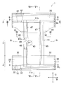
- FIG. 2 this is a partially broken plan view of the diaper 1 in a state where the diaper 1 is extended flatly by unbonding at the joint 9 of the diaper 1 of FIG. 1.
- the front waistline region 2 and the rear waistline region 3 are formed of an outer layer sheet 32 and an inner layer sheet 33 joined to the inner surface of the outer layer sheet 32 via a hot melt adhesive (not shown).
- the edges 32f and 32r are folded inside the diaper 1 along the periphery of the waistline opening 13 (see FIG. 1) to cover the front and rear end edges 11a and 11b of the bodily fluid absorbent chassis 11.
- a plurality of waistline elastic members 16 are interposed and fixed in an extended state via a hot melt adhesive (not shown).
- the outer layer sheet 32 is formed of a non-extensible sheet material that does not elastically extend in the lateral direction B, and preferably does not extend inelastically.
- sheet materials include, for example, spunbond fiber nonwoven fabrics, spunbond-meltblown-spunbond fiber nonwoven fabrics (SMS) having a mass per unit area of 10 to 40 g / m 2 , more preferably 15 to 30 g / m 2. Fiber nonwoven fabric) and air-through nonwoven fabric are used.
- the inner layer sheet 33 is formed of a sheet material that can be elastically expanded and contracted in the lateral direction B.
- the dimension L in the lateral direction B of the inner layer sheet 33 that is contracted and relaxed is formed.
- the inner layer sheet 33 is equivalent to 50 to 250% of the dimension L 0 so that 0 (not shown) is 1.5 to 3.5 times, more preferably 2 to 2.8 times.
- the outer layer sheet 32 is bonded to the outer layer sheet 32 at a mass ratio of 2 to 4 g / m 2 via a hot melt adhesive (not shown).
- the hot melt adhesive is applied to at least one of the joint surfaces.
- the expansion ratio of the inner layer sheet 33 in FIG. 2 is L as the dimension of the inner layer sheet 33 in the state of FIG.
- the sheet material of the inner layer sheet 33 that is elastically stretchable / shrinkable is a non-woven fabric formed of elastically stretchable / shrinkable fibers, for example, heat-sealable elastomer fibers, and has a unit area.
- the fiber nonwoven fabric used as the inner layer sheet 33 is preferably flexible, and is mixed with elastomer fibers or elastomer fibers forming the nonwoven fabric.
- the laminated fibers are preferably heat-fused by mechanically interlacing the fibers. This is because such a nonwoven fabric is generally softer and less irritating to the skin than a fiber nonwoven fabric in which a binder is used.
- the body fluid-absorbing chassis 11 includes an absorption structure 40 in which a panel-like body fluid-absorbing core member 43 is interposed between the liquid-permeable sheet 41 and the barrier sheet 42, and further joined to the outer surface of the barrier sheet 42. It includes a base sheet made of a thermoplastic synthetic fiber nonwoven fabric for making the outer surface of the body fluid absorbent chassis 11 feel like a cloth. Barrier cuffs 47 are provided on both side edges 46 of the body fluid absorbent chassis 11. .
- the barrier cuff 47 is formed by folding a substantially liquid-impervious fiber nonwoven fabric, the proximal edge 48 is joined to the barrier sheet 42 and the base sheet 44, and the distal edge 49 is in the crotch region 4. It is formed so as to be separated toward the skin.
- the barrier cuff 47 has an elastic member 47a extending in the longitudinal direction A between the folded portions, and when the elastic member 47a contracts, the distal edge 49 is located above the absorbent structure 40 (on the wearer's body side). ).
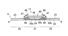
- FIG. 3 this is a view showing a section taken along line III-III of FIG.
- the rear waistline region 3 includes an outer layer sheet 32, a pattern-containing sheet 24 joined to the inner surface of the outer layer sheet 32 via a hot melt adhesive 50a in the central region in the lateral direction B, and an outer layer sheet via a hot melt adhesive 50b.
- 32 and the inner layer sheet 33 joined to the both side portions.
- the outer layer sheet 32 and the inner layer sheet 33 extend to the side edge 8 in the lateral direction B, and are peeled off by welding to the front waistline region 2 at the joint 9 (see FIGS. 1 and 2). It is joined so that there is no. However, in FIG. 3, illustration of the joint portion 9 is omitted.
- FIGS. 1 illustration of the joint portion 9 is omitted.
- the inner layer sheet 33 is joined to the outer layer sheet 32 and the design sheet 24 while being elastically extended in the lateral direction B, and forms a side elastic region 22 in the front waistline region 2 together with these sheets 32 and 24. ing.
- the inner layer sheet 33 in the central region in the lateral direction B, is not in an expanded state but in a relaxed state, and is not joined to the outer layer sheet 32 and the design sheet 24.
- the outer layer sheet 32 and the design sheet 24 joined thereto form a central inelastic region 21.
- the design sheet 24 does not elastically expand or contract, and a nonwoven fabric, a plastic film, paper, or the like formed of thermoplastic synthetic fiber on the design sheet 24 is used.
- the barrier sheet 42 is joined to the absorption structure 40 via the hot melt adhesive 50 c.
- the barrier cuff 47 in the body fluid absorbing chassis 11 has a proximal edge 48 joined to the outer surface of the barrier sheet 42 via a hot melt adhesive (not shown).
- a mode in which the body fluid absorbing chassis 11 is joined to the rear waistline region 3 is as follows. In the body fluid-absorbing chassis 11, the absorbent structure 40, the barrier sheet 42, and the proximal edge 48 of the barrier cuff 47 are integrally bonded to each other at both side edges 46 via a hot melt adhesive (not shown). ing.
- the cut surface extending in the lateral direction B across the inner layer sheet 33 in the front waistline region 2 has the same structure as that illustrated in FIG.
- the side elastic region 32 and the central inelastic region 21 are also formed in the front waistline region 2, and the side edge 46 of the body fluid absorbent chassis 11 is joined to the inner layer sheet 33 in the side elastic region 22. Has been. Therefore, also in the front waistline region 2, the force for extending the side elastic region 22 can be applied to the body fluid absorbent chassis 11.
- the inner layer sheet 33 and the design sheet 24 can be used even if the amount of the hot melt adhesive 50b is small. May be bonded so that they are not easily peeled off.
- the hot melt adhesive is used in the side elastic region 22.
- the hot melt adhesive 50b can be prevented from passing through the inner layer sheet 33 and coming into contact with the wearer's skin.
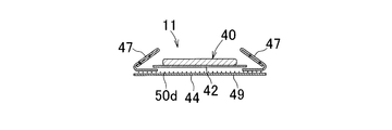
- FIG. 4 this is a view showing the IV-IV line section in FIG.
- the crotch region 4 of the diaper 1 is formed by the body fluid-absorbing chassis 11 and the outer layer sheet 44 joined to the barrier sheet 42 via the hot melt adhesive 50d.
- this is a view showing a cut surface taken along the line VV in FIG. 2, and the line VV cuts the side elastic region 22 in the front and rear waist regions 2 and 3 of FIG. .
- the inner layer sheet 33 in the side elastic region 22 is joined to the outer layer sheet 32 and the design sheet 24 via the hot melt adhesive 50b.
- the outer layer sheet 32 and the design sheet 24 extend from the edge 33 a of the inner layer sheet 33.
- FIG. 6 this is a view showing a section taken along the line VI-VI in FIG. 2, and the VV line cuts through the central inelastic region 21 in the front and rear waist regions 2 and 3 of FIG. .
- the design sheet 24 is bonded to the inner surface of the outer layer sheet 32 via a hot melt adhesive 50a, and the elastic member 16 is also connected via a hot melt adhesive (not shown).
- the patterned sheet 24 has an edge 24b adjacent to the crotch region 4 joined to the bottom sheet 44 via a hot melt adhesive 50e. In the preferred diaper 1, the edge 24b in FIG. It is joined.
- Such joining of the design sheet 24 and the bottom sheet 44 is performed between the front waist region 2 and the body fluid absorbent chassis 11 or between the rear waist region 3 and the body fluid absorbent chassis 11 when the diaper 1 is worn.
- the fingertips of the wearer and the like are prevented from entering inadvertently.
- the outer layer sheet 32 and the bottom sheet 44 can be joined. it can.
- the diaper 1 in this invention may be a mode in which the bottom sheet 44 and the design sheet 24 are not joined or a mode in which the bottom sheet 44 and the outer layer sheet 32 are not joined.
- the edge portions 33f and 33r of the outer layer sheet 32 folded back at the edge portion of the waistline opening 13 are joined to the outer layer sheet 32 facing the edge portion 33f via a hot melt adhesive (not shown).
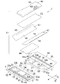
- FIG. 7 this is an exploded perspective view of the diaper 1.
- the outer layer sheet 32 in the front waistline region 2 has a plurality of elastic members 16 and an inner layer sheet 33 attached thereto, and has an end edge portion 32f shown in an upright state in the drawing.
- the end edge portion 32f is bent in the direction indicated by the arrow E so as to face the inner surface side of the diaper 1.
- the inner layer sheet 33 is on both sides of the outer layer sheet 32 in the lateral direction B, and is in a state released from elastic tension in the lateral direction B and a tension portion 33a that is elastically expanded in the lateral direction B.
- the relaxation site 33b the relaxation site 33b.
- tensile_strength part 33a is joined to the outer layer sheet
- FIG. The relaxation part 33b is a part adjacent to the lateral elastic region 23, and is not joined to the outer layer sheet 32, and forms a pleat.
- a portion between the relaxing portion 33 b and the relaxing portion 33 b facing each other in the lateral direction B and a portion including both the relaxing portions 33 b are the central inelastic region 21, and the central inelastic region 21.
- a sheet 24 with a pattern is joined to the inner surface of the outer layer sheet 32 in FIG.
- the inner layer sheet 33 is an outer layer in which the elastically stretchable first web 201 (see FIG. 8), which is the material, is stretched in the lateral direction B, for example, 150 to 350%.
- the sheet 32 is joined to the part to be the side elastic region 22 by the hot melt adhesive 50b and overlapped to the part to be the central inelastic region 21 without being joined.
- Virtual lines 56 and 57 in FIG. 7 indicate both edges of the first web 201.
- the first web 201 at the site to be the central inelastic region 21 is cut to bisect the first web 201 in the lateral direction B.
- the portions present in the central inelastic region 21 contract in opposite directions to form a relaxation portion 33b in the inner layer sheet 33.
- the first web 201 existing in the side elastic region 22 forms a tension portion 33 a in the inner layer sheet 33.
- the outer layer sheet 32 in the rear waistline region 3 of FIG. 7 also forms a part of the crotch region 4, and a plurality of elastic members 16 and the inner layer sheet 33 are attached, and stand up diagonally in the drawing. It has an end edge 32r.
- the end edge portion 32r is bent in the direction indicated by the arrow F so as to face the inner surface side of the diaper 1.
- the inner layer sheet 33 is on both sides of the outer layer sheet 32 and is divided into a tension part 33a and a relaxation part 33b.
- tensile_strength part 33a is joined to the outer layer sheet
- the relaxation portion 33b is adjacent to the side elastic region 22, is not joined to the outer layer sheet 32, and forms a wrinkle.
- the portion between the relaxing portion 33b and the relaxing portion 33b facing each other in the lateral direction B and the portion including both the relaxing portions 33b are the central inelastic region 21, and the central inelastic region 21
- a pattern-containing sheet 24 is joined to the inner surface of the outer layer sheet 32.
- FIG. 7 shows a planar shape of the body fluid-absorbing chassis 11 that is indicated by an imaginary line 58.
- the body fluid-absorbing chassis 11 placed on the inner surfaces of the front waistline region 2 and the rear waistline region 3 has a hot melt adhesive 50c (see FIG. 5) on each of the side elastic regions 22 inside the imaginary line 58 extending in the front-rear direction A. 3).
- the central inelastic region 21 is also joined via the hot melt adhesive 50c.
- the diaper 1 shown in FIGS. 2 to 7 is folded along a center line Q (see FIG. 1) that bisects the dimension in the front-rear direction A, and the side edges 7, 8 of the front-rear waist regions 2, 3 are folded. Is joined at the joint 9 (see FIG. 1), whereby the diaper 1 of FIG. 1 is obtained.
- FIG. 8 is a diagram showing a series of steps for forming the central inelastic region 21 and the side elastic region 22 in the front waistline region 2 by taking the front waistline region 2 in FIG. 7 as an example.
- step I the first web 201 for obtaining the inner layer sheet 33 is continuously supplied in the machine direction MD.
- the first web 201 has the same elastic extensibility as the inner layer sheet 33.
- the first web 201 was stretched to have a size 1.5 to 3.5 times in the machine direction MD. Supply in state.
- the cut line group 300 is formed at a constant pitch M with respect to the first web 201 in the stretched state to obtain the first processed web 211.
- a plurality of first cut lines 301 extending in a straight line in the machine direction MD are arranged in a cross direction CD with respect to the machine direction MD with a predetermined interval.
- the pitch M has a dimension equal to the lateral width of the diaper 1.
- the dimension in the crossing direction CD of the portion located between the adjacent first cut lines 301 and 301 is small depending on the expansion ratio in the machine direction MD and the length of the first cut line 301. In some cases, the change becomes remarkable. In that case, the first cut line 301 extending straight in the machine direction MD may change to form an oval opening 301a (see FIG. 10).
- Step II the second web 202 for manufacturing the outer layer sheet 32 is continuously supplied while being tensioned in the machine direction MD.
- the second web 202 does not stretch elastically like the outer layer sheet 32.
- an application area 306 of the hot melt adhesive 50b (see FIG. 3) is defined with a constant pitch M with respect to the second web 202, and an adhesive non-application area is defined between the application areas 306.
- the hot melt adhesive 50b is preferably applied intermittently so as not to hinder the elastic expansion and contraction of the first web 201 joined to the second web 202 in the step III described later.
- the dimension in the machine direction MD of the application area 306 is about twice the dimension in the lateral direction B of the side elastic area 22 in the diaper 1 of FIG.
- step III the first processed web 211 is overlapped on the second processed web 212, and both the webs 211 and 212 are joined by the hot melt adhesive 50b to obtain the third processed web 213.
- the two webs 211 and 212 divide the non-application area 307 into two in the machine direction so that the cut line group 300 is located between the adjacent application areas 306 and 306. Positioning is performed so as to be adjacent to one side of the center line S1.
- a second cut line 302 and a third cut line 303 are formed for each of the cut line groups 300 of the first processed web 211 in the third processed web 213.
- the second cut lines 302 are formed so as to intersect each of the adjacent first cut lines 301 in the intersecting direction CD.
- the third cut line 303 is formed so as to intersect the side edge 211a of the first processed web 211 and the first cut line 301 adjacent to the side edge 211a, and the side edge of the first processed web 211 In some cases, it is formed so as to intersect 211b and the first cut line 301 adjacent to the side edge 211b.
- the second and third cut lines 302 and 303 are formed in this way, in the first processed web 211, the third cut lines 303 positioned above and below in the drawing pass through the first cut line 301 and the second cut line 302. And the first processed web 211 can be divided in the machine direction MD. In the first processed web 211 after the division, the portions 313 and 314 located on both sides of the cut line group 300 are elastically contracted in opposite directions, and the first and second processed webs 211 and 212 are joined. Stops in the vicinity of the coating area 306.
- FIG. 9 is a partial view of the fourth processed web 214 obtained by shrinking the non-application areas 307a and 307b of the first process web 211 separated by the non-application area 307 along the center line S1 in step IV of FIG. .
- the planar shape of the body fluid-absorbing chassis 11 attached to the fourth processed web 214 is indicated by imaginary lines.
- a line that bisects the coating region 306 in the fourth processed web 214 in the machine direction MD is indicated by a center line S2.
- the coating area 306 has a dimension approximately twice the lateral dimension of the lateral elastic area 22 in FIG. Has the same dimension as the lateral dimension of the central inelastic region 21 in FIG.
- the body fluid-absorbing chassis 11 is placed on the fourth processed web 214 like a virtual line, and bonded to the first processed web 211 in the application region 306 with the hot melt adhesive 50c (see FIG. 3).
- the fourth processed web 214 is cut at the center line S2 in the application region 306, a composite body in which the body fluid-absorbing chassis 11 is joined to the front waistline region 2 in FIG. 7 can be obtained.
- the part including the bisected application region 306 forms the side elastic region 22 in FIG. 7, the part between the application regions 306 and 306 forms the central inelastic region 21,
- Each of the non-application areas 307a and 307b which are elastically contracted becomes the relaxation part 33b in FIG. Incidentally, the non-application areas 307a and 307b come into contact with each other at the site where the cut line group 300 exists when they are extended toward the center of the central inelastic area 21.
- the central inelastic region 21 and the side elastic region 22 in the rear waistline region 3 can also be obtained by the same process as in the front waistline region 2.
- the elastic inner layer sheet used only in the side elastic region 22 33 can be carried on the second processed web 212 that is a continuum of the outer layer sheet 32, so that the inner layer sheet 33 can be easily conveyed in the diaper 1 and the production speed of the diaper 1 can be improved.
- the second and third cut lines 302 and 303 are also formed on the second processed web 212 that overlaps the first processed web 211. In some cases, the second and third cut lines 302 and 303 that are separated from each other do not divide the first processed web 211 or form a large opening in the second processed web 212.
- the appearance of the outer layer sheet 33 in the diaper 1 and the pattern 24a of the pattern sheet 24 bonded to the outer layer sheet 33 are not significantly damaged.
- the second and third cut lines 302 and 303 are arranged in the lateral direction B of the central inelastic region 21. It is preferable to be formed at a position deviated from the center of the diaper 1 in the lateral direction B from the center of the diaper 1 in the lateral direction B.
- the first cut line 301 in FIG. 10 forms an opening 301a having a large area.
- an opening 301a which is a portion between the first slits 301 and 301 is provided. Since the width of the portion 301b between the first hole 301a and the opening 301a is reduced, the lengths of the second, third, and fourth cut lines 312, 313, and 314 can be shortened. At the same time, it can be greatly separated in the cross direction CD. In this case, in the third processed web 213 and the fourth processed web 214 in FIG. 8, damage to the second processed web 212 caused by the second, third, and fourth cut lines 302, 303, and 304 can be reduced. .
- the diaper 1 In the illustrated diaper 1, gathering does not occur in the body fluid-absorbing chassis 11 itself due to the use of an elastic member, and gathering is reliably prevented from occurring in the central inelastic region 21 of the front and rear waist regions 2 and 3. Therefore, the diaper 1 has good visibility of the pattern 24a. Even when an indicator for notifying urine is excreted in the diaper 1 is attached to the inside of the barrier sheet 42 in the body fluid-absorbing chassis 11, the visibility of the indicator is good.
- the diaper 1 according to the present invention may be one that does not use the design sheet 24 and / or the indicator, and the central inelastic region 21 and the side elastic region 22 are the front waistline region 2 and the rear waistline. It may be formed only in one of the areas 3.
Landscapes
- Health & Medical Sciences (AREA)
- Engineering & Computer Science (AREA)
- Life Sciences & Earth Sciences (AREA)
- Biomedical Technology (AREA)
- Heart & Thoracic Surgery (AREA)
- Vascular Medicine (AREA)
- Epidemiology (AREA)
- Animal Behavior & Ethology (AREA)
- General Health & Medical Sciences (AREA)
- Public Health (AREA)
- Veterinary Medicine (AREA)
- Manufacturing & Machinery (AREA)
- Absorbent Articles And Supports Therefor (AREA)
Abstract
前胴回り域および後胴回り域の少なくとも一方に中央非弾性域を有する使い捨てのパンツ型おむつおよびその製造方法を提供する。 使い捨てのパンツ型おむつの前後胴回り域2,3が弾性的に伸長することのない外層シート32と、弾性的に伸長可能な内層シート33とによって形成される。その胴回り域のうちの側方弾性域22においては、内層シート33が外層シート32の内面に伸長状態で接合し、中央非弾性域21においては、内層シート33が横方向Bへ二分されていて、側方弾性域22に隣接する部位において弾性的に収縮して弛緩した状態にある。
Description
この発明は、使い捨てのパンツ型おむつおよびその製造方法に関する。
従来、使い捨て吸収性物品の一つとして、前後胴回り域のうちの少なくとも一方の胴回り域が胴回り方向への弾性的な伸長性を有する使い捨てのパンツ型おむつが知られている。また、その胴回り域のうちで、体液吸収構造体と重なり合う中央部位が伸長状態にある弾性部材を含むことがなく、体液吸収構造体の両側に位置する側方部位が伸長状態にある弾性部材を含むことによって、中央部位にはギャザーが形成されていないが、側方部位にはギャザーが形成されている使い捨ておむつも知られている。
たとえば、特開2001-145666号公報(特許文献1)に記載された吸収性物品の一例は、使い捨てのパンツ型おむつであって、胴周囲弾性部材が吸収体の存在しない部位においては、弾性伸縮性が発現されるように伸長状態で固定され、吸収体が存在する部位においては、固定されずに切断されており、実質的に弾性伸縮性が発現されずかつギャザーが形成されていない。
また、特開2001-286504号公報(特許文献2)に記載の吸収性物品の製造方法では、胴周囲弾性部材を2枚の外層シートで狭持する。吸収体が存在しない部位の胴周囲弾性部材が固定されている。吸収体が存在する部位の胴周囲弾性部材は、加熱処理および加圧処理により切断して固定されている。
特許文献1に開示の吸収性物品における胴周囲弾性部材は、吸収体が存在する部位においては他の部材に固定されておらず、胴周囲弾性部材を挟む弾性部材固定シートと補助シートともに切断されている。このため、これら両シートにはすべての胴周囲弾性部材と交差する方向へ延びる大きな開口が形成されることを避けることができない。また、その開口や胴周囲弾性部材の乱れたカットエンドを隠すための隠蔽シートが必要になる。
また、特許文献2に記載の製造方法は、幅の広い帯状の胴周囲弾性部材に対して適用することができない。
この発明では、このような従来技術の問題を解消することが可能な使い捨てのパンツ型おむつとその製造方法との提供を課題にしている。
前記課題を解決するためのこの発明は、使い捨てのパンツ型おむつに係る第1発明と、その製造方法に係る第2発明とを含む。
前記第1発明は、縦方向に直交する横方向を有し、前胴回り域と、後胴回り域と、股下域と、前記股下域から前記前後胴回り域それぞれにまで延びる体液吸収性シャーシと、前記前後胴回り域のうちの少なくとも一方の胴回り域において、前記体液吸収性シャーシの両側方それぞれに横方向へ弾性的に伸長可能な側方弾性域と、前記側方弾性域どうしの間に弾性的にも非弾性的にも伸長することのない中央非弾性域とを含む使い捨てのパンツ型おむつである。
前記第1発明が特徴とするところは、次のとおりである。すなわち、前記少なくとも一方の胴回り域は、その横方向へ弾性的に伸長することのない外層シートと、前記横方向へ弾性的に伸長可能であって前記外層シートの内面側に位置する内層シートとを含む。前記側方弾性域においては、前記内層シートが前記外層シートの内面に伸長状態で接合し、前記中央非弾性域においては、前記内層シートが前記横方向へ二分されていて前記側方弾性域に隣接する域において弾性的に弛緩した状態にある。
第1発明の実施態様の一つにおいて、前記中央非弾性域が前記体液吸収性シャーシの外側に形成されている。
第1発明の実施態様の他の一つにおいて、前記体液吸収性シャーシが前記おむつの横寸法を二等分する中心線の両側に側縁部を有し、前記側縁部が前記側方弾性域に接合している。
第1発明の実施態様の他の一つにおいて、前記体液吸収性シャーシがバリヤシートを有し、前記中央非弾性域が前記バリヤシートの外側から前記体液吸収性シャーシに接合している。
第1発明の実施態様の他の一つにおいて、前記中央非弾性域と前記体液吸収性シャーシとの間には、前記おむつにおいて尿が排泄されたことを知らせるためのインジケータが介在している。
第1発明の実施態様の他の一つにおいて、前記中央非弾性域では、図柄が表わされたシートが前記外層シートの前記内面に接合し、前記外層シートの外側から前記図柄が視認可能である。
第1発明の実施態様の他の一つにおいて、前記内層シートは、弾性的に伸長可能な弾性材料と、弾性的に伸長することのない非弾性材料とによって形成されている弾性的に伸長可能な弾性繊維不織布である。
第1発明の実施態様の他の一つにおいて、前記内層シートが熱可塑性合成繊維で形成された不織布と、前記横方向へ弾性的に伸長した状態で前記不織布に接合している複数条の糸状ゴムおよび帯状ゴムの一つで形成されている。
第1発明の実施態様の他の一つにおいて、前記内層シートが前記横方向へ弾性的に伸長可能な熱可塑性合成樹脂のフィルムで形成されている。
前記第2発明は、体液吸収性シャーシが股下域から前後胴回り域それぞれにまで延びる体液吸収性シャーシと、前記前後胴回り域のうちの少なくとも一方の胴回り域において、前記体液吸収性シャーシの両側方それぞれに前記横方向へ弾性的に伸長可能な側方弾性域と、前記側方弾性域どうしの間に弾性的にも非弾性的にも伸長することのない中央非弾性域とを含む使い捨てのパンツ型おむつの製造方法である。
前記第2発明が特徴とするところは、次のとおりである。
a.機械方向へ弾性的に伸長可能な第1ウエブを機械方向へ伸長状態で連続的に供給する工程と、
b.前記第1ウエブに対して、前記機械方向へ所要の長さを有するとともに前記機械方向に対する交差方向において所要の間隔で並ぶ互いに並行な複数条の第1カットラインによって構成されたカットライン群を形成するとともに、前記カットライン群が前記機械方向において前記おむつの横寸法に相当するピッチで並ぶ前記カットライン群の複数を形成することによって、前記第1ウエブから第1加工ウエブを得る工程と、
c.前記機械方向において弾性的に伸長することのない第2ウエブを前記機械方向へ緊張状態で供給する工程と、
d.前記第2ウエブに対して前記第1加工ウエブを重ねるとともに、隣り合う前記カットライン群どうしの間において前記第1ウエブと前記第2ウエブとが接合状態にある接合域と、前記カットライン群の形成された部位およびそれに隣接する部位とにおいて前記第1加工ウエブと前記第2ウエブとが非接合状態にある非接合域とを形成して、前記第1加工ウエブと前記第2ウエブとから第2加工ウエブを得る工程と、
e.前記第2加工ウエブにおける前記第1加工ウエブの前記カットライン群において、前記交差方向で隣り合う前記第1カットラインそれぞれと交差する第2カットラインと、前記第1加工ウエブにおいて前記機械方向へ延びる両側縁それぞれと前記両側縁それぞれに隣接する前記第1カットラインのそれぞれとに交差する第3カットラインとを形成して、前記第1加工ウエブを前記カットライン群の形成されている域において前記機械方向へ分断して、前記機械方向において該域の両側に位置する第2,第3部位を互いに反対方向へ収縮させて第3加工ウエブを得る工程と、
f.前記第3加工ウエブに前記体液吸収性シャーシの一部分を接合する工程とを含み、
g.前記工程fの後に、前記機械方向における前記接合域の中央で前記第3加工ウエブを分断して、前記第3加工ウエブにおける前記接合域の一部分からは前記側方弾性域を形成し、前記カットライン群が形成されていた域からは前記中央非弾性域を形成する。
b.前記第1ウエブに対して、前記機械方向へ所要の長さを有するとともに前記機械方向に対する交差方向において所要の間隔で並ぶ互いに並行な複数条の第1カットラインによって構成されたカットライン群を形成するとともに、前記カットライン群が前記機械方向において前記おむつの横寸法に相当するピッチで並ぶ前記カットライン群の複数を形成することによって、前記第1ウエブから第1加工ウエブを得る工程と、
c.前記機械方向において弾性的に伸長することのない第2ウエブを前記機械方向へ緊張状態で供給する工程と、
d.前記第2ウエブに対して前記第1加工ウエブを重ねるとともに、隣り合う前記カットライン群どうしの間において前記第1ウエブと前記第2ウエブとが接合状態にある接合域と、前記カットライン群の形成された部位およびそれに隣接する部位とにおいて前記第1加工ウエブと前記第2ウエブとが非接合状態にある非接合域とを形成して、前記第1加工ウエブと前記第2ウエブとから第2加工ウエブを得る工程と、
e.前記第2加工ウエブにおける前記第1加工ウエブの前記カットライン群において、前記交差方向で隣り合う前記第1カットラインそれぞれと交差する第2カットラインと、前記第1加工ウエブにおいて前記機械方向へ延びる両側縁それぞれと前記両側縁それぞれに隣接する前記第1カットラインのそれぞれとに交差する第3カットラインとを形成して、前記第1加工ウエブを前記カットライン群の形成されている域において前記機械方向へ分断して、前記機械方向において該域の両側に位置する第2,第3部位を互いに反対方向へ収縮させて第3加工ウエブを得る工程と、
f.前記第3加工ウエブに前記体液吸収性シャーシの一部分を接合する工程とを含み、
g.前記工程fの後に、前記機械方向における前記接合域の中央で前記第3加工ウエブを分断して、前記第3加工ウエブにおける前記接合域の一部分からは前記側方弾性域を形成し、前記カットライン群が形成されていた域からは前記中央非弾性域を形成する。
第2発明の実施態様の一つにおいて、前記第1ウエブが、弾性的に伸長可能な弾性糸と、弾性的に伸長することのない非弾性糸とによって形成されている弾性的に伸長可能な不織布である。
第2発明の実施態様の他の一つにおいて、前記第1ウエブが、熱可塑性合成繊維で形成された不織布と、前記機械方向へ弾性的に伸長した状態で前記不織布に接合している複数条の糸状ゴムおよび帯状ゴムの一つで形成されている。
第2発明の実施態様の他の一つにおいて、前記第1ウエブが、前記機械方向へ弾性的に伸長可能な熱可塑性合成樹脂のフィルムで形成されている。
この発明の第1発明では、前後胴周り域のうちの少なくとも一方の胴回り域が弾性的に伸長することのない外層シートと、弾性的に伸長可能な内層シートとによって形成されている。胴回り域のうちの側方弾性域においては、内層シートが外層シートの内面に伸長状態で接合し、胴回り域のうちの中央非弾性域においては、内層シートが横方向へ二分されていて側方弾性域に隣接する部位において弾性的に弛緩した状態にあるから、その弛緩した内層シートは外層シートの外側からは見え難く、おむつの外観を悪くすることがない。
この発明の第2発明では、弾性的に伸長させた状態の第1ウエブと弾性的に伸長することがなく緊張状態にある第2ウエブとが形成する第2加工ウエブにおいて、それに含まれる第1加工ウエブの複数条の第1カットラインと交差し、機械方向において互いに離間している第2,第3カットラインを形成して第1加工ウエブをその第1域において分断して弾性的に収縮させるから、第2加工ウエブにおける第2ウエブは第1域に相当する域が横方向へ弾性的に収縮することがなく、体液吸収性シャーシの外側に位置させる中央非弾性域として使用することができる。
図面を参照してこの発明の詳細を説明すると、以下のとおりである。
図1を参照すると、これは、おむつ1の斜視図であって、前胴回り域2と、後胴回り域3と、股下域4とを有し、前後胴回り域2,3は側縁部7,8の内面が互いに重なった状態で、縦方向へ断続的に位置する接合部9において溶着することにより着用中に容易に剥がれることがないように接合している。股下域4は、体液吸収性シャーシ11によって形成され、体液吸収性シャーシ11が股下域4から前胴回り域2と後胴回り域3へ延びていて、股下域4の両側には脚回り開口12が画定され、前後胴回り域2,3により胴回り開口13が画定されている。前後胴回り域2,3における胴回り開口13の周縁部には、後記胴回り弾性部材16が収縮することによってギャザー17が形成されている。前胴回り域2は、おむつ1の横方向Bの中央域であって体液吸収性シャーシ11に重なる中央非弾性域21と、横方向Bにおいて体液吸収性シャーシ11の両側それぞれに位置する側方弾性域22とを有し、中央非弾性域21にはギャザーが殆ど形成されておらず、魚の図柄24aが見えている。側方弾性域22には前胴回り域2が横方向Bにおいて収縮することによって多数のギャザー23が形成されている。図1には、おむつの前後方向と縦方向とが双頭矢印A,Cで示されている。なお、おむつ1において、横方向Bを胴回り方向と呼ぶことがある。
図2を参照すると、これは、図1のおむつ1の接合部9における接合を解いて、おむつ1を平らに伸展した状態の部分破断平面図である。前胴回り域2と後胴回り域3とは、外層シート32と、外層シート32の内面にホットメルト接着剤(図示せず)を介して接合する内層シート33とから形成され、外層シート32は端縁部32f,32rが胴回り開口13(図1参照)の周縁に沿っておむつ1の内側に折られて、体液吸収性シャーシ11の前後端縁部11a,11bを覆っている。折られた外層シート32どうしの間にはホットメルト接着剤(図示せず)を介して複数条の胴回り弾性部材16が伸長状態で介在固定されている。外層シート32は、横方向Bへ弾性的に伸長することのない、好ましくは非弾性的にも伸長することのない非伸長性のシート材料によって形成されている。そのようなシート材料は、一例としては、単位面積当たりの質量が10~40g/m2、より好ましくは15~30g/m2のスパンボンド繊維不織布、スパンボンド-メルトブローン-スパンボンド繊維不織布(SMS繊維不織布)、エアスルー不織布が用いられる。
内層シート33は、横方向Bにおいて弾性的に伸長、収縮可能なシート材料によって形成されていて、側方弾性域22においては、収縮して弛緩状態にある内層シート33の横方向Bにおける寸法L0(図示せず)が1.5~3.5倍となるように、より好ましくは2~2.8倍となるように内層シート33が寸法L0の50~250%に相当する分だけ伸長された状態で、質量2~4g/m2の割合で外層シート32にホットメルト接着剤(図示せず)を介して接合している。ホットメルト接着剤は、その接合面の少なくとも一方に塗布される。ただし、図2における内層シート33の伸長倍率は、図2の状態にある内層シート33の寸法をLとし、図2の外層シート32から剥がして収縮させた内層シート33の寸法をL0とし、これらLとL0との比、L/L0によって求められる値である。弾性的に伸長、収縮可能な内層シート33のシート材料は、その一例として、弾性的に伸長、収縮可能な繊維によって形成された不織布、たとえば熱融着性のエラストマー繊維で形成されていて単位面積当たりの質量が15~50g/m2、より好ましくは25~40g/m2である弾性的に伸長、収縮可能なエアスルー不織布、スパンボンド不織布等が用いられる。内層シート33は、おむつ着用者(図示せず)の肌に触れるから、内層シート33として使用する繊維不織布は柔軟なものであることが好ましく、その不織布を形成するエラストマー繊維やエラストマー繊維と混合または積層される繊維は、繊維どうしが機械的に交絡して加熱融着されていることが好ましい。そのような不織布は繊維どうしがバインダーが用いられている繊維不織布よりも一般的に柔軟で肌を刺激することが少ないからである。
体液吸収性シャーシ11は、透液性シート41とバリヤシート42との間にパネル状の体液吸収性の芯材43が介在する吸収構造体40を含み、さらにバリヤシート42の外面に接合して体液吸収性シャーシ11の外面を布様の肌触りにするための熱可塑性合成繊維不織布で形成されたベースシートを含み、体液吸収性シャーシ11の両側縁部46には、バリヤカフ47が設けられている。バリヤカフ47は、実質的に不透液性の繊維不織布が折り重ねられていて、近位縁48がバリヤシート42とベースシート44とに接合し、遠位縁49が股下域4において着用者の肌に向かって離間可能に形成されている。バリヤカフ47は、折り重ねられた部分の間において縦方向Aへ伸長状態で延びる弾性部材47aを有し、弾性部材47aが収縮すると遠位縁49が吸収構造体40から上方(着用者の身体側)へ離間する。
図3を参照すると、これは、図2のIII-III線切断面を示す図である。後胴回り域3は、外層シート32と、横方向Bの中央域において外層シート32の内面にホットメルト接着剤50aを介して接合する図柄入りシート24と、ホットメルト接着剤50bを介して外層シート32の両側方部分に接合している内層シート33とから形成されている。外層シート32と内層シート33とは、横方向Bにおいて、側縁部8にまで延びていて、接合部9(図1,2参照)では前胴回り域2に対して溶着することにより剥離することがないように接合している。ただし、図3では、接合部9の図示が省略されている。なお、図3および図4~6では外層シート32等の各部材と各ホットメルト接着剤とを明示するために、互いに接触すべき部材のいくつかが離間した状態で示されている。内層シート33は、横方向Bへ弾性的に伸長された状態で外層シート32と図柄入りシート24とに接合して、これらシート32,24とともに前胴回り域2における側方弾性域22を形成している。後記図7において明らかなように、横方向Bの中央域では、内層シート33が伸長した状態ではなくて弛緩した状態にあって外層シート32と図柄シート24とに接合しておらず、その中央域では外層シート32とそれに接合する図柄入りシート24とが中央非弾性域21を形成している。なお、図柄入りシート24は、弾性的に伸長、収縮することがなく、図柄入りシート24に熱可塑性合成繊維で形成された不織布、プラスチックフィルム、紙等が使用される。
図3における後胴回り域3の内面側では、吸収構造体40にバリヤシート42がホットメルト接着剤50cを介して接合している。また、体液吸収性シャーシ11におけるバリヤカフ47は、近位縁48がバリヤシート42の外面にホットメルト接着剤(図示せず)を介して接合している。体液吸収性シャーシ11が後胴回り域3に接合する態様は、次のとおりである。体液吸収性シャーシ11では、その両側縁部46において吸収構造体40と、バリヤシート42と、バリヤカフ47の近位縁48とがホットメルト接着剤(図示せず)を介して一体的に接合している。その両側縁部46は、後胴回り域3における側方弾性域22を形成している部分の内層シート33に横方向Bの寸法が5~30mm程度となる範囲において重なり、ホットメルト接着剤50cを介して接合している。それゆえ、着用したおむつ1において、側方弾性域22に対して横方向Bへ、または胴回り方向へ弾性的に伸長させる力が作用すると、その力が体液吸収性シャーシ11にも作用して、体液吸収性シャーシ11を着用者の肌に接近、または密着させることができる。なお、図示してはいないが、前胴回り域2において内層シート33を横断して横方向Bへ延びている切断面は、図3に例示の構造と同じ構造を有している。すなわち、前胴回り域2にも側方弾性域32と中央非弾性域21とが形成されていて、体液吸収性シャーシ11の側縁部46が側方弾性域22における内層シート33に対して接合されている。それゆえ、前胴回り域2においてもまた、側方弾性域22を伸長させるときの力を体液吸収性シャーシ11に作用させることができる。
図3において、内層シート33と接合している図柄入りシート24が不織布ではなくてプラスチックフィルムで形成されているときには、ホットメルト接着剤50bの使用量が少なくても内層シート33と図柄入りシート24とを容易に剥離することがないように接合しておくことができる場合がある。その場合の側方弾性域22における内層シート33は接合部9における外層シート32と図柄入りシート24のプラスチックフィルムとに対して強固に接合しているので、側方弾性域22においてホットメルト接着剤50bの使用量を少なくして、そのホットメルト接着剤50bが内層シート33を通り抜けて着用者の肌に接触することを防ぐことができる。
図4を参照すると、これは、図2におけるIV-IV線切断面を示す図である。おむつ1の股下域4は、体液吸収性シャーシ11と、これのバリヤシート42にホットメルト接着剤50dを介して接合する外層シート44とによって形成されている。
図5を参照すると、これは、図2におけるV-V線切断面を示す図であって、V-V線は図1の前後胴回り域2,3における側方弾性域22を縦断している。側方弾性域22における内層シート33は、ホットメルト接着剤50bを介して外層シート32と図柄入りシート24とに接合している。外層シート32と図柄入りシート24とは、内層シート33の縁部33aから延出している。
図6を参照すると、これは、図2におけるVI-VI線切断面を示す図であって、V-V線は図1の前後胴回り域2,3における中央非弾性域21を縦断している。前後胴回り域2,3のそれぞれにおいて、外層シート32の内面には、図柄入りシート24がホットメルト接着剤50aを介して接合するとともに、弾性部材16もホットメルト接着剤(図示せず)を介して固定している。図柄入りシート24は、股下域4に隣接する端縁部24bがホットメルト接着剤50eを介して底部シート44に接合しており、好ましいおむつ1では図5における端縁部24bも底部シート44に接合している。図柄入りシート24と底部シート44とのこのような接合は、おむつ1を着用したときなどにおいて、前胴回り域2と体液吸収性シャーシ11との間や後胴回り域3と体液吸収性シャーシ11の間に着用者等の指先が不用意に入ることを防いでいる。なお、図柄入りシート24が使用されていないおむつ1や外層シート32が図柄入りシート24から股下域4に向かって延出しているおむつ1では、外層シート32と底部シート44とを接合することができる。ただし、この発明におけるおむつ1は、底部シート44と図柄入りシート24とが接合していない態様や底部シート44と外層シート32とが接合していない態様のものであってもよい。胴回り開口13の縁部で折り返されている外層シート32の端縁部33f,33rはそれと向かい合う外層シート32に対してホットメルト接着剤(図示せず)を介して接合している。
図7を参照すると、これは、おむつ1についての分解斜視図である。前胴回り域2における外層シート32には、複数条の弾性部材16と内層シート33とが取り付けられていて、図では斜めに起立した状態で示されている端縁部32fを有する。端縁部32fはおむつ1の内面側に向かうように矢印Eで示される方向へ折曲される。内層シート33は、外層シート32における横方向Bの両側にあって、横方向Bへ弾性的に伸長された状態にある緊張部位33aと、横方向Bへの弾性的な伸長から解放された状態にある弛緩部位33bとに分けられている。緊張部位33aは、ホットメルト接着剤50b(図3参照)を介して外層シート32に接合して側方弾性域22を形成している。弛緩部位33bは、側方弾性域23に隣接する部位であって、外層シート32には接合しておらず、ひだを形成している。前胴回り域2において、横方向Bで対向する弛緩部位33bと弛緩部位33bとの間の部位とこれら両弛緩部位33bとを含む部位は中央非弾性域21であって、その中央非弾性域21における外層シート32の内面には図柄入りシート24(図3参照)が接合している。
外層シート32に対して内層シート33をかように配置する方法の詳細は、後記図8,9のとおりであって、それを図7を参照しながら略述すると次のとおりである。すなわち、内層シート33は、その材料となる弾性的に伸長可能な第1ウエブ201(図8参照)を横方向Bへたとえば150~350%伸長した状態で、横方向Bへ緊張させてある外層シート32のうちの側方弾性域22とすべき部位にホットメルト接着剤50bで接合し、かつ中央非弾性域21とすべき部位には接合することなく重ねる。図7における仮想線56,57は、その第1ウエブ201の両縁部を示している。しかる後に、中央非弾性域21とすべき部位にある第1ウエブ201を切断して第1ウエブ201を横方向Bにおいて二分する。二分された第1ウエブ201は、中央非弾性域21に存在していた部分が互いに反対方向へ収縮して、内層シート33における弛緩部位33bを形成する。側方弾性域22に存在していた第1ウエブ201は、内層シート33における緊張部位33aを形成する。
図7の後胴回り域3における外層シート32は、股下域4の一部分をも形成しており、複数条の弾性部材16と、内層シート33とが取り付けられていて、図では斜めに起立している端縁部32rを有する。端縁部32rは、おむつ1の内面側に向かうように矢印Fで示される方向へ折曲される。内層シート33は、外層シート32の両側にあって、緊張部位33aと、弛緩部位33bとに分けられている。緊張部位33aは、ホットメルト接着剤50bを介して外層シート32に接合して側方弾性域22を形成している。弛緩部位33bは、側方弾性域22に隣接していて外層シート32には接合しておらず、しわを形成している。後胴回り域3において横方向Bで対向する弛緩部位33bと弛緩部位33bとの間の部位と、これら両弛緩部位33bとを含む部位は中央非弾性域21であって、その中央非弾性域21における外層シート32の内面には図柄入りシート24が接合している。後胴回り域3における内層シート33のこのような配置は、前胴回り域2における内層シート33の場合と同様にして得ることができる。
図7に仮想線58で示されているのは、体液吸収性シャーシ11の平面形状である。前胴回り域2と後胴回り域3との内面に載せた体液吸収性シャーシ11は、前後方向Aへ延びる部分の仮想線58の内側で側方弾性域22のそれぞれにホットメルト接着剤50c(図3参照)を介して接合される。中央非弾性域21に対しても、ホットメルト接着剤50cを介して接合される。
図2~7に示されたおむつ1は、前後方向Aの寸法を二等分する中心線Q(図1参照)に沿って折り重ねられ、前後胴回り域2,3の側縁部7,8を接合部9(図1参照)で接合することにより、図1のおむつ1となる。
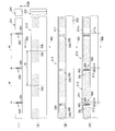
図8は、図7における前胴回り域2を例にとって、前胴回り域2に中央非弾性域21と側方弾性域22とを形成する一連の工程を示す図である。
工程Iでは、内層シート33を得るための第1ウエブ201を機械方向MDへ連続的に供給する。第1ウエブ201は、内層シート33と同じ弾性的な伸長性を有するもので、工程Iでは、第1ウエブ201を機械方向MDにおいて1.5~3.5倍の寸法となるように伸長した状態で供給する。工程Iではまた、伸長状態にある第1ウエブ201に対して、カットライン群300を一定のピッチMで形成して第1加工ウエブ211を得る。カットライン群300では、機械方向MDへ直状に延びる複数条の第1カットライン301が機械方向MDに対する交差方向CDに所要の間隔をあけて並んでいる。ピッチMは、おむつ1の横幅に等しい寸法を有している。第1加工ウエブ211では、機械方向MDにおける伸長倍率や第1カットライン301の長さの如何によって、隣り合う第1カットライン301と301との間に位置する部分の交差方向CDにおける寸法が小さくなるように変化することが顕著になる場合がある。その場合には、機械方向MDへ直状に延びていた第1カットライン301が長円形の開孔301a(図10参照)を形成するように変化することがある。
工程IIでは、外層シート32を製造するための第2ウエブ202を機械方向MDへ緊張させながら連続的に供給する。第2ウエブ202は、外層シート32と同じように弾性的に伸長することがない。また、工程IIでは、第2ウエブ202に対してホットメルト接着剤50b(図3参照)の塗布域306を一定のピッチMで画定するとともに塗布域306の間に接着剤の非塗布域を画定して、第2加工ウエブ212を得る。ホットメルト接着剤50bは、後記工程IIIにおいて第2ウエブ202に接合される第1ウエブ201の弾性的な伸長、収縮を妨げることがないように、間欠的に塗布されていることが好ましい。しかし、そのための塗工機の種類には格別の規定がない。塗布域306の機械方向MDにおける寸法は、図7のおむつ1における側方弾性域22の横方向Bの寸法の約2倍である。
工程IIIでは、第1加工ウエブ211を第2加工ウエブ212に重ねてホットメルト接着剤50bによって両ウエブ211と212とを接合して第3加工ウエブ213を得る。そのときに、両ウエブ211と212とは、カットライン群300が隣り合う塗布域306と306との間に来るように、さらに具体的には、非塗布域307を機械方向に二等分する中心線S1の一側に隣接するように、位置合わせしておく。
工程IVでは、第3加工ウエブ213における第1加工ウエブ211のカットライン群300のそれぞれに対して、第2カットライン302と、第3カットライン303とを形成する。第2カットライン302は、交差方向CDにおいて隣り合う第1カットライン301のそれぞれと交差するように形成する。第3カットライン303には、第1加工ウエブ211の側縁211aと、その側縁211aに隣接する第1カットライン301とに交差するように形成する場合と、第1加工ウエブ211の側縁211bと、その側縁211bに隣接する第1カットライン301とに交差するように形成する場合とがある。このように第2,第3カットライン302,303を形成すると、第1加工ウエブ211では、図の上下に位置する第3カットライン303どうしが第1カットライン301と第2カットライン302を介してつながり、第1加工ウエブ211を機械方向MDにおいて分断することができる。分断後の第1加工ウエブ211は、カットライン群300の両側それぞれに位置していた部位313,314が互いに反対方向へ弾性的に収縮して、第1,第2加工ウエブ211,212が接合している塗布域306の近傍で停止する。
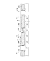
図9は、図8の工程IVにおいて中心線S1で非塗布域307で分けられる第1加工ウエブ211の非塗布域307a,307bが収縮することによって得られる第4加工ウエブ214の部分図である。図9にはまた、第4加工ウエブ214に対して取り付けられる体液吸収性シャーシ11の平面形状が仮想線で示されている。また、第4加工ウエブ214における塗布域306を機械方向MDにおいて二等分する線が中心線S2で示されている。かような第4加工ウエブ224では、機械方向MDにおいて、塗布域306が図7における側方弾性域22の横寸法の約2倍の寸法を有し、塗布域306と306との間の域が図7における中央非弾性域21の横寸法と同じ寸法を有している。それゆえ、第4加工ウエブ214に対して、体液吸収性シャーシ11を仮想線の如くに置いて、塗布域306における第1加工ウエブ211に対してホットメルト接着剤50c(図3参照)で接合した後、第4加工ウエブ214を塗布域306における中心線S2において切断すると、図7における前胴回り域2に体液吸収性シャーシ11が接合している複合体を得ることができる。その複合体においては、二等分された塗布域306を含む部位が図7における側方弾性域22を形成し、塗布域306と306との間の部位が中央非弾性域21を形成し、弾性的に収縮した非塗布域307a,307bのそれぞれが図7における弛緩部位33bとなる。ちなみに、非塗布域307a,307bとは、それらを中央非弾性域21の中央に向かって伸長すると、カットライン群300が存在していた部位で互いに接触する。
図7における後胴回り域3における中央非弾性域21と側方弾性域22もまた、前胴回り域2における場合と同様の工程によって得ることができる。
前胴回り域2及び後胴回り域3に中央非弾性域21と側方弾性域22を形成するために図8に例示の工程を採用すると、側方弾性域22においてのみ使用する弾性的な内層シート33を、外層シート32の連続体である第2加工ウエブ212に載せて搬送することができるので、おむつ1における内層シート33の搬送が容易になり、おむつ1の生産速度を向上させることができる。
第1加工ウエブ211を第1~第3カットライン301~303によって分断するときには、第1加工ウエブ211に重なる第2加工ウエブ212に対しても第2,第3カットライン302,303を形成することもあるが、互いに離間している第2,第3カットライン302,303によっては第1加工ウエブ211を分断したり、第2加工ウエブ212に大きな開口を形成したりすることがないので、おむつ1における外層シート33の外観や、外層シート33に接合している図柄入りシート24の図柄24aに著しい損傷を与えることがない。なお、外層シート32に形成された第2,第3カットライン302,303の存在が目立つことを避けるために、第2,第3カットライン302,303は、中央非弾性域21の横方向Bの中心から、すなわち、おむつ1の横方向Bの中心から横方向Bへ偏倚した位置に形成されることが好ましい。
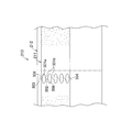
図10を参照すると、これは、図8の工程IVにおける第3加工ウエブ213の一例を示すための第3加工ウエブ213の部分拡大図である。図10における第1カットライン301は、面積の大きい開孔301aを形成している。このような第3加工ウエブ213では、第1カットライン301が単なる直状のものである場合の第3加工ウエブ213と比べて、第1スリット301と301との間の部分である開孔301aと開孔301aとの間の部分301bの幅が狭くなるように変化しているので、第2、第3、第4カットライン312,313,314の長さを短くすることができるようになるとともに、交差方向CDへ大きく離間させることができるようになる。その場合の第3加工ウエブ213および図8の第4加工ウエブ214では、第2、第3、第4カットライン302,303,304によって生じる第2加工ウエブ212の損傷を軽微にすることができる。
図示例のおむつ1においては、弾性部材の使用によって体液吸収性シャーシ11そのものにギャザーが生じるということがなく、また前後胴回り域2,3の中央非弾性域21にギャザーの生じることも確実に防ぐことができるから、おむつ1は図柄24aの視認性がよいものになる。おむつ1において尿が排泄されたことを知らせるためのインジケータを体液吸収性シャーシ11におけるバリヤシート42の内側に取り付けた場合においても、そのインジケータの視認性は良好である。ただし、この発明に係るおむつ1は、図柄入りシート24及び/又はインジケータを使用することのないものでもよく、また、中央非弾性域21と側方弾性域22とが前胴回り域2と後胴回り域3とのいずれか一方にのみ形成されているものであってもよい。
1 おむつ
2 前胴回り域
3 後胴回り域
4 股下域
11 体液吸収性シャーシ
21 中央非弾性域
22 側方弾性域
24a 図柄
32 外層シート
33 内層シート
42 バリヤシート
46 側縁部
201 第1ウエブ
202 第2ウエブ
211 第1加工ウエブ
211a 側縁
211b 側縁
212 第2加工ウエブ
213 第3加工ウエブ
300 カットライン群
301 第1カットライン
302 第2カットライン
303 第3カットライン
306 接合域(塗布域)
307 非塗布域
307a 非塗布域
307b 非塗布域
A 前後方向
B 横方向
C 縦方向
MD 機械方向
CD 交差方向
2 前胴回り域
3 後胴回り域
4 股下域
11 体液吸収性シャーシ
21 中央非弾性域
22 側方弾性域
24a 図柄
32 外層シート
33 内層シート
42 バリヤシート
46 側縁部
201 第1ウエブ
202 第2ウエブ
211 第1加工ウエブ
211a 側縁
211b 側縁
212 第2加工ウエブ
213 第3加工ウエブ
300 カットライン群
301 第1カットライン
302 第2カットライン
303 第3カットライン
306 接合域(塗布域)
307 非塗布域
307a 非塗布域
307b 非塗布域
A 前後方向
B 横方向
C 縦方向
MD 機械方向
CD 交差方向
Claims (13)
- 縦方向と直交する横方向を有し、
前胴回り域と、後胴回り域と、股下域と、前記股下域から前記前後胴回り域それぞれにまで延びる体液吸収性シャーシと、前記前後胴回り域のうちの少なくとも一方の胴回り域において、前記体液吸収性シャーシの両側方それぞれに横方向へ弾性的に伸長可能な側方弾性域と、前記側方弾性域どうしの間に弾性的に伸長することのない中央非弾性域とを含む使い捨てのパンツ型おむつであって、
前記少なくとも一方の胴回り域は、その横方向へ弾性的に伸長することのない外層シートと、前記横方向へ弾性的に伸長可能であって前記外層シートの内面側に位置する内層シートとを含み、前記側方弾性域においては前記内層シートが前記外層シートの内面に伸長状態で接合し、前記中央非弾性域においては、前記内層シートが前記横方向へ二分されていて前記側方弾性域に隣接する域において弾性的に弛緩した状態にあることを特徴とする前記おむつ。 - 前記中央非弾性域が前記体液吸収性シャーシの外側に形成されている請求項1記載のおむつ。
- 前記体液吸収性シャーシが前記おむつの横方向を二等分する中心線の両側に側縁部を有し、前記側縁部が前記側方弾性域に接合している請求項1または2記載のおむつ。
- 前記体液吸収性シャーシがバリヤシートを有し、前記中央非弾性域が前記バリヤシートの外側から前記体液吸収性シャーシに接合している請求項1~3のいずれかに記載のおむつ。
- 前記中央非弾性域と前記体液吸収性シャーシとの間には、前記おむつにおいて尿が排泄されたことを知らせるためのインジケータが介在している請求項1~4のいずれかに記載のおむつ。
- 前記中央非弾性域では、図柄が表わされたシートが前記外層シートの前記内面に接合し、前記外層シートの外側から前記図柄が視認可能である請求項1~5のいずれかに記載のおむつ。
- 前記内層シートは、弾性的に伸長可能な弾性材料と弾性的に伸長することのない非弾性材料とによって形成されている弾性的に伸長可能な弾性繊維不織布である請求項1~6のいずれかに記載のおむつ。
- 前記内層シートが、熱可塑性合成繊維で形成された不織布と、前記横方向へ弾性的に伸長した状態で前記不織布に接合している複数条の糸状ゴムおよび帯状ゴムの一つで形成されている請求項1~6のいずれかに記載のおむつ。
- 前記内層シートが、前記横方向へ弾性的に伸長可能な熱可塑性合成樹脂のフィルムで形成されている請求項1~6のいずれかに記載のおむつ。
- 縦方向と直交する横方向を有し、
前胴回り域と後胴回り域と股下域とを備え、股下域から前記前後胴回り域それぞれへ延びる体液吸収性シャーシと、前記前後胴回り域のうちの少なくとも一方の胴回り域において、前記体液吸収性シャーシの両側方それぞれに前記横方向へ弾性的に伸長可能な側方弾性域と、前記側方弾性域どうしの間に弾性的に伸長することのない中央非弾性域とを含む使い捨てのパンツ型おむつの製造方法であって、
a.機械方向へ弾性的に伸長可能な第1ウエブを機械方向へ伸長状態で連続的に供給する工程と、
b.前記第1ウエブに対して、前記機械方向へ所要の長さを有するとともに前記機械方向に対する交差方向において所要の間隔で並ぶ互いに並行な複数条の第1カットラインによって構成されたカットライン群を形成するとともに、前記カットライン群が前記機械方向において前記おむつの横寸法に相当するピッチで並ぶ前記カットライン群の複数を形成することによって、前記第1ウエブから第1加工ウエブを得る工程と、
c.前記機械方向において弾性的に伸長することのない第2ウエブを前記機械方向へ緊張状態で供給する工程と、
d.前記第2ウエブに対して前記第1加工ウエブを重ねるとともに、隣り合う前記カットライン群どうしの間において前記第1ウエブと前記第2ウエブとが接合状態にある接合域と、前記カットライン群の形成された部位およびそれに隣接する部位とにおいて前記第1加工ウエブと前記第2ウエブとが非接合状態にある非接合域とを形成して、前記第1加工ウエブと前記第2ウエブとから第2加工ウエブを得る工程と、
e.前記第2加工ウエブにおける前記第1加工ウエブの前記カットライン群において、前記交差方向で隣り合う前記第1カットラインそれぞれと交差する第2カットラインと、前記第1加工ウエブにおいて前記機械方向へ延びる両側縁それぞれと前記両側縁それぞれに隣接する前記第1カットラインのそれぞれとに交差する第3カットラインとで形成して、前記第1加工ウエブを前記カットライン群の形成されている域において前記機械方向へ分断して、前記機械方向において該域の両側に位置する第2,第3部位を互いに反対方向へ収縮させて第3加工ウエブを得る工程と、
f.前記第3加工ウエブに前記体液吸収性シャーシの一部分を接合する工程とを含み、
g.前記工程fの後に、前記機械方向における前記接合域の中央で前記第3加工ウエブを分断して、前記第3加工ウエブにおける前記接合域の一部分からは前記側方弾性域を形成し、前記カットライン群が形成されていた域からは前記中央非弾性域を形成する
ことを特徴とする前記製造方法。 - 前記第1ウエブが、弾性的に伸長可能な弾性糸と、弾性的に伸長することのない非弾性糸とによって形成されている弾性的に伸長可能な不織布である請求項10記載の製造方法。
- 前記第1ウエブが、熱可塑性合成繊維で形成された不織布と、前記機械方向へ弾性的に伸長した状態で前記不織布に接合している複数条の糸状ゴムおよび帯状ゴムの一つで形成されている請求項10記載の製造方法。
- 前記第1ウエブが、前記機械方向へ弾性的に伸長可能な熱可塑性合成樹脂のフィルムで形成されている請求項10記載の製造方法。
Priority Applications (3)
| Application Number | Priority Date | Filing Date | Title |
|---|---|---|---|
| EP12742071.9A EP2671551B1 (en) | 2011-02-02 | 2012-01-20 | Disposable pant-type diaper and production method therefor |
| US13/983,349 US9433540B2 (en) | 2011-02-02 | 2012-01-20 | Disposable pull-on diaper having interior elastic sheets and exterior non-elastic sheets |
| CN201280007541.6A CN103347473B (zh) | 2011-02-02 | 2012-01-20 | 一次性内裤型尿布及其制造方法 |
Applications Claiming Priority (2)
| Application Number | Priority Date | Filing Date | Title |
|---|---|---|---|
| JP2011-021250 | 2011-02-02 | ||
| JP2011021250A JP5822476B2 (ja) | 2011-02-02 | 2011-02-02 | 使い捨てのパンツ型おむつおよびその製造方法 |
Publications (1)
| Publication Number | Publication Date |
|---|---|
| WO2012105332A1 true WO2012105332A1 (ja) | 2012-08-09 |
Family
ID=46602551
Family Applications (1)
| Application Number | Title | Priority Date | Filing Date |
|---|---|---|---|
| PCT/JP2012/051153 Ceased WO2012105332A1 (ja) | 2011-02-02 | 2012-01-20 | 使い捨てのパンツ型おむつおよびその製造方法 |
Country Status (5)
| Country | Link |
|---|---|
| US (1) | US9433540B2 (ja) |
| EP (1) | EP2671551B1 (ja) |
| JP (1) | JP5822476B2 (ja) |
| CN (1) | CN103347473B (ja) |
| WO (1) | WO2012105332A1 (ja) |
Cited By (1)
| Publication number | Priority date | Publication date | Assignee | Title |
|---|---|---|---|---|
| WO2013161700A1 (ja) * | 2012-04-25 | 2013-10-31 | 株式会社瑞光 | 使い捨て着用物品およびその製造方法 |
Families Citing this family (12)
| Publication number | Priority date | Publication date | Assignee | Title |
|---|---|---|---|---|
| JP2015515921A (ja) * | 2012-05-15 | 2015-06-04 | ザ プロクター アンド ギャンブルカンパニー | 有利な伸長及び製造性特性を有する使い捨て吸収性パンツ並びに、その製造方法 |
| JP6095305B2 (ja) * | 2012-09-13 | 2017-03-15 | 株式会社瑞光 | 複合収縮部材を用いた着用物品及び該着用物品の製造方法 |
| JP6095211B2 (ja) * | 2012-12-26 | 2017-03-15 | 花王株式会社 | パンツ型吸収性物品及びその製造方法 |
| JP6655288B2 (ja) * | 2014-12-25 | 2020-02-26 | ユニ・チャーム株式会社 | 印刷されたパンツ型の使い捨ておむつ |
| JP6415400B2 (ja) * | 2015-06-26 | 2018-10-31 | ユニ・チャーム株式会社 | 着用物品 |
| JP6719208B2 (ja) * | 2015-12-28 | 2020-07-08 | ユニ・チャーム株式会社 | 複合シートの製造方法 |
| CN108883011B (zh) * | 2016-04-08 | 2021-05-07 | 宝洁公司 | 具有艺术作品的可穿着制品 |
| CN106344277A (zh) * | 2016-08-26 | 2017-01-25 | 芜湖悠派护理用品科技股份有限公司 | 应用于拉拉裤的检测装置 |
| CN106551760A (zh) * | 2016-11-06 | 2017-04-05 | 天津露乐国际贸易有限公司 | 一种婴儿纸尿裤复合芯体的制备方法 |
| JP6968170B2 (ja) * | 2016-12-05 | 2021-11-17 | エシティ・ハイジーン・アンド・ヘルス・アクチエボラグ | 使い捨てパンツ型吸収性物品 |
| GB2572885B (en) * | 2016-12-16 | 2021-10-13 | Kimberly Clark Co | Diaper pants having a partial non-overlapping waist panel structure free of inner material and elastics |
| US10702424B2 (en) | 2017-04-05 | 2020-07-07 | The Procter & Gamble Company | Wearable article having graphics |
Citations (9)
| Publication number | Priority date | Publication date | Assignee | Title |
|---|---|---|---|---|
| JPH06197925A (ja) * | 1991-01-28 | 1994-07-19 | Uni Charm Corp | 使い捨てパンツの製造方法 |
| JPH06254117A (ja) * | 1993-03-08 | 1994-09-13 | Toyo Eizai Kk | 弾性体の切断方法及び切断装置 |
| JPH0677721U (ja) * | 1993-04-22 | 1994-11-01 | 新王子製紙株式会社 | 使いすておむつ |
| JP2001000478A (ja) * | 1999-06-16 | 2001-01-09 | Zuiko Corp | 使い捨てパンツ及びその製造方法 |
| JP2001145666A (ja) | 1999-11-19 | 2001-05-29 | Kao Corp | 吸収性物品 |
| JP2001286504A (ja) | 2001-02-27 | 2001-10-16 | Kao Corp | 吸収性物品の製造方法 |
| JP2002505913A (ja) * | 1998-03-12 | 2002-02-26 | ザ、プロクター、エンド、ギャンブル、カンパニー | 連続した弾性腰バンドを有する使い捨て吸収性下着 |
| JP2008148943A (ja) * | 2006-12-18 | 2008-07-03 | Livedo Corporation | 使い捨ておむつの製造方法 |
| JP2010233733A (ja) * | 2009-03-30 | 2010-10-21 | Uni Charm Corp | 使い捨ておむつ |
Family Cites Families (8)
| Publication number | Priority date | Publication date | Assignee | Title |
|---|---|---|---|---|
| JP3459434B2 (ja) | 1992-08-26 | 2003-10-20 | 京セラ株式会社 | アンテナ |
| US7118558B2 (en) * | 2001-11-06 | 2006-10-10 | Tyco Healthcare Retail Services Ag | Cloth-like laminate and absorbent garment |
| US7332642B2 (en) * | 2004-04-19 | 2008-02-19 | The Procter & Gamble Company | Disposable absorbent articles having printed wetness indicators |
| US8475424B2 (en) * | 2006-06-13 | 2013-07-02 | The Procter & Gamble Company | Disposable pull-on garment |
| WO2008041639A1 (en) * | 2006-09-29 | 2008-04-10 | Daio Paper Corporation | Paper diaper, method of forming stretchable section of absorbent article, and device for forming the stretchable section |
| JP5405761B2 (ja) * | 2008-03-27 | 2014-02-05 | ユニ・チャーム株式会社 | 着用物品 |
| JP5383122B2 (ja) * | 2008-09-01 | 2014-01-08 | ユニ・チャーム株式会社 | 使い捨ておむつ |
| JP5592168B2 (ja) * | 2009-08-31 | 2014-09-17 | ユニ・チャーム株式会社 | 使い捨て着用物品 |
-
2011
- 2011-02-02 JP JP2011021250A patent/JP5822476B2/ja active Active
-
2012
- 2012-01-20 WO PCT/JP2012/051153 patent/WO2012105332A1/ja not_active Ceased
- 2012-01-20 US US13/983,349 patent/US9433540B2/en active Active
- 2012-01-20 EP EP12742071.9A patent/EP2671551B1/en not_active Not-in-force
- 2012-01-20 CN CN201280007541.6A patent/CN103347473B/zh active Active
Patent Citations (9)
| Publication number | Priority date | Publication date | Assignee | Title |
|---|---|---|---|---|
| JPH06197925A (ja) * | 1991-01-28 | 1994-07-19 | Uni Charm Corp | 使い捨てパンツの製造方法 |
| JPH06254117A (ja) * | 1993-03-08 | 1994-09-13 | Toyo Eizai Kk | 弾性体の切断方法及び切断装置 |
| JPH0677721U (ja) * | 1993-04-22 | 1994-11-01 | 新王子製紙株式会社 | 使いすておむつ |
| JP2002505913A (ja) * | 1998-03-12 | 2002-02-26 | ザ、プロクター、エンド、ギャンブル、カンパニー | 連続した弾性腰バンドを有する使い捨て吸収性下着 |
| JP2001000478A (ja) * | 1999-06-16 | 2001-01-09 | Zuiko Corp | 使い捨てパンツ及びその製造方法 |
| JP2001145666A (ja) | 1999-11-19 | 2001-05-29 | Kao Corp | 吸収性物品 |
| JP2001286504A (ja) | 2001-02-27 | 2001-10-16 | Kao Corp | 吸収性物品の製造方法 |
| JP2008148943A (ja) * | 2006-12-18 | 2008-07-03 | Livedo Corporation | 使い捨ておむつの製造方法 |
| JP2010233733A (ja) * | 2009-03-30 | 2010-10-21 | Uni Charm Corp | 使い捨ておむつ |
Cited By (2)
| Publication number | Priority date | Publication date | Assignee | Title |
|---|---|---|---|---|
| WO2013161700A1 (ja) * | 2012-04-25 | 2013-10-31 | 株式会社瑞光 | 使い捨て着用物品およびその製造方法 |
| JPWO2013161700A1 (ja) * | 2012-04-25 | 2015-12-24 | 株式会社瑞光 | 使い捨て着用物品およびその製造方法 |
Also Published As
| Publication number | Publication date |
|---|---|
| US20130317468A1 (en) | 2013-11-28 |
| JP2012157661A (ja) | 2012-08-23 |
| EP2671551A4 (en) | 2017-03-29 |
| EP2671551B1 (en) | 2018-05-30 |
| US9433540B2 (en) | 2016-09-06 |
| CN103347473B (zh) | 2015-04-08 |
| CN103347473A (zh) | 2013-10-09 |
| EP2671551A1 (en) | 2013-12-11 |
| JP5822476B2 (ja) | 2015-11-24 |
Similar Documents
| Publication | Publication Date | Title |
|---|---|---|
| JP5822476B2 (ja) | 使い捨てのパンツ型おむつおよびその製造方法 | |
| CN106132370B (zh) | 吸收性物品 | |
| TWI584793B (zh) | Dispose of items with disposable dessert | |
| CN102427791B (zh) | 短裤型吸收性物品 | |
| JP5303689B1 (ja) | 使い捨て着用物品 | |
| JP6005000B2 (ja) | 使い捨て着用物品 | |
| CN206642003U (zh) | 短裤型吸收性物品 | |
| JP6200781B2 (ja) | パンツ型着用物品 | |
| JP5346176B2 (ja) | パンツ形状の着用物品およびその製造方法 | |
| JP5385187B2 (ja) | 使い捨ての着用物品 | |
| WO2015025760A1 (ja) | 使い捨ておむつの製造方法および使い捨ておむつ | |
| JP6230351B2 (ja) | 使い捨て着用物品 | |
| JP2008228760A (ja) | パンツ型吸収性物品の製造方法 | |
| CN109982672B (zh) | 吸收性物品 | |
| JP5530196B2 (ja) | 使い捨てのパンツ型着用物品 | |
| JP5270143B2 (ja) | 使い捨てのパンツ型着用物品およびその製造方法 | |
| JP6072555B2 (ja) | 使い捨てのおむつ | |
| WO2013018791A1 (ja) | 使い捨て着用物品 | |
| JP7699232B2 (ja) | パンツ型物品を生産する方法 | |
| WO2010134587A1 (ja) | 吸収性物品 | |
| JP4535980B2 (ja) | パンツ型使い捨ておむつ | |
| JP6431761B2 (ja) | 使い捨て着用物品 | |
| JP2007260148A (ja) | パンツ型吸収性物品及びその製造方法 | |
| JP7173829B2 (ja) | パンツ型吸収性物品 | |
| WO2018123489A1 (ja) | 吸収性物品 |
Legal Events
| Date | Code | Title | Description |
|---|---|---|---|
| 121 | Ep: the epo has been informed by wipo that ep was designated in this application |
Ref document number: 12742071 Country of ref document: EP Kind code of ref document: A1 |
|
| WWE | Wipo information: entry into national phase |
Ref document number: 2012742071 Country of ref document: EP |
|
| NENP | Non-entry into the national phase |
Ref country code: DE |
|
| WWE | Wipo information: entry into national phase |
Ref document number: 1301004289 Country of ref document: TH Ref document number: 13983349 Country of ref document: US |