WO2012105421A1 - Dispositif pour transporter une structure en nid d'abeille et procédé pour étanchéifier une structure en nid d'abeille - Google Patents
Dispositif pour transporter une structure en nid d'abeille et procédé pour étanchéifier une structure en nid d'abeille Download PDFInfo
- Publication number
- WO2012105421A1 WO2012105421A1 PCT/JP2012/051723 JP2012051723W WO2012105421A1 WO 2012105421 A1 WO2012105421 A1 WO 2012105421A1 JP 2012051723 W JP2012051723 W JP 2012051723W WO 2012105421 A1 WO2012105421 A1 WO 2012105421A1
- Authority
- WO
- WIPO (PCT)
- Prior art keywords
- honeycomb structure
- rotation angle
- hand
- axis
- sealing
- Prior art date
- Legal status (The legal status is an assumption and is not a legal conclusion. Google has not performed a legal analysis and makes no representation as to the accuracy of the status listed.)
- Ceased
Links
Images

Classifications
-
- B—PERFORMING OPERATIONS; TRANSPORTING
- B25—HAND TOOLS; PORTABLE POWER-DRIVEN TOOLS; MANIPULATORS
- B25J—MANIPULATORS; CHAMBERS PROVIDED WITH MANIPULATION DEVICES
- B25J9/00—Program-controlled manipulators
- B25J9/0093—Program-controlled manipulators co-operating with conveyor means
-
- B—PERFORMING OPERATIONS; TRANSPORTING
- B25—HAND TOOLS; PORTABLE POWER-DRIVEN TOOLS; MANIPULATORS
- B25J—MANIPULATORS; CHAMBERS PROVIDED WITH MANIPULATION DEVICES
- B25J9/00—Program-controlled manipulators
- B25J9/02—Program-controlled manipulators characterised by movement of the arms, e.g. cartesian coordinate type
- B25J9/023—Cartesian coordinate type
-
- B—PERFORMING OPERATIONS; TRANSPORTING
- B28—WORKING CEMENT, CLAY, OR STONE
- B28B—SHAPING CLAY OR OTHER CERAMIC COMPOSITIONS; SHAPING SLAG; SHAPING MIXTURES CONTAINING CEMENTITIOUS MATERIAL, e.g. PLASTER
- B28B11/00—Apparatus or processes for treating or working the shaped or preshaped articles
- B28B11/003—Apparatus or processes for treating or working the shaped or preshaped articles the shaping of preshaped articles, e.g. by bending
- B28B11/006—Making hollow articles or partly closed articles
- B28B11/007—Using a mask for plugging
-
- B—PERFORMING OPERATIONS; TRANSPORTING
- B28—WORKING CEMENT, CLAY, OR STONE
- B28B—SHAPING CLAY OR OTHER CERAMIC COMPOSITIONS; SHAPING SLAG; SHAPING MIXTURES CONTAINING CEMENTITIOUS MATERIAL, e.g. PLASTER
- B28B17/00—Details of, or accessories for, apparatus for shaping the material; Auxiliary measures taken in connection with such shaping
- B28B17/0063—Control arrangements
Definitions
- One embodiment of the present invention relates to a honeycomb structure transport device and a honeycomb structure sealing method.
- honeycomb filters are widely known for DPF (Diesel particulate filter) use.
- This honeycomb filter has a structure in which one end side of some through holes of a honeycomb structure having a large number of through holes is sealed with a sealing material, and the other end side of the remaining through holes is sealed with a sealing material.
- Patent Document 1 discloses a method for manufacturing such a honeycomb filter.
- a honeycomb structure is pressed against a through hole by a piston through a sealing mask having a through hole at a sealing position with respect to one end face of the honeycomb structure disposed in a cylinder.
- the sealing material is supplied to the end of the desired through hole.
- the diameter of the through hole of the honeycomb structure is small.
- the diameter of the through hole of the sealing mask is approximately the same as the through hole of the honeycomb structure. Therefore, in a state where the through holes of the honeycomb structure and the through holes of the mask are correctly overlapped, it is difficult to see the outline of the outer wall of the honeycomb structure and the outline of the through holes from the opening of the sealing mask. Therefore, accurate alignment of the through holes of the honeycomb structure and the through holes of the sealing mask has been very difficult.
- One embodiment of the present invention has been made in view of the above problems, and transport of a honeycomb structure capable of easily performing accurate alignment between the through hole of the honeycomb structure and the through hole of the sealing mask.
- An object is to provide a device and a method for sealing a honeycomb structure.
- One embodiment of the present invention includes a hand that can hold a columnar honeycomb structure arranged in a vertical direction, and a first axis drive unit that moves the hand along a first axis rail extending in a first horizontal direction
- a second axis drive unit that translates the first axis rail along a second axis rail extending in a second horizontal direction different from the first horizontal direction, and a vertical axis for the hand relative to the first axis rail
- a hand rotation unit that rotates around, a camera that captures the end face of the honeycomb structure gripped by the hand at the reference position, and an initial rotation angle around the vertical axis of the honeycomb structure at the reference position is recognized based on the camera image
- An initial rotation angle recognizing unit that drives the first axis driving unit and the second axis driving unit, and an axis driving control unit that conveys the honeycomb structure gripped by the hand from the reference position to the sealing mask;
- a required rotation angle acquisition unit for acquiring a rotation angle necessary for setting the
- the initial rotation angle recognition unit recognizes the initial rotation angle around the vertical axis of the honeycomb structure at the reference position, and the necessary rotation angle acquisition unit based on the initial rotation angle recognized at the reference position, Obtain a rotation angle necessary for setting the rotation angle of the honeycomb structure with respect to the sealing mask to a desired final rotation angle, and drive the hand rotation unit based on the necessary rotation angle acquired by the necessary rotation angle acquisition unit. Rotate the honeycomb structure.
- the honeycomb structure held by the hand can be arranged on the sealing mask at a desired rotation angle, so that the sealing mask and the honeycomb structure can be easily aligned.
- the second axis rail can be orthogonal to the first axis rail.
- the second axis rail is orthogonal to the first axis rail.
- the camera can photograph the lower end surface of the honeycomb structure.
- the camera photographs the lower end surface of the honeycomb structure.
- the end face can be easily photographed while the honeycomb structure is held by the hand, so that the angle detection accuracy and the alignment accuracy are higher than when the image is released from the hand and then taken again by the hand. .
- One embodiment of the present invention includes a step of holding a columnar honeycomb structure arranged in a vertical direction with a hand, a step of taking an image of an end face of the honeycomb structure held by the hand, and an image based on the image.
- a step of obtaining a rotation angle necessary for setting the rotation angle of the honeycomb structure on the sealing mask to the desired final rotation angle based on the initial rotation angle recognized in The step of rotating the hand based on the rotation angle, the step of placing the honeycomb structure on the sealing mask after the rotation of the hand on the sealing mask, and the honeycomb structure via the placed sealing mask A method for sealing a honeycomb structure including a step of supplying a sealing material.
- honeycomb structure transport device and the honeycomb structure sealing method of the embodiment of the present invention it is possible to easily perform accurate alignment between the through holes of the honeycomb structure and the through holes of the sealing mask. it can.
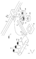
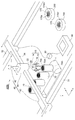
- FIG. 2 is a perspective view subsequent to FIG. 1 illustrating the operation of the conveying device according to the first embodiment of the present invention during sealing of the honeycomb structure.
- FIG. 6 is a perspective view subsequent to FIG. 5 illustrating the operation of the conveying device according to the first embodiment of the present invention during sealing of the honeycomb structure. It is a perspective view which shows the conveying apparatus, feed apparatus, and sealing apparatus which concern on 2nd Embodiment of this invention.
- honeycomb structure 70 to be conveyed will be described.
- the honeycomb structure 70 is a column having a large number of through holes 70a extending in the vertical direction and opening at both upper and lower end faces.
- the outer shape of the honeycomb structure 70 is not particularly limited.
- a cylindrical column, an elliptical column, a rectangular column for example, a regular polygonal column such as a regular triangular column, a square column, a regular hexagonal column, a regular octagonal column, or a triangular prism other than a regular polygonal column
- a quadrangular prism, a hexagonal prism, an octagonal prism, etc. A quadrangular prism, a hexagonal prism, an octagonal prism, etc.
- each through-hole 70a is not specifically limited, For example, polygons, such as a circle, an ellipse, a square, a rectangle, a triangle, a hexagon, etc. are mentioned.
- the through holes 70a may have different diameters and different cross-sectional shapes.
- the arrangement form of the through holes 70a when viewed from the upper and lower end faces of the honeycomb structure 70 is not particularly limited.
- the squares are arranged such that the central axis of the through holes 70a is located at the apexes of the squares.
- the diameter of the through hole 70a is not particularly limited.
- the cross section when the cross section is a square, it can be 0.8 to 2.5 mm on a side.
- the thickness of the partition wall separating the through holes 70a can be set to 0.15 to 0.76 mm, for example.
- the length in the direction in which the through hole 70a of the honeycomb structure 70 extends is not particularly limited, but may be, for example, 40 to 350 mm.
- the outer diameter of the honeycomb structure 70 is not particularly limited, but may be, for example, 100 to 320 mm.
- the honeycomb structure 70 can be green (unfired body) that becomes porous ceramics by firing.
- the honeycomb structure 70 can be a formed body containing a ceramic raw material or a formed body of ceramic particles.
- the ceramic is not particularly limited, and examples thereof include alumina, silica, mullite, cordierite, glass, oxides such as aluminum titanate, silicon carbide, silicon nitride, and metal.
- the aluminum titanate can further contain magnesium and / or silicon.
- the honeycomb structure 70 may be a sintered ceramic.
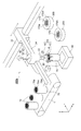
- the transport device 400 a is provided adjacent to the feed device 1 and the sealing device 200.
- the feed device 1 feeds the honeycomb structure 70 to the transport device 400a.
- the transport device 400a places the honeycomb structure 70 fed by the feed device 1 on the sealing mask 170 of the sealing device 200 at a predetermined rotation angle.
- the sealing device 200 supplies a sealing material to one end face of the honeycomb structure 70.
- two sealing devices 200 are provided side by side around the transport device 400a.
- the transfer apparatus 400a of this embodiment is a robot transfer system.
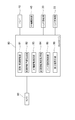
- the transport apparatus 400a mainly includes a hand 10, an X-axis rail 32, a Y-axis rail 34, an XY-axis drive unit 40, a hand rotation unit 20, a hand lifting unit 22, a camera 90, and a controller 80.
- the hand 10 includes a base portion 14 and a holding member 12 fixed to the base portion 14 and capable of holding the honeycomb structure 70.
- the holding member 12 holds the columnar honeycomb structure 70 arranged along the vertical direction while holding the direction.
- the gripping member 12 can sandwich the upper part of the side surface of the honeycomb structure 70 with a plurality of finger members.
- a vertical rotation shaft 16 is connected to the hand 10.
- a Y-axis drive unit 44 that moves the hand 10 along a Y-axis rail 34 that extends horizontally in the Y-axis direction in the drawing, and an X-axis rail 32 that extends horizontally in the X-axis direction in the drawing orthogonal to the Y-axis direction.
- An X-axis drive unit 42 that translates the Y-axis rail 34 is provided.
- the hand 10 is fixed to the Y-axis drive unit 44 via a hand rotation unit 20 that rotates the hand 10 around the vertical rotation axis 16 with respect to the Y-axis drive unit 44.
- the X axis drive unit 42 and the Y axis drive unit 44 constitute the XY axis drive unit 40.
- the vertical rotary shaft 16 is further provided with a hand elevating unit 22 that moves the vertical rotary shaft 16 in the vertical direction.
- the camera 90 is disposed at a position where the end face and the lower end face of the hand 10 holding the honeycomb structure 70 can be photographed.
- the controller 80 is connected to the hand 10, the XY axis driving unit 40, the hand rotating unit 20, the hand elevating unit 22, and the camera 90.
- the controller 80 is usually composed of a computer and can exhibit the following functions.
- the gripping / initial movement unit 81 drives the XY axis driving unit 40 and the hand 10 to grip the honeycomb structure 70 fed by the feed device 1, and a position above the camera 90 (hereinafter referred to as a reference position).
- the honeycomb structure 70 is conveyed until there is).
- the initial rotation angle recognizing unit 82 captures the end face of the honeycomb structure 70 with the camera 90 and, based on the image captured by the camera 90, the honeycomb structure gripped by the hand 10 at the reference position where the image is captured.
- the initial rotation angle ⁇ around 70 vertical axes is recognized.
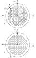
- the rotation angle is an angle indicating how much the honeycomb structure 70 is rotated around the rotation center with respect to the reference rotation state around the vertical axis.
- the state of FIG. 3A is a rotation state that serves as a reference for the honeycomb structure 70.
- a mark 70m (or orientation flat) may be provided on the periphery of the honeycomb structure 70.
- the reference rotation state is a state in which the mark 70m is on the X axis passing through the rotation center O.
- the rotation angle ⁇ is defined as the angle formed by the X axis and the straight line connecting the center O and the position B. can do.
- the initial rotation angle ⁇ is a rotation angle at a reference position on the camera 90.
- the method for recognizing the initial rotation angle based on the image of the camera 90 may be a known image processing method, and is not particularly limited.
- a mark 70m is provided in advance on, for example, the peripheral portion of the end face of the honeycomb structure 70, the mark 70m and the rotation center O are extracted from the image, a line connecting the mark 70m and the rotation center O, and a reference direction
- the initial rotation angle ⁇ with respect to a predetermined reference state can be acquired based on the angle formed with the X axis.
- the mark 70n may be provided on the opposite side of the mark 70m across the rotation center O, and the initial rotation angle ⁇ may be obtained based on the angle formed by the line connecting the marks 70m and 70n and the reference direction.
- the initial rotation angle ⁇ can be obtained.
- the outer shape of the honeycomb structure 70 is a non-circular shape such as a rectangle
- an outline is extracted by image processing, and the initial rotation angle ⁇ can be obtained based on a line connecting the vertices. It is also possible to recognize the direction in which the through holes 70a of the honeycomb structure 70 are arranged by image processing, and to recognize the initial rotation angle ⁇ of the honeycomb structure 70 from the angle formed by the direction and the X axis.
- the XY axis drive control unit 83 drives the XY axis drive unit 40 to convey the honeycomb structure 70 gripped by the hand 10 from the reference position (on the camera) to the top of the sealing mask 170.
- the position of the X-axis drive unit 42 on the X-axis rail 32 and the Y-axis drive are determined according to this positional relationship.
- By appropriately determining the position of the portion 44 on the Y-axis rail 34, such conveyance is easy. That is, it is easy to match the positions in the XY direction other than the rotation angle between the honeycomb structure 70 and the sealing mask 170.
- the necessary rotation angle acquisition unit 84 acquires a rotation angle necessary for setting the final rotation angle of the honeycomb structure on the sealing mask 170 to a desired rotation angle based on the initial rotation angle ⁇ recognized at the reference position. To do.
- the sealing mask 170 has a mark 170 m in the peripheral portion, and the honeycomb structure is formed on the sealing mask 170 so that the mark 170 m matches the mark 70 m of the honeycomb structure 70. It is assumed that the final rotation angle of the body 70 must be matched. The same rotation angle as that of the honeycomb structure 70 can be defined for the sealing mask 170. Here, it is assumed that the rotation angle of the sealing mask 170 set in the sealing device 200 is ⁇ . In this case, the final rotation angle to be taken by the honeycomb structure 70 is ⁇ .
- the initial rotation angle of the honeycomb structure 70 at the reference position on the camera 90 is ⁇ .
- ⁇ The initial rotation angle of the honeycomb structure 70 at the reference position on the camera 90.
- the hand rotation control unit 85 rotates the honeycomb structure 70 by driving the hand rotation unit 20 based on the necessary rotation angle ⁇ described above.
- the post-process instruction unit 86 drives the hand lifting unit 22 and the hand 10 to lower the honeycomb structure 70 on the sealing mask 170 onto the sealing mask 170. Further, it is released from the hand 10 and placed on the sealing mask 170.
- the honeycomb structure 70 may be held without being released from the hand 10.
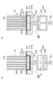
- the sealing device 200 mainly includes a main body 210, an elastic plate 220, and a pump 250.
- the main body 210 is a rigid member formed of a metal (for example, stainless steel) or a polymer material (for example, fiber reinforced plastic).
- a recess 210d is formed in the main body 210, and a porous member 210p is attached to the inner surface of the recess 210d.
- the elastic plate 220 is disposed on the main body 210 so as to cover the opening surface of the recess 210d.
- the elastic plate 220 has elasticity and can be easily deformed.
- the elastic plate 220 can be a rubber plate.
- the elastic plate 220 is fixed to the main body 210 by a ring member 225.
- the ring member 225 has an opening 225a at a position corresponding to the recess 210d of the main body 210, thereby forming an annular shape.
- the ring member 225 is arrange
- the main body 210 further has a communication path 210e communicating with the porous member 210p on the bottom surface of the recess 210d.
- a pump 250 is connected to the communication path 210e.
- the pump 250 includes a cylinder 251 and a piston 253 disposed in the cylinder 251.
- a motor 255 that reciprocates the piston 253 in the axial direction is connected to the piston 253.
- a closed space V formed by the main body 210, the communication path 210 e, and the cylinder 251 is formed between the elastic plate 220 and the piston 253, and a gas is contained in the closed space V.
- a fluid FL such as a liquid is filled.
- the fluid FL can be discharged from the recess 210d of the main body 210, and the elastic plate 220 can be brought into close contact with the inner surface of the recess 210d to form the recess 220d by the elastic plate 220 (FIG. 4 (a)), and the elastic plate 220 can be pulled away from the bottom of the recess 210d (state (b) of FIG. 4) to supply the fluid FL into the recess 210d.
- the piston 253 is lowered to form a recess 220d by the elastic plate 220, and the sealing paste P is stored in the recess 220d.
- a sealing mask 170 is disposed on the recess 210 d of the main body 210.
- the hole 170a of the sealing mask 170 needs to be positioned with respect to the honeycomb structure 70 so as to face only the hole to be sealed among the through holes 70a of the ceramic honeycomb structure 70.
- the sealing mask 170 has a mark 170m on the outer peripheral portion.
- the mark 170m is, for example, an orientation flat.
- the honeycomb structure 70 is transported to the vicinity of the transport device 400 a by the feed device 1. At this time, the rotation angles in the transported honeycomb structure 70 are usually uneven.
- the XY axis driving unit 40 and the hand 10 are driven by the instruction of the gripping / initial moving unit 81 of the controller 80 to grip the honeycomb structure 70 with the hand 10, and then on the camera 90 as shown in FIG. Transport to.
- the camera 90 images the end face of the honeycomb structure 70.
- the initial rotation angle recognition unit 82 of the controller 80 determines the initial rotation angle ⁇ around the vertical axis of the honeycomb structure 70 held by the hand 10 at the reference position where the image is taken based on the image of the camera 90. recognize.
- the XY axis drive control unit 83 of the controller 80 drives the XY axis drive unit 40 to seal the honeycomb structure 70 gripped by the hand 10 from the reference position on the camera 90. It is conveyed to the top of the mask 170 for use.
- the sealing device 200 since there are a plurality of sealing devices 200, the sealing device 200 may be appropriately transported onto the sealing mask 170 of the sealing device 200 that has been prepared.
- the hand rotation control unit 85 drives the hand rotation unit 20 based on the necessary rotation angle ⁇ described above to rotate the honeycomb structure 70. Thereby, the rotation angle of the honeycomb structure 70 becomes ⁇ on the sealing mask 170, and the alignment of the rotation angle with the sealing mask 170 is completed.
- the post-process instruction unit 86 drives the hand elevating unit 22 and the hand 10 to lower the honeycomb structure 70 on the sealing mask 170 onto the sealing mask, and further releases from the hand 10 for sealing. It is placed on the mask 170 (the state shown in FIG. 4A). The honeycomb structure 70 may be held without being released from the hand 10.
- the fluid FL is supplied into the recess 210d by moving the piston 253 of the pump 250 upward, thereby moving the elastic plate 220 toward the mask 170.
- the sealing paste P is supplied into a part of the through-holes 70 a of the ceramic honeycomb structure 70 through the through-holes 170 a of the mask 170, thereby forming the sealing portions 72.
- the piston 253 is further raised to further supply the fluid FL between the elastic plate 220 and the main body 210, and the elastic plate 220 is deformed in a convex shape upward, thereby forming a ceramic honeycomb structure.
- the body 70 and the mask 170 are separated from the elastic plate 220.
- the direction of the honeycomb structure is inverted upside down by a reversing device (not shown), and the same operation is performed (if the initial rotation angle is constant, shooting and recognition of the initial rotation angle are not necessary. ),
- the honeycomb structure 70 can be placed on the other sealing portion 200, and the same sealing can be performed on the other surface of the ceramic honeycomb structure 70.
- a ceramic honeycomb filter can be manufactured by drying and firing the sealed ceramic honeycomb structure. Such a ceramic honeycomb filter can be used as, for example, a diesel particulate filter.
- sealing masks 170 of different types and forms, and by providing a replacement device (not shown) for the sealing mask 170, two or more types of honeycomb structures can be sequentially sealed by this device. it can.
- the initial rotation angle recognition unit 82 of the controller 80 recognizes the initial rotation angle around the vertical axis of the honeycomb structure 70 at the reference position, and the necessary rotation angle acquisition unit 84 recognizes at the reference position. Based on the initial rotation angle, a rotation angle necessary for setting the rotation angle of the honeycomb structure 70 with respect to the sealing mask 170 to a desired final rotation angle is acquired, and the necessary rotation angle acquired by the necessary rotation angle acquisition unit 84 Based on the above, the hand rotating unit 20 is driven to rotate the honeycomb structure 70. As a result, when the honeycomb structure 70 having irregular rotation angles in advance is transferred onto the sealing mask 170, the honeycomb structure 70 held by the hand 10 is arranged on the sealing mask 170 as a desired rotation angle. Therefore, the sealing mask 170 and the honeycomb structure 70 can be easily aligned.
- the Y-axis drive unit 44 that moves the hand 10 along the Y-axis rail 32 and the X-axis drive unit 42 that translates the Y-axis rail 32 along the X-axis rail 34 are provided, it is simple. Since the honeycomb structure 70 gripped by the hand 10 can be moved in parallel without changing the rotation angle, the control of the conveying device 400a is facilitated.
- the Y-axis rail 34 is orthogonal to the X-axis rail 32.
- the X-axis drive part 42 and the Y-axis drive part 44 can each move the honeycomb structure 70 to a predetermined position with a minimum movement distance.
- the camera 90 photographs the lower end surface of the honeycomb structure 70.
- the angle detection accuracy and the position alignment can be performed as compared with the case where the image is released from the hand 10 and is taken again by the hand 10. Increases accuracy.
- this invention is not limited to the said embodiment, A various deformation
- another X-axis rail 33 is arranged in addition to the X-axis rail 32, and the Y-axis rail 34 is connected to the X-axis rail 32,
- the Y-axis rail is arranged so as to straddle 33, and is translated by the X-axis drive unit 42 that slides along the X-axis rail 32 and the X-axis drive unit 43 that slides along the X-axis rail 33.
- the camera 90 is disposed at a position away from the feed device 1, but the position where the bottom surface of the feed device 1 is transparent and the honeycomb structure 70 is gripped from the feed device 1 by the hand 10. You can also shoot.
- the timing of the rotation of the hand 10 based on the rotation angle ⁇ by the hand rotating unit 20 is after the honeycomb structure 70 is conveyed onto the sealing mask 170, but is not limited thereto. For example, it may be during the transfer from the reference position to the top of the sealing mask 170, or may be during the transfer to the reference position before the transfer, and may be rotated over a plurality of these periods. You may let them.
- the honeycomb structure transport apparatus and the honeycomb structure sealing method of the embodiment of the present invention accurate alignment between the through holes of the honeycomb structure and the through holes of the sealing mask is facilitated. Can be done.
Landscapes
- Engineering & Computer Science (AREA)
- Mechanical Engineering (AREA)
- Chemical & Material Sciences (AREA)
- Ceramic Engineering (AREA)
- Robotics (AREA)
- Structural Engineering (AREA)
- Filtering Materials (AREA)
- Devices For Post-Treatments, Processing, Supply, Discharge, And Other Processes (AREA)
- Manipulator (AREA)
Abstract
Selon l'invention, une unité de reconnaissance d'angle de rotation initial d'un contrôleur reconnaît un angle de rotation initial autour de l'axe vertical d'une structure en nid d'abeille, une unité d'acquisition d'angle de rotation requis acquiert, sur la base de l'angle de rotation initial reconnu, l'angle de rotation requis nécessaire pour modifier l'angle de rotation de la structure en nid d'abeille par rapport à un masque d'étanchéité jusqu'à l'obtention d'un angle de rotation voulu, et une unité de rotation de préhenseur en forme de main est entraînée en fonction de l'angle de rotation requis obtenu par l'unité d'acquisition d'angle de rotation requis, ce qui met en rotation la structure en nid d'abeille. Même lorsque les structures en nid d'abeille sont transportées avec des angles de rotation non uniformes, il est facile d'aligner les masques d'étanchéité et les structures en nid d'abeille, puisque les structures en nid d'abeille peuvent être agencées sur les masques d'étanchéité à un angle de rotation voulu.
Applications Claiming Priority (2)
| Application Number | Priority Date | Filing Date | Title |
|---|---|---|---|
| JP2011022965A JP5054830B2 (ja) | 2011-02-04 | 2011-02-04 | ハニカム構造体の搬送装置、及び、ハニカム構造体の封口方法 |
| JP2011-022965 | 2011-02-04 |
Publications (1)
| Publication Number | Publication Date |
|---|---|
| WO2012105421A1 true WO2012105421A1 (fr) | 2012-08-09 |
Family
ID=46602638
Family Applications (1)
| Application Number | Title | Priority Date | Filing Date |
|---|---|---|---|
| PCT/JP2012/051723 Ceased WO2012105421A1 (fr) | 2011-02-04 | 2012-01-26 | Dispositif pour transporter une structure en nid d'abeille et procédé pour étanchéifier une structure en nid d'abeille |
Country Status (2)
| Country | Link |
|---|---|
| JP (1) | JP5054830B2 (fr) |
| WO (1) | WO2012105421A1 (fr) |
Cited By (4)
| Publication number | Priority date | Publication date | Assignee | Title |
|---|---|---|---|---|
| EP2537655A4 (fr) * | 2010-12-07 | 2013-09-04 | Sumitomo Chemical Co | Dispositif pour transporter un corps structural en nid-d'abeilles, procédé pour l'étanchéité d'un corps structural en nid-d'abeilles et procédé de production d'un corps structural en nid-d'abeilles |
| EP2982474A3 (fr) * | 2014-08-08 | 2016-03-02 | Murata Machinery, Ltd. | Dispositif de transport de pièce et machine-outil |
| CN106625626A (zh) * | 2016-10-27 | 2017-05-10 | 宁波三星医疗电气股份有限公司 | 一种电能表搬运机械手及电能表搬运方法 |
| CN109759882A (zh) * | 2019-01-17 | 2019-05-17 | 浙江俊博汽车部件有限公司 | 一种汽车离合器加工机床用机械手装置 |
Families Citing this family (1)
| Publication number | Priority date | Publication date | Assignee | Title |
|---|---|---|---|---|
| JP7115844B2 (ja) | 2017-12-13 | 2022-08-09 | 日本碍子株式会社 | 柱状ハニカム構造体の移載装置 |
Citations (4)
| Publication number | Priority date | Publication date | Assignee | Title |
|---|---|---|---|---|
| JPH0445652U (fr) * | 1990-08-22 | 1992-04-17 | ||
| JP2002018759A (ja) * | 2000-07-12 | 2002-01-22 | Ngk Insulators Ltd | セラミックス柱状体用移載装置及び移載方法 |
| JP2008055347A (ja) * | 2006-08-31 | 2008-03-13 | Denso Corp | セラミックハニカム構造体の栓詰め方法 |
| JP2009006628A (ja) * | 2007-06-29 | 2009-01-15 | Ngk Insulators Ltd | ハニカム構造体の目封止用マスク、目封止装置、目封止方法、及び製造方法 |
-
2011
- 2011-02-04 JP JP2011022965A patent/JP5054830B2/ja not_active Expired - Fee Related
-
2012
- 2012-01-26 WO PCT/JP2012/051723 patent/WO2012105421A1/fr not_active Ceased
Patent Citations (4)
| Publication number | Priority date | Publication date | Assignee | Title |
|---|---|---|---|---|
| JPH0445652U (fr) * | 1990-08-22 | 1992-04-17 | ||
| JP2002018759A (ja) * | 2000-07-12 | 2002-01-22 | Ngk Insulators Ltd | セラミックス柱状体用移載装置及び移載方法 |
| JP2008055347A (ja) * | 2006-08-31 | 2008-03-13 | Denso Corp | セラミックハニカム構造体の栓詰め方法 |
| JP2009006628A (ja) * | 2007-06-29 | 2009-01-15 | Ngk Insulators Ltd | ハニカム構造体の目封止用マスク、目封止装置、目封止方法、及び製造方法 |
Cited By (7)
| Publication number | Priority date | Publication date | Assignee | Title |
|---|---|---|---|---|
| EP2537655A4 (fr) * | 2010-12-07 | 2013-09-04 | Sumitomo Chemical Co | Dispositif pour transporter un corps structural en nid-d'abeilles, procédé pour l'étanchéité d'un corps structural en nid-d'abeilles et procédé de production d'un corps structural en nid-d'abeilles |
| US8863685B2 (en) | 2010-12-07 | 2014-10-21 | Sumitomo Chemical Company, Limited | Device for conveying honeycomb structural body, method for sealing honeycomb structural body, and method for producing honeycomb structural body |
| EP2982474A3 (fr) * | 2014-08-08 | 2016-03-02 | Murata Machinery, Ltd. | Dispositif de transport de pièce et machine-outil |
| CN106180762A (zh) * | 2014-08-08 | 2016-12-07 | 村田机械株式会社 | 工件搬送装置及机床 |
| CN106180762B (zh) * | 2014-08-08 | 2019-03-22 | 村田机械株式会社 | 工件搬送装置及机床 |
| CN106625626A (zh) * | 2016-10-27 | 2017-05-10 | 宁波三星医疗电气股份有限公司 | 一种电能表搬运机械手及电能表搬运方法 |
| CN109759882A (zh) * | 2019-01-17 | 2019-05-17 | 浙江俊博汽车部件有限公司 | 一种汽车离合器加工机床用机械手装置 |
Also Published As
| Publication number | Publication date |
|---|---|
| JP2012161955A (ja) | 2012-08-30 |
| JP5054830B2 (ja) | 2012-10-24 |
Similar Documents
| Publication | Publication Date | Title |
|---|---|---|
| JP4981988B2 (ja) | ハニカム構造体の搬送装置、及び、ハニカム構造体の封口方法、並びにハニカム構造体の製造方法 | |
| JP5054830B2 (ja) | ハニカム構造体の搬送装置、及び、ハニカム構造体の封口方法 | |
| TWI626707B (zh) | Mark detection method | |
| CN106428777B (zh) | 一种基于图像系统的零件自动排料装置 | |
| TWI658910B (zh) | Transfer method and transfer system | |
| CN109843518B (zh) | 抓取装置以及工业机器人 | |
| JP5878754B2 (ja) | ハニカム構造体の製造装置及びハニカム構造体の製造方法 | |
| CN104080324A (zh) | 元件安装方法 | |
| JP6011278B2 (ja) | 物品処理システム | |
| JP2014120745A (ja) | 基板印刷装置 | |
| JP5074607B2 (ja) | ハニカム構造体の搬送装置、及び、ハニカム構造体の封口方法 | |
| CN208007975U (zh) | 一种产品漆面检测设备 | |
| JP4558467B2 (ja) | 物品の方向をそろえる方法及び装置 | |
| JP6818028B2 (ja) | 部品実装機 | |
| CN109835709A (zh) | 一种漆面检测设备 | |
| WO2004050318A1 (fr) | Injecteur d'agent liquide pour structure ceramique en nid d'abeille et procede d'etancheite mettant en oeuvre cet injecteur | |
| US20130140736A1 (en) | Mask for sealing honeycomb structure, and sealing method for honeycomb structure using same | |
| JP2002370821A (ja) | 物品搬送装置 | |
| JP2003083712A (ja) | ハニカム構造体の位置認識方法 | |
| CN207300898U (zh) | 用于检测产品漆面的设备 | |
| JP2013238517A (ja) | Oリング検査装置及び検査方法 | |
| CN111874593B (zh) | 一种板件自动方位判别高速上下料工艺 | |
| JP5908277B2 (ja) | ハニカム構造体の製造装置及びハニカム構造体の製造方法 | |
| TWI580584B (zh) | A surface transfer device that automatically corrects the deviation | |
| CN119492750A (zh) | 陶瓷管壳外观缺陷检测装置及方法 |
Legal Events
| Date | Code | Title | Description |
|---|---|---|---|
| 121 | Ep: the epo has been informed by wipo that ep was designated in this application |
Ref document number: 12742107 Country of ref document: EP Kind code of ref document: A1 |
|
| NENP | Non-entry into the national phase |
Ref country code: DE |
|
| 122 | Ep: pct application non-entry in european phase |
Ref document number: 12742107 Country of ref document: EP Kind code of ref document: A1 |