WO2012105428A1 - Dispositif d'affichage à cristaux liquides - Google Patents
Dispositif d'affichage à cristaux liquides Download PDFInfo
- Publication number
- WO2012105428A1 WO2012105428A1 PCT/JP2012/051753 JP2012051753W WO2012105428A1 WO 2012105428 A1 WO2012105428 A1 WO 2012105428A1 JP 2012051753 W JP2012051753 W JP 2012051753W WO 2012105428 A1 WO2012105428 A1 WO 2012105428A1
- Authority
- WO
- WIPO (PCT)
- Prior art keywords
- liquid crystal
- display device
- crystal display
- polarizer
- birefringent layer
- Prior art date
- Legal status (The legal status is an assumption and is not a legal conclusion. Google has not performed a legal analysis and makes no representation as to the accuracy of the status listed.)
- Ceased
Links
Images


Classifications
-
- G—PHYSICS
- G02—OPTICS
- G02B—OPTICAL ELEMENTS, SYSTEMS OR APPARATUS
- G02B5/00—Optical elements other than lenses
- G02B5/30—Polarising elements
- G02B5/3025—Polarisers, i.e. arrangements capable of producing a definite output polarisation state from an unpolarised input state
-
- G—PHYSICS
- G02—OPTICS
- G02F—OPTICAL DEVICES OR ARRANGEMENTS FOR THE CONTROL OF LIGHT BY MODIFICATION OF THE OPTICAL PROPERTIES OF THE MEDIA OF THE ELEMENTS INVOLVED THEREIN; NON-LINEAR OPTICS; FREQUENCY-CHANGING OF LIGHT; OPTICAL LOGIC ELEMENTS; OPTICAL ANALOGUE/DIGITAL CONVERTERS
- G02F1/00—Devices or arrangements for the control of the intensity, colour, phase, polarisation or direction of light arriving from an independent light source, e.g. switching, gating or modulating; Non-linear optics
- G02F1/01—Devices or arrangements for the control of the intensity, colour, phase, polarisation or direction of light arriving from an independent light source, e.g. switching, gating or modulating; Non-linear optics for the control of the intensity, phase, polarisation or colour
- G02F1/13—Devices or arrangements for the control of the intensity, colour, phase, polarisation or direction of light arriving from an independent light source, e.g. switching, gating or modulating; Non-linear optics for the control of the intensity, phase, polarisation or colour based on liquid crystals, e.g. single liquid crystal display cells
- G02F1/133—Constructional arrangements; Operation of liquid crystal cells; Circuit arrangements
- G02F1/1333—Constructional arrangements; Manufacturing methods
- G02F1/1335—Structural association of cells with optical devices, e.g. polarisers or reflectors
- G02F1/13363—Birefringent elements, e.g. for optical compensation
- G02F1/133634—Birefringent elements, e.g. for optical compensation the refractive index Nz perpendicular to the element surface being different from in-plane refractive indices Nx and Ny, e.g. biaxial or with normal optical axis
-
- G—PHYSICS
- G02—OPTICS
- G02F—OPTICAL DEVICES OR ARRANGEMENTS FOR THE CONTROL OF LIGHT BY MODIFICATION OF THE OPTICAL PROPERTIES OF THE MEDIA OF THE ELEMENTS INVOLVED THEREIN; NON-LINEAR OPTICS; FREQUENCY-CHANGING OF LIGHT; OPTICAL LOGIC ELEMENTS; OPTICAL ANALOGUE/DIGITAL CONVERTERS
- G02F2413/00—Indexing scheme related to G02F1/13363, i.e. to birefringent elements, e.g. for optical compensation, characterised by the number, position, orientation or value of the compensation plates
- G02F2413/02—Number of plates being 2
Definitions
- the present invention relates to a liquid crystal display device. More specifically, the present invention relates to a liquid crystal display device including a polarizer and a birefringent layer.
- a liquid crystal display device is usually configured to include an optical element such as a polarizing plate and a retardation film (birefringent layer) together with a liquid crystal panel and a backlight.
- an optical element such as a polarizing plate and a retardation film (birefringent layer) together with a liquid crystal panel and a backlight.
- a liquid crystal layer is sandwiched between upper and lower substrates on the viewer side and the back side, and optical elements for improving optical characteristics are placed on these substrates.
- Such liquid crystal display devices are widely used in electronic devices such as monitors, projectors, cellular phones, and personal digital assistants (PDAs) because of their excellent display characteristics.
- PDAs personal digital assistants
- COA color filter on array
- TFT thin film transistor
- CR contrast ratio
- a dimming backlight that improves the CR (hereinafter also referred to as “dynamic CR”) of a liquid crystal display device by dynamically adjusting the brightness of the backlight brightness according to the brightness of the image is known.
- a liquid crystal display device having a dynamic CR of 10,000 or more is known.
- the CR improvement effect due to the dimming backlight is limited depending on the type of video, or there is room for improvement in that no effect can be obtained.
- the white brightness of the white display is sacrificed and the backlight luminance cannot be reduced.
- This problem is somewhat improved by the local dimming backlight that divides the backlight into multiple blocks whose brightness can be controlled independently, and dimming each block, but the above situation does not change inside the block, so it remains the same. It can be said that the effect is limited.
- the present invention has been made in view of the above situation, and an object of the present invention is to provide a liquid crystal display device capable of suppressing light leakage and improving CR.
- Non-Patent Documents 1 and 2 show that the light leakage observed in the normal direction of the panel due to light scattering is analyzed in detail, and is incident obliquely on the liquid crystal panel. It is shown that the light travels in the normal direction due to the internal scattering of the panel and is not absorbed sufficiently by the polarizer on the observation surface side, resulting in light leakage. This will be described more specifically with reference to FIG. As shown in (1) in FIG. 22, first, obliquely incident light on the liquid crystal panel (liquid crystal cell) 230 is modulated into elliptically polarized light by a retardation film or liquid crystal.
- the traveling direction is changed to the normal direction by scattering (the polarization state hardly changes before and after scattering).
- the polarization state hardly changes before and after scattering.
- the polarization state generally does not change before and after scattering
- the vertical alignment (VA: Vertical Alignment) mode liquid crystal layer and retardation film transmitted after scattering also change the polarization state completely for light traveling in the normal direction. Even if it is not changed or changed, the light leakage at the polarizer on the observation surface side is simply converted to another polarization state where the light leakage is exactly the same.
- Non-Patent Documents 1 and 2 describe the retardation value (
- a color filter that is a main cause of scattering of incident light is provided on the lower substrate side, and the scattering of incident light on the lower substrate is larger than the scattering on the upper substrate.
- the retardation value of the retardation film is adjusted to be small, a sufficient CR improvement effect cannot be obtained. This is because the polarization state changes greatly before and after passing through the VA liquid crystal layer even if it is in a polarization state in which light does not leak even if it is scattered in the normal direction when the lower substrate is incident due to the polarizer.
- Non-Patent Documents 1 and 2 When the present inventors scrutinized the liquid crystal display devices (liquid crystal panels) described in Non-Patent Documents 1 and 2 above, CR was improved compared to the conventional configuration using a retardation film having a large retardation value on the lower side. However, leakage of light incident from an oblique direction and scattered in the normal direction is not sufficiently suppressed, and there is room for improvement in that light leakage occurs from the polarizer on the observation surface side. It has been found.
- the inventors of the present invention have made further studies and found that the polarization state of the incident light from the oblique direction is different from the polarization state corresponding to the extinction position when the polarizer on the observation surface side is viewed from the normal direction. Accordingly, it has been found that light incident from an oblique direction and scattered in the normal direction of the polarizer on the observation surface side is emitted as light leakage.
- one embodiment of the present invention is a liquid crystal display device including a first polarizer, one or more first birefringent layers (retardation film), a liquid crystal cell, and a second polarizer in this order from the back side.
- the liquid crystal cell includes a pair of opposing substrates (a lower substrate and an upper substrate) and a liquid crystal layer sandwiched between the substrates, and the absorption axis of the first polarizer is the second polarization
- the liquid crystal display device includes two or more first birefringent layers substantially orthogonal to the absorption axis of the child, the two or more first birefringent layers have at least one of an NZ coefficient and a phase difference.
- a plurality of different birefringent layers are included, and the one or more first birefringent layers pass through the first polarizer, and the polarization state of light incident from an oblique direction is determined by the method of the second polarizer.
- a liquid crystal display device (hereinafter referred to as “the present invention”) that converts the polarization state to the extinction level when viewed from the line direction.
- the “light incident from an oblique direction” specifically refers to an azimuth range of 45 ° ⁇ 22.5 ° and an azimuth direction 135 when the absorption axis direction of the first polarizer is defined as azimuths of 0 ° and 180 °.
- the light is incident from the range of ⁇ 22.5 ° and the direction of 225 ° ⁇ 22.5 ° or the range of 315 ° ⁇ 22.5 °.
- “converting the polarization state of incident light into an extinction level when viewed from the normal direction of the second polarizer” means, in other words, converting the polarization state of incident light (polarized light) into linearly polarized light ( It can be said that the vibration direction is substantially matched with the absorption axis direction of the second polarizer.
- “substantially coincide” refers to a state where the distance between two points on a Poincare sphere having a radius of 1 is 0.15 or less.
- the polarization state of the light converted by the first birefringent layer may be elliptical polarization instead of perfect linear polarization.
- the configuration of the first liquid crystal display device of the present invention is not particularly limited by other components as long as such components are essential.
- the type (NZ coefficient), number, retardation value, material, and the like of the first birefringent layer can be appropriately selected.
- the first birefringent layer May be a form consisting of only a single (one) birefringent layer, or may be a form consisting of only a plurality of birefringent layers having different NZ coefficients and phase differences from each other.
- a form more specifically, including a plurality of birefringent layers having the same NZ coefficient and retardation, and at least one birefringent layer having at least one of the NZ coefficient and the phase difference different from the plurality of birefringent layers.
- a liquid crystal display device including such a birefringent layer is also an embodiment of the present invention. That is, another aspect of the present invention is a liquid crystal display device including a first polarizer, a first first-type birefringent layer, a liquid crystal cell (liquid crystal panel), and a second polarizer in this order from the back side.
- the liquid crystal cell includes a pair of opposing substrates (a lower substrate and an upper substrate) and a liquid crystal layer sandwiched between the substrates, and an in-plane retardation of the first first-type birefringent layer.
- the phase axis is substantially parallel to the absorption axis of the second polarizer
- the absorption axis of the first polarizer is substantially orthogonal to the absorption axis of the second polarizer
- the first first When a NZ coefficient of a birefringent layer is NZ11 and an in-plane retardation is R11, a liquid crystal display device satisfying the following formulas (2-1) and (2-2) (hereinafter referred to as “second embodiment of the present invention”). It is also referred to as a “liquid crystal display device”.
- the manufacturing process can be simplified and the thickness can be reduced as compared with the case where a plurality of types of birefringent layers are combined.
- each birefringent layer can be manufactured easily.
- the configuration of the second liquid crystal display device of the present invention is not particularly limited by other components as long as such components are essential.
- Still another embodiment of the present invention is a liquid crystal display device having a first polarizer, a first first-type birefringent layer, a liquid crystal cell (liquid crystal panel), and a second polarizer in this order from the back side.
- the liquid crystal cell includes a pair of opposing substrates (a lower substrate and an upper substrate) and a liquid crystal layer sandwiched between both substrates, and the in-plane of the first type birefringent layer.
- the slow axis is substantially perpendicular to the absorption axis of the second polarizer
- the absorption axis of the first polarizer is substantially perpendicular to the absorption axis of the second polarizer
- the first first When a NZ coefficient of a birefringent layer is NZ11 and an in-plane retardation is R11, a liquid crystal display device satisfying the following formulas (3-1) and (3-2) (hereinafter referred to as “third embodiment of the present invention”). It is also referred to as a “liquid crystal display device”.
- the third liquid crystal display device of the present invention is also observed even when light obliquely incident on the lower substrate changes its traveling direction in the normal direction due to scattering. It is sufficiently absorbed by the surface-side polarizer, and a large CR improvement effect is obtained.
- the manufacturing process can be simplified and the thickness can be reduced as compared with the case where a plurality of types of birefringent layers are combined.
- the configuration of the third liquid crystal display device of the present invention is not particularly limited by other components as long as such components are formed as essential.
- the first liquid crystal display device of the present invention further includes one or two or more second birefringent layers between the liquid crystal cell and the second polarizer, and the liquid crystal display device has two or more second birefringent layers.
- the two or more second birefringent layers include a plurality of birefringent layers having different NZ coefficients and retardations, the liquid crystal layer, and the one or more birefringent layers.
- the second birefringent layer preferably does not substantially change the polarization state of light incident from the normal direction during black display. As a result, even if the light converted into the polarization state of the extinction position of the second polarizer is scattered in the normal direction inside the liquid crystal display device, it can be absorbed by the second polarizer. The improvement effect can be enhanced.
- the type (NZ coefficient), number, retardation value, material, and the like of the second birefringent layer can be appropriately selected.
- the second birefringent layer May be a form consisting of only a single (one) birefringent layer, or may be a form consisting of only a plurality of birefringent layers having different NZ coefficients and phase differences from each other.
- a form more specifically, including a plurality of birefringent layers having the same NZ coefficient and retardation, and at least one birefringent layer having at least one of the NZ coefficient and the phase difference different from the plurality of birefringent layers.
- a form including two identical positive C plates and one positive A plate May be, for example, a form including two identical positive C plates and one positive A plate).
- a form including a first birefringent layer, a form including a second birefringent layer and a fourth birefringent layer, a form including a third birefringent layer and a fifth birefringent layer Is preferred.
- the second liquid crystal display device of the present invention it is preferable that 0.15 ⁇ NZ11 ⁇ 0.35 and 250 nm ⁇ R11 ⁇ 290 nm are satisfied. As a result, even if light obliquely incident on the lower substrate changes its traveling direction in the normal direction due to scattering, it is sufficiently absorbed by the polarizer on the observation surface side, and a greater CR improvement effect is obtained.
- the second liquid crystal display device of the present invention further includes a second type of birefringent layer and a second type of birefringent layer between the liquid crystal cell and the second polarizer.
- the liquid crystal molecules in the liquid crystal layer are substantially vertically aligned during black display, and the in-plane slow axis of the second first-type birefringent layer is the absorption of the second polarizer.
- the NZ coefficient of the second type birefringent layer is NZ12
- the in-plane retardation is R12
- the thickness direction retardation of the second type birefringent layer is Rth2
- black When the thickness direction retardation of the liquid crystal cell at the time of display is Rthlc, a form satisfying the following formulas (2-3) to (2-5) (hereinafter also referred to as “first form”) is preferable.
- first form a form satisfying the following formulas (2-3) to (2-5) (hereinafter also referred to as “first form”) is preferable.
- 0.65 ⁇ NZ12 ⁇ 0.85 and 250 nm ⁇ R12 ⁇ 290 nm are preferably satisfied, and ⁇ 30 nm ⁇ Rth2 + Rthlc ⁇ 30 nm is preferably satisfied.
- the NZ coefficient of the second birefringent layer is NZ2, it is preferable that 5 ⁇ NZ2 is satisfied in the first embodiment, and it is more preferable that 10 ⁇ NZ2 is satisfied. Thereby, the light leakage from the oblique direction can be further reduced and the viewing angle can be expanded.
- the third liquid crystal display device of the present invention it is preferable that 0.65 ⁇ NZ11 ⁇ 0.85 and 250 nm ⁇ R11 ⁇ 290 nm are satisfied. As a result, even if light obliquely incident on the lower substrate changes its traveling direction in the normal direction due to scattering, it is sufficiently absorbed by the polarizer on the observation surface side, and a greater CR improvement effect is obtained.
- the third liquid crystal display device of the present invention further includes a second birefringent layer and a second first birefringent layer between the liquid crystal cell and the second polarizer.
- the liquid crystal molecules in the liquid crystal layer are substantially vertically aligned during black display, and the in-plane slow axis of the second first-type birefringent layer is the absorption of the second polarizer.
- the NZ coefficient of the second birefringent layer of the second type is NZ12
- the in-plane retardation is R12
- the thickness direction retardation of the second birefringent layer is Rth2
- black display When the thickness direction retardation of the liquid crystal cell at this time is Rthlc, a form satisfying the following formulas (3-3) to (3-5) (hereinafter also referred to as “second form”) is preferable.
- 0.15 ⁇ NZ12 ⁇ 0.35 and 250 nm ⁇ R12 ⁇ 290 nm are preferably satisfied, and ⁇ 30 nm ⁇ Rth2 + Rthlc ⁇ 30 nm is preferably satisfied.
- the NZ coefficient of the second birefringent layer is NZ2
- 5 ⁇ NZ2 is preferably satisfied
- 10 ⁇ NZ2 is more preferably satisfied.
- the upper A form in which the scattering of the substrate is smaller than that of the lower substrate (hereinafter, also referred to as “third form”) is preferable.
- the size of the scattering of the upper and lower substrates is determined by measuring the transmittance by sandwiching both of them between the same crossed Nicol polarizing plate and the parallel Nicol polarizing plate, and calculating the contrast. The higher one is discriminated as a substrate with less scattering.
- the lower substrate preferably includes a color filter (CF) layer and a thin film transistor (TFT), and the liquid crystal cell preferably has a color filter on array (COA) structure.
- the liquid crystal cell preferably includes a dye-based color filter layer, and the liquid crystal cell preferably does not include a color filter layer.
- the TFT here means not only the TFT (transistor) itself but also a broad TFT including other materials and structures generally provided in the TFT substrate.
- a pigment-based CF layer is generally used as the CF layer, and both the pigment-based CF layer and the TFT can be a major factor in the scattering of incident light.
- the scattering of the upper substrate can be made smaller than that of the lower substrate.
- the wirings exposed to the openings particularly affect scattering.
- wiring extending in an orientation that is neither parallel nor orthogonal to the absorption axis or transmission axis of the polarizer causes scattering (may be diffraction).
- the edge portion of the Cs wiring appears to shine due to scattering or diffraction.
- the quality of the organic insulating film the presence or absence of surface irregularities
- the scattering of the upper substrate is brought close to zero by making the CF layer a dye-based CF layer that has very little scattering.
- the scattering of the upper substrate can be made smaller than that of the lower substrate. Further, by providing the TFT on the lower substrate without providing the CF layer, the scattering of the upper substrate can be made close to zero and the scattering of the upper substrate can be made smaller than that of the lower substrate.
- the substrate including the CF layer may include a member such as a BM (black matrix) layer, an alignment film, and a transparent electrode (ITO), but scattering due to these is negligibly small compared to that of the pigment-based CF layer. .
- the first, second and third liquid crystal display devices of the present invention light leakage can be suppressed and CR can be improved.
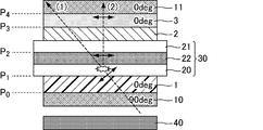
- FIG. 1 is a schematic cross-sectional view of a liquid crystal display device according to Embodiment 1.
- FIG. FIG. 3 is a schematic cross-sectional view illustrating a state of light incident from an oblique direction in the liquid crystal display device according to the first embodiment.
- the liquid crystal display device which concerns on Embodiment 1 it is a figure which shows the transition of a polarization state on the Poincare sphere when the light incident from an oblique direction is not scattered.
- the transition of the polarization state when light incident from an oblique direction is scattered in the direction perpendicular to the observation surface by the lower substrate is shown on the Poincare sphere.
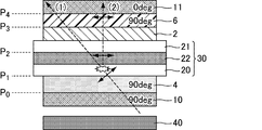
- FIG. 6 is a schematic cross-sectional view of a liquid crystal display device according to Embodiment 2.
- FIG. In the liquid crystal display device which concerns on Embodiment 2, it is a cross-sectional schematic diagram which shows the mode of the light incident from the diagonal direction.
- the liquid crystal display device which concerns on Embodiment 2 it is a figure which shows the transition of a polarization state when the light which enters from an oblique direction is not scattered on a Poincare sphere.
- it is a figure which shows the transition of a polarization state on the Poincare sphere when the light which injected from an oblique direction is scattered in a perpendicular direction with respect to an observation surface by the lower board
- FIG. 6 is a schematic cross-sectional view of a liquid crystal display device according to Embodiment 3.
- FIG. In the liquid crystal display device which concerns on Embodiment 3, it is a cross-sectional schematic diagram which shows the mode of the light which injects from the diagonal direction. In the liquid crystal display device which concerns on Embodiment 3, it is a figure which shows the transition of a polarization state when the light which enters from an oblique direction is not scattered on a Poincare sphere.
- the liquid crystal display device which concerns on Embodiment 3 it is a figure which shows the transition of a polarization state on the Poincare sphere when the light which injected from an oblique direction is scattered in a perpendicular
- the liquid crystal display device which concerns on the comparative form 1 it is a cross-sectional schematic diagram which shows the mode of the light which injected from the diagonal direction.
- liquid crystal display device which concerns on the comparative form 1 it is a figure which shows the transition of a polarization state on the Poincare sphere when the light which injected from an oblique direction is scattered in a perpendicular direction with respect to an observation surface by a lower board
- the liquid crystal display device which concerns on the comparison form 2 it is a cross-sectional schematic diagram which shows the mode of the light which injects from the diagonal direction.
- liquid crystal display device which concerns on the comparative form 2 it is a figure which shows the transition of a polarization state on the Poincare sphere when the light which injected from an oblique direction is scattered in a perpendicular
- liquid crystal display device which concerns on the comparative form 3 it is a cross-sectional schematic diagram which shows the mode of the light which injected from the diagonal direction.
- a polarizer has a function of extracting polarized light (linearly polarized light) that vibrates only in a specific direction from non-polarized light (natural light), partially polarized light, or polarized light.
- polarizer in this specification refers to only a device having a polarizing function without including a protective film.
- ns is the larger of nx and ny, and the nf is the smaller of nx and ny.
- nx and ny indicate the main refractive index in the in-plane direction of the birefringent layer (also applicable to a liquid crystal panel), and nz is the main refractive index in the out-of-plane direction, that is, in the direction perpendicular to the surface of the birefringent layer.
- D represents the thickness of the birefringent layer.
- the measurement wavelength of optical parameters such as the main refractive index, phase difference, and NZ coefficient is 550 nm unless otherwise specified.
- a birefringent layer is a layer (film) having optical anisotropy.
- the birefringent layer means that one of the in-plane retardation R and the absolute value of the thickness direction retardation Rth has a value of 10 nm or more, and preferably has a value of 20 nm or more. .
- the axis angle means the absorption axis of a polarizer or the slow axis of a birefringent layer unless otherwise specified.
- the liquid crystal display device 50 of the present embodiment is a transmissive liquid crystal display device, and as shown in FIG. 1, in order from the back side, a backlight (BL) unit 40, a first polarizer 10, and a first type of composite device.
- BL backlight
- first polarizer 10 first type of composite device.
- This embodiment is an embodiment according to the first and second liquid crystal display devices of the present invention.
- the material of the birefringent layer used in Embodiment 1 is not particularly limited.
- a stretched polymer film, a fixed liquid crystal material orientation, a thin plate made of an inorganic material, or the like can be used.
- the method for forming the birefringent layer is not particularly limited. In the case of a birefringent layer formed from a polymer film, for example, a solvent casting method, a melt extrusion method, or the like can be used. A method of simultaneously forming a plurality of birefringent layers by a coextrusion method may be used.
- the film may be unstretched or may be stretched.
- the stretching method is not particularly limited, and stretching is performed under the action of the shrinkage force of the heat-shrinkable film, in addition to the inter-roll tensile stretching method, the inter-roll compression stretching method, the tenter transverse uniaxial stretching method, the oblique stretching method, the longitudinal and transverse biaxial stretching method.
- a special stretching method or the like can be used.
- a birefringent layer formed of a liquid crystalline material for example, a method of applying a liquid crystalline material on an orientation-treated base film and fixing the orientation can be used.
- a method of not performing a special orientation treatment on the base film a method of removing the base film from the base film and transferring it to another film may be used. . Further, a method that does not fix the alignment of the liquid crystal material may be used.
- a birefringent layer formed from a non-liquid crystalline material the same formation method as that for a birefringent layer formed from a liquid crystalline material may be used.
- more specific description will be given for each type of birefringent layer.
- a birefringent layer (retardation film) of 0 ⁇ NZ ⁇ 1 is referred to as a first type birefringent layer.
- a film obtained by stretching a film containing a material having a positive or negative intrinsic birefringence as a component under the action of the shrinkage force of a heat-shrinkable film can be appropriately used.
- Japanese Patent No. 2818983 discloses a method for producing a birefringent layer that is stretched under the action of the shrinkage force of the heat-shrinkable film.
- a birefringent layer (retardation film) of NZ >> 1 or a so-called negative C plate is referred to as a second type birefringent layer.
- a film containing a material having a positive intrinsic birefringence as a component is subjected to longitudinal and transverse biaxial stretching processing, or a liquid crystal material such as cholesteric (chiral nematic) liquid crystal or discotic liquid crystal is applied.
- a material coated with a non-liquid crystalline material containing polyimide, polyamide, or the like can be used as appropriate.
- a birefringent layer (retardation film) of NZ ⁇ 1 is referred to as a third type birefringent layer.
- a film obtained by stretching a film containing a material having a positive intrinsic birefringence as a component can be appropriately used.
- the material having a positive intrinsic birefringence include polycarbonate, polysulfone, polyethersulfone, polyethylene terephthalate, polyethylene, polyvinyl alcohol, norbornene, triacetylcellulose, and diacylcellulose.
- a birefringent layer (retardation film) of NZ ⁇ 0 is referred to as a fourth type birefringent layer.
- the fourth kind of birefringent layer is a stretched film containing a material having a negative intrinsic birefringence as a component, and a film containing a material having a positive intrinsic birefringence as a component is acting on the shrinkage force of the heat shrinkable film What extended
- stretched and processed below can be used suitably.
- a film obtained by stretching a film containing a material having a negative intrinsic birefringence as a component is preferable.
- Examples of the material having a negative intrinsic birefringence include a resin composition containing an acrylic resin and a styrene resin, polystyrene, polyvinyl naphthalene, polyvinyl biphenyl, polyvinyl pyridine, polymethyl methacrylate, polymethyl acrylate, and an N-substituted maleimide copolymer. , Polycarbonate having a fluorene skeleton, and triacetyl cellulose (particularly those having a low degree of acetylation). Among these, from the viewpoint of optical properties, productivity, and heat resistance, a resin composition containing an acrylic resin and a styrene resin is preferable. A method for producing a film containing such a resin composition as a component is disclosed in, for example, JP-A-2008-146003.
- a birefringent layer (retardation film) of NZ ⁇ 0, a so-called positive C plate is referred to as a fourth type birefringent layer.
- a film containing a material having a negative intrinsic birefringence as a component and subjected to longitudinal and lateral biaxial stretching processing, a film coated with a liquid crystalline material such as a rod-like nematic liquid crystal, and the like can be used as appropriate. .
- the polarizer used in Embodiment 1 is not particularly limited with respect to materials and optical performance. Specifically, a polarizer or the like in which an anisotropic material such as an iodine complex having dichroism is adsorbed and oriented on a polyvinyl alcohol (PVA) film can be appropriately used.
- PVA polyvinyl alcohol
- a protective film such as a triacetyl cellulose (TAC) film may be laminated on both sides of the polarizer.
- TAC triacetyl cellulose
- the protective film is attached to the polarizer via any suitable adhesive layer (not shown).
- the birefringent layer may have the function of a protective film.
- the “adhesive layer” refers to a layer that joins surfaces of adjacent optical members and integrates them with practically sufficient adhesive force and adhesion time.
- the material for forming the adhesive layer include an adhesive and an anchor coat agent.
- the adhesive layer may have a multilayer structure in which an anchor coat layer is formed on the surface of an adherend and an adhesive layer is formed thereon. Further, it may be a thin layer that cannot be visually recognized.
- the liquid crystal cell only needs to perform black display by aligning liquid crystal molecules in the liquid crystal layer substantially perpendicularly to the substrate surface, and may perform black display when a voltage is applied. It is also possible to perform black display when adding.
- the polarizers 10 and 11 are arranged in crossed Nicols, the liquid crystal display device of the present embodiment is driven in a normally white mode when black display is performed when a voltage is applied, and no voltage is applied. When black display is sometimes performed, it is driven in a normally black mode.
- a display mode of a liquid crystal cell that performs black display when no voltage is applied for example, a VA mode is exemplified.
- the liquid crystal cell may be driven by a simple matrix method (passive matrix method), a plasma address method, or the like.
- a simple matrix method passive matrix method
- a plasma address method or the like.
- a liquid crystal cell for example, a liquid crystal layer is sandwiched between a pair of substrates on which electrodes are formed, and display is performed by applying a voltage between the electrodes.
- VA mode examples include an MVA (Multi-domain Vertical Alignment) mode, a CPA (Continuous Pinwheel Alignment) mode, a PVA (Patterned Vertical Alignment) mode, a BVA (Biased Vertical Alignment) mode, and an RTN (Reverse Twisted Nematic) mode.
- UV2A Ultra Violet Induced VA
- PSA Polymer Sustained Alignment
- IPS-VA In Plane Switching-Vertical Alignment
- TBA Transverese Bend Alignment
- the average pretilt angle of the liquid crystal molecules is preferably 80 ° or more (more preferably 85 ° or more).
- a display mode of a liquid crystal cell that performs black display when a voltage is applied for example, a TN (TwistedwNematic) mode can be given.
- the scattering of the upper substrate is more than the scattering of the lower substrate (non-observation surface side substrate).
- a small liquid crystal panel is more preferable.
- a liquid crystal panel having a color filter on array (COA) structure in which a CF layer is provided on a lower substrate together with a TFT is more preferable. Both the CF layer and the TFT cause large scattering of incident light. However, since these are concentrated on the lower substrate, the scattering of the upper substrate can be surely made smaller than the scattering of the lower substrate.
- COA color filter on array
- liquid crystal panel having the COA structure examples include a liquid crystal panel mounted on a Samsung liquid crystal television (trade name: UN46C7000).
- liquid crystal panels using a dye-based CF layer which is considered to have little scattering
- black and white panels that do not include a CF layer can make the scattering of the upper substrate close to zero and smaller than the scattering of the lower substrate. Can be preferably used.
- the backlight (BL) unit is not particularly limited.
- a light source including at least a light source such as can be used as appropriate.
- the BL unit itself includes an optical sheet such as a lens sheet or prism sheet, and has a collimating function. It may be.
- the first polarizer 10 and the second polarizer 11 are arranged so that their absorption axes are substantially orthogonal to each other.
- the term “substantially orthogonal” specifically means that the angle formed by the absorption axes of each other is within a range of 90 ⁇ 3 ° (preferably 90 ⁇ 1 °, more preferably 90 ⁇ 0.5 °). That means.
- the first type birefringent layer 1 is arranged so that the in-plane slow axis is substantially parallel to the absorption axis of the second polarizer 11, and the first type birefringent layer 3 is an in-plane slow phase.
- the axis is arranged so as to be substantially parallel to the absorption axis of the second polarizer 11.
- substantially parallel means that in any case, specifically, the angle formed by the in-plane slow layer axis and the absorption axis is 0 ⁇ 3 ° (preferably 0 ⁇ 1 °, more preferably 0 ⁇ 0.5 °).
- the NZ coefficient NZ11 of the first type birefringent layer 1 satisfies 0 ⁇ NZ11 ⁇ 0.5, and the in-plane retardation R11 of the first type birefringent layer 1 satisfies 220 nm ⁇ R11 ⁇ 320 nm.
- the NZ coefficient NZ12 of the first type birefringent layer 3 satisfies 0.5 ⁇ NZ12 ⁇ 1.0, and the in-plane retardation R12 of the first type birefringent layer 3 satisfies 220 nm ⁇ R12 ⁇ 320 nm. Fulfill.
- the sum of the thickness direction retardation Rth2 of the second birefringent layer 2 and the thickness direction retardation Rthlc of the liquid crystal cell 30 during black display satisfies ⁇ 50 nm ⁇ Rth2 + Rthlc ⁇ 50 nm.
- liquid crystal display device 50 of the first embodiment light obliquely incident on the substrate 20 is absorbed by the second polarizer 11 even if the traveling direction is changed to the normal direction due to scattering, and thus light leakage is suppressed. A large CR improvement effect is obtained.
- light that is obliquely incident on the substrate 20 and is transmitted through the liquid crystal cell 30 without being scattered is also absorbed by the second polarizer 11, thereby reducing light leakage from the oblique direction.
- the viewing angle can be enlarged.
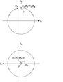
- FIG. 2 is a schematic cross-sectional view showing a state in which light is incident on the liquid crystal display device of the first embodiment (no voltage applied, black display state) from an oblique direction of 45 ° polar angle and 60 °.
- the light is shown. Since the second birefringent layer 2 and the VA liquid crystal layer have no in-plane anisotropy, the axis angle is not shown in FIG.
- Poincare sphere The concept of Poincare sphere is widely known in the field of crystal optics and the like as a useful technique for tracking the polarization state changing through the birefringent layer (for example, Hiroshi Takasaki, “Crystal optics”, Morikita Publishing, 1975, p.146-163).
- right-handed polarized light is represented in the upper hemisphere
- left-handed polarized light is represented in the lower hemisphere
- linearly polarized light is represented in the equator
- right circularly polarized light and left circularly polarized light are represented in the upper and lower poles.
- the two polarization states that are symmetric with respect to the center of the sphere form a pair of orthogonal polarization because the absolute values of the ellipticity angles are equal and the polarities are opposite.
- the effect of the birefringent layer on the Poincare sphere is that the polarization state immediately before passing through the birefringent layer is expressed by the slow axis on the Poincare sphere (more precisely, the natural vibration of two birefringent layers).
- the change in the polarization state of the light of (1) above is the polarization state each time the light emitted from the backlight unit 40 passes through the first polarizer 10, each birefringent layer, and the liquid crystal layer 22 (VA liquid crystal layer).
- Point E is a point representing the polarization state of the extinction position (polarized light oscillating in the absorption axis direction) of the second polarizer 11 when viewed from an oblique direction of 45 ° azimuth and 60 ° polar angle.
- a point P0 representing the polarization state of the light after passing through the first polarizer 10 passes through the first-type birefringent layer 1 to P1, passes through the liquid crystal layer 22 to P2, and second-type birefringence. By passing through the layer 2, it is converted to P3, and by passing through the first kind birefringent layer 3, it is converted to P4.
- the polar angle is 45 °.
- Light incident from an oblique direction of 60 ° is finally absorbed by the second polarizer 11. That is, the original function of the retardation film, which reduces the light leakage from the oblique direction and expands the viewing angle, is working normally.
- the point P0 representing the polarization state of the light after passing through the first polarizer 10 is converted to P1 by passing through the first type birefringent layer 1, and then scattered by the lower substrate 20, whereby the law Although the traveling direction is changed to the linear direction, it may be considered that the polarization state hardly changes before and after the scattering (see, for example, Non-Patent Document 2), so even after the scattering progresses in the normal direction.
- Points P2 and P3 representing the polarization state after passing through do not change from P1.
- P3 undergoes rotational movement around the slow axis on the Poincare sphere of the retardation film 3, but the slow axis of the retardation film 3 is Poincare sphere.
- the liquid crystal display device 51 of the present embodiment is a transmissive liquid crystal display device, and as shown in FIG. 5, in order from the back side, a backlight (BL) unit 40, a first polarizer 10, and a first type of composite device.
- a refraction layer 4 (corresponding to the first first birefringent layer), a liquid crystal cell 30 including a liquid crystal layer 22 sandwiched between the substrates 20 and 21, a second birefringent layer 2, a first birefringent layer.
- This is a liquid crystal display device obtained by laminating the refractive layer 6 (corresponding to the above-mentioned second type birefringent layer) and the second polarizer 11 in this order.
- the present embodiment is the same as the first embodiment. Therefore, in the following, items different from the first embodiment will be mainly described.
- This embodiment is an embodiment according to the first and third liquid crystal display devices of the present invention.
- the NZ coefficient NZ11 of the first type birefringent layer 4 satisfies 0.5 ⁇ NZ11 ⁇ 1.0, and the in-plane retardation R11 of the first type birefringent layer 4 satisfies 220 nm ⁇ R11 ⁇ 320 nm.
- the NZ coefficient NZ12 of the first type birefringent layer 6 satisfies 0 ⁇ NZ12 ⁇ 0.5, and the in-plane retardation R12 of the first type birefringent layer 6 satisfies 220 nm ⁇ R12 ⁇ 320 nm.
- the first type birefringent layer 4 is disposed so that the in-plane slow axis is substantially parallel to the absorption axis of the second polarizer 11, and the first type birefringent layer 6 is provided with an in-plane slow phase.
- the axis is arranged so as to be substantially parallel to the absorption axis of the second polarizer 11.
- substantially parallel means that in any case, specifically, the angle formed by the in-plane slow layer axis and the absorption axis is 0 ⁇ 3 ° (preferably 0 ⁇ 1 °, more preferably 0 ⁇ 0.5 °).
- liquid crystal display device 51 of the second embodiment According to the liquid crystal display device 51 of the second embodiment, light obliquely incident on the substrate 20 is absorbed by the second polarizer 11 even if the traveling direction is changed to the normal direction due to scattering, and thus light leakage is suppressed. A large CR improvement effect is obtained. In addition, light that is obliquely incident on the substrate 20 and is transmitted through the liquid crystal cell 30 without being scattered is also absorbed by the second polarizer 11, thereby reducing light leakage from the oblique direction. The viewing angle can be enlarged.
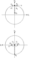
- FIG. 6 is a schematic cross-sectional view showing a state in which light is incident on the liquid crystal display device of the second embodiment (no voltage applied, black display state) from an oblique direction of 45 ° polar angle and 60 °.
- the polarization state P4 after passing through the first birefringent layer 6 of the light of (1) is the second. This coincides with the extinction position E of the polarizer 11.
- the polarization state P4 of the light (2) after passing through the first-type birefringent layer 6 matches the extinction position E ′ of the second polarizer 11. That is, since scattering on the substrate 20 is not observed as light leakage in the normal direction, a high CR can be obtained in the normal direction.
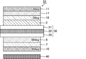
- the liquid crystal display device 52 of this embodiment is a transmissive liquid crystal display device. As shown in FIG. 9, the backlight (BL) unit 40, the first polarizer 10, and the fifth type of composite are sequentially arranged from the back side.
- Refractive layer 7 positive C plate
- This is a liquid crystal display device obtained by laminating a birefringent layer 17 (positive C plate) and a second polarizer 11 in this order.
- the fifth type birefringent layer 7 and the third type birefringent layer 8 are provided instead of the first type birefringent layer 1, the fifth type birefringent layer 7 and the third type birefringent layer 8 are provided.
- the present embodiment is the same as the first embodiment except that the birefringent layer 18 and the fifth birefringent layer 17 are provided. Therefore, in the following, items different from the first embodiment will be mainly described.
- This embodiment is an embodiment according to the first liquid crystal display device of the present invention.
- the third birefringent layer 8 is arranged so that the in-plane slow axis is substantially perpendicular to the absorption axis of the second polarizer 11, and the third birefringent layer 18 has an in-plane slow axis. It arrange
- substantially parallel means that in any case, specifically, the angle formed by the in-plane slow layer axis and the absorption axis is 0 ⁇ 3 ° (preferably 0 ⁇ 1 °, more preferably 0 ⁇ 0.5 °).
- liquid crystal display device 52 of the third embodiment light obliquely incident on the substrate 20 is absorbed by the second polarizer 11 even if the traveling direction is changed to the normal direction due to scattering, and thus light leakage is suppressed. A large CR improvement effect is obtained.
- light that is obliquely incident on the substrate 20 and is transmitted through the liquid crystal cell 30 without being scattered is also absorbed by the second polarizer 11, thereby reducing light leakage from the oblique direction.
- the viewing angle can be enlarged.
- the axial angles of the first polarizer 10 and the second polarizer 11 are set to 90 ° and 0 ° azimuth, respectively, and the in-plane slow axis of the third birefringent layer 8 is set to 90 ° azimuth.
- the in-plane slow axis of the third type birefringent layer 18 was set to 0 ° azimuth.
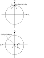
- FIG. 10 is a schematic cross-sectional view showing a state in which light is incident on the liquid crystal display device of the third embodiment (no voltage applied, black display state) from an oblique direction of 45 ° polar angle and 60 °.
- the polarization state P6 of the light (1) after passing through the fifth birefringent layer 17 is This coincides with the extinction position E of the two polarizers 11.
- the polarization state P6 of the light (2) after passing through the fifth birefringent layer 17 coincides with the extinction position E ′ of the second polarizer 11. That is, since scattering on the substrate 20 is not observed as light leakage in the normal direction, a high CR can be obtained in the normal direction.
- the order of the birefringent layers may be changed.
- each birefringent layer does not necessarily have to be uniaxial (A plate, C plate), and may be a biaxial AC plate (third birefringent layer or fourth birefringent layer). Good.
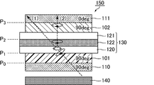
- the substrate 120 includes a thin film transistor (TFT) and a color filter layer.
- TFT thin film transistor
- the axial angles of the first polarizer 110 and the second polarizer 111 are set to 90 ° and 0 ° azimuth, respectively.
- the in-plane slow axes of the birefringent layers 101 and 102 are both set to 90 ° azimuth.
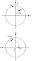
- a point P0 representing the polarization state of light after passing through the polarizer 1 passes through the birefringent layer 101, passes through the liquid crystal layer 122, passes through P2, and passes through the birefringent layer 102 through P3. Converted.
- the point P3 representing this polarization state coincides with the point E representing the polarization state of the extinction position when viewed from an oblique direction of 45 ° and polar angle 60 ° of the second polarizer 111.
- Light incident from an oblique direction with an angle of 60 ° is finally absorbed by the second polarizer 111. That is, the original function of the birefringent layer, which reduces the light leakage from the oblique direction and widens the viewing angle, is working normally.
- the point P0 representing the polarization state of the light after passing through the first polarizer 110 is converted to P1 by transmitting through the birefringent layer 101, and then scattered by the lower substrate 120, so that the traveling direction in the normal direction.
- the point representing the polarization state remains P1 even after scattering and progressing in the normal direction.
- the liquid crystal layer 122 VA liquid crystal layer
- the polarization state conversion is not performed for the incidence in the normal direction, and thus the point P2 representing the polarization state after passing through it. Does not change from P1.
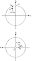
- the amount of light leakage increases as the distance between the point P3 and the point E ′ increases. More precisely, it is proportional to sin 2 ((1/2) ⁇ ⁇ P3OE ′) (the point O represents the center of the Poincare sphere. Also, since P3 and E ′ are points on the Poincare sphere, Note that the angle must not be measured in a projection map such as in Fig. 15).
- ⁇ PnOE ′ is not changed before and after the conversion.
- the birefringent layer 102 and the comparative example 1 are not limited to the birefringent layer (retardation film) of the VA mode. Since it is arranged perpendicularly or parallel to the absorption axis of the child, the polarization conversion by the retardation film after the traveling direction has changed to the normal direction due to scattering is all rotational movement about the S2 axis on the Poincare sphere. .
- the amount of light leakage from the second polarizer after scattering does not require an accurate determination of the polarization state Pn immediately before incidence on the second polarizer (P1 in the case of comparative form 1) If you know, you can estimate. It may be considered that the light leakage amount is small as P1 is close to E ′, and the light leakage amount is increased as P1 is separated from E ′. If P1 overlaps with E ′, the amount of light leakage is minimized.
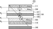
- the substrate 120 includes a thin film transistor (TFT) and a color filter layer.
- TFT thin film transistor
- the axial angles of the first polarizer 110 and the second polarizer 111 are set to 90 ° and 0 ° azimuth, respectively.
- the in-plane slow axis of the birefringent layer 103 is set to 90 ° azimuth, and the in-plane slow axis of the birefringent layer 104 is set to 0 ° azimuth.
- the point P3 indicating the polarization state of the light of the above (2) scattered by the lower substrate 120 of the liquid crystal cell 130 and changing the traveling direction to the normal direction of the second polarizer 111 is Since it does not coincide with the point E ′ representing the polarization state of the extinction position in the normal direction of the second polarizer 111, light incident from an oblique direction of 45 ° and polar angle of 60 ° is scattered by the lower substrate of the liquid crystal panel.
- the traveling direction is changed to the linear direction, the second polarizer 111 eventually leaks light. That is, the CR is lower than that of the liquid crystal display device of the embodiment. Further, even when compared with the liquid crystal display device of Comparative Example 1, the distance between P3 and E ′ is large and the CR is low.
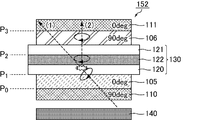
- the substrate 120 includes a thin film transistor (TFT) and a color filter layer.
- TFT thin film transistor
- the axial angles of the first polarizer 110 and the second polarizer 111 are set to 90 ° and 0 ° azimuth, respectively.
- the in-plane slow axis of the birefringent layer 105 is set to 0 ° azimuth, and the in-plane slow axis of the birefringent layer 106 is set to 90 ° azimuth.
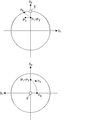
- the point P3 indicating the polarization state of the light of the above (2) scattered by the lower substrate 120 of the liquid crystal cell 130 and changing the traveling direction to the normal direction of the second polarizer 111 is Since it does not coincide with the point E ′ representing the polarization state of the extinction position in the normal direction of the second polarizer 111, light incident from an oblique direction of 45 ° and polar angle of 60 ° is scattered by the lower substrate of the liquid crystal panel.
- the traveling direction is changed to the linear direction, the second polarizer 111 eventually leaks light. That is, the CR is lower than that of the liquid crystal display device of the embodiment. Further, even when compared with the liquid crystal display device of Comparative Example 1, the distance between P3 and E ′ is large and the CR is low.
- Example 1 As the liquid crystal display device of Example 1, the liquid crystal display device 50 of Embodiment 1 was actually manufactured.
- NB norbornene
- a negative C plate having an Rth of ⁇ 270 nm was used.
- Polyimide (PI) was used as a material for this birefringent layer.
- a material for the birefringent layer norbornene (NB) was used.
- NB norbornene
- the liquid crystal cell 30 a liquid crystal cell mounted on a Samsung liquid crystal television (trade name: UN46C7000) having a COA structure was used. The Rth at the time of black display with no voltage applied to the liquid crystal cell was 272 nm.
- Example 2 (Examples 2 to 4 and Comparative Examples 1 to 3) The liquid crystal display device of Example 1 except that at least one of the in-plane retardation (R), thickness direction retardation (Rth), and NZ coefficient (NZ) of the first type birefringent layers 1 and 3 is changed.
- liquid crystal display devices of Examples 2 to 4 and Comparative Examples 1 to 3 were produced.
- NZ 0.9 birefringent layer was used.
- Example 5 As the liquid crystal display device of Example 5, the liquid crystal display device 51 of Embodiment 2 was actually manufactured.
- norbornene (NB) As a material for the birefringent layer, norbornene (NB) was used.
- norbornene (NB) was used as a material for the birefringent layer. The rest is the same as the first embodiment.
- Example 6 (Examples 6 to 8 and Comparative Examples 4 to 6) The liquid crystal display device of Example 5 except that at least one of the in-plane retardation (R), thickness direction retardation (Rth), and NZ coefficient (NZ) of the first type birefringent layers 4 and 6 is changed.
- liquid crystal display devices of Examples 6 to 8 and Comparative Examples 4 to 6 were produced.
- Comparative Example 7 As a liquid crystal display device of Comparative Example 7, a liquid crystal display device 150 of Comparative Example 1 was actually manufactured.
- TAC triacetyl cellulose
- As a material for the birefringent layer norbornene (NB) was used. The rest is the same as the first embodiment.
- CR ratio measurement method for liquid crystal display devices The measurement was performed using an ultra-low luminance spectroradiometer (manufactured by TOPCON, trade name: SR-Ul1). The luminance of white display and black display in the normal direction was measured, and the ratio was taken as CR.
- the contrast ratio was 7000 or more.
- the contrast ratio was less than 7000.
- Visual evaluation also confirmed that the liquid crystal display devices of Examples 1 to 8 had higher CR than the liquid crystal display devices of Comparative Examples 1 to 9.
Landscapes
- Physics & Mathematics (AREA)
- Nonlinear Science (AREA)
- General Physics & Mathematics (AREA)
- Optics & Photonics (AREA)
- Mathematical Physics (AREA)
- Chemical & Material Sciences (AREA)
- Crystallography & Structural Chemistry (AREA)
- Liquid Crystal (AREA)
Abstract
La présente invention porte sur un dispositif d'affichage à cristaux liquides présentant une fuite de lumière supprimée et un rapport de contraste amélioré. Un mode de réalisation de la présente invention est un dispositif d'affichage à cristaux liquides qui comporte, en séquence, un premier polariseur, une première couche biréfringente d'un premier type, une cellule de cristaux liquides et un second polariseur, dans cet ordre à partir du côté de surface arrière. La cellule de cristaux liquides comprend une paire de substrats qui se font mutuellement face et une couche de cristaux liquides qui est maintenue entre les substrats. L'axe lent dans le plan de la première couche biréfringente d'un premier type est sensiblement parallèle à l'axe d'absorption du second polariseur, et l'axe d'absorption du premier polariseur est sensiblement perpendiculaire à l'axe d'absorption du second polariseur. Quand le coefficient NZ de la première couche biréfringente d'un premier type est représenté par NZ11 et que le retard dans le plan est représenté par R11, (1) 0 < NZ11 ≤ 0,5 et (2) 220 nm ≤ R11 ≤ 320 nm sont satisfaites.
Applications Claiming Priority (2)
| Application Number | Priority Date | Filing Date | Title |
|---|---|---|---|
| JP2011021157 | 2011-02-02 | ||
| JP2011-021157 | 2011-02-02 |
Publications (1)
| Publication Number | Publication Date |
|---|---|
| WO2012105428A1 true WO2012105428A1 (fr) | 2012-08-09 |
Family
ID=46602644
Family Applications (1)
| Application Number | Title | Priority Date | Filing Date |
|---|---|---|---|
| PCT/JP2012/051753 Ceased WO2012105428A1 (fr) | 2011-02-02 | 2012-01-27 | Dispositif d'affichage à cristaux liquides |
Country Status (1)
| Country | Link |
|---|---|
| WO (1) | WO2012105428A1 (fr) |
Cited By (1)
| Publication number | Priority date | Publication date | Assignee | Title |
|---|---|---|---|---|
| US11927850B2 (en) * | 2022-05-16 | 2024-03-12 | Sharp Display Technology Corporation | Liquid crystal display device |
Citations (3)
| Publication number | Priority date | Publication date | Assignee | Title |
|---|---|---|---|---|
| JP2001350022A (ja) * | 2000-04-07 | 2001-12-21 | Tatsuo Uchida | 広視野角偏光板 |
| JP2003321634A (ja) * | 2002-05-01 | 2003-11-14 | Canon Inc | インク、カラーフィルターとその製造方法、液晶パネル、コンピュータ及び画像表示デバイス |
| JP2010039432A (ja) * | 2008-08-08 | 2010-02-18 | Sumitomo Chemical Co Ltd | 位相差フィルムの製造方法 |
-
2012
- 2012-01-27 WO PCT/JP2012/051753 patent/WO2012105428A1/fr not_active Ceased
Patent Citations (3)
| Publication number | Priority date | Publication date | Assignee | Title |
|---|---|---|---|---|
| JP2001350022A (ja) * | 2000-04-07 | 2001-12-21 | Tatsuo Uchida | 広視野角偏光板 |
| JP2003321634A (ja) * | 2002-05-01 | 2003-11-14 | Canon Inc | インク、カラーフィルターとその製造方法、液晶パネル、コンピュータ及び画像表示デバイス |
| JP2010039432A (ja) * | 2008-08-08 | 2010-02-18 | Sumitomo Chemical Co Ltd | 位相差フィルムの製造方法 |
Cited By (1)
| Publication number | Priority date | Publication date | Assignee | Title |
|---|---|---|---|---|
| US11927850B2 (en) * | 2022-05-16 | 2024-03-12 | Sharp Display Technology Corporation | Liquid crystal display device |
Similar Documents
| Publication | Publication Date | Title |
|---|---|---|
| JP4669909B2 (ja) | 液晶表示装置 | |
| US9348176B2 (en) | Liquid crystal display device | |
| JP4792545B2 (ja) | 液晶表示装置 | |
| JP4538096B2 (ja) | 液晶表示装置 | |
| JP5330529B2 (ja) | 液晶表示装置 | |
| US8179508B2 (en) | Liquid crystal display device having first and second polarizers and first and second birefringent layers | |
| JP5259824B2 (ja) | 液晶表示装置 | |
| CN101395503B (zh) | 用于改善tn-lcd的视角的整合型o膜及包括该膜的偏光板和tn-lcd | |
| CN102782571B (zh) | 具有良好的视角和彩色特性的ecb-lcd | |
| WO2012090769A1 (fr) | Elément optique et dispositif d'affichage à cristaux liquides | |
| WO2012133137A1 (fr) | Dispositif d'affichage à cristaux liquides | |
| WO2013111867A1 (fr) | Dispositif d'affichage à cristaux liquides | |
| WO2012133155A1 (fr) | Dispositif d'affichage à cristaux liquides | |
| WO2012105428A1 (fr) | Dispositif d'affichage à cristaux liquides | |
| WO2012133141A1 (fr) | Dispositif d'affichage à cristaux liquides | |
| WO2012133140A1 (fr) | Dispositif d'affichage à cristaux liquides |
Legal Events
| Date | Code | Title | Description |
|---|---|---|---|
| 121 | Ep: the epo has been informed by wipo that ep was designated in this application |
Ref document number: 12741817 Country of ref document: EP Kind code of ref document: A1 |
|
| NENP | Non-entry into the national phase |
Ref country code: DE |
|
| 122 | Ep: pct application non-entry in european phase |
Ref document number: 12741817 Country of ref document: EP Kind code of ref document: A1 |
|
| NENP | Non-entry into the national phase |
Ref country code: JP |