WO2012105604A1 - Radeau de sauvetage - Google Patents
Radeau de sauvetage Download PDFInfo
- Publication number
- WO2012105604A1 WO2012105604A1 PCT/JP2012/052259 JP2012052259W WO2012105604A1 WO 2012105604 A1 WO2012105604 A1 WO 2012105604A1 JP 2012052259 W JP2012052259 W JP 2012052259W WO 2012105604 A1 WO2012105604 A1 WO 2012105604A1
- Authority
- WO
- WIPO (PCT)
- Prior art keywords
- diameter
- fluid
- hollow hole
- hoses
- compressed fluid
- Prior art date
- Legal status (The legal status is an assumption and is not a legal conclusion. Google has not performed a legal analysis and makes no representation as to the accuracy of the status listed.)
- Ceased
Links
Images



Classifications
-
- B—PERFORMING OPERATIONS; TRANSPORTING
- B63—SHIPS OR OTHER WATERBORNE VESSELS; RELATED EQUIPMENT
- B63C—LAUNCHING, HAULING-OUT, OR DRY-DOCKING OF VESSELS; LIFE-SAVING IN WATER; EQUIPMENT FOR DWELLING OR WORKING UNDER WATER; MEANS FOR SALVAGING OR SEARCHING FOR UNDERWATER OBJECTS
- B63C9/00—Life-saving in water
- B63C9/02—Lifeboats, life-rafts or the like, specially adapted for life-saving
- B63C9/04—Life-rafts
-
- B—PERFORMING OPERATIONS; TRANSPORTING
- B63—SHIPS OR OTHER WATERBORNE VESSELS; RELATED EQUIPMENT
- B63C—LAUNCHING, HAULING-OUT, OR DRY-DOCKING OF VESSELS; LIFE-SAVING IN WATER; EQUIPMENT FOR DWELLING OR WORKING UNDER WATER; MEANS FOR SALVAGING OR SEARCHING FOR UNDERWATER OBJECTS
- B63C9/00—Life-saving in water
- B63C9/06—Floatable closed containers with accommodation for one or more persons inside
Definitions
- the present invention relates to a life preserver, and more particularly, a saddle body is configured by using a fluid introduction type hollow hole forming tube in which a large-diameter hollow hole is formed in a central part by introduction of a fluid, such as a marine accident.
- the present invention relates to a capsule life-saving device in which the fluid introduction type hollow hole forming tube is expanded to form a large-diameter hollow hole and the large-diameter hollow hole is used as a rescue room.
- Aircraft and ships of a predetermined size are required by law and regulations to be equipped with life-saving equipment such as escape boats and lifeboats.
- lifeboats and lifeboats have various specifications and structures, but they are generally lightweight, easy to handle, and have features such as easy assembly of awnings and the like.
- a typical life preserver is disclosed in Patent Document 1 below, for example.
- FIG. 6 shows a life preserver described in the following Patent Document 1
- FIG. 6A is an overall perspective view
- FIG. 6B is a perspective view in a state where the canopy is removed from FIG. 6A.
- the lifesaving rod 30 includes a rod body 31 made of a cylindrical tube and a canopy 36 made of a canopy covering the bag body.
- the eaves body 31 includes a base structure 33 having a floor 32, and an upper structure 34 that constitutes a column and a roof column erected from the base structure, and both the base structure 33 and the upper structure 34 are formed of a cylindrical tube. These cylindrical tubes are connected to each other to form two closed air circuits. These air circuits are inflated by first and second gas cylinders (not shown).
- first and second gas cylinders are supported immediately below the base structure, and the first gas cylinder expands the base structure 33 and the second cylinder expands the upper structure 34.
- the length of the cylindrical tube of the rod main body 31 is changed depending on the position of the tube portion in the structure.
- These cylindrical tubes are also provided with a gas cylinder valve and a gas vent valve 35.
- the gas vent valve 35 serves to ensure that the excess air is evacuated and the air circuit is expanded to the desired pressure.
- the lifeboat of the above-mentioned patent document 1 it is normally in a folded state, and in the case of a marine accident, a cylindrical tube constituting the bag body expands to form a rescue room of a predetermined size inside.
- the life-saving person can enter this rescue room.
- this life preserver has the following problems in view of its configuration. First, the cylindrical tube that constitutes the main body of the bag is divided into a plurality of cylindrical tube portions, and these tube portions are connected to each other and bent in a complicated manner. For this reason, there are many cylindrical tube parts, the shape is complicated, and the manufacture becomes troublesome, and also the size and the shape are different, and it is not possible to manufacture an arbitrary size in particular.
- this life raft since these bent parts are bent at a substantially right angle, even if air is injected in an emergency, the air resistance increases, and it takes time to expand. . Furthermore, since this life raft has about two air chambers, when an obstacle or the like touches or collides with the cylindrical tube, it bursts due to perforation or breakage, and the gas leaks from these breakage points and can be used. There is a risk of disappearing. In particular, this type of life raft is used in a marine accident area where there are many drifting objects or a marine accident area where there is a lot of debris flow and exposed rocks, so there is a greater chance of contact damage.
- the present invention has been made to solve such a problem that the conventional technology potentially has, and the object of the present invention can be easily and inexpensively manufactured in an arbitrary size and / or shape. To provide a life preserver.
- Another object of the present invention is to provide a life raft that can be safely used as it is even if an obstacle collides with it and even a part of the object is punctured.
- the lifeboat of the first aspect of the present invention is a lifeboat provided with a main body that bulges by introduction of a compressed fluid and forms a floating body.
- the saddle body has a plurality of annular small-diameter hoses having a large-diameter hollow hole in the center and swelled by introduction of a compressed fluid so that the hollow holes coincide with each other in the longitudinal direction.
- a fluid introduction type hollow hole forming tube is formed in which a large-diameter opening having the large-diameter diameter is formed at both ends and a large-diameter hollow hole communicating with the large-diameter opening is formed inside.
- the fluid introduction type hollow hole forming tube is formed in a donut shape by connecting the large-diameter openings at both ends in communication with each other, and an inlet / outlet is provided on a side wall surface of the portion raised from the water,
- a boarding assisting member is attached to the inner space of the doughnut-shaped fluid introduction type hollow hole forming tube.
- a device for introducing a compressed fluid into the fluid introduction type hollow hole forming tube is disposed in the loading assisting member. It is characterized by that.
- the lifeboat of the third aspect is the lifeboat of the first or second aspect, wherein the cage main body is a fluid introduction device in which fluid is simultaneously introduced into each fluid introduction portion of the plurality of annular small-diameter hoses. A ring is connected.
- the lifeboat of the fourth aspect is the lifeboat of any of the first to third aspects, wherein the fluid introduction type hollow hole forming tube is flexible so that the adjacent annular small diameter hose can be directly or foldable. It is characterized by being bonded by a sheet material made of a material having a property.
- the bag main body is formed of a plurality of annular small-diameter hoses, the size and / or shape of these small-diameter hoses can be easily changed to any size or / and shape.
- a life preserver can be manufactured at a low cost. Even if an obstacle collides with the main body of the bag, even if a part is ruptured by drilling or the like, it can be safely used as it is. In addition, it is possible to safely enter and exit the rescue room using a boarding assisting member.
- the life preserver equipped with the life preserver becomes compact.
- the introduction of the compressed fluid into the plurality of annular small-diameter hoses is simultaneously performed, and the formation of the fluid introduction type hollow hole forming tube becomes rapid.
- the adjacent annular small-diameter hose is joined directly or with a sheet material made of a flexible and flexible material, so that the fluid introduction type hollow hole forming tube can be easily obtained. Can be made.
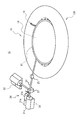
- FIG. 1 is a schematic perspective view of a life-saving device equipped with a life-saving device according to Embodiment 1.
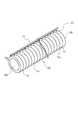
- FIG. It is a perspective view in the state where a compressed fluid was introduced into an annular small diameter hose and a tube was extended.
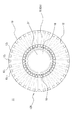
- 4A is a schematic cross-sectional view taken along the line IVA-IVA in FIG. 1
- FIGS. 4B and 4C are schematic cross-sectional views in a state where a compressed fluid is removed.
- FIG. 5 is a cross-sectional view taken along line VV in FIG. 1.
- 6A and 6B show a conventional lifesaving device
- FIG. 6A is an overall perspective view
- FIG. 6B is a perspective view with a canopy removed.
- FIG. 1 is a schematic perspective view of a life preserver according to Embodiment 1 of the present invention
- FIG. 2 is a schematic perspective view of a life preserver apparatus equipped with a life preserver according to Embodiment 1
- FIG. 3 is a compressed fluid in an annular small diameter hose.
- 4A is a schematic cross-sectional view taken along the line IVA-IVA in FIG. 1
- FIGS. 4B and 4C are schematic cross-sectional views in a state where the compressed fluid is removed.
- 5 is a cross-sectional view taken along line VV in FIG.
- a life support device 10 having a life preserver according to Embodiment 1 of the present invention includes a life preserver 11 and a compressed fluid introduction / extraction device 20 that extracts a fluid such as air introduced or introduced into the life preserver. It is configured.
- the life preserver 11 and the compressed fluid introduction / extraction device 20 are connected by a connecting pipe 24 via a switching valve 23, and a flow meter and a pressure gauge (not shown) are provided in the middle of the connecting pipe 24.
- the lifesaving device 10 is mounted on a ship or the like, and the lifesaving device 11 is normally folded and stored in a storage case (not shown) or the like.
- a plurality of annular small-diameter hoses (hereinafter referred to as “annular hoses”) 12 1 to 12 n , which will be described later, are expanded by introducing compressed fluid.
- the hollow hole 12c is formed, and it becomes a donut-shaped ridge which can use this large diameter hollow hole 12c as the rescue room R.
- individual members constituting the lifesaving device 10 will be described in detail.
- the life preserver 11 includes a saddle body 12A in which a rescue chamber R is formed by introduction of a compressed fluid, and the saddle body 12A has a large central portion.
- a plurality of annular hoses 12 1 to 12 n each having a hollow hole 12 having a diameter D2 constitute a fluid introduction type hollow hole forming tube (hereinafter referred to as a tube) 12, and this tube 12 is a bag main body 12A. It has become.
- FIG. 3 shows a state in which an annular hose before the donut shape is provided to explain the tube.
- the plurality of annular hoses 12 1 to 12 n constituting the tube 12 have the same configuration. These annular hoses are obtained by connecting a small-diameter hose having a hollow hole 12 having a large diameter D2 at the center to an endless annular shape. A compressed fluid introduction port is provided in a part of the outer periphery, and swells by introduction of the compressed fluid. It is formed of a member. In addition, the plurality of annular hoses form a tube by connecting adjacent annular hoses directly or by a foldable sheet material made of a flexible material.
- Tube 12 when the fluid in the annular hose 12 1 ⁇ 12 n of the plurality of are not introduced, as shown in FIG. 3, tube 12, the fluid is introduced into the annular hose 12 1 ⁇ 12 n of the plurality of Then, it becomes a circular cylindrical body, but before the fluid is introduced, it is a flat and long body that is crushed.
- These annular hoses are flexible and elastic so that they can be flattened, folded and wound mechanically, and the materials are wear resistance, light weight, fire resistance, pressure resistance, high pressure, It is strong and difficult to break, has a light material property or a plurality of characteristics, and is inexpensive.
- These annular hoses are, for example, fire hoses, special polyesters, nylon hoses, and the like, which are made of a woven cloth, rubber hose, or synthetic resin hose whose inner surface is gas-sealed.
- the saddle body 12A is provided with a plurality of annular hoses 12 1 to 12 n having a hollow hole with a large diameter D2 at the center and swelled by introduction of a compressed fluid so that the respective hollow holes are aligned in the longitudinal direction.
- the compressed fluid is introduced into the annular hoses 12 1 to 12 n , the large-diameter openings 12a and 12b having the large-diameter diameter D2 at both ends and the large-diameter communicating with the large-diameter openings inside.
- the tube is formed with a hollow hole 12c (see FIG. 3), and large-diameter openings 12a and 12b at both ends of the tube are communicated to form a donut shape (see FIGS.
- An entrance 14 is provided at a place where the wall rises from the water, and a boarding assisting member 18 is attached to the space of the bowl body curved in a donut shape.
- a rescue room R is formed in the large-diameter hollow hole 12c. Configuration and You have me. By doing in this way, the bag main body can be easily produced by curving the fluid introduction type hollow hole forming tube into a donut shape. Moreover, since the entrance / exit is provided in the side wall surface, it gets in a boarding auxiliary member, and enters into the rescue room R using this auxiliary member.
- the plurality of annular hoses 12 1 to 12 n are connected to a compressed fluid introduction ring 15 for introducing a compressed fluid into the fluid introduction portion 121 of each hose.
- the compressed fluid introduction ring 15 is connected to the compressed fluid introduction / extraction device 20 by a detachable pipe joint 25.
- the compressed fluid introduction / extraction device 20 includes a compressed fluid introduction device 21 that introduces a fluid such as air into the life raft 11 and a compressed fluid extraction device 22 that extracts the introduced fluid.
- the life preserver 11 and the compressed fluid introduction / extraction device 20 are connected by a connecting pipe 24 via a switching valve 23, and a flow meter and a pressure gauge (not shown) are provided in the middle of the connecting pipe 24.
- the compressed fluid introducing device 21 includes a motor 21a, a compressor (compressor) 21b, and a storage tank 21c that stores compressed air.
- the fluid is air.
- this fluid is not limited to air, Other gas may be sufficient.
- the gas is nitrogen, hydrogen, helium gas or the like.
- a gas (explosion) used in an air bag or the like may be used instead of the compressed fluid introducing device 21, for example.
- the fluid is introduced into the tube 12, the fluid is introduced while looking at the flow meter. By detecting the flow meter, it is possible to detect a gas leak hose.
- the flowmeter was provided in the middle of the connecting pipe, you may provide it in each annular hose. Moreover, you may provide a pressure gauge in an annular hose.
- the compressed fluid extracting device 22 is a device for extracting the fluid introduced into the tube 12 and operates in the reverse manner to the compressed fluid introducing device.
- a vacuum pump or the like is used for the compressed fluid extracting device 22.
- the straight tube 12 can be folded.
- the pipe joint 25 includes a male joint connected to the connecting pipe 24 and a female joint into which the joint is inserted.
- This pipe joint 25 can be attached and detached with one touch.
- description is abbreviate
- the lifesaving device 10 operates the switching valve 23 to introduce compressed air from the compressed fluid introduction device 21 to the plurality of annular hoses 12 1 to 12 n constituting the tube 12 through the compressed fluid introduction ring 15. .
- the compressed air is introduced to form a large-diameter hollow hole 12 c communicating with the inside of the tube 12, and this large-diameter hollow hole becomes the rescue room R.
- the life raft 11 since it is composed of a tube composed of a plurality of annular hoses, there is no portion that bends at a substantially right angle or the like, it can be easily manufactured, and the sizes are different, especially those having an arbitrary size. It becomes possible to do. Moreover, even if an obstacle collides and even a part is ruptured by drilling or the like, it can be safely used as it is.
- the introduction of air from the compressed fluid introducing device 21 to the tube 12 and the extraction of air from the tube 12 by the compressed fluid extracting device 22 are repeatedly used.
- one or several of the plurality of annular hoses 12 1 to 12 n may be damaged for some reason and air may leak.
- this air leak occurs in the tube 12, if it is one or several, it functions as a tube as it is and can be used continuously. Further, when it occurs during the introduction of compressed air, it is possible to determine whether or not the tube can be used by stopping press-fitting into the broken annular hose by observing the flow meter.
- Adjacent annular small-diameter hoses may be joined to adjacent annular hoses directly or with a predetermined gap and a foldable and flexible sheet material (see FIG. 5).
Landscapes
- Engineering & Computer Science (AREA)
- Mechanical Engineering (AREA)
- Ocean & Marine Engineering (AREA)
- Emergency Lowering Means (AREA)
Abstract
L'invention concerne un radeau de sauvetage très sûr qui peut être fabriqué facilement dans une taille quelconque souhaitée à un coût faible. Le radeau (11) de sauvetage comporte un corps principal (12A) de radeau qui peut être dilaté en y introduisant un fluide comprimé. Le corps principal (12A) de radeau comporte des tubes (12) capables de former des parties creuses tandis qu'ils sont dilatés par l'introduction d'un fluide, les tubes (12) comportant une pluralité de tuyaux souples annulaires (121 à 12n) de petit diamètre susceptibles d'être dilatés par introduction d'un fluide et disposés longitudinalement de telle façon que les parties creuses (12c) soient alignées entre elles. Si un fluide comprimé est introduit dans les tuyaux souples annulaires (121 à 12n) de petit diamètre, les parties creuses (12c) présentant un grand diamètre sont formées de telle manière que les parties creuses (12c) de grand diamètre communiquent avec des ouvertures de grand diamètre des deux côtés et sur les côtés intérieurs. Les tubes (12) capables de former des parties creuses tandis qu'ils sont dilatés par l'introduction d'un fluide sont reliés en forme de tore pour raccorder les ouvertures de grand diamètre des deux côtés. Une entrée / sortie est formée dans une face de paroi latérale à une position située plus haut que la surface de l'eau. Un compartiment (R) de sauvetage est formé à l'intérieur des parties creuses de grand diamètre. Un élément (18) d'aide à l'embarquement est installé dans l'espace intérieur des tubes (12) en forme de tore capables de former des parties creuses tandis qu'ils sont dilatés par l'introduction d'un fluide.
Applications Claiming Priority (2)
| Application Number | Priority Date | Filing Date | Title |
|---|---|---|---|
| JP2011021976A JP2012162107A (ja) | 2011-02-03 | 2011-02-03 | 救命筏 |
| JP2011-021976 | 2011-02-03 |
Publications (1)
| Publication Number | Publication Date |
|---|---|
| WO2012105604A1 true WO2012105604A1 (fr) | 2012-08-09 |
Family
ID=46602811
Family Applications (1)
| Application Number | Title | Priority Date | Filing Date |
|---|---|---|---|
| PCT/JP2012/052259 Ceased WO2012105604A1 (fr) | 2011-02-03 | 2012-02-01 | Radeau de sauvetage |
Country Status (2)
| Country | Link |
|---|---|
| JP (1) | JP2012162107A (fr) |
| WO (1) | WO2012105604A1 (fr) |
Cited By (1)
| Publication number | Priority date | Publication date | Assignee | Title |
|---|---|---|---|---|
| EP3822170A1 (fr) * | 2019-11-15 | 2021-05-19 | Goodrich Corporation | Systèmes de gonflage pour glisses d'évacuation et rafts de sauvetage |
Families Citing this family (2)
| Publication number | Priority date | Publication date | Assignee | Title |
|---|---|---|---|---|
| JP5215490B1 (ja) * | 2012-05-29 | 2013-06-19 | 清 菊川 | ゴムボート |
| JP7833108B1 (ja) * | 2025-07-07 | 2026-03-19 | 清 菊川 | 柔軟かつ設置可能な携帯型放射線被ばく防止用の遮蔽空間・通路 |
Citations (2)
| Publication number | Priority date | Publication date | Assignee | Title |
|---|---|---|---|---|
| JPH0443190A (ja) * | 1990-06-08 | 1992-02-13 | Mitsubishi Heavy Ind Ltd | 大型潜水船 |
| JPH11508517A (ja) * | 1995-09-14 | 1999-07-27 | ワードル ストリーズ (セーフティー アンド サバイバル イクイップメント) リミテッド | 救命筏 |
Family Cites Families (2)
| Publication number | Priority date | Publication date | Assignee | Title |
|---|---|---|---|---|
| JPS4723899U (fr) * | 1971-03-31 | 1972-11-17 | ||
| US7056178B1 (en) * | 2005-03-08 | 2006-06-06 | Yu-Lin Chung | Amphibious tent |
-
2011
- 2011-02-03 JP JP2011021976A patent/JP2012162107A/ja active Pending
-
2012
- 2012-02-01 WO PCT/JP2012/052259 patent/WO2012105604A1/fr not_active Ceased
Patent Citations (2)
| Publication number | Priority date | Publication date | Assignee | Title |
|---|---|---|---|---|
| JPH0443190A (ja) * | 1990-06-08 | 1992-02-13 | Mitsubishi Heavy Ind Ltd | 大型潜水船 |
| JPH11508517A (ja) * | 1995-09-14 | 1999-07-27 | ワードル ストリーズ (セーフティー アンド サバイバル イクイップメント) リミテッド | 救命筏 |
Cited By (2)
| Publication number | Priority date | Publication date | Assignee | Title |
|---|---|---|---|---|
| EP3822170A1 (fr) * | 2019-11-15 | 2021-05-19 | Goodrich Corporation | Systèmes de gonflage pour glisses d'évacuation et rafts de sauvetage |
| US11554999B2 (en) | 2019-11-15 | 2023-01-17 | Goodrich Corporation | Inflation systems for evacuation slides and life rafts |
Also Published As
| Publication number | Publication date |
|---|---|
| JP2012162107A (ja) | 2012-08-30 |
Similar Documents
| Publication | Publication Date | Title |
|---|---|---|
| US9199706B2 (en) | Water rescue device | |
| CN109050819B (zh) | 一种水中航行器的自救系统 | |
| US7322309B2 (en) | Inflatable structure | |
| EP3560813B1 (fr) | Système de ballast de compartiment | |
| JP4801214B1 (ja) | 流体導入式中空孔形成チューブ及びこのチューブを用いたチューブシステム | |
| CN104527948A (zh) | 带帐篷的救生橡皮筏 | |
| JP5010057B1 (ja) | 救命筏 | |
| CN205440814U (zh) | 一种可变形双层救生圈 | |
| JP2012162107A (ja) | 救命筏 | |
| CN211766174U (zh) | 一种船用快换式防倾覆快充气囊 | |
| JP6396025B2 (ja) | ゴムボート | |
| KR101489311B1 (ko) | 인명구조용 팽창튜브 | |
| IT201700010263A1 (it) | Dispositivo salvagente estensibile | |
| CN215399265U (zh) | 用于潜水呼吸器的可提供多种充气方式的双气囊浮力背心 | |
| EP2045182A2 (fr) | Corps de déplacement fluide pour la flottation d'urgence d'une embarcation | |
| CN109292038A (zh) | 一种便携式可折叠防洪应急救生装置 | |
| KR20180014892A (ko) | 안전 수영복 | |
| JP5215490B1 (ja) | ゴムボート | |
| KR200422945Y1 (ko) | 구명보트 | |
| KR20130007879A (ko) | 구명 뗏목 | |
| CN212980502U (zh) | 一种双向快速充气的救生衣 | |
| KR20110002172U (ko) | 구명 조끼에 장착하는 조난표시용 기구 | |
| RU2725574C1 (ru) | Надувное спасательное средство "Звезда" | |
| KR101954822B1 (ko) | 구명벌 | |
| KR102134099B1 (ko) | 구난 무선 송신수단의 수상 부양체 |
Legal Events
| Date | Code | Title | Description |
|---|---|---|---|
| 121 | Ep: the epo has been informed by wipo that ep was designated in this application |
Ref document number: 12742240 Country of ref document: EP Kind code of ref document: A1 |
|
| NENP | Non-entry into the national phase |
Ref country code: DE |
|
| 122 | Ep: pct application non-entry in european phase |
Ref document number: 12742240 Country of ref document: EP Kind code of ref document: A1 |