WO2012105675A1 - 無線電力供給システム - Google Patents
無線電力供給システム Download PDFInfo
- Publication number
- WO2012105675A1 WO2012105675A1 PCT/JP2012/052449 JP2012052449W WO2012105675A1 WO 2012105675 A1 WO2012105675 A1 WO 2012105675A1 JP 2012052449 W JP2012052449 W JP 2012052449W WO 2012105675 A1 WO2012105675 A1 WO 2012105675A1
- Authority
- WO
- WIPO (PCT)
- Prior art keywords
- power
- power supply
- coil
- resonator
- resonance
- Prior art date
- Legal status (The legal status is an assumption and is not a legal conclusion. Google has not performed a legal analysis and makes no representation as to the accuracy of the status listed.)
- Ceased
Links
Images


Classifications
-
- H—ELECTRICITY
- H02—GENERATION; CONVERSION OR DISTRIBUTION OF ELECTRIC POWER
- H02J—ELECTRIC POWER NETWORKS; CIRCUIT ARRANGEMENTS OR SYSTEMS FOR SUPPLYING OR DISTRIBUTING ELECTRIC POWER; SYSTEMS FOR STORING ELECTRIC ENERGY
- H02J50/00—Circuit arrangements or systems for wireless supply or distribution of electric power
- H02J50/10—Circuit arrangements or systems for wireless supply or distribution of electric power using inductive coupling
- H02J50/12—Circuit arrangements or systems for wireless supply or distribution of electric power using inductive coupling of the resonant type
-
- H—ELECTRICITY
- H02—GENERATION; CONVERSION OR DISTRIBUTION OF ELECTRIC POWER
- H02J—ELECTRIC POWER NETWORKS; CIRCUIT ARRANGEMENTS OR SYSTEMS FOR SUPPLYING OR DISTRIBUTING ELECTRIC POWER; SYSTEMS FOR STORING ELECTRIC ENERGY
- H02J50/00—Circuit arrangements or systems for wireless supply or distribution of electric power
- H02J50/001—Energy harvesting or scavenging
-
- H—ELECTRICITY
- H02—GENERATION; CONVERSION OR DISTRIBUTION OF ELECTRIC POWER
- H02J—ELECTRIC POWER NETWORKS; CIRCUIT ARRANGEMENTS OR SYSTEMS FOR SUPPLYING OR DISTRIBUTING ELECTRIC POWER; SYSTEMS FOR STORING ELECTRIC ENERGY
- H02J50/00—Circuit arrangements or systems for wireless supply or distribution of electric power
- H02J50/005—Mechanical details of housing or structure aiming to accommodate the power transfer means, e.g. mechanical integration of coils, antennas or transducers into emitting or receiving devices
-
- H—ELECTRICITY
- H02—GENERATION; CONVERSION OR DISTRIBUTION OF ELECTRIC POWER
- H02J—ELECTRIC POWER NETWORKS; CIRCUIT ARRANGEMENTS OR SYSTEMS FOR SUPPLYING OR DISTRIBUTING ELECTRIC POWER; SYSTEMS FOR STORING ELECTRIC ENERGY
- H02J50/00—Circuit arrangements or systems for wireless supply or distribution of electric power
- H02J50/90—Circuit arrangements or systems for wireless supply or distribution of electric power involving detection or optimisation of position, e.g. alignment
-
- H—ELECTRICITY
- H04—ELECTRIC COMMUNICATION TECHNIQUE
- H04B—TRANSMISSION
- H04B5/00—Near-field transmission systems, e.g. inductive or capacitive transmission systems
- H04B5/20—Near-field transmission systems, e.g. inductive or capacitive transmission systems characterised by the transmission technique; characterised by the transmission medium
- H04B5/24—Inductive coupling
-
- H—ELECTRICITY
- H02—GENERATION; CONVERSION OR DISTRIBUTION OF ELECTRIC POWER
- H02J—ELECTRIC POWER NETWORKS; CIRCUIT ARRANGEMENTS OR SYSTEMS FOR SUPPLYING OR DISTRIBUTING ELECTRIC POWER; SYSTEMS FOR STORING ELECTRIC ENERGY
- H02J7/00—Circuit arrangements for charging or discharging batteries or for supplying loads from batteries
-
- H—ELECTRICITY
- H02—GENERATION; CONVERSION OR DISTRIBUTION OF ELECTRIC POWER
- H02J—ELECTRIC POWER NETWORKS; CIRCUIT ARRANGEMENTS OR SYSTEMS FOR SUPPLYING OR DISTRIBUTING ELECTRIC POWER; SYSTEMS FOR STORING ELECTRIC ENERGY
- H02J7/00—Circuit arrangements for charging or discharging batteries or for supplying loads from batteries
- H02J7/40—Circuit arrangements for charging or discharging batteries or for supplying loads from batteries characterised by the exchange of charge or discharge related data
- H02J7/42—Circuit arrangements for charging or discharging batteries or for supplying loads from batteries characterised by the exchange of charge or discharge related data with electronic devices having internal batteries, e.g. mobile phones
-
- H—ELECTRICITY
- H04—ELECTRIC COMMUNICATION TECHNIQUE
- H04B—TRANSMISSION
- H04B5/00—Near-field transmission systems, e.g. inductive or capacitive transmission systems
- H04B5/70—Near-field transmission systems, e.g. inductive or capacitive transmission systems specially adapted for specific purposes
- H04B5/79—Near-field transmission systems, e.g. inductive or capacitive transmission systems specially adapted for specific purposes for data transfer in combination with power transfer
Definitions
- the present invention relates to a wireless power supply system that transmits power in a contactless manner by creating a magnetic resonance state.
- the power supply technology using this magnetic field resonance state (also called magnetic resonance, magnetic field resonance, or magnetic field resonance) enables transmission of energy (electric power) by coupling a magnetic field between two resonating resonators.
- the wireless power supply technology using such a magnetic field resonance state the transmission distance of energy (electric power) can be increased as compared with the wireless power supply technology using electromagnetic induction.
- Patent Document 1 discloses that even when the distance between the power transmission resonance coil and the power reception resonance coil varies, the power transmission resonance coil and the power reception power are changed by changing the resonance frequency of the power transmission resonance coil and the resonance frequency of the power reception resonance coil.
- a wireless power supply system that can prevent a decrease in power transmission efficiency of power from a power transmission device to a power reception device by sequentially changing a coupling strength with a resonance coil to maintain a resonance state.
- Patent Document 2 discloses a wireless power device capable of increasing the power transmission efficiency of the entire device by changing the coupling strength between the power transmission coil and the power reception coil.
- Patent Document 3 a power supply system that supplies power in a contactless manner by providing a power supply side resonance coil and a power reception side resonance coil between the power supply coil and the power supply coil, the power supply side resonance coil and the power reception side resonance coil are provided.
- a power feeding system that can maintain or improve power supply efficiency even when the distance changes is disclosed.
- an object of the present invention is to provide a wireless power supply system using a magnetic resonance state from a completely different viewpoint from the conventional one.
- One of the inventions for solving the above-mentioned problems is that the power feeding resonator and the power receiving resonator in which the power transmitted as magnetic field energy exceeds a predetermined effective power by resonating the power feeding resonator and the power receiving resonator.
- the wireless power supply system is characterized in that the positional relationship between and is a power supply range.
- the positional relationship between the power feeding resonator and the power receiving resonator is set so that the power transmitted as magnetic field energy is greater than or equal to the predetermined effective power by resonating the power feeding resonator and the power receiving resonator.
- predetermined active power can be transmitted as a power supply range only when the power feeding resonator and the power receiving resonator are placed in the above positional relationship.
- One of the inventions for solving the above-mentioned problems is a power supply unit that supplies power, a power supply resonator that transmits the power supplied from the power supply unit as magnetic field energy, and the power supply resonator.
- a power receiving resonator that receives the magnetic field energy transmitted from the power feeding resonator as power, and the power received by the power receiving resonator is output, and the power is predetermined active power.
- a wireless power supply system including a power receiving unit that operates when the above is true, and the positional relationship between the power feeding resonator and the power receiving resonator is the same as that of the power feeding resonator in the resonance frequency band.
- the ratio of the power output to the power receiving unit with respect to the supplied power is set to be equal to or higher than the active power.
- the power supplied from the power supply unit is created by tuning the power feeding resonator and the power receiving resonator at the resonance frequency to create a magnetic field resonance state between the power feeding resonator and the power receiving resonator.
- the power receiving unit can operate when the transmitted power is equal to or greater than a predetermined active power.
- the positional relationship between the power feeding resonator and the power receiving resonator is set so that the ratio of the power output to the power receiving unit to the power supplied to the power feeding resonator is greater than or equal to the active power in the resonance frequency band.
- the power receiving resonator can receive active power with high efficiency in the positional relationship.
- the power receiving efficiency of the power receiving resonator is reduced, and predetermined active power cannot be received. By doing this, only when the power feeding resonator and the power receiving resonator are placed in the above positional relationship, effective power necessary for the power receiving unit to operate is output to the power receiving unit.
- the power supply resonator includes a power supply coil and a power supply resonance coil connected to the power supply unit, and the power reception resonance
- the device includes a power receiving coil and a power receiving resonance coil connected to the power receiving unit.
- electric power can be transmitted from the power supply coil to the power supply resonance coil by using electromagnetic induction between the power supply coil and the power supply resonance coil without creating a magnetic field resonance state.
- electric power can be transmitted from the power reception resonance coil to the power reception coil by using electromagnetic induction between the power reception resonance coil and the power reception coil without creating a magnetic field resonance state. This eliminates the need for tuning at the resonance frequency between the power supply coil and the power supply resonance coil and between the power reception resonance coil and the power reception coil, thereby simplifying the design.
- One of the inventions for solving the above problems is that in the wireless power supply system, a first distance between the power supply coil and the power supply resonance coil, and the power reception resonance coil and the power reception coil. It is characterized in that at least one of the second distances can be freely set.
- the resonance frequency band it is possible to freely set a position where the ratio of the power output to the power receiving unit to the power supplied to the power supply resonance coil is equal to or greater than the effective power.
- one of the inventions for solving the above problems is that the power feeding resonator and the power receiving power in which the power transmitted as magnetic field energy is greater than or equal to a predetermined effective power by resonating the power feeding resonator and the power receiving resonator.
- the wireless power supply method is characterized in that the positional relationship with the resonator is a power supply range.
- the positional relationship between the power feeding resonator and the power receiving resonator is set so that the power transmitted as magnetic field energy becomes greater than or equal to the predetermined effective power by resonating the power feeding resonator and the power receiving resonator.
- predetermined active power can be transmitted as a power supply range only when the power feeding resonator and the power receiving resonator are placed in the above positional relationship.
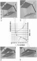
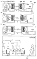
- FIG. 1 is a schematic configuration diagram of a wireless power supply system according to a first embodiment. It is the figure which showed the measurement result of the insertion loss at the time of changing the distance C between a feeding resonance coil and a receiving resonance coil. It is explanatory drawing explaining the power transmission efficiency at the time of changing the distance C between a feeding resonance coil and a receiving resonance coil with the light emission condition of blue LED. It is explanatory drawing of the wireless power supply system which concerns on Embodiment 1.
- FIG. It is a schematic block diagram of the wireless power supply system which concerns on Example 2.
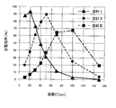
- FIG. 1 It is explanatory drawing explaining the distance C from which the power transmission efficiency becomes the maximum when changing the distance A between a feeding coil and a feeding resonance coil, and the distance B between a receiving resonance coil and a receiving coil. It is explanatory drawing of the wireless power supply system which concerns on Embodiment 2. FIG. It is explanatory drawing of the wireless power supply system which concerns on Embodiment 3. FIG.
- the wireless power supply system 101 resonates the power feeding resonator 102 and the power receiving resonator 103 so that the power transmitted as magnetic field energy is equal to or higher than a predetermined effective power.
- the positional relationship (distance C) between the resonator 102 and the power receiving resonator 103 is a power supply range F.
- the power feeding resonator 102 and the power receiving resonator 103 are, for example, a resonator using a coil, and examples thereof include spiral type, solenoid type, and loop type coils.
- Resonance means that the power feeding resonator 102 and the power receiving resonator 103 are tuned at the resonance frequency (for example, power from the AC power source 106 has the same frequency as the resonance frequency of the power feeding resonator 102 and the power receiving resonator 103. Is realized by output).
- the predetermined active power refers to power required on the power receiving resonator 103 side, and is a value set by desired power (for example, power required to move the power receiving unit 109).
- the positional relationship between the power feeding resonator 102 and the power receiving resonator 103 is set so that the coil surface of the coil used in the power feeding resonator 102 and the coil surface of the coil used in the power receiving resonator 103 are not orthogonal to each other. This is the linear distance between the coil surfaces in this case (indicated by the distance C in FIG. 1).
- the power supply range F is a range in which power greater than a predetermined active power is transmitted (in FIG. 1, a range where the distance C satisfies Y to Y ′).
- the positional relationship between the power feeding resonator 102 and the power receiving resonator 103 is set so that the power transmitted as magnetic field energy is greater than or equal to a predetermined effective power by resonating the power feeding resonator 102 and the power receiving resonator 103.
- predetermined active power can be transmitted only to the power supply range F that holds the positional relationship.
- the power receiving resonator 103 is out of the power supply range F, no power is transmitted.
- a wireless power supply system 1 shown in FIG. 2 is a system including a power feeding resonator 2 and a power receiving resonator 3, and transmits power from the power feeding resonator 2 to the power receiving resonator 3 as magnetic field energy.
- the power supply resonator 2 includes a power supply coil 4 and a power supply resonance coil 5 therein.
- the feeding coil 4 is connected to an AC power source 6 (power supply unit).
- the power receiving resonator 3 includes a power receiving coil 7 and a power receiving resonance coil 8 therein. And the receiving coil 7 is connected to blue LED9 (electric power receiving part).
- the AC power supply 6 outputs power at 16 MHz, which is the same frequency as the resonance frequency of the power supply resonance coil 5 and the power reception resonance coil 8. Therefore, the power supply resonance coil 5 and the power reception resonance coil 8 resonate at a resonance frequency of 16 MHz. In this embodiment, 0.5 W of electric power is output from the AC power source 6.
- the blue LED 9 is a diode that emits blue light mainly made of gallium nitride.
- the blue LED 9 emits blue light when power of 0.35 W or more, which is effective power necessary for light emission, is input.
- the blue LED 9 is configured not to emit light when a power less than an effective power of 0.35 W is input.
- the power supply coil 4 plays a role of supplying electric power obtained from the AC power source 6 to the power supply resonance coil 5 by electromagnetic induction.
- the power supply coil 4 is formed of a coil having a coil diameter of 80 mm ⁇ in which a rectangular copper wire (with an insulating coating) having a side of 2 mm is wound once.
- the power receiving coil 7 plays a role of outputting electric power transmitted as magnetic field energy from the power supply resonance coil 5 to the power reception resonance coil 8 to the blue LED 9 by electromagnetic induction. Similar to the power supply coil 4, the power receiving coil 7 is formed by a coil having a coil diameter of 80 mm ⁇ formed by winding a rectangular copper wire (with an insulating film) having a side of 2 mm once.
- the power receiving coil 7 is electrically connected to the blue LED 9, and the energy moved to the power receiving coil 7 by electromagnetic induction is output to the blue LED 9 as electric power.
- the power supply resonance coil 5 and the power reception resonance coil 8 are each an LC resonance circuit and play a role of creating a magnetic field resonance state.
- the capacitor component of the LC resonance circuit is realized by an element, but may be realized by a stray capacitance with both ends of the coil being opened.
- the power supply resonance coil 5 and the power reception resonance coil 8 are both formed of a coil having a coil inner diameter of 100 mm ⁇ and a coil outer diameter of 124 mm ⁇ obtained by winding a rectangular copper wire (with an insulating film) with a side of 2 mm three times. Further, since the power supply resonance coil 5 and the power reception resonance coil 8 need to have the same resonance frequency f determined by (Equation 1), the resonance frequency is set to 16 MHz. In addition, in order to make the resonance frequency the same, it does not necessarily need to be the same shape.
- the distance between the inner diameter of the feeding coil 4 and the inner diameter of the feeding resonance coil 5 is set to 10 mm, and the printed resonator is arranged as the feeding resonator 2 on the same plane substrate.
- the arrangement of the feeding coil 4 and the feeding resonance coil 5 may be any distance and arrangement that can generate electromagnetic induction.
- the distance between the inner diameter of the power receiving coil 7 and the inner diameter of the power receiving resonance coil 8 is set to 10 mm, and the power receiving resonator 3 is printed on the same plane substrate.
- the arrangement with the resonance coil 8 may be any distance and arrangement that can generate electromagnetic induction.
- a magnetic field resonance state can be created between the power supply resonance coil 5 and the power reception resonance coil 8. .
- electric power can be transmitted from the power supply resonance coil 5 to the power reception resonance coil 8 as magnetic field energy.
- the distance between the power supply resonance coil 5 and the power reception resonance coil 8 is C, and the positional relationship between the power supply resonance coil 5 of the power supply resonator 2 and the power reception resonance coil 8 of the power reception resonator 3 is expressed as follows. It arrange
- the reason why the distance C between the power supply resonance coil 5 and the power reception resonance coil 8 is set to 100 mm will be described below.
- the power supply coil 4 and the feeding resonance coil 5 are fixed to the same substrate, and the receiving resonance coil 8 and the receiving coil 7 are fixed to the same substrate.
- a change in power transmission efficiency when the distance C between the power supply resonance coil 5 and the power reception resonance coil 8 varies will be described.
- the power supply coil 4 is connected to the output terminal of a network analyzer (manufactured by Agilent Technologies) instead of the AC power supply 6, and the power receiving coil 7 is connected to the network instead of the blue LED 9.
- the horizontal axis is the transmission frequency
- the vertical axis is the insertion loss “S21”.
- the horizontal axis of the graph is described as distance C
- the vertical axis is described as power transmission efficiency.
- the transmission efficiency refers to the ratio of the power output to the power receiving unit to the power supplied to the power feeding resonator. That is, energy transfer efficiency when electric power is transmitted from the power supply resonator to the power reception resonator.
- the insertion loss “S21” represents a signal that passes through the input terminal when the signal is input from the output terminal, and is displayed in decibels. The larger the numerical value, the higher the power transmission efficiency. That is, the higher the insertion loss “S21”, the higher the ratio (power transmission efficiency) of the power output to the blue LED 9 as the power receiving unit to the power supplied to the power feeding resonator 2.
- FIG. 3A shows the measurement result of the insertion loss “S21” when the distance C is 37 mm.
- FIG. 3C shows the measurement result of the insertion loss “S21” when the distance C is 70 mm.
- FIG. 3E shows the measurement result of the insertion loss “S21” when the distance C is 150 mm.
- the transmission frequency at which the transmitted magnetic field energy reaches a peak is near the resonance frequency (in this embodiment, 16 MHz).
- the resonance frequency in this embodiment, 16 MHz.
- C 37 mm, 50 mm, 70 mm
- “S21” Separation is confirmed at the transmission frequency having the maximum value, and the value of “S21” becomes low near the resonance frequency. That is, it can be seen that when the distance C between the power supply resonance coil 5 and the power reception resonance coil 8 is reduced to some extent, the power transmission efficiency is reduced in the resonance frequency band as shown in FIG.
- the distance C between the power supply resonance coil 5 and the power reception resonance coil 8 is set to 100 mm in the resonance frequency (16 MHz) band between the power supply resonance coil 5 and the power reception resonance coil 8. This is to maximize the power transmission efficiency so that the effective power necessary for the light emission of the blue LED 9 is sufficiently transmitted.
- the distance C is set to 100 mm.
- the distance C is a distance where the power transmission efficiency is 70% or more. Good.
- the distance C between 88 mm and 105 mm is referred to as a power supply range in which effective power of 0.35 W or more necessary for light emission of the blue LED 9 can be transmitted.
- the power (0.5 W) supplied from the AC power source 6 to the power feeding coil 4 is fed through the electromagnetic induction between the power feeding coil 4 and the power feeding resonance coil 5.
- Power is transmitted with a power transmission efficiency of 74% using the magnetic field resonance state between the resonance coil 5 and the power reception resonance coil 8, and the blue LED 9 emits light through electromagnetic induction between the power reception resonance coil 8 and the power reception coil 7.
- the required effective power is output with a value of 0.35 W or more.
- blue LED9 which acquired effective electric power light-emits blue.
- the change in power transmission efficiency when the distance C between the power supply resonance coil 5 and the power reception resonance coil 8 is changed is expressed as the light emission condition of the blue LED 9 ( The operation will be described in comparison.
- the AC power supply 6 outputs 0.5 W of power at 16 MHz, which is the same frequency as the resonance frequency of the power supply resonance coil 5 and the power reception resonance coil 8.
- the power transmission efficiency needs to be 70% or more. When the power transmission efficiency is less than 70%, no light is emitted.
- the transmission efficiency is 70% or more (effective power 0) in the resonance frequency (16 MHz) band.
- the power transmission efficiency is less than 70% (effective power less than 0.35 W), and the blue LED 9 does not emit light. That is, it can be seen that there is actually a power supply range that is a range in which power greater than or equal to a predetermined active power is transmitted, and the present invention can be sufficiently realized by the existence of the power supply range.
- the power feeding resonator 2 and the power receiving resonator 3 are tuned at a resonance frequency of 16 MHz, and magnetic resonance occurs between the power feeding resonator 2 and the power receiving resonator 3.
- the power (0.5 W) supplied from the AC power source 6 can be wirelessly transmitted from the power feeding resonator 2 to the power receiving resonator 3 as magnetic field energy.
- the blue LED 9 emits blue light when power of 0.35 W or more, which is effective power necessary for light emission, is input, and does not emit light when power less than 0.35 W is input. It is configured.
- the distance C between the power supply resonance coil 5 of the power supply resonator 2 and the power reception resonance coil 8 of the power reception resonator 3 is output to the blue LED 9 for the power supplied to the power supply resonator 2 in the band of the resonance frequency of 16 MHz.
- the power ratio (power transmission efficiency) is 70% or more, that is, 100 mm, which is between 88 mm and 105 mm, so that 0.35 W or more, which is effective power necessary for light emission of the blue LED 9, is output. It is set.
- the power receiving resonator 3 receives an effective power of 0.35 W or more and outputs the effective power to the blue LED 9 to emit light. be able to.
- the blue LED 9 emits light only when the power supply resonance coil 5 of the power supply resonator 2 and the power reception resonance coil 8 of the power reception resonator 3 are in a positional relationship, that is, when the distance C is set between 88 mm and 105 mm.
- the blue LED 9 can be made to emit light by outputting the effective power necessary for the above.
- the positional relationship between the power supply resonance coil 5 of the power supply resonator 2 and the power reception resonance coil 8 of the power reception resonator 3 so that the distance C is set between 88 mm and 105 mm By making the power receiving resonance coil 8 resonate, the electric power transmitted as the magnetic field energy can be made effective power (0.35 W) or more. For this reason, active power can be transmitted as the power supply range only when the power feeding resonator 2 and the power receiving resonator 3 are placed in the above positional relationship.
- electric power is transmitted from the feed coil 4 to the feed resonance coil 5 by using electromagnetic induction between the feed coil 4 and the feed resonance coil 5 without creating a magnetic resonance state. be able to.
- electric power can be transmitted from the power receiving resonance coil 8 to the power receiving coil 7 by using electromagnetic induction between the power receiving resonance coil 8 and the power receiving coil 7 without creating a magnetic field resonance state. This eliminates the need for tuning at the resonance frequency between the power supply coil 4 and the power supply resonance coil 5 and between the power reception resonance coil 8 and the power reception coil 7, thereby simplifying the design.
- the transmission efficiency decreases when the distance between the power feeding resonator and the power receiving resonator is greater than the peak point.
- the power transmission efficiency refers to the ratio of the power output from the power receiving resonator to the power supplied to the power feeding resonator.
- the wireless power supply system 201 is a wireless power supply system that utilizes a change in power transmission efficiency when the positional relationship between the power feeding resonator and the power receiving resonator is changed.
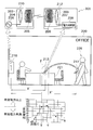
- FIG. 5 is an explanatory diagram of the wireless power supply system 201 according to the first embodiment.
- a wireless power supply system 201 illustrated in FIG. 5 includes a power transmission device 210 hung on a wall of an office 220 and a power reception device such as a mobile phone 212 placed on a desk 221.
- the power transmission device 210 includes an AC power supply 206 and a power supply resonator 202, and the power supply resonator 202 includes a power supply coil 204 and a power supply resonance coil 205 connected to the AC power supply 206.
- the power receiving device such as the mobile phone 212 includes a power receiving unit 209 and a power receiving resonator 203, and the power receiving resonator 203 includes a power receiving coil 207 and a power receiving resonant coil 208 connected to the power receiving unit 209.
- the mobile phone 212 is placed on the desk 221 separated from the power transmission apparatus 210 by a distance X ′′ from the power transmission apparatus 210 and separated from the power transmission apparatus 210 by a distance X ′. It will be described as being moved to a state.
- the feeding coil 204 plays a role of supplying power obtained from the AC power source 206 to the feeding resonance coil 205 by electromagnetic induction.
- A be the distance between the feeding coil 204 and the feeding resonance coil 205.
- the arrangement of the power feeding coil 204 and the power feeding resonance coil 205 may be any distance and arrangement that can generate electromagnetic induction.
- the power receiving coil 207 plays a role of outputting the power transmitted as magnetic field energy from the power supply resonance coil 205 to the power reception resonance coil 208 to the power reception unit 209 by electromagnetic induction.
- B is a distance between the power receiving resonance coil 208 and the power receiving coil 207.
- positioning of the receiving coil 207 and the receiving resonance coil 208 should just be the distance and arrangement
- the power receiving coil 207 is electrically connected to the power receiving unit 209, and the energy moved to the power receiving coil 207 by electromagnetic induction is output to the power receiving unit 209 as electric power.
- the power supply resonance coil 205 and the power reception resonance coil 208 are each an LC resonance circuit and play a role of creating a magnetic field resonance state.
- the capacitor component of the LC resonance circuit is realized by an element, but may be realized by a stray capacitance with both ends of the coil being opened.
- f determined by (Equation 1) is the resonance frequency.
- the power supply resonance coil 205 and the power reception resonance coil 208 need to have the same resonance frequency f determined by (Equation 1).
- the resonance frequency f it does not necessarily need to be the same shape.
- a magnetic field resonance state can be created between the power supply resonance coil 205 and the power reception resonance coil 208.
- a magnetic field resonance state is created in a state where the power supply resonance coil 205 resonates, power can be transmitted from the power supply resonance coil 205 to the power reception resonance coil 208 as magnetic field energy.
- the distance between the power supply resonance coil 205 of the power transmission apparatus 210 and the power reception resonance coil 208 of the mobile phone 212 is C, as shown in FIG.
- the mobile phone 212 (power receiving resonance coil 208) moved onto the desk 221 is located at a position separated from the power transmission device 210 (power feeding resonance coil 205) by a distance X ′′. ) At a distance X ′ apart.
- the AC power source 206 outputs power at the same frequency as the resonance frequency of the power supply resonance coil 205 and the power reception resonance coil 208.
- the power receiving unit 209 includes a rectifier circuit connected to the power receiving coil 207, a charge control device connected to the rectifier circuit, and a battery connected to the charge control device.
- the power receiving unit 209 plays a role of storing the power transmitted from the power receiving coil 207 in the battery via the rectifier circuit and the charging control device.
- Examples of the battery include a nickel metal hydride battery, a lithium ion battery, and other secondary batteries.
- the charging control device plays a role of controlling charging when active power necessary for charging the battery is input. Therefore, the battery is configured not to be charged when power less than the effective power is input.
- the ratio (power transmission efficiency) of the power output from the power receiving resonator 203 to the power supplied to the power feeding resonator 202 is 70% or more, the effective power necessary for charging the battery is input ( (See FIG. 5).
- the power supplied from the AC power source 206 is electromagnetic induction between the power supply coil 204 and the power supply resonance coil 205, and between the power supply resonance coil 205 and the power reception resonance coil 208.
- the distance C between the power supply resonance coil 205 and the power reception resonance coil 208 of the power transmission device 210 becomes X ′ through power transmission using the magnetic field resonance state and electromagnetic induction between the power reception resonance coil 208 and the power reception coil 207.
- the power is received by the power receiving unit 209 of the mobile phone 212 placed on the desk 221.
- the person 226 holds the power C so that the distance C between the power supply resonance coil 205 and the power reception resonance coil 208 of the power transmission device 210 is X ′′, no power is supplied to the mobile phone 212.
- the battery of the power receiving unit 209 of the mobile phone 212 placed on the desk 221 is charged in this way because the distance C between the power supply resonance coil 205 and the power reception resonance coil 208 of the power transmission device 210 is This is because, in the resonance frequency band, the distance X ′ is set to a power transmission efficiency of 70% or more so that the effective power necessary for charging the battery of the mobile phone 212 can be secured.
- the distance C X ′, but the distance C may be a distance at which the power transmission efficiency is 70% or more.
- the distance C between Y and Y ′ is referred to as a power supply range F in which effective power necessary for charging the battery of the power receiving unit 209 can be transmitted.
- the battery of the power receiving unit 209 of the mobile phone 212 is not charged because the power supply resonance coil 205 of the power transmission device 210 and the power reception resonance coil of the mobile phone 212 are not charged.
- the distance C to 208 is set to a distance X ′′ in which the effective power necessary for charging the battery of the power receiving unit 209 of the mobile phone 212 cannot be secured (the transmission efficiency is less than 70%) in the resonance frequency band. That is, when the person 226 has the mobile phone 212 as shown in Fig. 5, since the mobile phone 212 is outside the power supply range F, the battery of the mobile phone 212 is Is not charged.
- charging cannot be performed when the mobile phone 212 is outside the power supply range F, but charging is possible when the mobile phone 212 is brought into the power supply range F. That is, the battery of the mobile phone 212 can be charged only in a limited range (power supply range F).
- the power supply range F is set to the effective power necessary for charging the battery of the mobile phone 212 in the resonance frequency band.
- the distance is set within the range of Y to Y ′ so that the power transmission efficiency that can secure power is 70% or more.
- the mobile phone 212 is placed so that the distance C between the power supply resonance coil 205 of the power transmission device 210 and the power reception resonance coil 208 of the mobile phone 212 falls within the range of the distances Y to Y ′ (power supply range F). 221 is moved over.
- the power supplied from the AC power supply 206 is transmitted and received using the electromagnetic induction between the power supply coil 204 and the power supply resonance coil 205 and the magnetic resonance state between the power supply resonance coil 205 and the power reception resonance coil 208.
- the electric power transmitted from the power receiving coil 207 via the electromagnetic induction between the coil 208 and the power receiving coil 207 is supplied to the battery as effective power necessary for charging the battery via the rectifier circuit and the charging control device provided in the power receiving unit 209. It is charged.
- the battery provided in the power receiving unit 209 can be charged only when a power receiving device such as the mobile phone 212 is placed in the power supply range F shown in FIG.
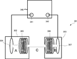
- Example 2 Hereinafter, a wireless power supply system 301 according to the second embodiment will be described with reference to FIGS. 6 and 7.
- the distance A between the power supply coil 304 and the power supply resonance coil 305 and the distance B between the power reception resonance coil 308 and the power reception coil 307 in the wireless power supply system 301 can be freely set by changing at least one of the above.
- a wireless power supply system 301 shown in FIG. 6 is a system including a power feeding resonator 302 and a power receiving resonator 303, and transmits power from the power feeding resonator 302 to the power receiving resonator 303 as magnetic field energy.
- the power feeding resonator 302 includes a power feeding coil 304 and a power feeding resonance coil 305.
- the power receiving resonator 303 includes a power receiving coil 307 and a power receiving resonance coil 308 therein.
- the power feeding coil 304 and the power receiving coil 307 are formed by a coil having a coil diameter of 100 mm ⁇ obtained by winding a circular copper wire (with an insulating coating) having a wire diameter of 1 mm ⁇ once.
- the power supply coil 304 is connected to an output terminal 341 of a network analyzer 340 (manufactured by Agilent Technologies) instead of the AC power supply, and the power receiving coil 307 is connected to an input terminal 342 of the network analyzer.
- the network analyzer 340 can output AC power from the output terminal 341 to the feeding coil 304 at an arbitrary frequency. Further, the network analyzer 340 can measure the power input from the power receiving coil 307 to the input terminal 342. Furthermore, the network analyzer 340 can measure power transmission efficiency as shown in FIG.
- the power supply resonance coil 305 and the power reception resonance coil 308 are each an LC resonance circuit, and the power supply resonance coil 305 and the power reception resonance coil 308 are made by winding a circular copper wire (with an insulating film) with a wire diameter of 1 mm ⁇ three times in a solenoid shape Formed by a coil having a diameter of 100 mm. Further, since the power supply resonance coil 305 and the power reception resonance coil 308 need to have the same resonance frequency f determined by (Equation 1), the resonance frequency is set to 15 MHz.
- the distance A between the power feeding coil 304 and the power feeding resonance coil 305 is the distance between the coil surfaces when the coil surface of the power feeding coil 304 and the coil surface of the power feeding resonance coil 305 are arranged so as not to be orthogonal to each other. It means the straight line distance.
- the distance B between the power receiving resonance coil 308 and the power receiving coil 307 is the distance between the coil surfaces when the coil surface of the power receiving coil 307 and the coil surface of the power receiving resonance coil 308 are arranged so as not to be orthogonal to each other. This means the linear distance.
- the distance C between the power supply resonance coil 305 and the power reception resonance coil 308 is the distance between the coil surfaces when the coil surface of the power supply resonance coil 305 and the coil surface of the power reception resonance coil 308 are arranged so as not to be orthogonal to each other.
- the straight line distance between the power supply resonance coil 305 and the power reception resonance coil 308 is the distance between the coil surfaces when the coil surface of the power supply resonance coil 305 and the coil surface of the power reception resonance coil 308 are arranged so as not to be orthogonal to each other.
- the wireless power supply system 301 when the wireless power supply system 301 is used and the distance A between the power supply coil 304 and the power supply resonance coil 305 and the distance B between the power reception resonance coil 308 and the power reception coil 307 are changed.
- a measurement result of the network analyzer 340 for the distance C between the power supply resonance coil 305 and the power reception resonance coil 308 that maximizes the power transmission efficiency will be described with reference to FIG.
- the horizontal axis is distance C
- the vertical axis is power transmission efficiency.
- the power supply resonance coil 305 and the power reception resonance that maximize power transmission efficiency are changed. It can be seen that the distance C between the coil 308 changes.
- the wireless power supply system 401 according to Embodiment 2 changes at least one of the distance A between the power supply coil 404 and the power supply resonance coil 405 and the distance B between the power reception resonance coil 408 and the power reception coil 407.
- the wireless power supply system utilizes the fact that the distance C between the power supply resonance coil 405 and the power reception resonance coil 408 that maximizes the power transmission efficiency can be set freely.
- the description of the same configuration as that of the first embodiment is omitted.
- FIG. 8 is an explanatory diagram of the wireless power supply system 401 according to the second embodiment.
- a wireless power supply system 401 illustrated in FIG. 8 includes a power transmission device 410 hung on the wall of an office 420 and a power receiving device such as a mobile phone 412 placed on a desk 421, as in the first embodiment.
- the power transmission device 410 includes an AC power source 406, a power feeding resonator 402, and a regulator 418.
- the power feeding resonator 402 includes a power feeding coil 404 and a power feeding resonance coil 405 connected to the AC power source 406.
- the adjuster 418 can variably adjust the distance A between the power supply coil 404 and the power supply resonance coil 405.
- the mobile phone 412 includes a power receiving unit 409 and a power receiving resonator 403, and the power receiving resonator 403 includes a power receiving coil 407 and a power receiving resonant coil 408 connected to the power receiving unit 409.
- the distance B is fixed to a constant value.
- distance B is fixed to a constant value.
- the wireless power supply system 401 If the wireless power supply system 401 is used, at least one of the distance A between the power supply coil 404 and the power supply resonance coil 405 and the distance B between the power reception resonance coil 408 and the power reception coil 407 can be freely set.
- a power supply range for example, power supply range G, power supply range H, power supply range I
- the chargeable power supply range can be set freely.
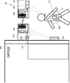
- a wireless power supply system 601 may be employed in a non-contact type IC card for entering an office.
- a card reader 610 including a power supply resonator 602 connected to an AC power source 606 is installed on the side wall of the door 631 of the office 630, and power reception resonance connected to an IC chip 609 for personal identification.
- An IC card 611 provided with a device 603 is prepared. Then, as shown in FIG. 9, the power supply range P in which the power transmission efficiency is equal to or higher than the effective power necessary for reading the IC chip 609 is set near the front of the door 631.
- the wireless power supply system according to the present invention can be applied to a power supply device such as a work robot or an electric vehicle.
- a power supply device such as a work robot or an electric vehicle.
- the power supply range that is equal to or greater than the effective power necessary for the operation of the work robot is determined as the work area, so that the operation when the work robot leaves the work area can be stopped. Thereby, even if the work robot is out of the work area for some reason, the power supply to the work robot can be stopped and the operation can be stopped, so that the safety of the work robot can be improved.
- the resonance frequency of the power supply resonance coil 205 on the power transmission device 210 side and the resonance frequency of the power reception resonance coil 208 on the mobile phone 212 side are set to the same value, the power supply resonance coil 205 to the mobile phone 212
- power can be transmitted to the power receiving resonance coil 208 as magnetic field energy, the present invention is not limited to this.
- the resonance frequency of the power reception resonance coil included in the mobile phone is set to 15 MHz
- the resonance frequency of the power reception resonance coil included in the personal computer is set to 16 MHz
- the resonance frequency of the power reception resonance coil included in the tablet PC is set to 14 MHz.
- a power supply resonance coil having resonance frequencies of 14 MHz, 15 MHz, and 16 MHz is prepared on the power transmission device side, and the power transmission frequency of the AC power transmitted from the AC power supply to the power supply resonance coil is freely converted to 14 MHz, 15 MHz, or 16 MHz.
- power may be individually transmitted as magnetic field energy via the power supply resonance coil and the power reception resonance coil that resonate.
Landscapes
- Engineering & Computer Science (AREA)
- Computer Networks & Wireless Communication (AREA)
- Power Engineering (AREA)
- Signal Processing (AREA)
- Charge And Discharge Circuits For Batteries Or The Like (AREA)
- Near-Field Transmission Systems (AREA)
Priority Applications (4)
| Application Number | Priority Date | Filing Date | Title |
|---|---|---|---|
| US13/983,085 US9461506B2 (en) | 2011-02-04 | 2012-02-03 | Wireless power-supply system |
| EP12741907.5A EP2672607A4 (de) | 2011-02-04 | 2012-02-03 | Drahtloses stromversorgungssystem |
| CN2012800076103A CN103370850A (zh) | 2011-02-04 | 2012-02-03 | 无线电力供给系统 |
| KR1020137023263A KR20140051140A (ko) | 2011-02-04 | 2012-02-03 | 무선 전력 공급 시스템 |
Applications Claiming Priority (2)
| Application Number | Priority Date | Filing Date | Title |
|---|---|---|---|
| JP2011022920A JP2012165527A (ja) | 2011-02-04 | 2011-02-04 | 無線電力供給システム |
| JP2011-022920 | 2011-02-04 |
Publications (1)
| Publication Number | Publication Date |
|---|---|
| WO2012105675A1 true WO2012105675A1 (ja) | 2012-08-09 |
Family
ID=46602875
Family Applications (1)
| Application Number | Title | Priority Date | Filing Date |
|---|---|---|---|
| PCT/JP2012/052449 Ceased WO2012105675A1 (ja) | 2011-02-04 | 2012-02-03 | 無線電力供給システム |
Country Status (7)
| Country | Link |
|---|---|
| US (1) | US9461506B2 (de) |
| EP (1) | EP2672607A4 (de) |
| JP (2) | JP2012165527A (de) |
| KR (1) | KR20140051140A (de) |
| CN (1) | CN103370850A (de) |
| TW (1) | TW201244320A (de) |
| WO (1) | WO2012105675A1 (de) |
Cited By (1)
| Publication number | Priority date | Publication date | Assignee | Title |
|---|---|---|---|---|
| EP2985861A4 (de) * | 2013-02-28 | 2017-01-11 | Nitto Denko Corporation | Drahtlose leistungsübertragungsvorrichtung, versorgungsstromsteuerungsverfahren für drahtlose leistungsübertragungsvorrichtung und herstellungsverfahren für drahtlose leistungsübertragungsvorrichtung |
Families Citing this family (10)
| Publication number | Priority date | Publication date | Assignee | Title |
|---|---|---|---|---|
| JP5968596B2 (ja) * | 2011-04-11 | 2016-08-10 | 日東電工株式会社 | 無線電力供給システム |
| JP6144176B2 (ja) * | 2013-10-15 | 2017-06-07 | 日東電工株式会社 | 磁界空間を形成可能な無線電力伝送装置及びその形成方法 |
| JP6094531B2 (ja) * | 2014-06-02 | 2017-03-15 | 中国電力株式会社 | 仮想画像を利用した作業支援システム |
| US10084343B2 (en) | 2014-06-13 | 2018-09-25 | Empire Technology Development Llc | Frequency changing encoded resonant power transfer |
| US10069324B2 (en) | 2014-09-08 | 2018-09-04 | Empire Technology Development Llc | Systems and methods for coupling power to devices |
| US10320228B2 (en) * | 2014-09-08 | 2019-06-11 | Empire Technology Development Llc | Power coupling device |
| CN106300471A (zh) * | 2015-05-29 | 2017-01-04 | 青岛众海汇智能源科技有限责任公司 | 一种无线充电方法及无线发射端 |
| JP6663250B2 (ja) * | 2016-02-26 | 2020-03-11 | 株式会社ジャパンディスプレイ | 表示装置 |
| CN107104517A (zh) * | 2017-06-05 | 2017-08-29 | 三峡大学 | 一种能实现稳定电压输出的mcr‑wpt电路及其控制方法 |
| US10283952B2 (en) | 2017-06-22 | 2019-05-07 | Bretford Manufacturing, Inc. | Rapidly deployable floor power system |
Citations (4)
| Publication number | Priority date | Publication date | Assignee | Title |
|---|---|---|---|---|
| JP2007104868A (ja) * | 2005-10-07 | 2007-04-19 | Toyota Motor Corp | 車両用充電装置、電気機器及び車両用非接触充電システム |
| JP2010124522A (ja) | 2008-11-17 | 2010-06-03 | Toyota Central R&D Labs Inc | 給電システム |
| JP2010239777A (ja) | 2009-03-31 | 2010-10-21 | Fujitsu Ltd | 無線電力装置、無線電力受信方法 |
| JP2010239769A (ja) | 2009-03-31 | 2010-10-21 | Fujitsu Ltd | 無線電力供給システム |
Family Cites Families (12)
| Publication number | Priority date | Publication date | Assignee | Title |
|---|---|---|---|---|
| CN101197507A (zh) * | 2006-12-06 | 2008-06-11 | 北京中电华大电子设计有限责任公司 | 无线电源装置及电路 |
| US20090160261A1 (en) * | 2007-12-19 | 2009-06-25 | Nokia Corporation | Wireless energy transfer |
| US8878393B2 (en) | 2008-05-13 | 2014-11-04 | Qualcomm Incorporated | Wireless power transfer for vehicles |
| JP4743244B2 (ja) * | 2008-09-18 | 2011-08-10 | トヨタ自動車株式会社 | 非接触受電装置 |
| JP5262785B2 (ja) | 2009-02-09 | 2013-08-14 | 株式会社豊田自動織機 | 非接触電力伝送装置 |
| JP2010183813A (ja) * | 2009-02-09 | 2010-08-19 | Toyota Industries Corp | 共鳴型非接触充電システム |
| JP2010233394A (ja) * | 2009-03-27 | 2010-10-14 | Aisin Aw Co Ltd | 受電支援装置、受電支援方法、及び受電支援プログラム |
| JP5515368B2 (ja) * | 2009-03-31 | 2014-06-11 | 富士通株式会社 | 無線電力供給方法及び無線電力供給システム |
| JP2010246348A (ja) * | 2009-04-09 | 2010-10-28 | Fujitsu Ten Ltd | 受電装置、及び送電装置 |
| JP4865001B2 (ja) * | 2009-04-13 | 2012-02-01 | 株式会社日本自動車部品総合研究所 | 非接触給電設備、非接触受電装置および非接触給電システム |
| TW201039528A (en) * | 2009-04-24 | 2010-11-01 | Darfon Electronics Corp | Energy transferring system and energy transferring side device |
| TWM381217U (en) | 2009-12-14 | 2010-05-21 | Micro Star Int Co Ltd | Inductive charging system capable of chagring automatically |
-
2011
- 2011-02-04 JP JP2011022920A patent/JP2012165527A/ja active Pending
-
2012
- 2012-02-03 TW TW101103561A patent/TW201244320A/zh unknown
- 2012-02-03 KR KR1020137023263A patent/KR20140051140A/ko not_active Withdrawn
- 2012-02-03 US US13/983,085 patent/US9461506B2/en not_active Expired - Fee Related
- 2012-02-03 EP EP12741907.5A patent/EP2672607A4/de not_active Withdrawn
- 2012-02-03 CN CN2012800076103A patent/CN103370850A/zh active Pending
- 2012-02-03 WO PCT/JP2012/052449 patent/WO2012105675A1/ja not_active Ceased
-
2015
- 2015-03-16 JP JP2015052552A patent/JP6025893B2/ja not_active Expired - Fee Related
Patent Citations (4)
| Publication number | Priority date | Publication date | Assignee | Title |
|---|---|---|---|---|
| JP2007104868A (ja) * | 2005-10-07 | 2007-04-19 | Toyota Motor Corp | 車両用充電装置、電気機器及び車両用非接触充電システム |
| JP2010124522A (ja) | 2008-11-17 | 2010-06-03 | Toyota Central R&D Labs Inc | 給電システム |
| JP2010239777A (ja) | 2009-03-31 | 2010-10-21 | Fujitsu Ltd | 無線電力装置、無線電力受信方法 |
| JP2010239769A (ja) | 2009-03-31 | 2010-10-21 | Fujitsu Ltd | 無線電力供給システム |
Non-Patent Citations (1)
| Title |
|---|
| See also references of EP2672607A4 |
Cited By (1)
| Publication number | Priority date | Publication date | Assignee | Title |
|---|---|---|---|---|
| EP2985861A4 (de) * | 2013-02-28 | 2017-01-11 | Nitto Denko Corporation | Drahtlose leistungsübertragungsvorrichtung, versorgungsstromsteuerungsverfahren für drahtlose leistungsübertragungsvorrichtung und herstellungsverfahren für drahtlose leistungsübertragungsvorrichtung |
Also Published As
| Publication number | Publication date |
|---|---|
| EP2672607A4 (de) | 2016-03-30 |
| CN103370850A (zh) | 2013-10-23 |
| JP2012165527A (ja) | 2012-08-30 |
| KR20140051140A (ko) | 2014-04-30 |
| US20140035385A1 (en) | 2014-02-06 |
| US9461506B2 (en) | 2016-10-04 |
| JP2015122956A (ja) | 2015-07-02 |
| JP6025893B2 (ja) | 2016-11-16 |
| EP2672607A1 (de) | 2013-12-11 |
| TW201244320A (en) | 2012-11-01 |
Similar Documents
| Publication | Publication Date | Title |
|---|---|---|
| JP6025893B2 (ja) | 無線電力供給システム | |
| US10523276B2 (en) | Wireless power receiver with multiple receiver coils | |
| JP5968596B2 (ja) | 無線電力供給システム | |
| US11770027B2 (en) | Wireless power transmission device | |
| US11722010B2 (en) | Wireless power transmission device | |
| TW201421848A (zh) | 無線電力傳送裝置 | |
| KR20120116802A (ko) | 중계기를 이용한 무선 전력 전송 시스템 및 무선 전력 수신기 | |
| JP2013240263A (ja) | 磁界空間の形成方法 | |
| US10879736B2 (en) | Wireless power transfer systems and methods using non-resonant power receiver | |
| KR20210129618A (ko) | 무선 전력 송수신 장치 | |
| CN105932789B (zh) | 变压器及电源板 | |
| JP2015213428A (ja) | 無線電力供給システム | |
| JP2013070491A (ja) | 無線空間給電システム | |
| CN110521081B (zh) | 使用非谐振电能接收器的无线电能传输系统和方法 | |
| KR101883655B1 (ko) | 무선 전력 수신기 및 그 제어 방법 | |
| KR20200106786A (ko) | 무선으로 전력을 송신하는 무선 전력 송신 장치 | |
| JP2018143064A (ja) | 送電装置 |
Legal Events
| Date | Code | Title | Description |
|---|---|---|---|
| 121 | Ep: the epo has been informed by wipo that ep was designated in this application |
Ref document number: 12741907 Country of ref document: EP Kind code of ref document: A1 |
|
| WWE | Wipo information: entry into national phase |
Ref document number: 2012741907 Country of ref document: EP |
|
| NENP | Non-entry into the national phase |
Ref country code: DE |
|
| ENP | Entry into the national phase |
Ref document number: 20137023263 Country of ref document: KR Kind code of ref document: A |
|
| WWE | Wipo information: entry into national phase |
Ref document number: 13983085 Country of ref document: US |