WO2012105806A2 - 네트워크 시스템 - Google Patents
네트워크 시스템 Download PDFInfo
- Publication number
- WO2012105806A2 WO2012105806A2 PCT/KR2012/000765 KR2012000765W WO2012105806A2 WO 2012105806 A2 WO2012105806 A2 WO 2012105806A2 KR 2012000765 W KR2012000765 W KR 2012000765W WO 2012105806 A2 WO2012105806 A2 WO 2012105806A2
- Authority
- WO
- WIPO (PCT)
- Prior art keywords
- node
- address
- local
- information
- flexible
- Prior art date
- Legal status (The legal status is an assumption and is not a legal conclusion. Google has not performed a legal analysis and makes no representation as to the accuracy of the status listed.)
- Ceased
Links
Images


Classifications
-
- H—ELECTRICITY
- H04—ELECTRIC COMMUNICATION TECHNIQUE
- H04L—TRANSMISSION OF DIGITAL INFORMATION, e.g. TELEGRAPHIC COMMUNICATION
- H04L45/00—Routing or path finding of packets in data switching networks
- H04L45/74—Address processing for routing
- H04L45/741—Routing in networks with a plurality of addressing schemes, e.g. with both IPv4 and IPv6
-
- H—ELECTRICITY
- H04—ELECTRIC COMMUNICATION TECHNIQUE
- H04W—WIRELESS COMMUNICATION NETWORKS
- H04W8/00—Network data management
- H04W8/26—Network addressing or numbering for mobility support
-
- H—ELECTRICITY
- H04—ELECTRIC COMMUNICATION TECHNIQUE
- H04L—TRANSMISSION OF DIGITAL INFORMATION, e.g. TELEGRAPHIC COMMUNICATION
- H04L45/00—Routing or path finding of packets in data switching networks
- H04L45/54—Organization of routing tables
-
- H—ELECTRICITY
- H04—ELECTRIC COMMUNICATION TECHNIQUE
- H04L—TRANSMISSION OF DIGITAL INFORMATION, e.g. TELEGRAPHIC COMMUNICATION
- H04L61/00—Network arrangements, protocols or services for addressing or naming
- H04L61/09—Mapping addresses
- H04L61/10—Mapping addresses of different types
- H04L61/103—Mapping addresses of different types across network layers, e.g. resolution of network layer into physical layer addresses or address resolution protocol [ARP]
-
- H—ELECTRICITY
- H04—ELECTRIC COMMUNICATION TECHNIQUE
- H04L—TRANSMISSION OF DIGITAL INFORMATION, e.g. TELEGRAPHIC COMMUNICATION
- H04L67/00—Network arrangements or protocols for supporting network services or applications
- H04L67/50—Network services
- H04L67/52—Network services specially adapted for the location of the user terminal
-
- H—ELECTRICITY
- H04—ELECTRIC COMMUNICATION TECHNIQUE
- H04W—WIRELESS COMMUNICATION NETWORKS
- H04W4/00—Services specially adapted for wireless communication networks; Facilities therefor
- H04W4/02—Services making use of location information
-
- H—ELECTRICITY
- H04—ELECTRIC COMMUNICATION TECHNIQUE
- H04W—WIRELESS COMMUNICATION NETWORKS
- H04W4/00—Services specially adapted for wireless communication networks; Facilities therefor
- H04W4/02—Services making use of location information
- H04W4/029—Location-based management or tracking services
-
- H—ELECTRICITY
- H04—ELECTRIC COMMUNICATION TECHNIQUE
- H04L—TRANSMISSION OF DIGITAL INFORMATION, e.g. TELEGRAPHIC COMMUNICATION
- H04L2101/00—Indexing scheme associated with group H04L61/00
- H04L2101/60—Types of network addresses
- H04L2101/604—Address structures or formats
-
- H—ELECTRICITY
- H04—ELECTRIC COMMUNICATION TECHNIQUE
- H04L—TRANSMISSION OF DIGITAL INFORMATION, e.g. TELEGRAPHIC COMMUNICATION
- H04L2101/00—Indexing scheme associated with group H04L61/00
- H04L2101/60—Types of network addresses
- H04L2101/69—Types of network addresses using geographic information, e.g. room number
-
- H—ELECTRICITY
- H04—ELECTRIC COMMUNICATION TECHNIQUE
- H04L—TRANSMISSION OF DIGITAL INFORMATION, e.g. TELEGRAPHIC COMMUNICATION
- H04L61/00—Network arrangements, protocols or services for addressing or naming
- H04L61/09—Mapping addresses
- H04L61/25—Mapping addresses of the same type
- H04L61/2503—Translation of Internet protocol [IP] addresses
- H04L61/2514—Translation of Internet protocol [IP] addresses between local and global IP addresses
Definitions
- the present invention relates to a network system, and more particularly, to a network system of a new structure for application to a future network.
- smartphones generally support WLAN and cellular networks simultaneously, so it is necessary to support handover independently for media.
- end-to-end delay needs to be considered for the transmission of real-time traffic such as voice / video over WLAN as well as cellular networks.
- Fifth, low power communication needs to be considered in consideration of a situation in which available power is limited.
- the current major problems of the Internet is to address the problem of overload and routing scalability of the meaning of the IP address.
- the problem of overloading the meaning of an IP address is a problem in which the current IP address refers to where and who.
- routing scalability is a problem that the routing table increases due to multi-homing, traffic engineering, and non-aggregatable address allocation.
- MANET independent and self-organizing network
- communication of internal nodes is also important, but information exchange with external network is also important, so it is necessary to consider the connection between MANET and external network.
- the present invention solves the problems of the prior art described above, and some embodiments of the present invention seek to provide a network system that enables the generation and management of a new concept of network address including location information of a node.
- a network address generation device for a node including a locator for defining the location information of the location where the node is located and the A network address is generated that includes the node identifier including the identification information.
- the data packet transmission method of the local global router is a node identifier of the transmitting node, a node identifier of the destination node, a flexible local address of the transmitting node and a local network of the transmitting node from the transmitting node.
- the method for managing a flexible address registers a flexible local address including a flexible local address of the node and node identifier information of the node from a node included in a local network in charge of a local global router.
- Receiving a request message And in response to receiving the registration request message of the flexible local address, the local global router storing the mapping relationship between the node identifier information of the node and the flexible local address of the node in a mapping table, wherein the flexible local address Is generated based on information of the locator of the node and the local global router.
- the method for managing a flexible address using a database system includes a node information of a node included in a local network that is in charge of the local global router and a flexible global address of the local global router from a local global router.
- the database system includes a node identifier information of the node and a local network including the node. And storing the mapping relationship of the flexible global addresses of the local global router in the mapping table.
- FIG. 1 is a view for explaining the concept of a flexible address operation according to an embodiment of the present invention.
- FIG. 2 is a diagram for describing a location information structure generated according to an embodiment of the present invention.
- 3A and 3B are views for explaining a locator structure according to an embodiment of the present invention.
- FIG. 4 is a view for explaining a data packet forwarding method according to an embodiment of the present invention.
- 5A to 5C are diagrams for describing a data packet forwarding method according to an embodiment of the present invention.
- 6A and 6B are diagrams for describing a configuration of a mapping table for LOC management.
- FIG. 7 is a diagram illustrating a LOC registration process of a FLA node in a network system according to an embodiment of the present invention.
- FIGS. 8A to 8D are diagrams for describing a process of querying locator information in a network system according to an embodiment of the present invention.
- FIG. 9 is a view for explaining a process of moving a FLA node according to an embodiment of the present invention.
- FIG. 10 is a diagram illustrating a routing method according to a location change of a FLA node in a network system according to an embodiment of the present invention.
- FIG. 11 is a diagram illustrating a method of changing a router according to a change of a location of a node in a network system according to an embodiment of the present invention.
- FIG. 12 is a view for explaining the configuration of the NCP according to an embodiment of the present invention.
- FIGS. 13A and 13B are diagrams for describing a configuration of a data transmission protocol according to an embodiment of the present invention.
- FIG. 14 is a diagram illustrating a geographical routing method on a network system according to an embodiment of the present invention.
- 15 is a view for explaining a problem of the greedy forwarding method.
- 16 is a diagram illustrating an improved greedy forwarding method in a network system according to an embodiment of the present invention.
- 17 is a diagram illustrating a procedure for setting an address by obtaining location information from a reference point according to an embodiment of the present invention.
- FIG. 18 is a diagram illustrating a network configuration for explaining an address setting procedure of a terminal for which location information measurement is impossible in a wireless multi-hop network environment according to the present invention.
- 19 is a diagram illustrating an address setting procedure within one hop in a wireless multi-hop network environment according to the present invention.
- 20 is a diagram illustrating an address setting procedure within two hops in a wireless multi-hop network environment according to the present invention.
- 21 is an exemplary diagram in which a range of a destination is expressed by a cube using a range field applied to the present invention.
- FIG. 22 is an explanatory diagram representing a geographical address in an IPv6 header applied to the present invention.
- 23 is a datagram with an extended header applied to the present invention.
- a link is a communication facility or medium that allows nodes to communicate at the link layer.
- An interface represents a node's connection to a link.
- a backbone network represents an existing internet legacy of numerous site networks, ISPs, and network providers.
- a local network represents a group of hosts and routers that share a common communication line or wireless link.
- Locators represent locations of nodes within a network.
- the absolute locator represents area range information from the latitude, longitude, altitude, and absolute position of the point where the user node is located.
- Relative locators represent relative distances and ranges from a reference point.
- Flexible global address (FGA) represents the address of a node within the backbone network.
- Flexible local address (FLA) represents the address of a node in the local network.
- the flexible address (FA) represents a flexible global address or a flexible local address.
- the node identifier (NID) represents a globally unique identifier composed of user, node, interface and other information. For example, the NID may be specified by the MAC address of the node, the serial number, information of the processor included in the node, or bandwidth information.
- a FLA-FGA Router (LGR) represents a router located between a local network and a backbone network.
- the FLA Router (FR) represents a router located between the LGR and the nodes in the local network.
- a backbone router (BR) represents a router located between LGRs in a backbone network.
- NFS NFS (NID-FA Systems) represents a central database system that includes NID and FA. Inbound traffic represents traffic destined for the local network from the backbone network. Outbound traffic represents traffic destined for the backbone network from the local network.
- the FLA node represents a node using the FLA.
- ID can be composed of unique numbers, letters or symbols to distinguish users or devices, and can be configured to have a hierarchical structure.
- ID and locator on the same layer. This method has both ID and locator information in the address field. Similar to the fact that the current IP address consists of a network prefix and an interface ID, it can be distinguished by a specific length ID and a locator.
- translation or tunneling may be required between the local network and the backbone network.
- mapping one address in the local network to one address in the backbone network is the same method as current NAT.
- mapping a plurality of addresses in the local network to one address in the backbone network is the same method as the current NAT-PT.
- the address of the backbone network is determined according to the service or function used by the nodes of the local network.
- mapping of a plurality of addresses in a local network to a plurality of addresses in a backbone network is a case where many-to-one conversion and one-to-many conversion are used simultaneously.
- Tunneling can be used in the local network and the backbone network. Tunneling can be classified into four cases as follows.
- one tunneling address is used for one address.
- tunneling addresses are used for one address, and the tunneling address is determined according to a service or a function used for one address.
- multiple tunneling addresses are used for multiple addresses, and many-to-one tunneling and one-to-many tunneling are used simultaneously.
- the address can be composed of the following fields.
- the address may be an addressing type indicating which addressing to use, a mobile / fixed node flag indicating whether the interface to which the node is connected is mobile or fixed, and the address is in the local network.
- Backbone / local flag indicating whether it is available only on the network or on the backbone network, bandwidth information indicating bandwidth information of the interface to which the node is connected, and CPU information indicating CPU performance information of the node ( CPU information), a virtual circuit flag indicating whether the virtual circuit is supported, a virtual circuit region indicating the range in which the virtual circuit is used, and a virtual circuit label indicating a label used in the virtual circuit.
- Service type, and other characteristics of the node Node information indicating the node information (node information) an ID indicating the ID can be distinguished from other nodes, and a locator (LOC) indicating the position information of the node.
- LOC locator
- the routing method can be divided into three.
- the second method is to find the optimal path using the locator.
- absolute or relative position information can be used.
- a locator updating system a particular server or system, not a node, has the LOC information of the node.
- the server or system can handle the registration, update, remove, query, etc. of the locator depending on the state of the node.
- the method in which a node performs locator update notifies its locator when there is a change in the counterpart node.
- node there may be a node that does not need communication for low power consumption, such a node should be able to use power only when communication is required, for example, to support the communication standby mode.
- header compression should be supported for small MTUs.
- the current Internet uses the same plane as the control plane and the data plane.
- the control plane and the data plane may be a problem in congestion of data packets or transmission of control packets to a mobile node by a DDOS attack.
- a separation of the control plane and data plane is required.
- the flexible address structure separates the IP address layer of the current TCP / IP structure into a node identifier (NID) layer and a flexible address layer.
- NID node identifier
- a local network uses a flexible local address (FLA), a backbone network uses a flexible global address (FGA), and a flexible local address (FLA) and a flexible global address (FGA) provide locator information of a node.
- FLA flexible local address
- FGA flexible global address
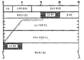
- FIG. 1 is a view for explaining the concept of a flexible address operation according to an embodiment of the present invention.
- the network system shown is largely divided into a local network and a backbone network.
- the local network includes a plurality of flexible routers (FR) that perform routing based on flexible local addresses, and the local network is connected to the backbone network via a local global router (LGR).
- the local global router LGR is connected between the local network and the backbone network to perform translation of the flexible local address FLA and the flexible global address FGA.
- the backbone network includes a plurality of backbone routers BR that perform routing based on the flexible global address.
- One or more FLA nodes may be connected to a lower end of the flexible router FR.
- the FLA node can generate a flexible local address by referring to information provided by a local global router.
- Such a FLA node may have one or several node identifiers. Meanwhile, communication between FLA nodes may be performed based on the node identifier.
- the FLA node may perform the same function as the FLA router (FR) in a multi-hop environment such as MANET.
- FIG. 2 is a diagram for describing a location information structure generated according to an embodiment of the present invention.
- location information may be represented using absolute location information such as latitude, longitude, height, or relative location information using names such as “empire state building” or “golden gate”. Can be.
- the location information may be represented as global location information or local location information.
- the global location information may be an absolute location or a relative location using a region / country code, whereas the local location information may be represented by a relative distance from a reference point or an area range. Relative information to be described.
- the location information may be represented using a reference point or not, while the absolute position information may be described without the reference point, while the relative position information may be represented by a direction and a distance from a specific reference point.
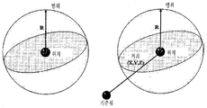
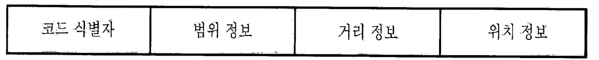
- 3A and 3B are views for explaining a locator structure according to an embodiment of the present invention.
- the locator may include a code identifier field, a range information field, a distance information field, and a location information field. That is, the locator can describe specific location information, and can describe an area centered on the specific location information using area information. The locator can also describe relative positions spaced apart by distance information from a particular position.
- the code identifier field includes information for identifying the format and type of the locator.
- the locator is classified into ASCII format, binary format, or user defined format.
- the code identifier distinguishes the type of location information defined by the location information field. For example, it distinguishes whether the position information indicated by the position information field is absolute position information or relative position information.
- the range information and the distance information may vary according to the information of the code identifier field.
- the range information field indicates an area centered on the point indicated by the location information field.
- the range information may be variously used for detecting a range of a node, a cover area of the node, or an error area.
- the range information field includes a range, a unit, a scale, and the like. The unit may indicate kilometers (km), meters (m), or the like. The range information field may not be used depending on the selection.
- the distance information field is used to indicate a relative position from a point included in the location information field. That is, the final position may be a position spaced apart from the reference point included in the position information field by distance information.
- the distance information field may not be used according to the user's selection.
- the location information field may include a reference point of absolute location information or relative location information.
- the absolute position information may be determined by latitude, longitude, and altitude, and the relative position information may be represented in the form of relative position information from a reference point.
- the code identifier field may be used to distinguish the type of location information described in the location information field.
- the locator may use a hierarchical structure.
- the node identifier is a globally unique identifier of the FLA node, the node identifier of all nodes can be confirmed in advance.
- the flexible local address is an address of a FLA node used in a local network, and the flexible local address has an interface for each interface of the FLA node.
- the FLA node may generate the FLA by referring to information provided by the LGR (FLA-FGA Router).
- FLA can be used as information for routing in the local network.
- the FLA can be used as information for creating a virtual circuit.
- Network prefixes can have hierarchical locators.
- the FLA is an addressing type that indicates what addressing to use, a mobile / fixed node flag that indicates whether the interface to which the node is connected is mobile or fixed, whether the address is available only within the local network, A backbone / local flag indicating whether it is also available in the backbone network, bandwidth information indicating bandwidth information of the interface to which the node is connected, CPU information indicating CPU performance information of the node, Virtual circuit flag indicating whether the virtual circuit is supported, information about the range of using the virtual circuit (Virtual Circuit region), virtual circuit label indicating the label used by the virtual circuit, and service type ( Service type), and other characteristic information of the node.
- the field may include fields such as node information, an ID indicating an ID distinguishable from other nodes, and a locator (LOC) indicating hierarchical location information of the node.
- the flexible global address is an address of the LGR as used in the backbone network.
- Flexible global addresses can be manually or automatically configured to be globally unique.
- Flexible global addresses can be used as routing information in the network.
- Flexible global addresses can be used as information for creating virtual circuits.
- Network prefixes can have hierarchical locators.
- the FGA has an addressing type that indicates which addressing to use, a mobile / fixed node flag that indicates whether the interface to which the node is connected is mobile or fixed, whether the address is available only within the local network, A backbone / local flag indicating whether it is also available in the backbone network, bandwidth information indicating bandwidth information of the interface to which the node is connected, CPU information indicating CPU performance information of the node, Virtual circuit flag indicating whether the virtual circuit is supported, information about the range of using the virtual circuit (Virtual Circuit region), virtual circuit label indicating the label used by the virtual circuit, and service type ( Service type), and other characteristic information of the node.
- the field may include fields such as node information, an ID indicating an ID distinguishable from other nodes, and a locator (LOC) indicating hierarchical location information of the node.
- LOC locator
- a flexible router (FAS Router, FR) is a router that determines a path using a FLA in a local network and may have a hierarchical structure.
- a backbone router (BR) may determine a path using an FGA in a backbone network, and the backbone router may have a hierarchical structure.
- the FLA node may have one or several NIDs, and communication between the FLA nodes may be made through the NID.
- the FLA node can perform a FR-like function in a multi-hop environment such as MANET.
- LGR is a router that performs translation between FLA and FGA between local network and backbone network.
- the LGR may have one or more interfaces in the local network, one or more interfaces in the backbone network, and may have a hierarchical structure.
- the LGR converts FLA to FGA for outbound traffic, uses the FGA's source address as its FGA, and uses the lookup result with the destination NID as the destination address of the FGA.
- LGR converts FGA to FLA for inbound traffic, uses the FLA's source address for its FLA, and uses the lookup result with the destination NID of the FLA.
- LGR converts the LLMP of the packet received from the FLA node into GLMP and sends it. For example, convert an LLMP type such as LRR to a packet of GLMP type such as GRR. LGR converts GLMP from NFS to LLMP and sends it. For example, convert a GLMP type such as GRA into a packet of LLMP type such as LRA.
- the LGR maintains list information on NID-FLA mapping table of local network nodes, NID-FGA mapping table of backbone network nodes, and corresponding nodes of inner nodes for communication between FLA nodes.
- NFS NID-FGA System
- NFS is a database system that contains NID and FGA information. NFS processes and responds to GLMP sent by LGR. NFS can have a hierarchical structure. NFS maintains information such as NID and FGA.
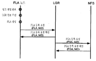
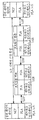
- FIG. 4 is a view for explaining a data packet forwarding method according to an embodiment of the present invention.
- the data packet sent from the sending FLA node to the receiving FLA node is delivered through the following process.
- the sending FLA node forwards the data packet to the sending LGR (LGR_S).
- LGR_S the sending LGR
- LDP Local Delivery Protocol
- Receiving this packet the sending LGR (LGR_S) converts the LDP into a backbone delivery protocol (BDP).
- BDP backbone delivery protocol
- the transmitting LGR (LGR_S) delivers the data packet to the receiving LGR (LGR_R) using the BDP.
- BDP backbone delivery protocol
- Receiving LGR receiving this packet converts BDP to LDP.
- the receiving LGR then forwards the data packet to the receiving FLA node using LDP.
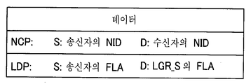
- 5A to 5C are diagrams for describing a data packet forwarding method according to an embodiment of the present invention.
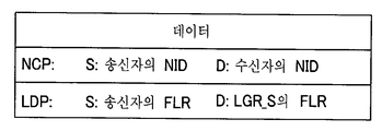
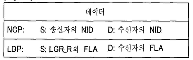
- the sending FLA node generates a packet as shown in FIG. 5A to send a data packet to the receiving FLA node.
- the source of an NID uses its own NID
- the destination of the NID uses the recipient's NID.
- the source FLA of the LDP uses its own FLA
- the destination FLA of the LDP uses the transmitting LGR (LGR_S).
- the structure of the data packet sent by the transmitting FLA node to the transmitting LGR (LGR_S) is as shown in Figure 5a. That is, in the local network shown in FIG. 4, the transmission FLA node and the transmission LGR (LGR_S) are routed using the FLA. More details will be described later.
- LGR_S transmitting LGR
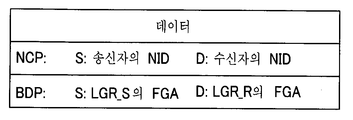
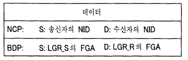
- LGR_R receiving LGR
- the NID uses the NID of the sending FLA of the NID without change, and the destination of the NID uses the NID of the receiving FLA.
- the FLA of the LDP will be converted to the FGA of the BDP.
- the source of the BDP uses the FGA of the transmitting LGR (LGR_S) and the destination of the BDP uses the FGA of the receiving LGR (LGR_R).
- LGR_S transmitting LGR
- LGR_R the FGA of the receiving LGR
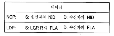
- FIG. 5C illustrates a data packet transmission process between a receiving LGR (LGR_R) and a receiving FLA node. That is, the receiving LGR (LGR_R) receiving the data packet shown in FIG. 5B from the backbone network converts the data packet as follows and transmits the data packet to the local network.
- LGR_R receiving LGR
- the NID uses the NID of the sending FLA of the NID without change, and the destination of the NID uses the NID of the receiving FLA.
- the FGA of the BDP will be converted to the FLA of the LDP.
- the source of the LDP uses the FLA of the receiving LGR (LGR_R), and the destination FLA is used for the destination of the LDP.
- the data packet sent by the receiving LGR (LGR_R) to the receiving FLA node is as shown in Figure 5c.
- the receiving LGR (LGR_R) and the receiving FLA node are routed using the FLA. More details will be described later.
- the FLA used on the local network and the FGA used on the backbone network include the locator (LOC). Therefore, LGR maintains NID-FLA mapping table for LOC management of FLA node of local network and caches NID-FGA mapping table for LOC management for corresponding FLA node. NFS maintains NID-FGA mapping table information for all FLA nodes.
- LGR maintains NID-FLA mapping table for LOC management of FLA node of local network and caches NID-FGA mapping table for LOC management for corresponding FLA node.
- NFS maintains NID-FGA mapping table information for all FLA nodes.
- LLMP is used to manage LOC between FLA node and LGR.
- the FLA node performs FLA registration using LLMP.
- LGR uses GLMP to perform FGA registration. At this time, LGR performs the conversion of LLMP and GLMP between the FLA node and NFS.
- LGR uses GLMP for mobility of FLA nodes.
- 6A and 6B are diagrams for describing a configuration of a mapping table for LOC management.
- the NID-FLA mapping table shown in FIG. 6A, is used to manage FLA information of FLA nodes in the local network.
- the NID-FLA mapping table contains information on the mapping relationship between NIDs and FLAs.
- LGR maintains a NID-FLA mapping table for FLA nodes in the local network.
- the FLA node may have a NID-FLA mapping table for FLA nodes in the same local network.
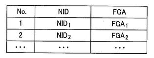
- the NID-FGA mapping table shown in FIG. 6B, is used to manage FGA information of FLA nodes in the backbone network.
- the NID-FGA mapping table contains information on the mapping relationship between NIDs and FGAs.
- the LGR caches the NID-FGA mapping table for the correspondent node with which the FLA node of the local network communicates.
- NFS maintains the NID-FGA mapping table in accordance with LGR's GLMP.
- NFS has a NID-FGA mapping table for every FLA node.
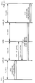
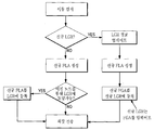
- FIG. 7 is a diagram illustrating a LOC registration process of a FLA node in a network system according to an embodiment of the present invention.
- the FLA node performs the interface link setup, and when this process is completed, the FLA node receives the LGR information.
- the FLA node generates a FLA based on its LOC information and LGR information.
- the FLA node requests the LGR to register the FLA, which includes the FLA and the NID.
- the LGR sends a confirmation message to the FLA node that it has completed registration of the FLA in response to the request.
- the LGR requests the NFS to register the FGA, which includes the NID information of the FLA node and the FGA of the LGR.
- NFS sends a confirmation message to the LGR that it has completed registration of the FGA.
- FIGS. 8A to 8D are diagrams for describing a process of querying locator information in a network system according to an embodiment of the present invention.
- the transmitting FLA node and the receiving FLA node register the FLA with each LGR (LGR_S, LGR_R).
- the transmitting LGR (LGR_S) and the receiving LGR (LGR_R) perform FGA registration of each node.
- the sending FLA node sends the data packet shown in FIG. 8B to the receiving FLA node.
- the transmitting LGR LGR_S
- the transmitting LGR searches the NID-FGA mapping table cached with the receiver NID. If there is no corresponding FGA in the search result table, the FGA query including the NID of the receiving FLA node is transmitted to NFS. In contrast, NFS retrieves the NID of the receiving FLA node, retrieves the corresponding FGA, and returns to the sending LGR (LGR_S).
- the transmitting LGR updates the FGA received from the NFS in the NID-FGA mapping table by matching the NID of the receiving FLA node.
- the transmitting LGR converts the FLA into an FGA and transmits a data packet, which is sent to the receiving LGR (LGR_R). At this time, the structure of the transmitted data packet is as shown in Figure 8c.
- the receiving LGR (LGR_R) receiving the data packet shown in FIG. 8C maps the sender's NID and the sender's FGA and updates the NID-FGA mapping table. If it is not in the search result mapping table, the receiving LGR (LGR_R) sends the FGA query including the receiver's NID to NFS. The receiving LGR (LGR_R) converts the FGA into an FLA and transmits the data packet shown in FIG. 8D.
- the network system of the present invention proposes a routing method for a mobile FLA node.
- FIG. 9 is a view for explaining a process of moving a FLA node according to an embodiment of the present invention.
- two movement processes may proceed according to whether the node detected the movement has moved within the same LGR.
- the FLA nodes move within the same local global router.
- a new locator is created, which changes the flexible local address.
- the flexible global address does not change.
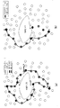
- FIG. 10 is a diagram illustrating a routing method according to a location change of a FLA node in a network system according to an embodiment of the present invention.
- the network is a multi-hop network such as MANET.
- the FLA node H is performing communication with the LGR through another FLA node A at the first time point t1.
- the FLA node H moves, and accordingly, the FLA node H generates a FGA with a new locator.
- the FLA node (H) since the FLA node (H) is located within a predetermined distance in relation to the FLA node (A), communication can be performed through the FLA node (A), it may not notify the LGR of the new FLA.
- the FLA node H moves to a new position at the third time point t3, the FLA node H similarly generates a FLA with a new locator.
- the FLA node H since the FLA node H is located outside the predetermined distance in relation to the FLA node A, the FLA node H can communicate with the LGR through the new FLA node B. To do this, a new FLA is sent to the LGR.
- the FLA node moves to an area covered by a different LGR.
- the FLA not only the FLA but also the FGA is changed.
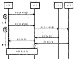
- FIG. 11 is a diagram illustrating a method of changing a router according to a change of a location of a node in a network system according to an embodiment of the present invention.
- the FLA node While the FLA node communicates with the other FLA node through the LGR (LGR_Old) before the change, the FLA node moves to the network in charge of the new LGR (LGR_New) due to the location change. Accordingly, the FLA node receives the information of the new LGR (LGR_New) after performing the interface link setup. In addition, the FLA node generates a new FLA with the locator information generated for the new location and the information of the new LGR (LGR_New).
- the FLA node goes through a procedure of registering a new FLA with a new LGR (LGR_New), where it can transmit FLA and NID for its locator registration. Thereafter, the new LGR (LGR_New) registers a new FLA of the FLA node.
- LGR_New new LGR
- the new LGR (LGR_New) transmits a change request of the FGA including the node identifier and the FGA of the FLA node whose location has been changed to NFS.
- NFS searches the NID-FGA mapping table based on the NID of the FLA node whose location has been changed, and checks the pre-change LGR (LGR_Old) in charge of the FLA node before the location is changed. Thereafter, NFS sends an FGA binding request including the NID and FGA information of the FLA node whose location has been changed to LGR (LGR_Old) before the change.
- the LGR updates its NID-FGA mapping table and transmits an FGA binding acknowledgment message.
- NFS sends an FGA confirmation message to the new LGR (LGR_New).
- the previous LGR retrieves a list of counterpart FLA nodes communicating with the relocated FLA node, and then changes its location to the router (LGR_R) in charge of the counterpart FLA node according to the search result.
- the flexible global address update request including the NID and the flexible global address of the FLA node is transmitted.
- the router LGR_R updates its NID-FGA mapping table and transmits a confirmation message to the previous router LGR_Old to confirm that it is completed.
- the old router LGR_Old transmits a data packet to the new router LGR_New through tunneling before updating the flexible global address.
- the FLA node and the flexible router (FR) in charge of the local network can create and use a virtual circuit using the FLA, and the backbone router (BR) in charge of the backbone network creates a virtual circuit using the FGA. Can be used. Through this virtual circuit, QoS guarantee, low delay, and traffic management characteristics can be secured.
- FGA routing determines the path between LGRs.
- the following routing scheme may be used according to the addressing type of the FGA.
- the longest prefix matching (LPM) method of the FGA according to the IP routing scheme such as the existing Internet may be used.
- LPM longest prefix matching
- a routing method using locator information of the FGA can be used.
- a method of constructing a virtual circuit using a virtual circuit label can be used.
- FGA routing determines the path between the LGRs, between the backbone router BR and the LGR or between the backbone routers.
- the LGR may use the FGA information and the path information when generating the virtual circuit, and each information may include the following information.
- the FGA information may include the mobile / fixed node flag of the FGA, bandwidth information of the FGA, CPU information, and node information.
- the path information may include the hop count of the path, the bandwidth of the path, the link state, the delay state of the path, and the load state. Information may be included.
- a virtual circuit may be used by more than one FGA, or may use one FGA through several virtual circuits. In this case, which virtual circuit is used may be determined by service, traffic, delay, and the like.
- the routing of the FLA determines the path between the LGR and the FLA node.
- the following routing scheme may be used according to the addressing type of the FLA.
- the longest prefix matching (LPM) method of the FLA according to the IP routing scheme such as the existing Internet may be used.
- LPM longest prefix matching
- a routing method using locator information of the FLA can be used.
- a method of constructing a virtual circuit using a virtual circuit label can be used.
- FLA routing determines the path between the LGR and the flexible router (FR), between the LGR and the FLA node, between the FLA node routers (FR), between the flexible router (FR) and the FLA node, between the FLA nodes.
- the LGR, the flexible router, and the FLA node may use the FLA information, the path information, and the node state information when generating the virtual circuit, and each information may include the following information.
- the FLA information may include the mobile / fixed node flag of the FLA, bandwidth information of the FLA, CPU information, and node information.
- the path information may include the hop count of the path, the bandwidth of the path, the link state, the delay state of the path, and the load state.
- the node state information may include strength of an interface signal, a distance of a neighbor node, and battery state information.
- a virtual circuit may be used by more than one FLA or may use a single FLA through several virtual circuits. In this case, which virtual circuit is used may be determined by service, traffic, delay, and the like.
- LMPs Location management protocols
- GLMP Global Location Management Protocol
- LLMP Local Location Management Protocol
- GLMP is used between LGRs or between LGR and NFS in a backbone network.
- GLMP is used for FGA node maintenance and for NID-to-FGA queries using NID.
- a FGA Register REQ message of a flexible global address is sent by the LGR to NFS when registering a new FLA node's NID.
- the flexible global address registration request acknowledgment message (FGA Register ACK) is sent by NFS to the LGR in response to the GRR.
- a flexible global address translation request message (FGA Transfer REQ) is sent when the new LGR notifies NFS of the FLA node's movement.
- the flexible global address translation request confirmation message (FGA Transfer ACK) is transmitted by NFS to the new LGR in response to the GTR.
- the flexible global address binding request message (FGA Binding REQ) is sent when NFS informs the LGR of the FLA node's movement before the change.
- Flexible Global Address Binding Request Acknowledgment Message GGA (FGA Binding ACK) is sent by LGR to NFS in response to GBR before modification.
- the flexible global address update request message (FGA Update REQ) is transmitted when the LGR informs the LGR of the CN to move the FLA node before the change.
- the flexible global address update request confirmation message (FGA Update ACK) is transmitted to the LGR before the change by the LGR of the CN in response to the flexible global address update request message.
- a flexible global address query message (FGA Query) is sent when LGR queries NFS for FGA with NID.
- Flexible Global Address Response Message GLA (FGA Reply) is sent by NFS to the LGR in response to a flexible global address query message.
- LLMP is used between the FLA node and LGR in the local network. LLMP is used to maintain the FLA of a FLA node.
- a flexible local address registration request message (FLA Register REQ) may be sent when the FLA node registers the FLA node FLA with the LGR, and a flexible local address registration request confirmation message (FLA Register ACK) may be sent to the LG FLA node. Send in response to a local address registration request message.
- FLA Register REQ a flexible local address registration request message
- FLA Register ACK a flexible local address registration request confirmation message
- FIG. 12 is a view for explaining the configuration of the NCP according to an embodiment of the present invention.
- NCP NID Communication Protocol
- FLA end nodes uses NID.
- Delivery protocols include BDP and LDP.
- FIGS. 13A and 13B are diagrams for describing a configuration of a data transmission protocol according to an embodiment of the present invention.
- BDP Backbone Delivery Protocol
- the BDP header contains the sender (source FGA) and receiver (destination FGA). Packets between LGRs use the FGA, and the sender uses the FGA of the sender network LGR and the receiver uses the FGA of the receiver network LGR.
- the Local Delivery Protocol shown in FIG. 13B, is used to carry data packets between the FLA node and the LGR in the local network.
- the LDP header contains the sender (source FLA) and receiver (destination FLA). Packets between the FLA node and the LGR use the FLA.
- FIG. 14 is a diagram illustrating a geographical routing method on a network system according to an embodiment of the present invention.
- Geographic routing algorithms include Location Based Routing (LBR) method, Topology Based Routing (TBR) method in wireless multi-hop network, and Gateway Traversal Routing (GTR) method for Internet connectivity. Is done.
- LBR Location Based Routing
- TBR Topology Based Routing
- GTR Gateway Traversal Routing
- each node basically uses a greedy forwarding method in order to send a packet to a destination, which is a neighbor node whose node is closer to the destination node than the node receiving the packet. To forward the packet.
- 15 is a view for explaining a problem of the greedy forwarding method.
- the greedy forwarding method does not work when none of the neighbor nodes is closer to the destination node than the current node.
- a node is called dead-end, and the isolation of a packet from the dead-end node is called a void (hole) or local-minimum.
- 16 is a diagram illustrating an improved greedy forwarding method in a network system according to an embodiment of the present invention.
- Location-based routing's path recovery mode is initiated on dead-end nodes that encounter local minimums that cannot be greedy forwarded.
- the dead end node enters a path recovery mode such as a perimeter mode of the Greedy Perimeter Stateless Routing (GPSR) (indicated by a dotted line in FIG. 16A).
- GPSR Greedy Perimeter Stateless Routing
- the boundary mode is to deliver packets continuously according to the right hand rule.
- the destination node of the boundary mode is reached, that is, the node closer to the destination than the dead end node, the packet is delivered again according to the greedy mode.
- this intermediate node when the intermediate node receiving the packet is closer to the destination than the dead-end node, this intermediate node is called a redirect node, and the intermediate node refers to that information in the redirect list field of the packet's routing header. After recording, restart greedy mode.
- the destination node If the packet arriving at the destination includes the redirect node list information, the destination node transmits a control message called a redirect list information (RLI) message including the redirect list information to the source node. If this control message to the source node is isolated to the dead end, the intermediate node is called a reverse redirect node, and the intermediate node records the information in the redirect list field of the RLI message.
- RLI redirect list information
- the source node may select either the path based on the forward path hop count from the source node to the destination node and the path based on the reverse path hop count from the destination node to the source node. . Accordingly, as shown in FIG. 16B, the source node may use a redirect routing header when forwarding a packet to be forwarded to the same destination node, thereby avoiding a dead end node and forwarding the packet through the redirect node. . This allows packets to be delivered while eliminating the local minimum problem.
- the source node may not know the exact location information of the destination node. Therefore, since a routing loop may occur due to the inaccurate location information of the destination node, it is not sufficient to deliver the packet only by the location-based routing method.
- NI Neighbor information
- each node may maintain local topology information within two hops.
- the NI message contains the information of the sender node and the ID information of the neighbor node in its one hop.
- Such a topology-based routing method can solve a routing loop problem caused by inaccurate location information of a destination node in a wireless multi-hop network.
- nodes one hop away from the gateway for Internet access maintains gateway information by receiving a router advertisement message from the gateway.
- Nodes that are two hops away from the gateway receive an NI message that includes a gateway list field from nodes one hop away from the gateway.
- Nodes in a multi-hop network can gradually recognize gateway information through periodic NI messages.
- Each node can set the global IP address using the gateway prefix information.
- Each node managing gateway information through the gateway list table compares the prefix information of the gateway with the prefix information of the destination node, and determines whether the destination node is in the multi-hop network. If the destination node is an Internet node, the source node transmits a packet including a GTR header to be delivered through its default gateway, and each intermediate node transmits the packet to the gateway.
- the geographical address system basically has a length of 128 bits and includes an address identifier field, a location information field, a range field, and an ID field.
- the address identifier field corresponds to a field specifying that the geographical address is a geographic base address. That is, an address identification code for specifying that the address identifier field is an address separate from an existing IPv4 or IPv6 address is stored.
- the radical transition from the current network to the new geographical addressing system is virtually difficult.
- the transition to the IPv6 is gradually progressing through a network transition step in which an IPv4 / IPv6 network coexists using various transition mechanisms.
- the geographical address system according to the present invention is based on 128 bits equal to the IPv6 address length so that it can be applied to the next generation IP version of IPv6.
- the address identifier field identifies whether the upper 8 bits are a geographical address in consideration of an IPv6 address and translation. If the geo-based address is not used universally but is used only in a limited network, it needs to be changed to an IPv6 address (or IPv4 address) in order to receive service from the general-purpose network.
- the address identifier field may be used to determine whether address translation is required, such as IPv4 / IPv6 translation mechanism (NAT-PT).
- NAT-PT IPv4 / IPv6 translation mechanism
- the location information field corresponds to a field including location information of the terminal.
- the location information field includes latitude, longitude, and altitude which are location information obtained by using a similar mechanism such as GPS of the terminal.
- Latitude and longitude information is described in degrees, minutes and seconds, and seconds include up to two decimal places.
- the location information may be represented by 8 bytes.
- Latitude is divided into north latitude or south latitude and is expressed in degrees, parts, and seconds.
- Degrees are values between 0 and 90
- minutes are between 0 and 60.
- Seconds are represented by two digits after the decimal point and two digits after the decimal point and have a value between 0 and 60.
- Longitude is divided into longitude or longitude and is expressed in degrees, minutes, and seconds. Degrees range from 0-180 and minutes range from 0-60. In addition, the second is represented by two digits after the decimal point and two digits after the decimal point and has a value between 0 and 60. Elevation is expressed in height and unit, height is in the range 0-999, and unit is m and km. Height and units can be modified to take account of the practical use in the environment.
- the location information obtained by the terminal may be obtained by using a location measurement system such as a GPS provided in the terminal, but if the terminal does not have a location measurement system or the system cannot be operated, it is necessary to obtain the location information.
- a location measurement system such as a GPS provided in the terminal
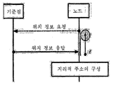
- FIG. 17 is a diagram illustrating a procedure for setting an address by obtaining location information from a reference point when there is no location measuring system necessary for address setting or system operation is impossible and thus location information is not obtained.
- a terminal having difficulty in obtaining location information transmits a location information request message to a reference point (eg, an access point), and includes location information response including location information of the reference point.
- a reference point eg, an access point
- location information response including location information of the reference point.
- Reply Acquire location information through message reception, and set geographical address through location information and own MAC address.
- the location information should be considered even when the terminal is located in a multihop network environment.
- the location information is obtained through a location information response message received from neighboring neighbor nodes after the terminal transmits a location information request message in a range of 1 hop, and the location information response message is received within a predetermined time. If not, it is obtained by extending the transmission range of the location information request message to two or more hops.
- FIGS. 20 and 21 illustrate a process in which the terminal sets a geographical address in the 1-hop range and the 2-hop range, respectively. Shows.
- a location information request message is transmitted in a hop range and received from neighboring neighbor nodes.
- a geographical address is set through a geolocation response message.
- the transmission range of the location information request message is extended to two hops for location information acquisition. This takes into account the case that the 1-hop range neighbor nodes of the terminal also do not have location information.
- the location information is obtained from a terminal having location information within two hop ranges extended to two hop ranges. Set the geographical address by receiving.
- the range field corresponds to a field including information on whether the destination is a single destination or a local destination and area range information when the destination is a local destination. If there is no value in the range field, it may be determined as a single destination, and if there is a specific value, it may be determined as a local destination.
- the range field represents the range of the local destination based on the location information of the location information field, and the local destination represents the local destination range in the form of a three-dimensional circle, cube, or polygon. do.
- the range field is basically applied to the geographical address of the communication partner, and there is no information expressed when the communication partner is a single terminal (single destination) (there is no specific value). However, when the communication partner is not one terminal, that is, when the packet is transmitted to the terminals in a specific region (geocast region), the range field indicates region (range) information necessary for geocasting that transmits the packet to a specific region. Include.
- the range field when the value of the upper two bits of the range field is 0, it means that the geographical address to be set does not include a specific region (range) (meaning a single destination). At this time, since the range field represents a single destination, the ID field does not need to express a detailed area range for the local destination, and the MAC address of the terminal is stored.
- the geographical address to be set represents a specific region (range) in the form of a circle. That is, a specific region is described by expressing the radius around the point expressed in the location information field. The radius length is described as a value between 0 and 999 (10 bits), and the unit considers m and km.
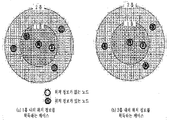
- FIG. 2 shows an example of a case where a specific region is represented by a circle with a geographical address.
- the geographical address to be set represents a specific region (range) by a cuboid.
- the range that can be expressed varies according to what criteria the points included in the location information field are expressed.
- a specific region expression may vary depending on how the specific region (part represented by a thick line) is expressed at a reference point (part represented by a sphere).
- Information for a specific area representation is described in the ID field representing detailed information of a local destination. If the ID field has a spatial limitation in the information representation, an IPv6 extension header may be used.
- the local destination range may be expressed in detail in the ID field, and when not represented by the ID field, it may be expressed using an IPv6 extension header. This will be described later.
- the ID field corresponds to a field including detailed information of a region range indicated by the MAC address or the range field of the terminal. Specifically, the ID field represents the MAC address of the terminal when the destination is a single destination, and detailed information of the local range displayed in the range field when the destination is a local destination.
- the ID field is an address set to a single terminal (single destination)
- a MAC (Media Access Control) address assigned to the network interface card of the terminal is included.
- the ID field including the MAC address is used to distinguish each terminal as a unique address from an error of information obtained from the positioning system (GPS or similar mechanism) of the terminal.
- the ID field when expressing a specific region (regional destination) as an address, includes detailed information of the specific region (range) that cannot be represented by the space constraint of the range field.
- the specific region may be represented by a circle, a cuboid, a polygon, and the like, and when there are restrictions on the representation of the specific region with 48 bits of the ID field, the use of an extension header of IPv6 may be considered as shown in FIG. 22.
- IPv6 extension header describes the options of the existing IPv6 header and newly added functions in IPv6. Extension headers add functionality required for communication after the IPv6 default header.
- the packet is composed of the IPv6 basic header, and the extension header is added after the basic header to meet the needs of the communication to increase the routing efficiency.
- IPv6 extension headers defined to date include the hop-by-hop option header, routing header, split header, authentication header, encapsulating security payload (ESP) header, and destination option header.
- ESP encapsulating security payload
- extension header Detailed description of the extension header is as follows.
- Table 1 below shows the initial extension header. Every extension header (except 59) has its own next header field. This structure allows IP to continue arranging multiple extension headers in sequence. The last extension header uses its next header field to specify a high-level protocol.
- Figure 23 shows a datagram with some extension headers. As shown in FIG. 23, it is possible to specify how each header specifies a next header up to an authentication header.
- the next header field in the authentication header specifies the high-level protocol (TCP in this case).
- IPv6 extension headers are not sized, it is possible to further develop various kinds of IPv6 extension headers. Therefore, in the basic geographical address system (128 bits), detailed information may be described using an IPv6 extension header when there is a spatial limitation in the range information representation.
- the terminal receiving the packet including the geographic address according to the above-described geographic address setting method compares the location information, the range, and the ID field of the geographic address of the packet, and determines whether to receive the packet according to a match.
- the terminal receiving the packet including the geographical address checks the range field of the geographical address included in the received packet, when it is represented as a single destination, its own MAC address and information included in the ID field match. Only one packet is received.
- the terminal receiving the packet including the geographic address checks the range field of the geographic address included in the received packet, if the terminal is represented as a local destination, the terminal receives itself in the destination regional range represented by the range field and the ID field. Receive the packet only if it is included.
- packet reception is determined by comparing whether the location of the receiving terminal is included in the specific region expressed in the location information field and the range field.
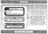
- the terminal for automatically setting the geographical address described above is basically a module for acquiring location information and MAC address to set an address, a special case for transmitting a packet to a specific region, a module for setting a relative address by specifying a specific region, It should include a packet reception determination module.
- the terminal is provided with a location information receiving unit, obtains the location information of the terminal from the GPS or similar mechanism mounted on the terminal, and if it is difficult to receive the location information by itself to the surrounding location information request and response message to the reference point Obtain location information.
- the location information of the terminal is obtained through parsing a data structure system including an address identifier field, a location information field, a range field, and an ID field.
- Location information of the terminal may include latitude, longitude, altitude, and the like.
- the terminal according to the present invention should be provided with a MAC address obtaining unit, which obtains MAC (Media Access Control) address information assigned to the network interface card of the terminal.
- MAC Media Access Control
- the terminal according to the present invention should be provided with a location range designator, the location range designator, if the destination of the packet transmitted in response to the counterpart terminal in the terminal transmitting the packet to include a specific area, the location range The designation unit calculates a specific area range based on the information obtained by the location information receiving unit and adds it to the range information field of the data structure system according to the present invention.
- the address of the terminal is expressed as a single terminal that does not include a specific region, no part is processed by the location range designator.
- the terminal according to the present invention should be provided with a geographical address determination unit, the geographical address determination unit according to the geographical address system of the present invention based on the information obtained from the location information receiver, MAC address acquisition unit, location range designation unit Set the address.
- the terminal according to the present invention should be provided with a packet reception determining unit, which determines whether to receive a packet by looking at the destination address of the received packet.
- the packet receiving terminal determines whether the packet is received according to whether the packet reception terminal is included in a specific range which is a destination represented by the location information field, the range field, and the ID field of the destination address. .
- the destination address represents one terminal rather than a specific region
- the terminal according to the present invention includes a relative location range designation unit and a relative address determination unit for the case where the destination of the communication is not a single terminal but a specific region.
- the packet reception determining unit according to the present invention determines whether to proceed with the IP address information processing process or the geographic address information processing process using the information in the address identifier field. The received packet is transmitted to each processing process according to the determined result.
- the location range designation unit When the relative location range designation unit intends to designate the terminals included in a specific area as a destination of a packet, the location range designation unit designates a range of a destination, and sets a destination address in the relative address determination unit based on this information. do.
- IPv6 also has the advantage of address autoconfiguration, but it is done via router advertisement message with network prefix from router which is external terminal.
- the present invention has the advantage that the network construction is simpler because the address can be automatically set without the help of a router.
- the geographic address is applied, it is expected to be used in a limited network preferentially, and thus, the following functions are provided in a gateway providing connectivity between two networks in order to support interconnection between a corresponding address system-based network and an external network.
- a gateway connecting the network using the geographical address and the network using the existing IP address performs address translation to perform the geographical address. Send a packet to the network using the existing IP address.
- the gateway converts the geographical address into the existing IP address, stores address information before and after address translation of the terminal that has transmitted the packet including the geographical address in a table, and uses the information stored in the table. To determine the transmission destination of the packet received from the network using the existing IP address.
- the gateway connected to the network using the existing IP address and the network using the geographic address includes an apparatus for address translation when forwarding packets to an external network for smooth communication.
- the gateway that forwards the packet transmitted by the terminal inside the network using the geographical address to the external network converts the geographical address of the transmitting terminal into a global IP address suitable for the external network, and converts the address information before and after the translation of the transmitting terminal into a table. It stores the destination address of the packet received from the counterpart terminal based on this table information and delivers it to the internal destination terminal.
- the global IP address translation of the internal terminal in the gateway including the address translator may be converted into an IPv4 or IPv6 address according to the IP version of the external network connected to the gateway. Perform the conversion.
- One embodiment of the present invention can be applied to IPv6 structure, switch and routing device, media gateway, IMS, soft switch, application server, firewall, and various ubiquitous computing devices related to future network technology.
- an embodiment of the present invention is applied to various network equipment constituting the network infrastructure, as well as all user terminals using various wired and wireless networks, such as PC, home appliances, smart phones, office equipment, M2M, smart grid, sensor network. As such, the scope of application can be continuously extended.
- Computer readable media can be any available media that can be accessed by a computer and includes both volatile and nonvolatile media, removable and non-removable media.
- Computer readable media may include both computer storage media and communication media.
- Computer storage media includes both volatile and nonvolatile, removable and non-removable media implemented in any method or technology for storage of information such as computer readable instructions, data structures, program modules or other data.
- Communication media typically includes computer readable instructions, data structures, program modules, or other data in a modulated data signal such as a carrier wave, or other transmission mechanism, and includes any information delivery media.
Landscapes
- Engineering & Computer Science (AREA)
- Computer Networks & Wireless Communication (AREA)
- Signal Processing (AREA)
- Databases & Information Systems (AREA)
- Data Exchanges In Wide-Area Networks (AREA)
- Mobile Radio Communication Systems (AREA)
- Small-Scale Networks (AREA)
Abstract
Description
| IP Extension Header | |
| 0 | Hop-by-Hop Options Header |
| 43 | Routing Header |
| 44 | Fragment Header |
| 51 | Authentication Header |
| 59 | No Next Header |
| 60 | Destination Options Header |
Claims (10)
- 노드에 대한 네트워크 어드레스 생성장치에 있어서,상기 노드가 위치한 지점의 위치 정보를 정의하는 로케이터를 포함하는 플렉서블 어드레스 및 상기 노드의 식별 정보를 포함하는 노드 식별자를 포함하는 네트워크 어드레스를 생성하는 네트워크 어드레스 생성장치.
- 제 1 항에 있어서,상기 로케이터는 상기 노드가 위치한 지점의 위도, 경도, 고도 및 절대적 위치로부터의 영역범위 정보 중 적어도 하나 이상을 포함하는 절대 로케이터를 포함하는 네트워크 어드레스 생성장치.
- 제 1 항에 있어서,상기 로케이터는 기준점으로부터의 상기 노드의 거리 및 상기 기준점으로부터의 상기 노드의 영역범위 정보 중 적어도 하나 이상을 포함하는 상대 로케이터를 포함하는 네트워크 어드레스 생성장치.
- 제 1 항에 있어서,상기 플렉서블 어드레스는 로컬 네트워크에서 사용되는 플렉서블 로컬 어드레스와 백본 네트워크에서 사용되는 플렉서블 글로벌 어드레스를 포함하는 네트워크 어드레스 생성장치.
- 제 1 항에 있어서,상기 노드의 네트워크 어드레스는어드레싱 타입을 나타내는 어드레싱 타입 필드,상기 노드가 연결되어 있는 인터페이스가 모바일인지 고정형인지를 나타내는 모바일/고정형 노드 플래그,상기 네트워크 어드레스가 로컬 네트워크 내에서만 사용 가능한지, 백본 네트워크에서도 사용 가능한지를 나타내는 백본/로컬 플래그,상기 노드가 연결되어 있는 인터페이스의 대역폭 정보를 나타내는 대역폭 정보,상기 노드의 CPU 성능 정보를 나타내는 CPU 정보,가상 회로를 지원하는지를 나타내는 가상 회로 플래그,가상 회로를 사용하는 범위에 대한 정보,가상 회로에서 사용하는 레이블을 나타내는 가상 회로 레이블,상기 노드의 식별 정보를 포함하는 노드 식별자 및상기 노드의 위치 정보를 나타내는 로케이터 중 적어도 하나 이상을 포함하는 네트워크 어드레스 생성 장치.
- 로컬 글로벌 라우터의 데이터 패킷 전송 방법에 있어서,(a) 송신 노드로부터 상기 송신 노드의 노드 식별자, 목적지 노드의 노드 식별자, 상기 송신 노드의 플렉서블 로컬 어드레스 및 상기 송신 노드의 로컬 네트워크에 포함된 로컬 글로벌 라우터의 플렉서블 로컬 어드레스를 포함하는 데이터 패킷을 수신하는 단계; 및(b) 상기 데이터 패킷의 수신에 따라, 상기 로컬 글로벌 라우터의 플렉서블 글로벌 어드레스를 송신자의 주소로 설정하고, 상기 목적지 노드가 포함된 로컬 네트워크에 포함된 로컬 글로벌 라우터의 플렉서블 글로벌 어드레스를 수신자의 주소로 설정하여 데이터 패킷을 전송하는 단계를 포함하는 데이터 패킷 전송 방법.
- 제 6 항에 있어서,(c) 상기 수신 노드의 로컬 네트워크에 포함된 로컬 글로벌 라우터가 상기 (b) 단계를 통해 전송된 데이터 패킷을 수신하는 단계; 및(d) 상기 데이터 패킷의 수신에 따라, 상기 수신 노드의 로컬 네트워크에 포함된 로컬 글로벌 라우터의 플렉서블 로컬 어드레스를 송신자의 주소로 설정하고, 상기 목적지 노드의 플렉서블 로컬 어드레스를 수신자의 주소로 설정하여 데이터 패킷을 전송하는 단계를 더 포함하는 데이터 패킷 전송 방법.
- 플렉서블 어드레스의 관리 방법에 있어서,(a) 로컬 글로벌 라우터가 담당하는 로컬 네트워크에 포함된 노드로부터 상기 노드의 플렉서블 로컬 어드레스 및 상기 노드의 노드 식별자 정보를 포함하는 플렉서블 로컬 어드레스의 등록 요청 메시지를 수신하는 단계; 및(b) 상기 플렉서블 로컬 어드레스의 등록 요청 메시지의 수신에 따라, 상기 로컬 글로벌 라우터는 상기 노드의 노드 식별자 정보와 상기 노드의 플렉서블 로컬 어드레스의 매핑 관계를 매핑 테이블에 저장하는 단계를 포함하되,상기 플렉서블 로컬 어드레스는 상기 노드의 로케이터와 상기 로컬 글로벌 라우터의 정보에 기초하여 생성된 것인 플렉서블 어드레스의 관리 방법.
- 제 8 항에 있어서,상기 로케이터는 상기 노드가 위치한 지점의 위도, 경도, 고도 및 절대적 위치로부터의 영역범위 정보 중 적어도 하나 이상을 포함하는 절대 로케이터 또는 기준점으로부터의 상기 노드의 거리 및 상기 기준점으로부터의 상기 노드의 영역범위 정보 중 적어도 하나 이상을 포함하는 상대 로케이터를 포함하는 플렉서블 어드레스의 관리 방법.
- 데이터베이스 시스템을 이용한 플렉서블 어드레스의 관리 방법에 있어서,(a) 로컬 글로벌 라우터로부터 상기 로컬 글로벌 라우터의 플렉서블 글로벌 어드레스와 상기 로컬 글로벌 라우터가 담당하는 로컬 네트워크에 포함된 노드의 노드 식별자 정보를 포함하는 플렉서블 글로벌 어드레스의 등록 요청 메시지를 수신하는 단계 및(b) 상기 플렉서블 글로벌 어드레스의 등록 요청 메시지의 수신에 따라, 상기 데이터베이스 시스템은터는 상기 노드의 노드 식별자 정보와 상기 노드가 포함된 로컬 네트워크를 담당하는 로컬 글로벌 라우터의 플렉서블 글로벌 어드레스의 매핑 관계를 매핑 테이블에 저장하는 단계를 포함하는 플렉서블 어드레스의 관리 방법.
Priority Applications (4)
| Application Number | Priority Date | Filing Date | Title |
|---|---|---|---|
| KR1020137021722A KR101572215B1 (ko) | 2011-01-31 | 2012-01-31 | 네트워크 시스템 |
| US13/982,813 US9225639B2 (en) | 2011-01-31 | 2012-01-31 | Network system |
| CN201280006929.4A CN103339988B (zh) | 2011-01-31 | 2012-01-31 | 网络系统 |
| EP12742068.5A EP2672674A4 (en) | 2011-01-31 | 2012-01-31 | NETWORK SYSTEM |
Applications Claiming Priority (2)
| Application Number | Priority Date | Filing Date | Title |
|---|---|---|---|
| US201161437748P | 2011-01-31 | 2011-01-31 | |
| US61/437,748 | 2011-01-31 |
Publications (2)
| Publication Number | Publication Date |
|---|---|
| WO2012105806A2 true WO2012105806A2 (ko) | 2012-08-09 |
| WO2012105806A3 WO2012105806A3 (ko) | 2012-12-20 |
Family
ID=46603212
Family Applications (1)
| Application Number | Title | Priority Date | Filing Date |
|---|---|---|---|
| PCT/KR2012/000765 Ceased WO2012105806A2 (ko) | 2011-01-31 | 2012-01-31 | 네트워크 시스템 |
Country Status (5)
| Country | Link |
|---|---|
| US (1) | US9225639B2 (ko) |
| EP (1) | EP2672674A4 (ko) |
| KR (1) | KR101572215B1 (ko) |
| CN (1) | CN103339988B (ko) |
| WO (1) | WO2012105806A2 (ko) |
Cited By (1)
| Publication number | Priority date | Publication date | Assignee | Title |
|---|---|---|---|---|
| CN103457947A (zh) * | 2013-08-28 | 2013-12-18 | 浙江工业大学 | 一种基于随机邻居节点的无标度网络攻击方法 |
Families Citing this family (20)
| Publication number | Priority date | Publication date | Assignee | Title |
|---|---|---|---|---|
| US9515920B2 (en) * | 2012-04-20 | 2016-12-06 | Futurewei Technologies, Inc. | Name-based neighbor discovery and multi-hop service discovery in information-centric networks |
| CN103067534B (zh) * | 2012-12-26 | 2016-09-28 | 中兴通讯股份有限公司 | 一种NAT实现系统、方法及Openflow交换机 |
| KR102029285B1 (ko) * | 2013-04-01 | 2019-10-07 | 한국전자통신연구원 | 센서네트워크의 대규모 데이터 수집 장치 및 방법 |
| US9973425B2 (en) | 2013-08-27 | 2018-05-15 | Oracle International Corporation | System and method for providing a data service in an engineered system for middleware and application execution |
| US9559990B2 (en) | 2013-08-27 | 2017-01-31 | Oracle International Corporation | System and method for supporting host channel adapter (HCA) filtering in an engineered system for middleware and application execution |
| US9363230B2 (en) * | 2013-11-12 | 2016-06-07 | At&T Intellectual Property I, L.P. | System and method for scalable geographic addressing framework |
| KR102184767B1 (ko) * | 2014-04-01 | 2020-12-01 | 삼성전자주식회사 | 복수의 디바이스를 포함하는 네트워크의 통신 방법 및 장치 |
| US10033540B2 (en) * | 2014-07-24 | 2018-07-24 | The Hong Kong University Of Science And Technology | Handoff free wireless network architecture |
| US9723009B2 (en) | 2014-09-09 | 2017-08-01 | Oracle International Corporation | System and method for providing for secure network communication in a multi-tenant environment |
| EP3051879B1 (en) * | 2015-01-30 | 2024-04-24 | Deutsche Telekom AG | Method for an enhanced routing of data in a telecommunications network based on location information assigned to network nodes of the telecommunications network, and telecommunications network |
| WO2018000263A1 (zh) * | 2016-06-29 | 2018-01-04 | 广东欧珀移动通信有限公司 | 通信方法、转发设备和终端设备 |
| US10554618B2 (en) * | 2018-03-02 | 2020-02-04 | Avaya Inc. | Domain identifier based access policy control |
| US11082324B2 (en) | 2018-07-27 | 2021-08-03 | goTenna Inc. | Vine: zero-control routing using data packet inspection for wireless mesh networks |
| US10827041B2 (en) * | 2018-09-07 | 2020-11-03 | Nokia Solutions And Networks Oy | Packet fragmentation control |
| CN110417934B (zh) * | 2019-08-28 | 2022-04-22 | 北京智芯微电子科技有限公司 | 基于IPv6的智能电网分层地址配置方法 |
| CN112532527B (zh) * | 2020-12-07 | 2022-03-25 | 清华大学 | 路由控制方法及人工智能处理器 |
| CN113055294A (zh) * | 2020-12-29 | 2021-06-29 | 中兴通讯股份有限公司 | 报文封装、解封装方法、装置、存储介质及电子装置 |
| CN115150361B (zh) * | 2022-06-06 | 2023-08-29 | 北京交通大学 | 一种分布式异构网络设备地址管理方法 |
| CN114885443B (zh) * | 2022-07-01 | 2022-11-08 | 之江实验室 | 一种支持终端移动接入的多模态网络控制系统和方法 |
| US20250371147A1 (en) * | 2024-05-31 | 2025-12-04 | Palo Alto Networks, Inc. | Structuring ipv6 addresses into bit fields to embed language localization and services |
Family Cites Families (25)
| Publication number | Priority date | Publication date | Assignee | Title |
|---|---|---|---|---|
| US6629149B1 (en) | 1999-08-17 | 2003-09-30 | At&T Corp. | Network system and method |
| GB2354912B (en) * | 1999-09-17 | 2004-03-10 | Ericsson Telefon Ab L M | Routing in a packet switched network |
| US6977929B1 (en) * | 1999-12-10 | 2005-12-20 | Sun Microsystems, Inc. | Method and system for facilitating relocation of devices on a network |
| US6907470B2 (en) * | 2000-06-29 | 2005-06-14 | Hitachi, Ltd. | Communication apparatus for routing or discarding a packet sent from a user terminal |
| FI20011075A0 (fi) * | 2001-05-22 | 2001-05-22 | Keijo Laehetkangas | Maantieteellisten paikkatiedon hyödyntäminen internet osoitteissa |
| US6826385B2 (en) * | 2002-02-22 | 2004-11-30 | Nokia Corporation | Method and system for distributing geographical addresses across the surface of the earth |
| US7162253B2 (en) * | 2003-09-08 | 2007-01-09 | Nokia Corporation | Geographical position extension in messaging for a terminal node |
| JP2005348218A (ja) * | 2004-06-04 | 2005-12-15 | Fujitsu Ltd | モバイルノード装置およびホームエージェント装置 |
| KR100643761B1 (ko) * | 2005-01-28 | 2006-11-10 | 삼성전자주식회사 | 애드 혹 네트워크에서 주소 할당 방법 및 시스템 |
| KR100582731B1 (ko) * | 2005-03-03 | 2006-05-22 | 삼성전자주식회사 | 모바일 IPv6 망에서 이동 호스트를 이용한 트래픽 교환방법 |
| US20060234727A1 (en) * | 2005-04-13 | 2006-10-19 | Wirelesswerx International, Inc. | Method and System for Initiating and Handling an Emergency Call |
| US7656894B2 (en) * | 2005-10-28 | 2010-02-02 | Microsoft Corporation | Offloading processing tasks to a peripheral device |
| US8355410B2 (en) * | 2007-08-17 | 2013-01-15 | At&T Intellectual Property I, L.P. | Location-based mobile gaming application and method for implementing the same using a scalable tiered geocast protocol |
| US7525933B1 (en) * | 2005-11-30 | 2009-04-28 | At&T Intellectual Property Ii, L.P. | System and method for mobile ad hoc network |
| US20070155400A1 (en) * | 2005-12-30 | 2007-07-05 | Nokia Corporation | Method, apparatus and computer program product for determining location of a mobile terminal |
| JP2007218614A (ja) * | 2006-02-14 | 2007-08-30 | Oki Electric Ind Co Ltd | 位置推定方法及び位置推定システム |
| US7929535B2 (en) * | 2006-07-07 | 2011-04-19 | Qualcomm Incorporated | Geolocation-based addressing method for IPv6 addresses |
| US8223716B2 (en) * | 2006-12-05 | 2012-07-17 | Toshiba America Research, Inc. | Assisted proactive IP address acquisition |
| KR101355330B1 (ko) * | 2007-09-13 | 2014-01-23 | 삼성전자주식회사 | 근거리 무선 네트워크 시스템에서 아이피 버전 6 패킷전송을 위한 게이트웨이 제공 방법 및 장치 |
| US20100002700A1 (en) * | 2008-07-02 | 2010-01-07 | Cellnet Innovations, Inc. | Methods and Systems for Network Packet Routing Using Embedded Geographic Routing Information |
| KR101078861B1 (ko) | 2008-12-22 | 2011-11-02 | 한국과학기술원 | 모바일 애드혹 네트워크에서의 홉 카운트 기반 유사 네비게이션 방법 및 그 시스템 |
| US9118428B2 (en) * | 2009-11-04 | 2015-08-25 | At&T Intellectual Property I, L.P. | Geographic advertising using a scalable wireless geocast protocol |
| WO2011106529A2 (en) * | 2010-02-24 | 2011-09-01 | Wherepro, Llc | Data packet generator and implementations of same |
| EP2600572A4 (en) | 2010-07-30 | 2014-11-05 | Intellectual Discovery Co Ltd | NETWORK SYSTEM |
| US8744419B2 (en) * | 2011-12-15 | 2014-06-03 | At&T Intellectual Property, I, L.P. | Media distribution via a scalable ad hoc geographic protocol |
-
2012
- 2012-01-31 US US13/982,813 patent/US9225639B2/en active Active
- 2012-01-31 CN CN201280006929.4A patent/CN103339988B/zh not_active Expired - Fee Related
- 2012-01-31 EP EP12742068.5A patent/EP2672674A4/en not_active Withdrawn
- 2012-01-31 KR KR1020137021722A patent/KR101572215B1/ko not_active Expired - Fee Related
- 2012-01-31 WO PCT/KR2012/000765 patent/WO2012105806A2/ko not_active Ceased
Non-Patent Citations (1)
| Title |
|---|
| None |
Cited By (2)
| Publication number | Priority date | Publication date | Assignee | Title |
|---|---|---|---|---|
| CN103457947A (zh) * | 2013-08-28 | 2013-12-18 | 浙江工业大学 | 一种基于随机邻居节点的无标度网络攻击方法 |
| CN103457947B (zh) * | 2013-08-28 | 2016-06-15 | 浙江工业大学 | 一种基于随机邻居节点的无标度网络攻击方法 |
Also Published As
| Publication number | Publication date |
|---|---|
| EP2672674A4 (en) | 2014-08-06 |
| KR20130121159A (ko) | 2013-11-05 |
| CN103339988A (zh) | 2013-10-02 |
| US20130315102A1 (en) | 2013-11-28 |
| KR101572215B1 (ko) | 2015-11-26 |
| CN103339988B (zh) | 2017-05-31 |
| WO2012105806A3 (ko) | 2012-12-20 |
| EP2672674A2 (en) | 2013-12-11 |
| US9225639B2 (en) | 2015-12-29 |
Similar Documents
| Publication | Publication Date | Title |
|---|---|---|
| WO2012105806A2 (ko) | 네트워크 시스템 | |
| WO2020226360A1 (en) | Apparatus and method for supporting burst arrival time reference clock based on time-sensitive communication assistance information in wireless communication network | |
| WO2021091232A1 (ko) | 이동통신 시스템에서 어플리케이션 서버의 정보 제공 장치 및 방법 | |
| WO2021049782A1 (en) | Method and apparatus for providing policy of user equipment in wireless communication system | |
| WO2011021840A2 (en) | A network entity, a wireless communication unit and methods for access to a remote private ip network and supporting thereof | |
| WO2018143774A1 (en) | Registration management method for terminal accessing 5g network on non-3gpp access | |
| WO2020231120A1 (ko) | 에지 컴퓨팅 서비스에서 단말의 식별자 관리 방법 및 장치 | |
| WO2021194163A1 (ko) | Upf 서비스 기반 packet delay status event exposure service 방법 및 장치 | |
| EP3566509A1 (en) | Registration management method for terminal accessing 5g network on non-3gpp access | |
| WO2016003177A1 (ko) | 저전력 단말의 통신 효과를 높이는 방법 및 장치 | |
| WO2019117369A1 (ko) | V2x 통신 장치 및 그의 통신 방법 | |
| WO2018038412A1 (ko) | 차세대 네트워크에서 복수의 액세스를 통해 접속을 수행하는 방법 및 사용자 장치 | |
| WO2018004106A1 (ko) | Wi-fi 다이렉트 멀티그룹 네트워크 상에서 통신을 위한 방법, 장치 및 컴퓨터 판독 가능한 기록 매체 | |
| WO2015037909A1 (ko) | 통신 시스템에서 푸쉬 서비스 제공을 위한 방법 및 장치 | |
| WO2019164268A1 (ko) | 무선랜 시스템에서 무선 연결을 위한 방법 및 이를 이용한 무선 장치 | |
| WO2021150060A1 (en) | Method and apparatus for edge computing service | |
| WO2011155733A2 (ko) | 장치가 다른 장치와 통신 하는 방법 | |
| WO2017131502A1 (ko) | 트랙킹 영역 갱신 개시 방법 및 사용자기기 | |
| WO2018230933A1 (ko) | 블루투스 저전력 에너지 기술을 이용하여 데이터를 송수신하기 위한 방법 및 장치 | |
| WO2022203465A1 (ko) | 가상 기업망을 구성하기 위한 장치 및 방법 | |
| WO2018084686A1 (ko) | 세션을 관리하는 방법 | |
| CN105075336A (zh) | 传输装置、用户面节点和控制面节点及数据传输方法 | |
| WO2015002436A1 (en) | Method and apparatus for optimizing data route in mobile communication system | |
| WO2012015287A2 (ko) | 네트워크 시스템 | |
| WO2013066131A2 (ko) | 이종 네트워크에서 개인 네트워크 사용정보에 기반한 pn 설정 방법 |
Legal Events
| Date | Code | Title | Description |
|---|---|---|---|
| 121 | Ep: the epo has been informed by wipo that ep was designated in this application |
Ref document number: 12742068 Country of ref document: EP Kind code of ref document: A2 |
|
| NENP | Non-entry into the national phase |
Ref country code: DE |
|
| WWE | Wipo information: entry into national phase |
Ref document number: 13982813 Country of ref document: US |
|
| ENP | Entry into the national phase |
Ref document number: 20137021722 Country of ref document: KR Kind code of ref document: A |
|
| WWE | Wipo information: entry into national phase |
Ref document number: 2012742068 Country of ref document: EP |