WO2012105807A2 - 움직임 벡터를 이용한 영상 부호화/복호화 방법 및 장치 - Google Patents
움직임 벡터를 이용한 영상 부호화/복호화 방법 및 장치 Download PDFInfo
- Publication number
- WO2012105807A2 WO2012105807A2 PCT/KR2012/000770 KR2012000770W WO2012105807A2 WO 2012105807 A2 WO2012105807 A2 WO 2012105807A2 KR 2012000770 W KR2012000770 W KR 2012000770W WO 2012105807 A2 WO2012105807 A2 WO 2012105807A2
- Authority
- WO
- WIPO (PCT)
- Prior art keywords
- motion vector
- reference picture
- dynamic range
- motion
- block
- Prior art date
- Legal status (The legal status is an assumption and is not a legal conclusion. Google has not performed a legal analysis and makes no representation as to the accuracy of the status listed.)
- Ceased
Links
Images


Classifications
-
- H—ELECTRICITY
- H04—ELECTRIC COMMUNICATION TECHNIQUE
- H04N—PICTORIAL COMMUNICATION, e.g. TELEVISION
- H04N19/00—Methods or arrangements for coding, decoding, compressing or decompressing digital video signals
- H04N19/50—Methods or arrangements for coding, decoding, compressing or decompressing digital video signals using predictive coding
- H04N19/503—Methods or arrangements for coding, decoding, compressing or decompressing digital video signals using predictive coding involving temporal prediction
- H04N19/51—Motion estimation or motion compensation
- H04N19/513—Processing of motion vectors
-
- H—ELECTRICITY
- H04—ELECTRIC COMMUNICATION TECHNIQUE
- H04N—PICTORIAL COMMUNICATION, e.g. TELEVISION
- H04N19/00—Methods or arrangements for coding, decoding, compressing or decompressing digital video signals
- H04N19/50—Methods or arrangements for coding, decoding, compressing or decompressing digital video signals using predictive coding
-
- H—ELECTRICITY
- H04—ELECTRIC COMMUNICATION TECHNIQUE
- H04N—PICTORIAL COMMUNICATION, e.g. TELEVISION
- H04N19/00—Methods or arrangements for coding, decoding, compressing or decompressing digital video signals
-
- H—ELECTRICITY
- H04—ELECTRIC COMMUNICATION TECHNIQUE
- H04N—PICTORIAL COMMUNICATION, e.g. TELEVISION
- H04N19/00—Methods or arrangements for coding, decoding, compressing or decompressing digital video signals
- H04N19/10—Methods or arrangements for coding, decoding, compressing or decompressing digital video signals using adaptive coding
- H04N19/102—Methods or arrangements for coding, decoding, compressing or decompressing digital video signals using adaptive coding characterised by the element, parameter or selection affected or controlled by the adaptive coding
- H04N19/124—Quantisation
-
- H—ELECTRICITY
- H04—ELECTRIC COMMUNICATION TECHNIQUE
- H04N—PICTORIAL COMMUNICATION, e.g. TELEVISION
- H04N19/00—Methods or arrangements for coding, decoding, compressing or decompressing digital video signals
- H04N19/10—Methods or arrangements for coding, decoding, compressing or decompressing digital video signals using adaptive coding
- H04N19/134—Methods or arrangements for coding, decoding, compressing or decompressing digital video signals using adaptive coding characterised by the element, parameter or criterion affecting or controlling the adaptive coding
- H04N19/136—Incoming video signal characteristics or properties
- H04N19/137—Motion inside a coding unit, e.g. average field, frame or block difference
-
- H—ELECTRICITY
- H04—ELECTRIC COMMUNICATION TECHNIQUE
- H04N—PICTORIAL COMMUNICATION, e.g. TELEVISION
- H04N19/00—Methods or arrangements for coding, decoding, compressing or decompressing digital video signals
- H04N19/10—Methods or arrangements for coding, decoding, compressing or decompressing digital video signals using adaptive coding
- H04N19/169—Methods or arrangements for coding, decoding, compressing or decompressing digital video signals using adaptive coding characterised by the coding unit, i.e. the structural portion or semantic portion of the video signal being the object or the subject of the adaptive coding
- H04N19/17—Methods or arrangements for coding, decoding, compressing or decompressing digital video signals using adaptive coding characterised by the coding unit, i.e. the structural portion or semantic portion of the video signal being the object or the subject of the adaptive coding the unit being an image region, e.g. an object
- H04N19/176—Methods or arrangements for coding, decoding, compressing or decompressing digital video signals using adaptive coding characterised by the coding unit, i.e. the structural portion or semantic portion of the video signal being the object or the subject of the adaptive coding the unit being an image region, e.g. an object the region being a block, e.g. a macroblock
-
- H—ELECTRICITY
- H04—ELECTRIC COMMUNICATION TECHNIQUE
- H04N—PICTORIAL COMMUNICATION, e.g. TELEVISION
- H04N19/00—Methods or arrangements for coding, decoding, compressing or decompressing digital video signals
- H04N19/42—Methods or arrangements for coding, decoding, compressing or decompressing digital video signals characterised by implementation details or hardware specially adapted for video compression or decompression, e.g. dedicated software implementation
- H04N19/423—Methods or arrangements for coding, decoding, compressing or decompressing digital video signals characterised by implementation details or hardware specially adapted for video compression or decompression, e.g. dedicated software implementation characterised by memory arrangements
- H04N19/426—Methods or arrangements for coding, decoding, compressing or decompressing digital video signals characterised by implementation details or hardware specially adapted for video compression or decompression, e.g. dedicated software implementation characterised by memory arrangements using memory downsizing methods
-
- H—ELECTRICITY
- H04—ELECTRIC COMMUNICATION TECHNIQUE
- H04N—PICTORIAL COMMUNICATION, e.g. TELEVISION
- H04N19/00—Methods or arrangements for coding, decoding, compressing or decompressing digital video signals
- H04N19/44—Decoders specially adapted therefor, e.g. video decoders which are asymmetric with respect to the encoder
-
- H—ELECTRICITY
- H04—ELECTRIC COMMUNICATION TECHNIQUE
- H04N—PICTORIAL COMMUNICATION, e.g. TELEVISION
- H04N19/00—Methods or arrangements for coding, decoding, compressing or decompressing digital video signals
- H04N19/50—Methods or arrangements for coding, decoding, compressing or decompressing digital video signals using predictive coding
- H04N19/503—Methods or arrangements for coding, decoding, compressing or decompressing digital video signals using predictive coding involving temporal prediction
- H04N19/51—Motion estimation or motion compensation
-
- H—ELECTRICITY
- H04—ELECTRIC COMMUNICATION TECHNIQUE
- H04N—PICTORIAL COMMUNICATION, e.g. TELEVISION
- H04N19/00—Methods or arrangements for coding, decoding, compressing or decompressing digital video signals
- H04N19/60—Methods or arrangements for coding, decoding, compressing or decompressing digital video signals using transform coding
- H04N19/61—Methods or arrangements for coding, decoding, compressing or decompressing digital video signals using transform coding in combination with predictive coding
Definitions
- the present invention relates to image processing, and more particularly, to a method and apparatus for encoding / decoding using a motion vector.
- Ultra High Definition which supports four times the resolution of HDTV, is increased along with HDTV, a compression technology for higher resolution and higher quality images is required.
- an inter prediction technique for predicting pixel values included in the current picture from preceding and / or following pictures, and intra prediction for predicting pixel values using pixel information within the picture.
- a technique and / or an entropy encoding technique may be used in which a short code is assigned to a symbol with a high frequency of appearance and a long code is assigned to a symbol with a low frequency of appearance.
- the present invention provides a method and apparatus for encoding / decoding an image using a truncated motion vector.
- the present invention provides a method for cutting a motion vector of a reference picture.
- the present invention provides a method for transmitting information about a motion vector.
- an image encoding method includes cutting a motion vector of a reference picture to a predetermined dynamic range to generate a truncated motion vector, storing the truncated motion vector in a buffer, and using the motion vector stored in the buffer to move the encoding target block. Encoding the vector.
- the dynamic range can be defined by the level of the image codec.
- the dynamic range is determined by a predetermined bit depth, and the bit depth can be defined by the level of the image codec.
- an image decoding method may include: cutting a motion vector of a reference picture to a predetermined dynamic range to generate a truncated motion vector, storing the truncated motion vector in a buffer, and using the motion vector stored in the buffer to move the decoding target block. Deriving a vector and performing inter prediction decoding using a motion vector of a decoding target block.
- the dynamic range can be defined by the level of the image codec.
- the dynamic range is determined by a predetermined bit depth, and the bit depth can be defined by the level of the image codec.
- the dynamic range is determined by a predetermined bit depth, and the bit depth may be obtained through a sequence parameter set transmitted from the video encoding apparatus.
- sequence parameter set may include a flag indicating whether a motion vector of the reference picture is truncated and a parameter for obtaining a bit depth.
- the image decoding method further comprises compressing the motion vector of the reference picture, wherein the sequence parameter set is a flag indicating whether the motion vector of the reference picture is compressed and the motion vector of the reference picture is compressed. It may include a parameter for obtaining the ratio.
- the image decoding method may further comprise limiting the representation resolution of the motion vector of the reference picture.
- the truncated motion vector can be stored according to priority.
- the truncated motion vector may be a motion vector of a block encoded in the inter prediction mode.
- the image decoding method may further comprise the step of performing scaling for the motion vector of the reference picture.
- the dynamic range of the X component and the dynamic range of the Y component can be defined by the level of the image codec.
- an image decoding apparatus including a reference picture buffer and a motion compensation unit.
- the reference picture buffer stores the reference picture.
- the motion compensator generates a predictive block using the reference picture and the motion vector of the reference picture.
- the motion vector of the reference picture is cut at a predetermined dynamic range.
- the dynamic range can be defined by the level of the image codec.
- the dynamic range is determined by a predetermined bit depth, and the bit depth may be defined by the level of the image codec.
- the dynamic range is determined by a predetermined bit depth, and the bit depth may be obtained through a sequence parameter set transmitted from the video encoding apparatus.
- an image may be encoded / decoded using the truncated motion vector.
- the memory access bandwidth required to retrieve data from the memory can be reduced.
- FIG. 1 is a block diagram illustrating an example of a structure of a video encoding apparatus.
- FIG. 2 is a block diagram illustrating an example of a structure of an image decoding apparatus.
- FIG. 3 shows an example of an encoding / decoding target picture and a reference picture.
- 5 through 8 are flowcharts illustrating a method of storing a motion vector of a reference picture.
- 9 is an example of quantizing a motion vector.
- FIG. 14 is a flowchart illustrating a method of encoding an image according to an embodiment of the present invention.
- 15 is a flowchart illustrating a method of decoding an image according to an embodiment of the present invention.
- first and second may be used to describe various components, but the components are not limited by the terms. In other words, the terms are used only for the purpose of distinguishing one component from another.
- first component may be referred to as the second component, and likewise, the second component may be referred to as the first component.
- each component shown in the embodiments of the present invention is shown independently to indicate that they perform different characteristic functions, and do not mean that each component may not be implemented in one hardware or software. That is, each component is divided for convenience of description, and a plurality of components may be combined to operate as one component, or one component may be divided into and operate as a plurality of components, which does not depart from the essence of the present invention. Unless included in the scope of the present invention.
- some components may be optional components for improving performance rather than essential components for performing essential functions of the present invention.
- the present invention may be implemented in a structure including only essential components except for optional components, and a structure including only essential components is also included in the scope of the present invention.
- FIG. 1 is a block diagram illustrating an example of a structure of a video encoding apparatus.
- the image encoding apparatus 100 may include a motion predictor 111, a motion compensator 112, an intra predictor 120, a switch 115, a subtractor 125, a transformer 130, A quantization unit 140, an entropy encoding unit 150, an inverse quantization unit 160, an inverse transform unit 170, an adder 175, a filter unit 180, and a reference picture buffer 190 are included.
- the image encoding apparatus 100 encodes an input image in an intra prediction mode or an inter prediction mode to output a bitstream.
- Intra prediction means intra prediction and inter prediction means inter prediction.
- the image encoding apparatus 100 transitions between the intra prediction mode and the inter prediction mode through the switching of the switch 115.
- the image encoding apparatus 100 generates a prediction block for an input block of an input image and then encodes a residual between the input block and the prediction block.
- the intra prediction unit 120 In the intra prediction mode, the intra prediction unit 120 generates a prediction block by performing spatial prediction using pixel values of blocks that are already encoded around the current block.
- the motion predictor 111 finds a motion vector that finds the best match with the input block in the reference picture stored in the reference picture buffer 190 during the motion prediction process.
- the motion compensation unit 112 generates a prediction block by performing motion compensation using the motion vector.
- the motion vector is a two-dimensional vector used for inter prediction, and represents an offset between the target block of the current encoding / decoding and the reference block.
- the subtractor 125 generates a residual block based on the difference between the input block and the prediction block, and the transformer 130 transforms the difference block and outputs a transform coefficient.
- the quantization unit 140 quantizes the transform coefficients and outputs quantized coefficients.
- the entropy encoder 150 outputs a bitstream by performing entropy encoding based on information obtained in the encoding / quantization process. Entropy encoding reduces the size of a bit string for a symbol to be encoded by representing frequently generated symbols with fewer bits. Therefore, it is expected to improve the compression performance of the image through entropy encoding.
- the entropy encoder 150 may use an encoding method such as exponential golomb, context-adaptive variable length coding, or context-adaptive binary arithmetic coding (CABAC) for entropy encoding.
- CABAC context-adaptive binary arithmetic coding
- the coded picture needs to be decoded and stored again to be used as a reference picture for performing inter prediction coding. Accordingly, the inverse quantization unit 160 inverse quantizes the quantized coefficients, and the inverse transform unit 170 inverse transforms the inverse quantized coefficients to output the reconstructed difference block. The adder 175 adds the reconstructed difference block to the prediction block to generate a reconstruction block.
- the filter unit 180 may also be referred to as an adaptive in-loop filter, and may include at least one of deblocking filtering, sample adaptive offset (SAO) compensation, and adaptive loop filtering (ALF).
- Deblocking filtering means removing block distortion at an inter-block boundary
- SAO compensation means adding an appropriate offset to pixel values to compensate for coding errors.
- ALF means filtering based on a value obtained by comparing a reconstructed image with an original image.
- the reference picture buffer 190 stores the reconstructed block that has passed through the filter unit 180.
- FIG. 2 is a block diagram illustrating an example of a structure of an image decoding apparatus.
- the image decoding apparatus 200 may include an entropy decoder 210, an inverse quantizer 220, an inverse transformer 230, an intra predictor 240, a motion compensator 250, and an adder 255. ), A filter unit 260 and a reference picture buffer 270.
- the image decoding apparatus 200 outputs a reconstructed image by decoding the bitstream in an intra prediction mode or an inter prediction mode.
- the image decoding apparatus 200 transitions between the intra prediction mode and the inter prediction mode by switching a switch.
- the image decoding apparatus 200 obtains a difference block from a bitstream, generates a prediction block, and then adds the difference block and the prediction block to generate a reconstruction block.
- the entropy decoder 210 performs entropy decoding based on probability distribution.
- the entropy decoding process is the reverse of the above-described entropy coding process. That is, the entropy decoder 210 generates a symbol including quantized coefficients from a bitstream representing a frequently generated symbol with a small number of bits.
- the inverse quantizer 220 inversely quantizes the quantized coefficients, and the inverse transformer 230 inversely transforms the inverse quantized coefficients to generate a difference block.
- the intra prediction unit 240 In the intra prediction mode, the intra prediction unit 240 generates a prediction block by performing spatial prediction using pixel values of blocks already decoded around the current block.
- the motion compensation unit 250 In the inter prediction mode, the motion compensation unit 250 generates a prediction block by performing motion compensation using a motion picture and a reference picture stored in the reference picture buffer 270.
- the adder 255 adds the prediction block to the difference block, and the filter unit 260 outputs the reconstructed image by applying at least one of deblocking filtering, SAO compensation, and ALF to the block that has passed through the adder.
- the reconstructed image may be stored in the reference picture buffer 270 to be used for motion compensation.
- a block means a unit of encoding / decoding.
- an image is divided into a predetermined size and encoded / decoded. Therefore, a block may also be referred to as a coding unit (CU), a prediction unit (PU), a transform unit (TU), or the like, and one block may be divided into smaller blocks having a smaller size. It may be.
- CU coding unit
- PU prediction unit
- TU transform unit
- the prediction unit means a basic unit of performing prediction and / or motion compensation.
- the prediction unit may be divided into a plurality of partitions, and each partition is called a prediction unit partition.
- the prediction unit partition may be a basic unit of performing prediction and / or motion compensation.
- the prediction unit may mean a prediction unit partition.
- HEVC high efficiency video coding
- AMVP advanced motion vector prediction
- the motion vector prediction method based on the improved motion vector prediction, not only the motion vector (MV) of the reconstructed block located around the encoding / decoding target block, but also the same as the encoding / decoding target block in the reference picture.
- a motion vector of a block existing at a position or a corresponding position may be used.
- a block existing in the same position or in a spatially corresponding position as the block to be encoded / decoded in the reference picture is replaced by a collocated block, a motion vector of the equivalent position block by a collocated motion vector, or temporal It is called a temporal motion vector.
- the collocated block may be not only a block necessarily located at the same position as the encoding / decoding target block of the reference picture but also a block that is similar in position to the encoding / decoding target block, that is, at a corresponding position. have.
- the motion information is inferred not only from the reconstructed blocks located nearby but also from the equal position blocks, and used as the motion information of the encoding / decoding target block.
- the motion information includes inter prediction mode information indicating a reference picture index, a motion vector, uni-direction, or bi-direction required for inter prediction, and a reference picture list.
- Information including at least one of prediction mode information regarding whether the information is encoded in the intra prediction mode or the inter prediction mode.
- the predicted motion vector in the block to be encoded / decoded is not only the motion vector of the neighboring block spatially adjacent to the block to be encoded / decoded, but also the motion vector of the equal position block that is the block temporally adjacent to the block to be encoded / decoded. It may be.
- FIG. 3 shows an example of an encoding / decoding target picture and a reference picture.
- block X represents a block to be encoded / decoded in the picture to be encoded / decoded
- blocks A, B, C, block D, and block E are reconstructed blocks located around the block to be encoded / decoded.
- the block T in the reference picture 320 indicates an equivalent position block existing at a position corresponding to the block to be encoded / decoded.
- the motion vector predictor index indicates which motion vector is used as the predicted motion vector in the block to be encoded / decoded.
- the motion vector predictor indexes mvp_idx_l0 and mvp_idx_l1 for each reference picture list are transmitted to the decoding apparatus, and the decoding apparatus uses the same motion vector as the predicted motion vector.
- the motion vector may be stored using only a relatively small memory.
- all the motion vectors of the reference picture must be stored in the memory, so a relatively large size of memory is required, and the amount of memory access bandwidth required to retrieve data from the memory. Will also increase. Therefore, it is necessary to store the temporal motion vector more efficiently in an application environment in which there is insufficient memory space such as a portable receiving terminal or power consumption should be minimized.
- a conventional technique of storing a motion vector in a memory has a method of lowering the spatial resolution of the motion vector.
- the motion vectors are compressed at an arbitrary rate and stored in the memory.
- a motion vector stored in 4x4 block units is stored in 4x4 or more block units, thereby reducing the number of stored motion vectors.
- information on the compression ratio is transmitted.
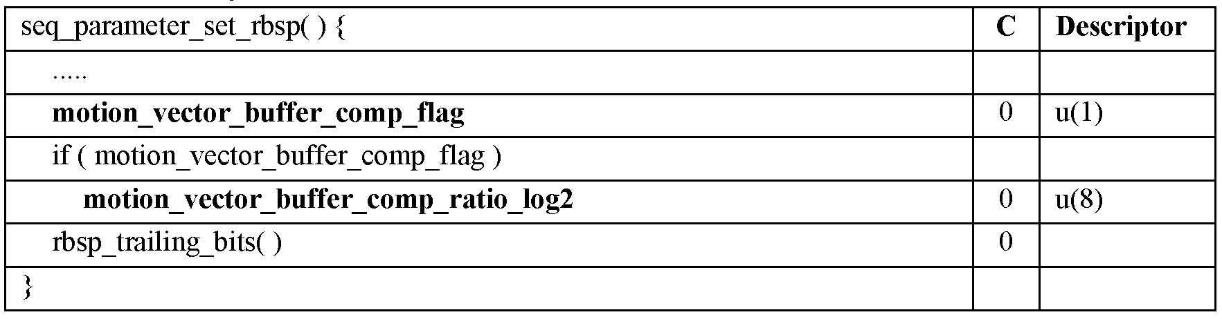
- the information is transmitted through a sequence parameter set (SPS) as shown in Table 2.
- SPS sequence parameter set
- motion_vector_buffer_comp_flag 1
- a motion vector buffer compression process is performed.
- motion_vector_buffer_comp_ratio_log2 represents the compression ratio of the motion vector buffer compression process. If motion_vector_buffer_comp_ratio_log2 does not exist, motion_vector_buffer_comp_ratio_log2 is inferred to be 0, and the motion vector buffer compression ratio is expressed as in Equation (1).
- the size of the required memory space and the memory access bandwidth can be reduced by using the spatial correlation of the motion vector.
- the above method of lowering the spatial resolution of the motion vector does not limit the dynamic range of the motion vector.
- the size of the memory space required in the above example is reduced to about 0.8 Mbytes.
- the required memory space can be further reduced to 0.37 Mbytes.
- the present invention limits the dynamic range of the motion vectors in order to reduce the size of the memory space required to store the motion vectors and the memory access bandwidth required to retrieve data from the memory.
- the motion vector of the reference picture with limited dynamic range may be used as a temporal motion vector in a block to be encoded / decoded.
- the dynamic range means a section between minimum and maximum values that a negative or positive component of a motion vector can have, and a bit depth indicates a size of a space required to store a motion vector. It can also mean bit width.
- a motion vector refers to a motion vector of a reference picture, that is, a temporal motion vector.
- Each component of the motion vector is represented by the minimum or maximum value of the dynamic range when it is out of the dynamic range. For example, when the X component of the motion vector is 312 and the maximum value of the dynamic range of each component of the motion vector is 256, the X component of the motion vector is limited to 256.
- each component of the motion vector is 16 bits and the motion vector is (-36, 24), limiting the bit depth of each component of the motion vector to 6 bits,
- the component has a dynamic range of -32 to +31 so that the motion vector is represented by (-32, 24) within the dynamic range.
- the bit depth of each component of the motion vector is 16 bits and the motion vector is (-49, 142)
- the bit depth of each component of the motion vector is limited to 9 bits
- the component has a dynamic range of -256 to +255 so that the motion vector is represented as (-49, 142) without change.
- the bit depth may be reduced from 13 bits to 8 bits.
- Each component of the temporal motion vector is clipped as shown in Equations 2 and 3 to be stored with a bit depth of N bit (s). Where N is a positive integer.
- MV_X is the X component of the motion vector
- MV_Y is the Y component of the motion vector
- min (a, b) outputs the smaller value of a and b
- max (a, b) is the larger value of a and b.
- clippedMV_X and clippedMV_Y are X and Y components of the cut temporal motion vectors, respectively, and are stored in the memory and used as temporal motion vectors of the block to be encoded / decoded.
- an image reconstructed by an encoding device and / or a decoding device performs an in-loop filtering process such as a deblocking filter or an adaptive loop filter.
- an in-loop filtering process such as a deblocking filter or an adaptive loop filter.
- the motion vector of the reference picture is stored by limiting the dynamic range of the motion vector.
- the reconstructed image buffer may mean the reference picture buffer of FIG. 1 or 2.
- the process of cutting each component of the motion vector is performed when the slice type (slice_type) is not an I picture.
- the motion vector cutting process is performed in a treeblock or largest coding unit (LCU) after the filtering process is completed.
- LCU largest coding unit
- the inputs of the motion vector cutting process are (xP, yP), which are the upper left pixel positions of the prediction unit in the current picture, and the motion vector matrices MvL0 and MvL1, and the outputs are the truncated motion vector matrices CMvL0 and CMvL1.
- Equations 4 to 7 are performed on the matrices MvL0, MvL1, CMvL0, and CMvL1.
- TMVBitWidth represents the bit depth of the motion vector
- Clip3 (a, b, c) means a function of cutting c such that it exists within a range between a and b.
- 5 through 8 are flowcharts illustrating a method of storing a motion vector of a reference picture.
- a motion vector of a reference picture may be stored by using an image buffer for storing a reconstructed image and a motion vector buffer for storing a motion vector.
- the reconstructed image is subjected to the in-loop filtering process (S510), and the motion vector is stored with the dynamic range limited (S520) and stored (S540).
- the image buffer and the motion vector buffer are used together, and the motion vector is stored through the dynamic range limitation process (S620) and the spatial resolution reduction process (S630) (S640).
- the reconstructed image is stored in the image buffer through an in-loop filtering process (S710), and the motion vector is stored in the motion vector buffer due to the limited dynamic range (S720). do.
- the reconstructed image is stored in the image buffer through an in-loop filtering process (S810), and a motion vector includes a dynamic range limitation process (S820) and a spatial resolution reduction process (S830). It is stored through (S850).
- the dynamic range limitation process (S620, S820) and the spatial resolution reduction process (S630, S830) are not limited to the order and may be changed.
- the dynamic range for each component of the motion vector can be limited differently. For example, it is possible to limit only one of the dynamic range of the X component and the dynamic range of the Y component, or limit the dynamic range of the Y component more than the dynamic range of the X component.
- the limited dynamic range of the motion vector is transmitted through a sequence parameter set, a picture parameter set (PPS), or a slice header, and the decoding apparatus performs a dynamic motion of a temporal motion vector in a sequence, picture, or slice. Perform the same limitation of the range.
- a bit depth which is a size of a memory space required to store a motion vector represented within a dynamic range range, may be transmitted together.
- the temporal motion vector can be efficiently adapted to the motion characteristics of the image by using the dynamic range transmitted through a sequence parameter, a picture parameter set, or a slash header. You can also save it as
- the motion vector may be quantized and stored.
- Quantization methods include uniform quantization in which the step size is equal, non-uniform quantization in which the step size is not equal, and the like.
- the step size of the quantization is set to a fixed value previously promised by the encoding apparatus and the decoding apparatus, or is a sequence parameter set. It is transmitted from the encoding apparatus to the decoding apparatus through a picture parameter set or a slice header.
- quantized motion vectors are used as they are or inverse quantized.
- 9 is an example of quantizing a motion vector. Referring to FIG. 9, when the motion vector has component values of 32 to 48, the motion vector is quantized to 40.
- the motion vector may be stored with limited representation resolution.
- the expression resolution means integer pixel units (1 pixel unit) and fractional pixel units (1/2 pixel unit, 1/4 pixel unit, etc.).
- the resolution of the motion vector processed in units of 1/4 pixels may be stored as an integer pixel.
- the representation resolution of the motion vector is set to a fixed value previously promised by the encoding apparatus and the decoding apparatus, or transmitted from the encoding apparatus to the decoding apparatus through a sequence parameter set, a picture parameter set, or a slice header.
- the dynamic range limitation process, the spatial resolution reduction process, and the quantization process of the motion vectors may be performed on only some of the temporal motion vectors stored in the memory.
- information about the dynamic range of the motion vector may be added and stored in the memory.
- a flag of 1 may be additionally stored
- a dynamic range of the motion vector is -32 to +31
- a flag of 0 may be additionally stored.
- the flag information may be stored together with the motion vector or in a memory other than the memory in which the motion vector is stored.
- the flag information and the motion vector are stored in different memories, the flag information can be randomly accessed when figuring out which dynamic range a particular motion vector is stored.
- information on which dynamic range some motion vectors are stored may be transmitted through a sequence parameter set, a picture parameter set, or a slice header, so that the decoder may operate in the same manner as the encoder.
- information about the block size of the motion vector may be added and stored in the memory.
- a flag of 1 may be additionally stored, and when it is 16x16, a flag of 0 may be additionally stored.
- the flag information may be stored together with the motion vector or in a memory other than the memory in which the motion vector is stored.
- the flag information can be randomly accessed when figuring out what block size the specific motion vector is stored.
- information on what block size is stored in some motion vectors may be transmitted through a sequence parameter set, a picture parameter set, or a slice header, so that the decoder may operate in the same manner as the encoder.
- information about the precision of the motion vector may be added and stored in the memory.
- a flag of 1 is additionally stored.
- a flag of 0 can be additionally stored.
- the flag information may be stored together with the motion vector or in a memory other than the memory in which the motion vector is stored.
- the flag information and the motion vector are stored in different memories, the flag information can be arbitrarily accessed when figuring out which step size the specific motion vector is quantized and stored.
- information on whether some motion vectors are quantized and stored in what step size may be transmitted through a sequence parameter set, a picture parameter set, or a slice header, so that the decoder may operate in the same manner as the encoder.
- the motion information when the motion information is stored in the memory, the spatial resolution of the motion vector may be reduced and stored.
- the motion information includes inter prediction mode information indicating a reference picture index, a motion vector, uni-direction, or bi-direction required for inter prediction, and a reference picture list.
- Information including at least one of prediction mode information regarding whether the information is encoded in the intra prediction mode or the inter prediction mode.
- the motion information of the prediction unit having the largest partition size among a plurality of pieces of motion information of a specific region may be stored in the memory as representative motion information.
- the specific region may include the region within the encoding / decoding target block and the region of the neighboring block.
- the specific area may be an area including a block in which motion information is stored when a picture or slice is divided into a predetermined size.
- the representative motion information may be stored in the memory after excluding the motion information encoded by the motion information merging method, the encoding information skip method, and the like among the plurality of motion information included in the specific region.
- the most frequently generated motion information among the plurality of motion information included in the specific region may be stored in the memory as the representative motion information.
- the number of occurrences of motion information may be calculated for each block size.
- motion information of a specific location may be stored among a plurality of motion information included in a specific area.
- the specific position may be a position included in the specific region and may be a fixed position of the specific region.
- the specific position may be selected as one of a plurality. If a plurality of locations are used, priority may be determined for each location, and motion information may be stored in a memory according to the priority.
- motion information when storing a plurality of pieces of motion information included in a specific region in a memory, motion information does not exist outside the boundary of a block coded in an intra prediction mode, a block coded in a PCM mode, a slice, or a picture boundary. Therefore, the motion information of the corresponding position may not be stored in the memory.
- the motion information of the same position block, the motion information of the first coded block, or the motion information of the neighboring block is the motion of the corresponding position.
- the specific position may be one sample position or a position of a block in a block existing around the encoding / decoding target block.
- a median or average value of motion information of inter prediction coded blocks around the location may be stored in a memory.
- an average value of motion information of neighboring blocks of the location may be stored in a memory.
- the motion vector is the reference picture index.
- the image may be resized according to a reference picture list, inter prediction mode information, a picture display count, and the like.
- the stored motion information can be obtained.
- motion information of a position corresponding to the position of the encoding / decoding target block in the reference picture may be obtained.
- a position corresponding to the position of the encoding / decoding object block in the reference picture may be a fixed position in a specific region or a position relative to the position of the encoding / decoding object block.
- block X represents a block to be encoded / decoded in the pictures 1010, 1110, 1210, and 1310 to be encoded / decoded
- blocks A, Block B, Block C, Block D, and Block E are encoded / decoded.
- the recovery block located in the periphery of the target block is shown.
- the blocks T in the reference pictures 1020, 1120, 1220, and 1320 indicate equivalent position blocks corresponding to the blocks to be encoded / decoded.
- a block Y in the reference picture 1320 of FIG. 13 indicates a block corresponding to a position other than a block to be encoded / decoded.
- motion information corresponding to a position corresponding to a left upper pixel position among positions of an encoding / decoding target block X in a reference picture may be obtained.
- motion information corresponding to a position corresponding to a pixel position among the positions of the encoding / decoding target block X in the reference picture may be obtained.
- motion information corresponding to a position corresponding to a lower right pixel position among positions of an encoding / decoding target block X in a reference picture may be obtained.
- motion information corresponding to a position corresponding to a position other than the encoding / decoding target block X in the reference picture may be obtained.
- motion information stored in a memory that is, motion information of a reference picture
- encoding / decoding methods such as motion vector prediction, improved motion vector prediction, motion information merging, and motion information merge skip may be performed.
- a motion vector is stored in a memory using at least one of a dynamic range limitation method of a motion vector, a spatial resolution reduction method of the motion vector, a quantization method of the motion vector, and a method of reducing the representation resolution of the motion vector, and the stored motion vector is encoded / It can be used for motion vector prediction and motion information merging of a decoding object block.
- TMVbitWidth represents the bit width of the temporal motion vector stored in the memory.
- the inputs of the temporal motion vector derivation process are (xP, yP), the upper left pixel position of the prediction unit in the current picture, nPSW and nPSH, which are the horizontal and vertical lengths of the luminance prediction unit, and refIdxLX, which is the reference picture index of the current prediction unit partition.
- the output is the motion vector prediction value mxLXCl and the availableFlagLXCol flag.
- RefPicOrderCnt (pic, refidx, LX) is a function that outputs PicOrderCnt of the reference picture RefPicListX [refidx] of pic. Where X can be 0 or 1. PicOrderCnt of the reference picture is present until the picture is treated as "non-exisiting".
- Clip3 (a, b, c) means a function of cutting c so that it is within a range between a and b.
- ColPic with a collocated partition is RefPicList1 [0] when slice_type is B-slice and collocated_from_l0_flag is 0; Otherwise, if the slice type is P-slice or collocated_from_l0_flag is 1, then RefPicList0 [0].
- colPu and colPu are derived in the following order.
- the lower right luminance component positions (xPRb, yPRb) of the current prediction unit are defined as in Equations 8 and 9 below.
- colPu is encoded in intra prediction mode or colPu does not exist
- Equations 10 and 11 The center luminance component positions (xPCtr, yPCtr) of the current prediction unit are defined as in Equations 10 and 11 below.
- colPu is set to a prediction unit including the position of ((xPCtr >> 4) ⁇ 4, (yPCtr >> 4) ⁇ 4) in colPic.
- mvLXCol and availableFlagLXCol are derived as follows.
- each component of mvLXCol is 0, and availableFlagLXCol is also 0.
- colPu is not encoded in the intra prediction mode, and if colPu exists, mvLXCol and refIdxCol are derived as follows.
- X becomes 0 or 1, and the following allocation process is performed.
- RefIdxColLX is assigned to RefIdxLX [xPCol] [yPCol].
- PicOrderCnt (colPic) is less than PicOrderCnt (currPic), RefPicOrderCnt (colPic, RefIdxColLX, LX) is greater than PicOrderCnt (currPic), or PicOrderCnt (colPic) is greater than PicOrderCnt (currPic) PrCic, If less than PicOrderCnt (currPic), MvXCross is assigned to 1.
- PicOrderCnt (colPic) is less than PicOrderCnt (currPic)
- RefPicOrderCnt (colPic, RefIdxColLX, LX) is less than or equal to PicOrderCnt (currPic)
- RefIdxColLX, LX is greater than or equal to PicOrderCnt (currPic)
- MvXCross is assigned to 1.
- the motion vector mvCol, the reference picture index refIdxCol, and ListCol are determined as MvL1 [xPCol] [yPCol], RefIdxColL1, and L1, respectively.
- Mv0Cross 0
- Mv1Cross 1
- Mv0Cross and Mv1Cross are the same, and the reference picture list is L1.
- the motion vectors mvCol, reference picture index refIdxCol, and ListCol are determined to be MvL0 [xPCol] [yPCol], RefIdxColL0, L0, respectively.
- PicOrderCnt (colPic) -RefPicOrderCnt (colPic, refIdxCol, ListCol) is equal to PicOrderCnt (currPic) -RefPicOrderCnt (currPic, refIdxLX, LX)
- Equation 17 td and tb are the same as in Equation 17 and Equation 18.
- mvLXCol is derived as a scaled version of the motion vector mvCol.
- Equations 15 and 16 may be replaced by Equations 19 and 20, respectively.
- TMVBitWidth in the above-described temporal motion vector derivation process may be transmitted from the encoding apparatus to the decoding apparatus through a sequence parameter set, a picture parameter set, or a slice header.
- Bit_width_temporal_motion_vector_minus8 in Table 5 represents the bit width of the temporal motion vector component. If bit_width_temporal_motion_vector_minus8 does not exist, it is inferred to be 0, and the bit width of the temporal motion vector component is expressed by Equation 21.
- motion_vector_buffer_comp_flag 1
- a motion vector buffer compression process is performed.
- motion_vector_buffer_comp_ratio_log2 represents the compression ratio of the motion vector buffer compression process. If motion_vector_buffer_comp_ratio_log2 does not exist, it is inferred to be 0, and the motion vector buffer compression ratio is expressed by Equation 22.
- bit_depth_temporal_motion_vector_constraint_flag 1
- bit_depth_temporal_motion_vector_constraint_flag 1
- bit_depth_temporal_motion_vector_minus8 represents the bit depth of a temporal motion vector. If bit_depth_temporal_motion_vector_minus8 does not exist, it is inferred to be 0, and the bit depth of the temporal motion vector is represented by Equation 23.
- bit_depth_temporal_motion_vector_constraint_flag 1
- bit_depth_temporal_motion_vector_constraint_flag 1
- bit_depth_temporal_motion_vector_minus8 represents the bit depth of a temporal motion vector. If bit_depth_temporal_motion_vector_minus8 does not exist, it is inferred to be 0, and the bit depth of the temporal motion vector is expressed as in Equation (24).
- Bit_depth_temporal_motion_vector_minus8 in Table 8 represents the bit depth of the temporal motion vector. If bit_depth_temporal_motion_vector_minus8 does not exist, it is inferred to be 0, and the bit depth of the temporal motion vector is expressed as in Equation 25.
- bit_depth_temporal_motion_vector_constraint_flag 1
- bit_depth_temporal_motion_vector_constraint_flag 1
- bit_depth_temporal_motion_vector_x_minus8 represents the X component bit depth of the temporal motion vector. If bit_depth_temporal_motion_vector_x_minus8 does not exist, it is inferred to be 0, and the bit depth of the temporal motion vector is expressed by Equation 26.
- bit_depth_temporal_motion_vector_y_minus8 represents the Y component bit depth of the temporal motion vector. If bit_depth_temporal_motion_vector_x_minus8 does not exist, it is inferred to be 0, and the bit depth of the temporal motion vector is expressed by Equation 27.
- motion_vector_buffer_comp_flag 1
- a motion vector buffer compression process is performed.
- motion_vector_buffer_comp_ratio_log2 represents the compression ratio of the motion vector buffer compression process. If motion_vector_buffer_comp_ratio_log2 does not exist, it is inferred to be 0, and the motion vector buffer compression ratio is expressed by Equation 28.
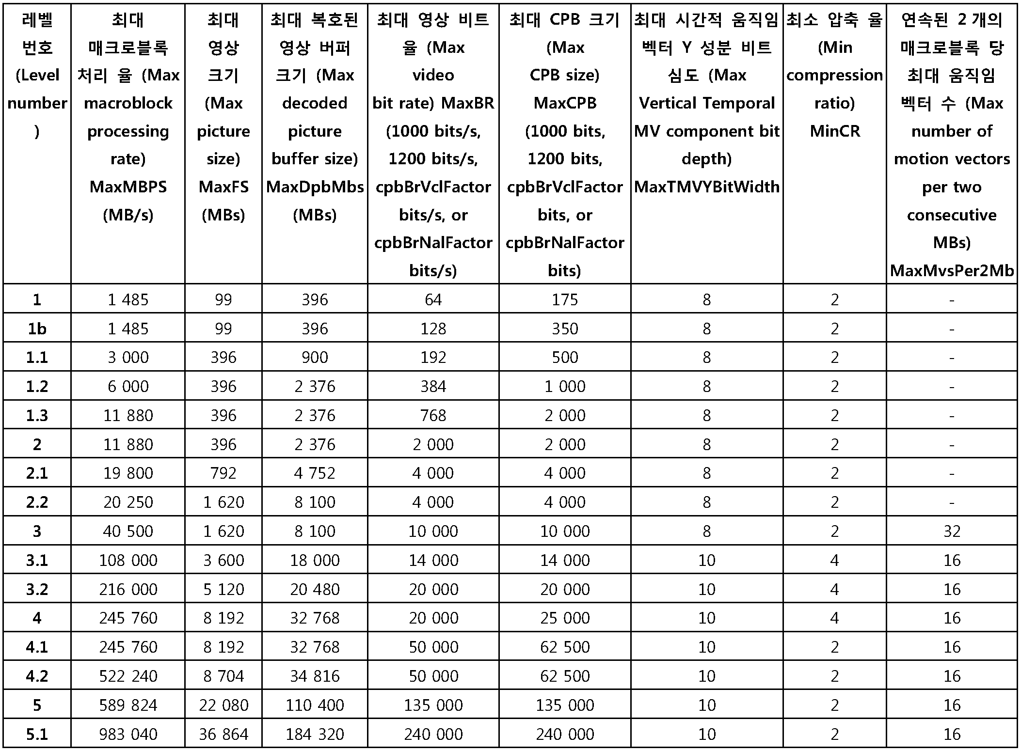
- the dynamic range of the temporal motion vector is not transmitted through a sequence parameter set, a picture parameter set, or a slice header, but may be defined through a level of an image codec.
- the encoding apparatus and the decoding apparatus may determine the limited dynamic range of the motion vector using the level information.
- the dynamic range and / or bit depth of each of the X and Y components of the motion vector may be defined differently, and the minimum and maximum values of the respective components may be defined.
- Table 11 and Table 12 show an example of defining TMVBitWidth at the level in the above-described temporal motion vector derivation process.
- TMVBitWidth is set to MaxTMVBitWidth defined in the level. At this time, MaxTMVBitWidth represents the maximum bit width of the motion vector when the temporal motion vector is stored in the memory.
- TMVBitWidth is defined in the level and may transmit a sequence parameter set, a picture parameter set, or a slice header with a difference (delta value) from the defined value. That is, TMVBitWidth may be set to a value obtained by adding a difference transmitted in a sequence parameter set, a picture parameter set, or a slice header to MaxTMVBitWidth defined in the level. In this case, TMVBitWidth represents the bit width of the motion vector when the temporal motion vector is stored in the memory.
- Delta_bit_width_temporal_motion_vector_minus8 in Table 13 represents a difference in bit widths of temporal motion vector components. If delta_bit_width_temporal_motion_vector_minus8 does not exist, it is inferred to be 0, and the bit width of the temporal motion vector component is expressed as in Equation 29.
- the dynamic range of each component of the temporal motion vector may be defined in the level.
- bit widths of components of each temporal motion vector may be defined in the level.
- bit width of the temporal motion vector Y component may be defined in the level.
- the dynamic range of the temporal motion vector may be defined as a fixed value previously promised by the encoding apparatus and the decoding apparatus, or may be stored in the form of a fixed bit depth without transmitting information on the limitation of the motion vector.
- TMVBitWidth When TMVBitWidth is fixedly used at the same value in the encoding apparatus and the decoding apparatus, TMVBitWidth may be a positive integer such as 4, 6, 8, 10, 12, 14, 16, or the like. In this case, TMVBitWidth represents the bit width of the motion vector when the temporal motion vector is stored in the memory.
- the image encoding method includes a cutting step S1410, a storing step S1420, and an encoding step S1430.
- the image encoding apparatus and / or the decoding apparatus cuts the motion vector of the reference picture into a predetermined dynamic range (S1410).
- a predetermined dynamic range S1410
- I. Motion vector cutting process motion vectors outside the dynamic range are represented by the minimum or maximum value of the dynamic range. Therefore, as described above through “IV. Information transmission method for cutting a temporal motion vector in a decoding apparatus” and "V. Definition of a dynamic range through the level of an image codec", the level and / or sequence parameter of an image codec The bit depth may be limited through a set or the like, or the dynamic range may be limited through a level of an image codec to cut a motion vector of a reference picture into a predetermined dynamic range.
- the image encoding apparatus and / or the decoding apparatus stores the motion vector of the truncated reference picture in the buffer as described above through "II. Motion vector storing process" (S1420).
- the motion vector may be stored in a buffer with or separately from the reconstructed image.
- the image encoding apparatus encodes the motion vector of the encoding target block by using the stored motion vector of the reference picture (S1430).
- the motion vector of the encoding target block may be a motion vector of the reference picture, that is, a temporal motion vector, as well as the motion vector of the neighboring block adjacent to the encoding target block.
- each component of the motion vector of the reference picture may be cut in each dynamic range.
- a method of compressing the motion vector of the reference picture as well as a method of restricting the dynamic range of the motion vector of the reference picture may be used.
- a flag indicating the level and / or a sequence parameter set of an image codec and the like and a parameter thereof may be defined.
- a coding method such as motion vector prediction, enhanced motion vector prediction, motion information merging, and motion information merge skip may be performed.
- the image decoding method includes a cutting step S1510, a storing step S1520, a deriving step S1530, and a decoding step S1540.
- the cutting step S1510 and the storing step S1520 of FIG. 15 are the cutting step S1410 and the storing step S1420 of FIG. 14 using the aforementioned "I. motion vector cutting process” and "II. Motion vector storing process”. Similar to In addition, the derivation step S1530 of FIG. 15 uses the aforementioned "III. Motion vector derivation process" and is symmetrical to the encoding step S1430 of FIG. Therefore, detailed description thereof will be omitted.
- the image decoding apparatus performs inter prediction decoding using the motion vector of the decoding object block (S1540).
- the image decoding apparatus stores the motion vector in the memory using at least one of a dynamic range limitation method of the motion vector, a spatial resolution reduction method of the motion vector, a quantization method of the motion vector, and a method of reducing the representation resolution of the motion vector, and stores the stored motion vector.
- the vector may be used for motion vector prediction and motion information merging of the decoding object block.
- a decoding method such as motion vector prediction, enhanced motion vector prediction, motion information merging, motion information merge skip, and the like may be performed.
Landscapes
- Engineering & Computer Science (AREA)
- Multimedia (AREA)
- Signal Processing (AREA)
- Compression Or Coding Systems Of Tv Signals (AREA)
Abstract
Description

| MV1-X | MV1-Y | MV2-X | MV2-Y | MV3-X | MV3-Y | MV4-X | MV4-Y |
| MV5-X | MV5-Y | MV6-X | MV6-Y | MV7-X | MV7-Y | MV8-X | MV8-Y |
| MV9-X | MV9-Y | MV10-X | MV10-Y | MV11-X | MV11-Y | MV12-X | MV12-Y |
| MV1-X | MV1-Y | MV2-X | MV2-Y | MV3-X | MV3-Y | MV4-X | MV4-Y |
| MV5-X | MV5-Y | MV6-X | MV6-Y | MV7-X | MV7-Y | MV8-X | MV8-Y |
| MV9-X | MV9-Y | MV10-X | MV10-Y | MV11-X | MV11-Y | MV12-X | MV12-Y |
| MV13-X | MV13-Y | MV14-X | MV14-Y | MV15-X | MV15-Y | MV16-X | MV16-Y |
| MV17-X | MV17-Y | MV18-X | MV18-Y | MV19-X | MV19-Y | MV20-X | MV20-Y |
| MV21-X | MV21-Y | MV22-X | MV22-Y | MV23-X | MV23-Y | MV24-X | MV24-Y |


Claims (20)
- 참조 픽쳐의 움직임 벡터를 소정의 다이내믹 레인지로 절삭하여 절삭된 움직임 벡터를 생성하는 단계;상기 절삭된 움직임 벡터를 버퍼에 저장하는 단계; 및상기 버퍼에 저장된 움직임 벡터를 이용하여 부호화 대상 블록의 움직임 벡터를 부호화 단계를 포함하는 것을 특징으로 하는 영상 부호화 방법.
- 제 1항에 있어서,상기 다이내믹 레인지는 영상 코덱의 레벨에 의해 정의되는 것을 특징으로 하는 영상 부호화 방법.
- 제 1항에 있어서,상기 다이내믹 레인지는 소정의 비트 심도에 의해 결정되고,상기 비트 심도는 영상 코덱의 레벨에 의해 정의되는 것을 특징으로 하는 영상 부호화 방법.
- 제 1항에 있어서,상기 참조 픽쳐의 움직임 벡터의 X 성분과 Y 성분은 서로 다른 다이내믹 레인지로 절삭되는 것을 특징으로 하는 영상 부호화 방법.
- 참조 픽쳐의 움직임 벡터를 소정의 다이내믹 레인지로 절삭하여 절삭된 움직임 벡터를 생성하는 단계;상기 절삭된 움직임 벡터를 버퍼에 저장하는 단계;상기 버퍼에 저장된 움직임 벡터를 이용하여 복호화 대상 블록의 움직임 벡터를 도출하는 단계; 및상기 복호화 대상 블록의 움직임 벡터를 이용하여 인터 예측 복호화를 수행하는 단계를 포함하는 영상 복호화 방법.
- 제 5항에 있어서,상기 다이내믹 레인지는 영상 코덱의 레벨에 의해 정의되는 것을 특징으로 하는 영상 복호화 방법.
- 제 5항에 있어서,상기 다이내믹 레인지는 소정의 비트 심도에 의해 결정되고,상기 비트 심도는 영상 코덱의 레벨에 의해 정의되는 것을 특징으로 하는 영상 복호화 방법.
- 제 5항에 있어서,상기 다이내믹 레인지는 소정의 비트 심도에 의해 결정되고,상기 비트 심도는 영상 부호화 장치로부터 전송되는 시퀀스 파라미터 셋을 통해 획득되는 것을 특징으로 하는 영상 복호화 방법.
- 제 8항에 있어서,상기 시퀀스 파라미터 셋은상기 참조 픽쳐의 움직임 벡터가 절삭되었는지를 나타내는 플래그 및상기 비트 심도를 획득하기 위한 파라미터를 포함하는 것을 특징으로 하는 영상 복호화 방법.
- 제 9항에 있어서,상기 영상 복호화 방법은 상기 참조 픽쳐의 움직임 벡터를 압축하는 단계를 더 포함하고,상기 시퀀스 파리미터 셋은상기 참조 픽쳐의 움직임 벡터가 압축되었는지를 나타내는 플래그 및상기 참조 픽쳐의 움직임 벡터의 압축 비율을 획득하기 위한 파라미터를 더 포함하는 것을 특징으로 하는 영상 복호화 방법.
- 제 5항에 있어서,상기 영상 복호화 방법은 상기 참조 픽쳐의 움직임 벡터의 표현 해상도를 제한하는 단계를 더 포함하는 것을 특징으로 하는 영상 복호화 방법.
- 제 5항에 있어서,상기 절삭된 움직임 벡터는 우선순위에 따라 저장되는 것을 특징으로 하는 영상 복호화 방법.
- 제 5항에 있어서,상기 절삭된 움직임 벡터는 인터 예측 모드로 부호화된 블록의 움직임 벡터인 것을 특징으로 하는 영상 복호화 방법.
- 제 5 항에 있어서,상기 영상 복호화 방법은 상기 참조 픽쳐의 움직임 벡터에 대한 스케일링(scaling)을 수행하는 단계를 더 포함하는 것을 특징으로 하는 영상 복호화 방법.
- 제 5항에 있어서,상기 참조 픽쳐의 움직임 벡터의 X 성분과 Y 성분은 서로 다른 다이내믹 레인지로 절삭되는 것을 특징으로 하는 영상 복호화 방법.
- 제 15항에 있어서,상기 X 성분의 다이내믹 레인지와 상기 Y 성분의 다이내믹 레인지는 영상 코덱의 레벨에 의해 정의되는 것을 특징으로 하는 영상 복호화 방법.
- 참조 픽쳐를 저장하는 참조 픽쳐 버퍼; 및상기 참조 픽쳐 및 상기 참조 픽쳐의 움직임 벡터를 이용하여 예측 블록을 생성하는 움직임 보상부를 포함하되,상기 참조 픽쳐의 움직임 벡터는 소정의 다이내믹 레인지로 절삭된 것을 특징으로 하는 영상 복호화 장치.
- 제 17항에 있어서,상기 다이내믹 레인지는 영상 코덱의 레벨에 의해 정의되는 것을 특징으로 하는 영상 복호화 장치.
- 제 17항에 있어서,상기 다이내믹 레인지는 소정의 비트 심도에 의해 결정되고,상기 비트 심도는 영상 코덱의 레벨에 의해 정의되는 것을 특징으로 하는 영상 복호화 장치.
- 제 17항에 있어서,상기 다이내믹 레인지는 소정의 비트 심도에 의해 결정되고,상기 비트 심도는 영상 부호화 장치로부터 전송되는 시퀀스 파라미터 셋을 통해 획득되는 것을 특징으로 하는 영상 복호화 장치.
Priority Applications (21)
| Application Number | Priority Date | Filing Date | Title |
|---|---|---|---|
| BR122020015452-7A BR122020015452B1 (pt) | 2011-01-31 | 2012-01-31 | Aparelho de decodificação de imagem |
| BR122014018140-0A BR122014018140B1 (pt) | 2011-01-31 | 2012-01-31 | Método de decodificação de imagem |
| BR122020015455-1A BR122020015455B1 (pt) | 2011-01-31 | 2012-01-31 | Aparelho de decodificação de imagem |
| ES12742304T ES2899990T3 (es) | 2011-01-31 | 2012-01-31 | Método y aparato para codificar/decodificar imágenes usando un vector de movimiento |
| BR122020015411-0A BR122020015411B1 (pt) | 2011-01-31 | 2012-01-31 | Aparelho de decodificação de imagem |
| RU2013140464/08A RU2586017C2 (ru) | 2011-01-31 | 2012-01-31 | Способ и устройство для кодирования/декодирования изображений с использованием вектора движения |
| EP21176802.3A EP3930332A1 (en) | 2011-01-31 | 2012-01-31 | Apparatus for encoding/decoding images using a motion vector |
| DK12742304.4T DK2672708T3 (da) | 2011-01-31 | 2012-01-31 | Fremgangsmåde og apparat til kodning/afkodning af billeder under anvendelse af en bevægelsesvektor |
| SI201231970T SI2672708T1 (sl) | 2011-01-31 | 2012-01-31 | Postopek in naprava za kodiranje/dekodiranje slik z uporabo vektorja gibanja |
| PL12742304T PL2672708T3 (pl) | 2011-01-31 | 2012-01-31 | Sposób i urządzenie do kodowania/dekodowania obrazów z wykorzystaniem wektora ruchu |
| JP2013551919A JP5911890B2 (ja) | 2011-01-31 | 2012-01-31 | 動きベクトルを利用する映像符号化/復号化方法及び装置 |
| CA2826157A CA2826157C (en) | 2011-01-31 | 2012-01-31 | Method and apparatus for encoding/decoding images using a motion vector |
| US13/979,214 US10244252B2 (en) | 2011-01-31 | 2012-01-31 | Method and apparatus for encoding/decoding images using a motion vector |
| EP12742304.4A EP2672708B1 (en) | 2011-01-31 | 2012-01-31 | Method and apparatus for encoding/decoding images using a motion vector |
| CN201280015709.8A CN103583044B (zh) | 2011-01-31 | 2012-01-31 | 用于使用运动向量来编码/解码图像的方法和设备 |
| BR112013019495-2A BR112013019495B1 (pt) | 2011-01-31 | 2012-01-31 | Aparelho de decodificação de imagem |
| US16/249,146 US10645411B2 (en) | 2011-01-31 | 2019-01-16 | Method and apparatus for encoding/decoding images using a motion vector |
| US16/830,236 US12003753B2 (en) | 2011-01-31 | 2020-03-25 | Method and apparatus for encoding/decoding images using a motion vector |
| US17/538,797 US12028545B2 (en) | 2011-01-31 | 2021-11-30 | Method and apparatus for encoding/decoding images using a motion vector |
| US18/630,834 US12301859B2 (en) | 2011-01-31 | 2024-04-09 | Method and apparatus for encoding/decoding images using a motion vector |
| US19/172,277 US20250234030A1 (en) | 2011-01-31 | 2025-04-07 | Method and apparatus for encoding/decoding images using a motion vector |
Applications Claiming Priority (10)
| Application Number | Priority Date | Filing Date | Title |
|---|---|---|---|
| KR20110009636 | 2011-01-31 | ||
| KR10-2011-0009636 | 2011-01-31 | ||
| KR10-2011-0019166 | 2011-03-03 | ||
| KR20110019166 | 2011-03-03 | ||
| KR10-2011-0050853 | 2011-05-27 | ||
| KR1020110050853A KR20120088488A (ko) | 2011-01-31 | 2011-05-27 | 시간적 움직임 벡터 저장 방법 및 그 장치 |
| KR1020110065707A KR20120088494A (ko) | 2011-01-31 | 2011-07-01 | 시간적 움직임 벡터 저장 방법 및 그 장치 |
| KR10-2011-0065707 | 2011-07-01 | ||
| KR1020120010096A KR101428030B1 (ko) | 2011-01-31 | 2012-01-31 | 움직임 벡터를 이용한 영상 복호화 장치 |
| KR10-2012-0010096 | 2012-01-31 |
Related Child Applications (2)
| Application Number | Title | Priority Date | Filing Date |
|---|---|---|---|
| US13/979,214 A-371-Of-International US10244252B2 (en) | 2011-01-31 | 2012-01-31 | Method and apparatus for encoding/decoding images using a motion vector |
| US16/249,146 Continuation US10645411B2 (en) | 2011-01-31 | 2019-01-16 | Method and apparatus for encoding/decoding images using a motion vector |
Publications (2)
| Publication Number | Publication Date |
|---|---|
| WO2012105807A2 true WO2012105807A2 (ko) | 2012-08-09 |
| WO2012105807A3 WO2012105807A3 (ko) | 2012-12-13 |
Family
ID=46873758
Family Applications (1)
| Application Number | Title | Priority Date | Filing Date |
|---|---|---|---|
| PCT/KR2012/000770 Ceased WO2012105807A2 (ko) | 2011-01-31 | 2012-01-31 | 움직임 벡터를 이용한 영상 부호화/복호화 방법 및 장치 |
Country Status (16)
| Country | Link |
|---|---|
| US (6) | US10244252B2 (ko) |
| EP (2) | EP3930332A1 (ko) |
| JP (8) | JP5911890B2 (ko) |
| KR (5) | KR20120088488A (ko) |
| CN (11) | CN108124162B (ko) |
| BR (5) | BR122020015411B1 (ko) |
| CA (3) | CA3050903C (ko) |
| DK (1) | DK2672708T3 (ko) |
| ES (1) | ES2899990T3 (ko) |
| HK (1) | HK1251838A1 (ko) |
| HU (1) | HUE056876T2 (ko) |
| PL (1) | PL2672708T3 (ko) |
| PT (1) | PT2672708T (ko) |
| RU (1) | RU2586017C2 (ko) |
| SI (1) | SI2672708T1 (ko) |
| WO (1) | WO2012105807A2 (ko) |
Cited By (1)
| Publication number | Priority date | Publication date | Assignee | Title |
|---|---|---|---|---|
| CN104704836A (zh) * | 2012-10-03 | 2015-06-10 | 联发科技股份有限公司 | 三维视频编码的运动数据缓存减少方法及装置 |
Families Citing this family (48)
| Publication number | Priority date | Publication date | Assignee | Title |
|---|---|---|---|---|
| KR20120088488A (ko) | 2011-01-31 | 2012-08-08 | 한국전자통신연구원 | 시간적 움직임 벡터 저장 방법 및 그 장치 |
| US10003817B2 (en) * | 2011-11-07 | 2018-06-19 | Microsoft Technology Licensing, Llc | Signaling of state information for a decoded picture buffer and reference picture lists |
| US9313500B2 (en) | 2012-09-30 | 2016-04-12 | Microsoft Technology Licensing, Llc | Conditional signalling of reference picture list modification information |
| US10015515B2 (en) * | 2013-06-21 | 2018-07-03 | Qualcomm Incorporated | Intra prediction from a predictive block |
| CN105874801B (zh) * | 2014-01-08 | 2019-11-08 | 索尼公司 | 解码设备和解码方法、以及编码设备和编码方法 |
| KR102105606B1 (ko) | 2014-06-02 | 2020-05-04 | 한국전자통신연구원 | 데이터 압축 장치 |
| CA2961681C (en) * | 2014-09-30 | 2022-08-09 | Hfi Innovation Inc. | Method of adaptive motion vetor resolution for video coding |
| CN115002455B (zh) * | 2015-06-05 | 2025-03-25 | 杜比实验室特许公司 | 图像编码和解码方法和图像解码设备 |
| JP2018533286A (ja) * | 2015-09-23 | 2018-11-08 | エルジー エレクトロニクス インコーポレイティド | 画像の符号化/復号化方法及びこれのために装置 |
| KR20170058838A (ko) | 2015-11-19 | 2017-05-29 | 한국전자통신연구원 | 화면간 예측 향상을 위한 부호화/복호화 방법 및 장치 |
| WO2017086738A1 (ko) | 2015-11-19 | 2017-05-26 | 한국전자통신연구원 | 영상 부호화/복호화 방법 및 장치 |
| CN106954074B (zh) * | 2016-01-07 | 2019-12-20 | 青岛海信电器股份有限公司 | 一种视频数据处理方法和装置 |
| TWI669946B (zh) | 2016-02-09 | 2019-08-21 | 弗勞恩霍夫爾協會 | 用於圖像/視訊資料串流而允許有效可縮減性或有效隨機存取之技術 |
| CN105744275B (zh) * | 2016-02-22 | 2019-04-05 | 青岛海信电器股份有限公司 | 一种视频数据输入、输出方法和装置 |
| CN116567220A (zh) * | 2016-08-11 | 2023-08-08 | Lx 半导体科技有限公司 | 图像编码/解码设备和图像数据的发送设备 |
| US10827186B2 (en) * | 2016-08-25 | 2020-11-03 | Intel Corporation | Method and system of video coding with context decoding and reconstruction bypass |
| TWI797549B (zh) | 2017-04-21 | 2023-04-01 | 美商時美媒體公司 | 用於藉由預測運動向量及/或快取重複運動向量的玩家輸入運動補償的系統及方法 |
| KR20200019854A (ko) | 2017-04-21 | 2020-02-25 | 제니맥스 미디어 인크. | 게임-생성된 모션 벡터들을 위한 시스템들 및 방법들 |
| EP3616406B1 (en) * | 2017-05-18 | 2024-03-20 | HFI Innovation Inc. | Method and apparatus of motion vector constraint for video coding |
| EP3761643A4 (en) | 2018-02-28 | 2022-02-23 | Samsung Electronics Co., Ltd. | VIDEO DECODING METHOD AND APPARATUS, AND VIDEO ENCODING METHOD AND APPARATUS |
| KR102516233B1 (ko) * | 2018-04-02 | 2023-03-30 | 엘지전자 주식회사 | 움직임 벡터에 기반한 영상 코딩 방법 및 그 장치 |
| US10873748B2 (en) * | 2018-05-12 | 2020-12-22 | Qualcomm Incorporated | Storage of high precision motion vectors in video coding |
| CN117956182A (zh) | 2018-06-04 | 2024-04-30 | 华为技术有限公司 | 获取运动矢量的方法和装置 |
| CN110662037B (zh) | 2018-06-29 | 2022-06-28 | 北京字节跳动网络技术有限公司 | 运动信息共享的限制 |
| CA3105072A1 (en) | 2018-06-29 | 2020-01-02 | Vid Scale, Inc. | Adaptive control point selection for affine motion model based video coding |
| KR20200028856A (ko) | 2018-09-07 | 2020-03-17 | 김기백 | 인트라 예측을 이용한 영상 부호화/복호화 방법 및 장치 |
| CN119277097A (zh) * | 2018-09-17 | 2025-01-07 | 韩国电子通信研究院 | 图像编码/解码方法以及存储比特流的记录介质 |
| WO2020076838A1 (en) * | 2018-10-08 | 2020-04-16 | Beijing Dajia Internet Information Technology Co., Ltd. | Motion vector storage for video coding |
| KR102913706B1 (ko) * | 2018-11-16 | 2026-01-19 | 샤프 가부시키가이샤 | 비디오 코딩에서 모션 벡터 예측을 도출하기 위한 시스템들 및 방법들 |
| CN113039780B (zh) | 2018-11-17 | 2023-07-28 | 北京字节跳动网络技术有限公司 | 视频处理中用运动矢量差的Merge |
| CN113196773B (zh) * | 2018-12-21 | 2024-03-08 | 北京字节跳动网络技术有限公司 | 具有运动矢量差的Merge模式中的运动矢量精度 |
| CN113196771B (zh) | 2018-12-21 | 2023-12-22 | 北京字节跳动网络技术有限公司 | 基于运动矢量精度的运动矢量范围 |
| EP3844960B1 (en) * | 2018-12-29 | 2025-02-19 | Huawei Technologies Co., Ltd. | An encoder, a decoder and corresponding methods using compact mv storage |
| CN114208169B (zh) * | 2019-06-11 | 2024-10-18 | Lg电子株式会社 | 用于色度分量的图像解码方法及其装置 |
| AU2020297835B2 (en) | 2019-06-21 | 2025-09-11 | Samsung Electronics Co., Ltd. | Apparatus and method for encoding and decoding motion information by using neighboring motion information |
| CN114616826B (zh) | 2019-08-06 | 2026-04-28 | Op方案有限责任公司 | 基于帧类型的自适应分辨率管理的隐式标识 |
| WO2021026324A1 (en) * | 2019-08-06 | 2021-02-11 | Op Solutions | Adaptive resolution management prediction rescaling |
| MX2022001592A (es) * | 2019-08-06 | 2022-03-11 | Op Solutions Llc | Método de gestión de resolución adaptativa para reajuste de predicción. |
| WO2021026322A1 (en) | 2019-08-06 | 2021-02-11 | Op Solutions | Block-based adaptive resolution management |
| CN114503557B (zh) * | 2019-09-22 | 2025-09-16 | 寰发股份有限公司 | 视频数据预测方法和装置 |
| KR20220092962A (ko) | 2019-11-08 | 2022-07-04 | 오피 솔루션즈, 엘엘씨 | 적응적 크롭핑을 위한 방법들 및 시스템들 |
| CN120639972A (zh) * | 2019-12-23 | 2025-09-12 | Lg电子株式会社 | 图像编码方法、图像解码方法和比特流发送方法 |
| US11792438B2 (en) | 2020-10-02 | 2023-10-17 | Lemon Inc. | Using neural network filtering in video coding |
| KR102946615B1 (ko) | 2020-12-28 | 2026-04-01 | 삼성전자주식회사 | 반도체 집적회로 레이아웃의 확률적 취약점 검출 방법 및 이를 수행하는 컴퓨터 시스템 |
| US12022098B2 (en) * | 2021-03-04 | 2024-06-25 | Lemon Inc. | Neural network-based in-loop filter with residual scaling for video coding |
| US12206861B2 (en) * | 2022-01-12 | 2025-01-21 | Tencent America LLC | Motion vector restriction for out-of-frame boundary conditions |
| US12413759B2 (en) | 2023-05-08 | 2025-09-09 | Tencent America LLC | Extension to block adaptive weighted prediction |
| WO2026010413A1 (ko) * | 2024-07-03 | 2026-01-08 | 엘지전자 주식회사 | 영상 인코딩/디코딩 방법 및 장치, 그리고 비트스트림을 저장한 기록 매체 |
Family Cites Families (50)
| Publication number | Priority date | Publication date | Assignee | Title |
|---|---|---|---|---|
| US5262854A (en) | 1992-02-21 | 1993-11-16 | Rca Thomson Licensing Corporation | Lower resolution HDTV receivers |
| DE69838281T2 (de) * | 1997-06-25 | 2008-05-15 | Nippon Telegraph And Telephone Corp. | Bewegungsprädiktives bildkodierungsverfahren sowie speichermedium zur speicherung des entsprechenden programms |
| US7206346B2 (en) * | 1997-06-25 | 2007-04-17 | Nippon Telegraph And Telephone Corporation | Motion vector predictive encoding method, motion vector decoding method, predictive encoding apparatus and decoding apparatus, and storage media storing motion vector predictive encoding and decoding programs |
| JP2914448B2 (ja) | 1997-06-25 | 1999-06-28 | 日本電信電話株式会社 | 動きベクトル予測符号化方法および動きベクトル復号方法、予測符号化装置および復号装置、並びに、動きベクトルの予測符号化プログラムおよび復号プログラムを記録した記録媒体 |
| JPH11122624A (ja) * | 1997-10-16 | 1999-04-30 | Matsushita Electric Ind Co Ltd | ビデオデコーダ処理量を低減する方法および装置 |
| DE60228101D1 (de) * | 2001-09-12 | 2008-09-18 | Nxp Bv | Bewegungsschätzung und/oder kompensation |
| CN1266947C (zh) | 2001-12-25 | 2006-07-26 | 松下电器产业株式会社 | 活动图象压缩编码装置及运动矢量检测方法 |
| US7177356B2 (en) * | 2002-01-11 | 2007-02-13 | Webtv Networks, Inc. | Spatially transcoding a video stream |
| CN1666532A (zh) * | 2002-07-02 | 2005-09-07 | 松下电器产业株式会社 | 图像编码方法和图像解码方法 |
| US6744387B2 (en) | 2002-07-10 | 2004-06-01 | Lsi Logic Corporation | Method and system for symbol binarization |
| US20040057521A1 (en) | 2002-07-17 | 2004-03-25 | Macchina Pty Ltd. | Method and apparatus for transcoding between hybrid video CODEC bitstreams |
| CN101090499A (zh) * | 2002-07-17 | 2007-12-19 | 达丽星网络有限公司 | 在混合视频codec比特流之间进行码转换的方法和装置 |
| AU2003268563A1 (en) * | 2002-10-01 | 2004-04-23 | Thomson Licensing S.A. | Implicit weighting of reference pictures in a video decoder |
| US7499495B2 (en) * | 2003-07-18 | 2009-03-03 | Microsoft Corporation | Extended range motion vectors |
| US20070014359A1 (en) * | 2003-10-09 | 2007-01-18 | Cristina Gomila | Direct mode derivation process for error concealment |
| JP4591657B2 (ja) | 2003-12-22 | 2010-12-01 | キヤノン株式会社 | 動画像符号化装置及びその制御方法、プログラム |
| US7961963B2 (en) * | 2005-03-18 | 2011-06-14 | Sharp Laboratories Of America, Inc. | Methods and systems for extended spatial scalability with picture-level adaptation |
| KR101406156B1 (ko) * | 2006-02-02 | 2014-06-13 | 톰슨 라이센싱 | 움직임 보상 예측을 위한 적응 가중 선택 방법 및 장치 |
| US8494052B2 (en) | 2006-04-07 | 2013-07-23 | Microsoft Corporation | Dynamic selection of motion estimation search ranges and extended motion vector ranges |
| JP4712643B2 (ja) * | 2006-08-17 | 2011-06-29 | 富士通セミコンダクター株式会社 | フレーム間予測処理装置、フレーム間予測方法、画像符号化装置及び画像復号装置 |
| US20080165860A1 (en) | 2006-08-31 | 2008-07-10 | Zohair Sahraoui | H.264 Data processing |
| JP2008067194A (ja) * | 2006-09-08 | 2008-03-21 | Toshiba Corp | フレーム補間回路、フレーム補間方法、表示装置 |
| WO2008039857A2 (en) | 2006-09-26 | 2008-04-03 | Dilithium Networks Pty Ltd. | Method and apparatus for compressed video bitstream conversion with reduced-algorithmic-delay |
| KR101365574B1 (ko) | 2007-01-29 | 2014-02-20 | 삼성전자주식회사 | 영상 부호화 방법 및 장치, 복호화 방법 및 장치 |
| EP2140684B1 (en) | 2007-04-12 | 2018-08-15 | Thomson Licensing DTV | Method and apparatus for context dependent merging for skip-direct modes for video encoding and decoding |
| CN101115200B (zh) * | 2007-04-20 | 2010-05-19 | 西安交通大学 | 一种有效的运动矢量可伸缩编码方法 |
| TWI338869B (en) | 2007-08-03 | 2011-03-11 | Via Tech Inc | Method and apparatus for block-based digital encoded picture |
| US8908765B2 (en) * | 2007-11-15 | 2014-12-09 | General Instrument Corporation | Method and apparatus for performing motion estimation |
| US8345763B2 (en) * | 2007-11-27 | 2013-01-01 | Mediatek Inc. | Motion compensation method and integrated circuit utilizing the same |
| EP2266318B1 (en) * | 2008-03-19 | 2020-04-22 | Nokia Technologies Oy | Combined motion vector and reference index prediction for video coding |
| CN101873483B (zh) * | 2009-04-24 | 2012-08-29 | 深圳市九洲电器有限公司 | 一种运动估计方法及采用运动估计方法的编码芯片、装置 |
| US9118898B2 (en) | 2009-06-24 | 2015-08-25 | Qualcomm Incorporated | 8-point transform for media data coding |
| JP5209572B2 (ja) * | 2009-06-29 | 2013-06-12 | 三菱電機株式会社 | 画像符号化装置及び画像復号装置 |
| JP5738549B2 (ja) | 2009-07-22 | 2015-06-24 | 株式会社Sumco | 包装済石英ガラスルツボ用クレーン装置およびこの装置を用いる包装済石英ガラスルツボの梱包方法 |
| KR20110017302A (ko) | 2009-08-13 | 2011-02-21 | 삼성전자주식회사 | 움직임 벡터의 정확도 조절을 이용한 영상 부호화, 복호화 방법 및 장치 |
| KR20110019166A (ko) | 2009-08-19 | 2011-02-25 | 삼화주철공업 주식회사 | 소음 방지용 맨홀 |
| KR101441874B1 (ko) * | 2009-08-21 | 2014-09-25 | 에스케이텔레콤 주식회사 | 적응적 움직임 벡터 해상도를 이용한 영상 부호화/복호화 방법 및 장치 |
| KR101074238B1 (ko) | 2009-11-09 | 2011-10-14 | 부경대학교 산학협력단 | 초임계 처리를 이용한 오징어 및 고등어 내장에서의 단당류를 수득하는 방법 |
| KR101418104B1 (ko) | 2010-03-08 | 2014-07-16 | 에스케이 텔레콤주식회사 | 움직임 벡터 해상도 조합을 이용한 움직임 벡터 부호화/복호화 방법 및 장치와 그를 이용한 영상 부호화/복호화 방법 및 장치 |
| CN102823248B (zh) * | 2010-04-08 | 2015-06-24 | 株式会社东芝 | 图像编码方法以及图像编码装置 |
| CN101841712A (zh) | 2010-04-28 | 2010-09-22 | 广西大学 | 面向全景视频编码的b帧扩展直接模式 |
| US8711940B2 (en) * | 2010-11-29 | 2014-04-29 | Mediatek Inc. | Method and apparatus of motion vector prediction with extended motion vector predictor |
| US9137544B2 (en) * | 2010-11-29 | 2015-09-15 | Mediatek Inc. | Method and apparatus for derivation of mv/mvp candidate for inter/skip/merge modes |
| US9258573B2 (en) | 2010-12-07 | 2016-02-09 | Panasonic Intellectual Property Corporation Of America | Pixel adaptive intra smoothing |
| KR20120088488A (ko) | 2011-01-31 | 2012-08-08 | 한국전자통신연구원 | 시간적 움직임 벡터 저장 방법 및 그 장치 |
| EP3139611A1 (en) * | 2011-03-14 | 2017-03-08 | HFI Innovation Inc. | Method and apparatus for deriving temporal motion vector prediction |
| WO2012122927A1 (en) * | 2011-03-14 | 2012-09-20 | Mediatek Inc. | Method and apparatus for derivation of motion vector candidate and motion vector prediction candidate |
| US10536701B2 (en) | 2011-07-01 | 2020-01-14 | Qualcomm Incorporated | Video coding using adaptive motion vector resolution |
| US9083983B2 (en) | 2011-10-04 | 2015-07-14 | Qualcomm Incorporated | Motion vector predictor candidate clipping removal for video coding |
| JP5895469B2 (ja) * | 2011-11-18 | 2016-03-30 | 富士通株式会社 | 動画像符号化装置、および動画像復号装置 |
-
2011
- 2011-05-27 KR KR1020110050853A patent/KR20120088488A/ko active Pending
-
2012
- 2012-01-31 CN CN201711418703.6A patent/CN108124162B/zh not_active Ceased
- 2012-01-31 BR BR122020015411-0A patent/BR122020015411B1/pt active IP Right Grant
- 2012-01-31 EP EP21176802.3A patent/EP3930332A1/en active Pending
- 2012-01-31 BR BR122014018140-0A patent/BR122014018140B1/pt active IP Right Grant
- 2012-01-31 CN CN201711419501.3A patent/CN107888927B/zh active Active
- 2012-01-31 CA CA3050903A patent/CA3050903C/en active Active
- 2012-01-31 CN CN201711418133.0A patent/CN108174219B/zh not_active Ceased
- 2012-01-31 CA CA3220287A patent/CA3220287A1/en active Pending
- 2012-01-31 CN CN201280015709.8A patent/CN103583044B/zh active Active
- 2012-01-31 DK DK12742304.4T patent/DK2672708T3/da active
- 2012-01-31 ES ES12742304T patent/ES2899990T3/es active Active
- 2012-01-31 HU HUE12742304A patent/HUE056876T2/hu unknown
- 2012-01-31 CN CN201711418724.8A patent/CN108174215B/zh active Active
- 2012-01-31 CN CN201711418796.2A patent/CN108174221A/zh active Pending
- 2012-01-31 CN CN201711418151.9A patent/CN108124161B/zh active Active
- 2012-01-31 BR BR122020015455-1A patent/BR122020015455B1/pt active IP Right Grant
- 2012-01-31 RU RU2013140464/08A patent/RU2586017C2/ru active
- 2012-01-31 CN CN201711418799.6A patent/CN108174216A/zh active Pending
- 2012-01-31 CN CN201711418175.4A patent/CN108174220A/zh active Pending
- 2012-01-31 PL PL12742304T patent/PL2672708T3/pl unknown
- 2012-01-31 BR BR122020015452-7A patent/BR122020015452B1/pt active IP Right Grant
- 2012-01-31 CN CN201711419541.8A patent/CN107846596A/zh active Pending
- 2012-01-31 SI SI201231970T patent/SI2672708T1/sl unknown
- 2012-01-31 JP JP2013551919A patent/JP5911890B2/ja active Active
- 2012-01-31 CN CN201711419543.7A patent/CN107888916A/zh active Pending
- 2012-01-31 BR BR112013019495-2A patent/BR112013019495B1/pt active IP Right Grant
- 2012-01-31 EP EP12742304.4A patent/EP2672708B1/en not_active Revoked
- 2012-01-31 US US13/979,214 patent/US10244252B2/en active Active
- 2012-01-31 CA CA2826157A patent/CA2826157C/en active Active
- 2012-01-31 WO PCT/KR2012/000770 patent/WO2012105807A2/ko not_active Ceased
- 2012-01-31 PT PT127423044T patent/PT2672708T/pt unknown
-
2013
- 2013-07-15 KR KR1020130082552A patent/KR101461498B1/ko active Active
- 2013-07-15 KR KR1020130082551A patent/KR101378888B1/ko active Active
- 2013-07-15 KR KR1020130082553A patent/KR101461499B1/ko active Active
-
2014
- 2014-07-31 KR KR20140098242A patent/KR101477771B1/ko active Active
-
2016
- 2016-02-08 JP JP2016021985A patent/JP6203878B2/ja active Active
-
2017
- 2017-08-29 JP JP2017164566A patent/JP6550429B2/ja active Active
-
2018
- 2018-09-04 HK HK18111299.5A patent/HK1251838A1/zh unknown
-
2019
- 2019-01-16 US US16/249,146 patent/US10645411B2/en active Active
- 2019-06-28 JP JP2019122135A patent/JP6783355B2/ja active Active
-
2020
- 2020-03-25 US US16/830,236 patent/US12003753B2/en active Active
- 2020-10-12 JP JP2020171894A patent/JP7369679B2/ja active Active
-
2021
- 2021-11-30 US US17/538,797 patent/US12028545B2/en active Active
-
2022
- 2022-11-22 JP JP2022186903A patent/JP2023018075A/ja active Pending
-
2024
- 2024-04-09 US US18/630,834 patent/US12301859B2/en active Active
- 2024-09-13 JP JP2024159560A patent/JP7757492B2/ja active Active
-
2025
- 2025-04-07 US US19/172,277 patent/US20250234030A1/en active Pending
- 2025-10-07 JP JP2025169426A patent/JP2026001203A/ja active Pending
Non-Patent Citations (1)
| Title |
|---|
| None |
Cited By (3)
| Publication number | Priority date | Publication date | Assignee | Title |
|---|---|---|---|---|
| CN104704836A (zh) * | 2012-10-03 | 2015-06-10 | 联发科技股份有限公司 | 三维视频编码的运动数据缓存减少方法及装置 |
| US9854268B2 (en) | 2012-10-03 | 2017-12-26 | Hfi Innovation Inc. | Method and apparatus of motion data buffer reduction for three-dimensional video coding |
| CN104704836B (zh) * | 2012-10-03 | 2018-04-17 | 寰发股份有限公司 | 三维视频、多视图视频及可缩放视频的编码方法及装置 |
Also Published As
Similar Documents
| Publication | Publication Date | Title |
|---|---|---|
| WO2012105807A2 (ko) | 움직임 벡터를 이용한 영상 부호화/복호화 방법 및 장치 | |
| WO2018066927A1 (ko) | 인터 예측 모드 기반 영상 처리 방법 및 이를 위한 장치 | |
| WO2017065357A1 (ko) | 영상 코딩 시스템에서 예측 향상을 위한 필터링 방법 및 장치 | |
| WO2017069505A1 (ko) | 영상의 부호화/복호화 방법 및 이를 위한 장치 | |
| WO2019009498A1 (ko) | 인터 예측 모드 기반 영상 처리 방법 및 이를 위한 장치 | |
| WO2017082443A1 (ko) | 영상 코딩 시스템에서 임계값을 이용한 적응적 영상 예측 방법 및 장치 | |
| WO2016143991A1 (ko) | 저 복잡도 변환에 기반한 영상 부호화 및 복호화 방법 및 이를 이용하는 장치 | |
| WO2018008905A1 (ko) | 비디오 신호 처리 방법 및 장치 | |
| WO2013032073A1 (ko) | Amvp 모드에서의 예측 블록 생성 방법 | |
| WO2016085231A1 (ko) | 비디오 신호 처리 방법 및 장치 | |
| WO2020262931A1 (ko) | 비디오/영상 코딩 시스템에서 머지 데이터 신택스의 시그널링 방법 및 장치 | |
| WO2017034113A1 (ko) | 인터 예측 모드 기반 영상 처리 방법 및 이를 위한 장치 | |
| WO2019235822A1 (ko) | 어파인 움직임 예측을 이용하여 비디오 신호를 처리하는 방법 및 장치 | |
| WO2021145668A1 (ko) | 예측 가중 테이블 기반 영상/비디오 코딩 방법 및 장치 | |
| WO2021125700A1 (ko) | 예측 가중 테이블 기반 영상/비디오 코딩 방법 및 장치 | |
| WO2018062950A1 (ko) | 영상 처리 방법 및 이를 위한 장치 | |
| WO2018182184A1 (ko) | 부호화 트리 유닛 및 부호화 유닛의 처리를 수행하는 영상 처리 방법, 그를 이용한 영상 복호화, 부호화 방법 및 그 장치 | |
| WO2020204413A1 (ko) | 복원 픽처를 수정하는 비디오 또는 영상 코딩 | |
| WO2020167097A1 (ko) | 영상 코딩 시스템에서 인터 예측을 위한 인터 예측 타입 도출 | |
| WO2022211375A1 (ko) | 인터 예측에 딥러닝 기반 인루프 필터를 이용하는 비디오 코딩방법 및 장치 | |
| WO2020180143A1 (ko) | 루마 맵핑 및 크로마 스케일링 기반 비디오 또는 영상 코딩 | |
| WO2020197207A1 (ko) | 맵핑을 포함하는 필터링 기반 비디오 또는 영상 코딩 | |
| WO2020251257A1 (ko) | 예측 샘플을 생성하기 위한 가중치 인덱스 정보를 도출하는 영상 디코딩 방법 및 그 장치 | |
| WO2021125702A1 (ko) | 가중된 예측에 기반한 영상/비디오 코딩 방법 및 장치 | |
| WO2020262902A1 (ko) | 쌍 예측을 적용하는 영상 디코딩 방법 및 그 장치 |
Legal Events
| Date | Code | Title | Description |
|---|---|---|---|
| 121 | Ep: the epo has been informed by wipo that ep was designated in this application |
Ref document number: 12742304 Country of ref document: EP Kind code of ref document: A2 |
|
| WWE | Wipo information: entry into national phase |
Ref document number: 13979214 Country of ref document: US |
|
| WWE | Wipo information: entry into national phase |
Ref document number: 2012742304 Country of ref document: EP |
|
| ENP | Entry into the national phase |
Ref document number: 2826157 Country of ref document: CA Ref document number: 2013551919 Country of ref document: JP Kind code of ref document: A |
|
| NENP | Non-entry into the national phase |
Ref country code: DE |
|
| ENP | Entry into the national phase |
Ref document number: 2013140464 Country of ref document: RU Kind code of ref document: A |
|
| REG | Reference to national code |
Ref country code: BR Ref legal event code: B01A Ref document number: 112013019495 Country of ref document: BR |
|
| ENP | Entry into the national phase |
Ref document number: 112013019495 Country of ref document: BR Kind code of ref document: A2 Effective date: 20130731 |
|
| WWW | Wipo information: withdrawn in national office |
Ref document number: 2012742304 Country of ref document: EP |