WO2012107987A1 - ヒートポンプ装置、ヒートポンプシステム及び三相インバータの制御方法 - Google Patents
ヒートポンプ装置、ヒートポンプシステム及び三相インバータの制御方法 Download PDFInfo
- Publication number
- WO2012107987A1 WO2012107987A1 PCT/JP2011/052480 JP2011052480W WO2012107987A1 WO 2012107987 A1 WO2012107987 A1 WO 2012107987A1 JP 2011052480 W JP2011052480 W JP 2011052480W WO 2012107987 A1 WO2012107987 A1 WO 2012107987A1
- Authority
- WO
- WIPO (PCT)
- Prior art keywords
- voltage
- inverter
- switching
- phase inverter
- heat pump
- Prior art date
- Legal status (The legal status is an assumption and is not a legal conclusion. Google has not performed a legal analysis and makes no representation as to the accuracy of the status listed.)
- Ceased
Links
Images


Classifications
-
- H—ELECTRICITY
- H02—GENERATION; CONVERSION OR DISTRIBUTION OF ELECTRIC POWER
- H02P—CONTROL OR REGULATION OF ELECTRIC MOTORS, ELECTRIC GENERATORS OR DYNAMO-ELECTRIC CONVERTERS; CONTROLLING TRANSFORMERS, REACTORS OR CHOKE COILS
- H02P29/00—Arrangements for regulating or controlling electric motors, appropriate for both AC and DC motors
- H02P29/60—Controlling or determining the temperature of the motor or of the drive
- H02P29/62—Controlling or determining the temperature of the motor or of the drive for raising the temperature of the motor
-
- F—MECHANICAL ENGINEERING; LIGHTING; HEATING; WEAPONS; BLASTING
- F04—POSITIVE - DISPLACEMENT MACHINES FOR LIQUIDS; PUMPS FOR LIQUIDS OR ELASTIC FLUIDS
- F04B—POSITIVE-DISPLACEMENT MACHINES FOR LIQUIDS; PUMPS
- F04B39/00—Component parts, details, or accessories, of pumps or pumping systems specially adapted for elastic fluids, not otherwise provided for in, or of interest apart from, groups F04B25/00 - F04B37/00
- F04B39/06—Cooling; Heating; Prevention of freezing
-
- F—MECHANICAL ENGINEERING; LIGHTING; HEATING; WEAPONS; BLASTING
- F25—REFRIGERATION OR COOLING; COMBINED HEATING AND REFRIGERATION SYSTEMS; HEAT PUMP SYSTEMS; MANUFACTURE OR STORAGE OF ICE; LIQUEFACTION SOLIDIFICATION OF GASES
- F25B—REFRIGERATION MACHINES, PLANTS OR SYSTEMS; COMBINED HEATING AND REFRIGERATION SYSTEMS; HEAT PUMP SYSTEMS
- F25B49/00—Arrangement or mounting of control or safety devices
- F25B49/02—Arrangement or mounting of control or safety devices for compression type machines, plants or systems
- F25B49/025—Motor control arrangements
-
- H—ELECTRICITY
- H02—GENERATION; CONVERSION OR DISTRIBUTION OF ELECTRIC POWER
- H02M—APPARATUS FOR CONVERSION BETWEEN AC AND AC, BETWEEN AC AND DC, OR BETWEEN DC AND DC, AND FOR USE WITH MAINS OR SIMILAR POWER SUPPLY SYSTEMS; CONVERSION OF DC OR AC INPUT POWER INTO SURGE OUTPUT POWER; CONTROL OR REGULATION THEREOF
- H02M7/00—Conversion of AC power input into DC power output; Conversion of DC power input into AC power output
- H02M7/42—Conversion of DC power input into AC power output without possibility of reversal
- H02M7/44—Conversion of DC power input into AC power output without possibility of reversal by static converters
- H02M7/48—Conversion of DC power input into AC power output without possibility of reversal by static converters using discharge tubes with control electrode or semiconductor devices with control electrode
- H02M7/53—Conversion of DC power input into AC power output without possibility of reversal by static converters using discharge tubes with control electrode or semiconductor devices with control electrode using devices of a triode or transistor type requiring continuous application of a control signal
- H02M7/537—Conversion of DC power input into AC power output without possibility of reversal by static converters using discharge tubes with control electrode or semiconductor devices with control electrode using devices of a triode or transistor type requiring continuous application of a control signal using semiconductor devices only, e.g. single switched pulse inverters
- H02M7/5387—Conversion of DC power input into AC power output without possibility of reversal by static converters using discharge tubes with control electrode or semiconductor devices with control electrode using devices of a triode or transistor type requiring continuous application of a control signal using semiconductor devices only, e.g. single switched pulse inverters in a bridge configuration
- H02M7/53871—Conversion of DC power input into AC power output without possibility of reversal by static converters using discharge tubes with control electrode or semiconductor devices with control electrode using devices of a triode or transistor type requiring continuous application of a control signal using semiconductor devices only, e.g. single switched pulse inverters in a bridge configuration with automatic control of output voltage or current
- H02M7/53875—Conversion of DC power input into AC power output without possibility of reversal by static converters using discharge tubes with control electrode or semiconductor devices with control electrode using devices of a triode or transistor type requiring continuous application of a control signal using semiconductor devices only, e.g. single switched pulse inverters in a bridge configuration with automatic control of output voltage or current with analogue control of three-phase output
- H02M7/53876—Conversion of DC power input into AC power output without possibility of reversal by static converters using discharge tubes with control electrode or semiconductor devices with control electrode using devices of a triode or transistor type requiring continuous application of a control signal using semiconductor devices only, e.g. single switched pulse inverters in a bridge configuration with automatic control of output voltage or current with analogue control of three-phase output based on synthesising a desired voltage vector via the selection of appropriate fundamental voltage vectors, and corresponding dwelling times
-
- H—ELECTRICITY
- H02—GENERATION; CONVERSION OR DISTRIBUTION OF ELECTRIC POWER
- H02P—CONTROL OR REGULATION OF ELECTRIC MOTORS, ELECTRIC GENERATORS OR DYNAMO-ELECTRIC CONVERTERS; CONTROLLING TRANSFORMERS, REACTORS OR CHOKE COILS
- H02P27/00—Arrangements or methods for the control of AC motors characterised by the kind of supply voltage
- H02P27/04—Arrangements or methods for the control of AC motors characterised by the kind of supply voltage using variable-frequency supply voltage, e.g. inverter or converter supply voltage
- H02P27/06—Arrangements or methods for the control of AC motors characterised by the kind of supply voltage using variable-frequency supply voltage, e.g. inverter or converter supply voltage using DC to AC converters or inverters
- H02P27/08—Arrangements or methods for the control of AC motors characterised by the kind of supply voltage using variable-frequency supply voltage, e.g. inverter or converter supply voltage using DC to AC converters or inverters with pulse width modulation
- H02P27/085—Arrangements or methods for the control of AC motors characterised by the kind of supply voltage using variable-frequency supply voltage, e.g. inverter or converter supply voltage using DC to AC converters or inverters with pulse width modulation wherein the PWM mode is adapted on the running conditions of the motor, e.g. the switching frequency
-
- F—MECHANICAL ENGINEERING; LIGHTING; HEATING; WEAPONS; BLASTING
- F25—REFRIGERATION OR COOLING; COMBINED HEATING AND REFRIGERATION SYSTEMS; HEAT PUMP SYSTEMS; MANUFACTURE OR STORAGE OF ICE; LIQUEFACTION SOLIDIFICATION OF GASES
- F25B—REFRIGERATION MACHINES, PLANTS OR SYSTEMS; COMBINED HEATING AND REFRIGERATION SYSTEMS; HEAT PUMP SYSTEMS
- F25B2600/00—Control issues
- F25B2600/02—Compressor control
- F25B2600/021—Inverters therefor
-
- H—ELECTRICITY
- H02—GENERATION; CONVERSION OR DISTRIBUTION OF ELECTRIC POWER
- H02M—APPARATUS FOR CONVERSION BETWEEN AC AND AC, BETWEEN AC AND DC, OR BETWEEN DC AND DC, AND FOR USE WITH MAINS OR SIMILAR POWER SUPPLY SYSTEMS; CONVERSION OF DC OR AC INPUT POWER INTO SURGE OUTPUT POWER; CONTROL OR REGULATION THEREOF
- H02M7/00—Conversion of AC power input into DC power output; Conversion of DC power input into AC power output
- H02M7/42—Conversion of DC power input into AC power output without possibility of reversal
- H02M7/44—Conversion of DC power input into AC power output without possibility of reversal by static converters
- H02M7/48—Conversion of DC power input into AC power output without possibility of reversal by static converters using discharge tubes with control electrode or semiconductor devices with control electrode
- H02M7/53—Conversion of DC power input into AC power output without possibility of reversal by static converters using discharge tubes with control electrode or semiconductor devices with control electrode using devices of a triode or transistor type requiring continuous application of a control signal
- H02M7/537—Conversion of DC power input into AC power output without possibility of reversal by static converters using discharge tubes with control electrode or semiconductor devices with control electrode using devices of a triode or transistor type requiring continuous application of a control signal using semiconductor devices only, e.g. single switched pulse inverters
- H02M7/539—Conversion of DC power input into AC power output without possibility of reversal by static converters using discharge tubes with control electrode or semiconductor devices with control electrode using devices of a triode or transistor type requiring continuous application of a control signal using semiconductor devices only, e.g. single switched pulse inverters with automatic control of output wave form or frequency
- H02M7/5395—Conversion of DC power input into AC power output without possibility of reversal by static converters using discharge tubes with control electrode or semiconductor devices with control electrode using devices of a triode or transistor type requiring continuous application of a control signal using semiconductor devices only, e.g. single switched pulse inverters with automatic control of output wave form or frequency by pulse-width modulation
-
- Y—GENERAL TAGGING OF NEW TECHNOLOGICAL DEVELOPMENTS; GENERAL TAGGING OF CROSS-SECTIONAL TECHNOLOGIES SPANNING OVER SEVERAL SECTIONS OF THE IPC; TECHNICAL SUBJECTS COVERED BY FORMER USPC CROSS-REFERENCE ART COLLECTIONS [XRACs] AND DIGESTS
- Y02—TECHNOLOGIES OR APPLICATIONS FOR MITIGATION OR ADAPTATION AGAINST CLIMATE CHANGE
- Y02B—CLIMATE CHANGE MITIGATION TECHNOLOGIES RELATED TO BUILDINGS, e.g. HOUSING, HOUSE APPLIANCES OR RELATED END-USER APPLICATIONS
- Y02B30/00—Energy efficient heating, ventilation or air conditioning [HVAC]
- Y02B30/70—Efficient control or regulation technologies, e.g. for control of refrigerant flow, motor or heating
Definitions
- This invention relates to a method for heating a compressor used in a heat pump apparatus.
- Patent Document 1 describes that a high-frequency low voltage is supplied to the compressor while the operation is stopped during heating.
- Patent Document 2 describes that when the ambient temperature of the air conditioner becomes a low temperature state, a single-phase AC voltage having a higher frequency than that during normal operation is supplied to the compressor.
- a high-frequency AC voltage is applied to the compressor in accordance with a decrease in the outside air temperature, whereby the compressor is heated or kept warm, and the lubricating action inside the compressor is smoothed.
- Patent Document 1 does not have a detailed description of high-frequency low voltage. For this reason, it is not known what high frequency low voltage is supplied to the compressor.
- Patent Document 2 describes that a high-frequency single-phase AC power source of 25 kHz is applied. Since it is a high-frequency single-phase AC power supply, as shown in FIG. 3 of Patent Document 2, the entire off section in which all the switching elements are turned off occurs relatively long. In the all-off period, the high-frequency current is regenerated to the DC power supply without returning to the motor via the return diode. Therefore, in the all-off section, current decay is fast, and high-frequency current does not flow efficiently to the motor, so that the heating efficiency of the compressor is deteriorated.
- An object of the present invention is to efficiently heat the refrigerant staying in the compressor.
- the heat pump device is A compressor having a compression mechanism for compressing the refrigerant; A motor for operating the compression mechanism of the compressor; An inverter for applying a predetermined voltage to the motor, and a three-phase inverter configured by connecting three serially connected portions of two switching elements in parallel; Generates six drive signals corresponding to each switching element of the three-phase inverter, and outputs the generated drive signals to the corresponding switching elements of the three-phase inverter, thereby generating a high-frequency AC voltage in the three-phase inverter An inverter control unit for generating a switching pattern A drive signal for turning on all of the three switching elements on the positive voltage side or the negative voltage side of the three-phase inverter, and driving the switching pattern A Next to the signal, two of the three switching elements are turned on without generating a drive signal of a switching pattern that turns off two or more of the three switching elements. Switching to turn off one switching element Characterized in that it comprises an inverter control unit for generating a drive signal turn B.
- the heat pump device since the high-frequency voltage is applied to the three-phase inverter, the refrigerant accumulated in the compressor is efficiently heated by the iron loss of the motor and the copper loss generated by the current flowing through the winding. Can do.
- the heat pump device since all of the three switching elements on the positive voltage side are on, two or more of the three switching elements on the positive voltage side are not simultaneously turned off. One switching element is turned off. Therefore, it is possible to efficiently pass a current through the motor, and as a result, the refrigerant staying in the compressor can be efficiently heated.
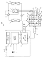
- FIG. 1 is a diagram showing a configuration of a heat pump device 100 according to Embodiment 1.
- FIG. The figure which shows eight kinds of switching patterns. 7 is a flowchart showing the operation of the inverter control unit 12. The timing chart at the time of switching voltage command value Vu *, Vv *, Vw * by turns at the timing of the top (peak) and the bottom (valley) of a carrier signal.
- FIG. 6 is an explanatory diagram of an output voltage and a current flowing through the motor 8 when the inverter 9 is operated by the PWM signal shown in FIG. 5.
- FIG. 6 is a timing chart different from FIG.
- FIG. 9 is an explanatory diagram of an output voltage and a current flowing through the motor 8 when the inverter 9 is operated by the PWM signal shown in FIG. 8.
- the figure which shows the structural example of the power supply part 30 of the inverter. 1 is a circuit configuration diagram of a heat pump device 100 according to Embodiment 1.
- FIG. 1 is a diagram illustrating a configuration of a heat pump device 100 according to the first embodiment.
- the heat pump device 100 includes a refrigeration cycle in which a compressor 1, a four-way valve 2, a heat exchanger 3, an expansion mechanism 4, and a heat exchanger 5 are sequentially connected by a refrigerant pipe 6. Inside the compressor 1, a compression mechanism 7 that compresses the refrigerant and a motor 8 that operates the compression mechanism 7 are provided. An inverter 9 that drives the motor 8 by applying a voltage is electrically connected to the motor 8.
- the DC power supply 10 of the inverter 9 is provided with a bus voltage detection unit 11 that detects a bus voltage that is the voltage.
- a control input terminal of the inverter 9 is connected to the inverter control unit 12.
- the inverter control unit 12 includes a heating determination unit 13, a voltage command generation unit 14 (voltage command selection unit), and a PWM signal generation unit 15 (drive signal generation unit).
- the inverter 9 is a three-phase inverter in which series connection circuits of two switching elements (16a and 16d, 16b and 16e, 16c and 16f) are connected in parallel for three phases.
- the inverter 9 is switched by PWM signals UP, VP, WP, UN, VN, WN (driving signals) sent from the inverter control unit 12 to correspond to the switching elements (UP is 16a, VP is 16b, WP is 16c, UN drives 16d, VN drives 16e, and WN drives 16f).
- the inverter control unit 12 determines the voltage applied to the motor 8 by the voltage command generation unit 14 when the heating determination unit 13 determines that the liquid refrigerant has accumulated in the compressor 1 (the refrigerant has stagnated). Command values Vu *, Vv *, and Vw *.
- the PWM signal generation unit 15 generates a PWM signal based on the voltage command values Vu *, Vv *, and Vw * obtained by the voltage command generation unit 14.
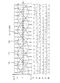
- FIG. 2 is a diagram illustrating input / output waveforms of the PWM signal generation unit 15.
- the voltage command values Vu *, Vv *, and Vw * are defined as sine waves whose phases are different by 2 ⁇ / 3 as shown in equations (1) to (3).
- ⁇ is the phase of the voltage command value (an example of an operation command)
- A is the amplitude of the voltage command value.
- Vu * Acos ⁇
- Vv * Acos ( ⁇ (2/3) ⁇ )
- Vw * Acos ( ⁇ + (2/3) ⁇ )
- the voltage command generation unit 14 calculates the voltage command values Vu *, Vv *, and Vw * by the equations (1) to (3), and calculates the calculated voltage command value Vu *.
- Vv *, Vw * are output to the PWM signal generator 15.
- the PWM signal generation unit 15 compares the voltage command values Vu *, Vv *, and Vw * with a carrier signal (reference signal) having a predetermined frequency and an amplitude Vdc / 2, and determines the PWM signal UP, VP, WP, UN, VN, WN are generated.
- Vdc is a bus voltage detected by the bus voltage detector 11. For example, when the voltage command value Vu * is larger than the carrier signal, UP outputs a voltage for turning on the switching element 16a, and UN outputs a voltage for turning off the switching element 16d.
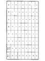
- FIG. 3 is a diagram illustrating eight switching patterns.
- reference symbols V0 to V7 are given to voltage vectors generated in each switching pattern.
- the voltage direction of each voltage vector is represented by ⁇ U, ⁇ V, ⁇ W (0 when no voltage is generated).
- + U is a voltage that generates a current in the U-phase direction that flows into the motor 8 via the U-phase and flows out of the motor 8 via the V-phase and the W-phase
- ⁇ U is the V-phase.
- a voltage that generates a current in the ⁇ U-phase direction that flows into the motor 8 via the W-phase and flows out of the motor 8 via the U-phase.
- ⁇ V and ⁇ W The same interpretation is applied to ⁇ V and ⁇ W.
- a desired voltage can be output to the inverter 9 by outputting a voltage vector by combining the switching patterns shown in FIG.
- the phase ⁇ is changed at high speed, and the frequency of the modulation wave (three sine waves in FIG. 2) that defines the voltage command values Vu *, Vv *, and Vw * is increased to output a high-frequency voltage. It becomes possible.
- the voltage vectors V0 and V7 where no voltage is generated are called zero vectors, and the other voltage vectors are called real vectors.
- the voltage command values Vu *, Vv *, Vw * may be obtained by two-phase modulation, third harmonic superposition modulation, space vector modulation, or the like.
- FIG. 4 is a flowchart showing the operation of the inverter control unit 12.
- S1 heating judgment step
- the heating determination unit 13 determines whether to operate the voltage command generation unit 14 based on whether or not the refrigerant has accumulated in the compressor 1 while the operation of the compressor 1 is stopped.
- the process proceeds to S2 and enters a heating operation mode in which a PWM signal for preheating is generated. Transition.
- the heating determination unit 13 determines that the voltage command generation unit 14 is not operated because the refrigerant is not retained in the compressor 1 (NO in S1)
- the voltage command generation unit 14 is operated again after a predetermined time has elapsed. Judge whether to make it.
- S2 Voltage command value generation step
- the voltage command generation unit 14 calculates the voltage command values Vu *, Vv *, and Vw * by the equations (1) to (3), and calculates the calculated voltage command value Vu *. , Vv *, Vw * are output to the PWM signal generator 15.
- the PWM signal generation unit 15 compares the voltage command values Vu *, Vv *, and Vw * output from the voltage command generation unit 14 with the carrier signal to obtain the PWM signals UP, VP, WP, UN, VN, and WN. And output to the inverter 9. As a result, the switching elements 17 a to 17 f of the inverter 9 are driven to apply a high frequency voltage to the motor 8.
- the motor 8 is efficiently heated by the iron loss of the motor 8 and the copper loss generated by the current flowing through the winding.
- the liquid refrigerant staying in the compressor 1 is heated and vaporized, and leaks to the outside of the compressor 1. After a predetermined time has elapsed, the process returns to S1 again to determine whether further heating is necessary.
- a high frequency voltage equal to or higher than the operation frequency during the compression operation (compression operation mode) is applied to the motor 8, the rotor in the motor 8 cannot follow the frequency, and rotation and vibration are not generated.
- the operating frequency during the compression operation is at most 1 kHz. Therefore, a high frequency voltage of 1 kHz or higher may be applied to the motor 8.
- a high frequency voltage of 14 kHz or higher is applied to the motor 8, the vibration sound of the iron core of the motor 8 approaches the upper limit of the audible frequency, which is effective in reducing noise.
- the upper limit of the carrier frequency which is the frequency of the carrier signal, is determined by the switching speed of the switching element of the inverter. For this reason, it is difficult to output a high-frequency voltage equal to or higher than the carrier frequency that is a carrier wave.
- the upper limit of the switching speed is about 20 kHz.
- the frequency of the modulation wave defining the voltage command values Vu *, Vv *, and Vw * is about 1/10 of the carrier frequency, the waveform output accuracy of the high-frequency voltage may be deteriorated and a DC component may be superimposed. There is.
- the carrier frequency is 20 kHz
- the frequency of the modulated wave is 2 kHz or less, which is 1/10 of the carrier frequency
- the frequency of the high frequency voltage becomes an audible frequency region, and there is a concern about noise deterioration.
- the voltage command generator 14 does not calculate the voltage command values Vu *, Vv *, and Vw * by the method described based on FIG. 2, but synchronizes with the carrier signal to generate the voltage command value Vu. *, Vv *, and Vw * are alternately switched between Hi (here, + A) and Lo (here, -A).
- FIG. 5 is a timing chart when the voltage command values Vu *, Vv *, and Vw * are alternately switched at the top (peak) and bottom (valley) timing of the carrier signal. In FIG.
- the voltage command value Vu * is Lo
- the voltage command values Vv * and Vw * are Hi
- the carrier signal is from the top to the bottom.
- the voltage command value Vu * is Hi
- the voltage command values Vv * and Vw * are Lo in the interval up to (hereinafter referred to as the latter half).
- UP and UN, VP and VN, and WP and WN are on / off states opposite to each other, and if one is known, the other is also known, so only UP, VP, and WP are shown here.
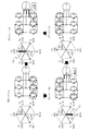
- FIG. 6 is an explanatory diagram of changes in the voltage vector shown in FIG.
- the switching element 16 surrounded by a broken line is turned on, and the switching element 16 not surrounded by a broken line is turned off.
- the lines of the motor 8 are short-circuited and no voltage is output.
- the energy stored in the inductance of the motor 8 becomes a current and flows in the short circuit. That is, a return current that circulates between the motor 8 and the inverter 9 flows by the diode 17 connected in reverse parallel to the switching elements 16a to 16f of the inverter 9.
- a current in the U-phase direction flows into the motor 8 via the U phase and flows out of the motor 8 via the V phase and the W phase.
- a current in the ⁇ U phase direction ( ⁇ Iu current) flowing into the motor 8 via the phase and the W phase and flowing out of the motor 8 via the U phase flows in the winding of the motor 8. That is, a current in the reverse direction flows through the winding of the motor 8 when the V4 vector is applied and when the V3 vector is applied. Since the voltage vector changes in the order of V0, V4, V7, V3, V0,..., + Iu current and ⁇ Iu current flow alternately in the winding of the motor 8. In particular, as shown in FIG.
- FIG. 7 is an explanatory diagram of the output voltage and the current flowing through the motor 8 when the inverter 9 is operated by the PWM signal shown in FIG.
- the current flowing through the motor 8 increases at the voltage vector V4 and decreases at the voltage vector V3.
- the voltage vectors V0 and V7 are zero vectors, as described above, the return current that circulates between the motor 8 and the inverter 9 by the diode 17 connected in reverse parallel to the switching elements 16a to 16f of the inverter 9. Flows.
- the refrigerant staying in the compressor can be efficiently heated by using a state in which the current of zero vector is returned to the motor 8 without turning off all the switching elements. .
- FIG. 8 is a timing chart different from FIG. 5 when the voltage command values Vu *, Vv *, and Vw * are alternately switched at the top and bottom timings of the carrier signal.
- the difference between FIG. 5 and FIG. 8 is that the relationship between the phase of the carrier frequency and the phase of the voltage command (Vu *, Vv *, Vw *) is reversed. That is, in FIG. 8, in the first half of the carrier signal, the voltage command value Vu * is Hi, the voltage command values Vv * and Vw * are Lo, and in the second half of the carrier signal, the voltage command value Vu * is Lo and the voltage command value Vv. *, Vw * is Hi. When the voltage command values Vu *, Vv *, and Vw * shown in FIG.
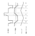
- FIG. 9 is an explanatory diagram of the output voltage and the current flowing through the motor 8 when the inverter 9 is operated by the PWM signal shown in FIG.
- the broken lines indicate the output voltage shown in FIG. 7 (that is, when the inverter 9 is operated with the PWM signal shown in FIG. 5) and the current flowing through the motor 8.
- the current is inverted at the voltage vectors V3 and V4 which are real vectors, and an alternating high-frequency current is generated.
- the rise of the output voltage is slower than in the case of the phase relationship shown in FIG. 5, and the output voltage becomes lower than the voltage command values Vu *, Vv *, and Vw *. Will occur.
- the polarity change of the current flowing through the motor 8 is delayed, and the amount of current flowing through the motor 8 is reduced as compared with the case where the inverter 9 is operated by the PWM signal shown in FIG. Therefore, when the inverter 9 is operated with the PWM signal shown in FIG. 8, the power for preheating the motor 8 is smaller than when the inverter 9 is operated with the PWM signal shown in FIG. 5, and the same voltage command value Vu. Regardless of *, Vv *, Vw *, the amount of preheating is reduced.
- the current change is only attenuation due to the impedance consumption of the motor 8, so the current time change rate di / dt indicating the magnitude of the current change per time is small.
- the current time change rate di / dt is large.
- the current time change rate di / dt may be small.
- the current time change rate di / dt is originally changed to a small state, and thus the influence is small.
- the change from the zero vector to the real vector is a case where the current-time change rate di / dt changes from a small state to a large state.
- the current time change rate di / dt is changed even though the current time change rate di / dt is changed to a large state. Because it becomes smaller, the impact is great.
- the polarity change of the motor 8 current is delayed due to the influence that the current cannot be changed greatly despite the fact that the current is changed to a state where the current is changed greatly. Therefore, if two-phase switching occurs when changing from a zero vector to a real vector, the polarity change of the current flowing through the motor 8 is delayed.
- the inductance component of the motor 8 is increased and the winding impedance is increased, so that the current flowing through the winding is reduced and the current flowing through the inverter 9 is also reduced.
- the current that flows in the motor 8 is split off to the two switching elements and is simultaneously turned off and is commutated to the diode 17 connected in antiparallel. Become.
- the current flowing through the inverter 9 is small, a tail is generated when the switching element 16 is turned off, and it takes time until the current becomes zero. Therefore, when two-phase switching occurs, the rise of the output voltage is delayed, and the polarity change of the current flowing through the motor 8 is delayed.
- the voltage command generator 14 does not generate a voltage command value that causes two-phase switching when changing from a zero vector to a real vector, but only when changing from a real vector to a zero vector.
- a voltage command value that generates switching is generated.
- the commutation of the current by switching on and off the switching element 16 can be performed smoothly.
- the delay in rising of the output voltage can be suppressed, an output voltage according to the voltage command value can be obtained, and the amount of preheating can be ensured.
- the inverter 9 is set with an upper and lower arm short-circuit prevention time generally called Td. During the Td period, all the switching elements are turned off and a reflux current flows.
- the heat pump device 100 retains in the compressor due to the iron loss of the motor and the copper loss generated by the current flowing through the winding by applying the high frequency voltage to the motor 8. It is possible to efficiently heat the refrigerant. In particular, the generation of a voltage command value that causes two-phase switching when changing from a zero vector to a real vector is prohibited, allowing current to flow efficiently to the motor, resulting in stagnation in the compressor. It is possible to efficiently heat the refrigerant. Further, since the high frequency voltage is applied to the motor 8, no rotational torque or vibration is generated.
- an IPM Interior Permanent Magnet
- a concentrated winding motor with a small coil end and a low winding resistance are widely used for high efficiency. Since the concentrated winding motor has a small winding resistance and a small amount of heat generated by copper loss, a large amount of current needs to flow through the winding. When a large amount of current is passed through the windings, the current flowing through the inverter 9 also increases and the inverter loss increases. Therefore, when heating is performed by applying the above-described high frequency voltage, an inductance component due to a high frequency is increased, and the winding impedance is increased.
- the current flowing through the winding is reduced and the copper loss is reduced, the iron loss due to the application of the high frequency voltage is generated and heating can be performed effectively. Furthermore, since the current flowing through the winding is reduced, the current flowing through the inverter is also reduced, the loss of the inverter 9 can be reduced, and more efficient heating is possible. Further, when heating is performed by applying the high-frequency voltage described above, when the compressor is an IPM motor, the rotor surface where the high-frequency magnetic flux is linked also becomes a heat generating portion. For this reason, an increase in the refrigerant contact surface and rapid heating of the compression mechanism are realized, so that the refrigerant can be efficiently heated.
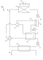
- FIG. 10 is a diagram illustrating a configuration example of the power supply unit 30 of the inverter 9.
- the power supply unit 30 is shown as the DC power supply 10.
- the power supply unit 30 smoothes the outputs of the three-phase four-wire AC power supply 31, the three-phase rectifier 32 (first rectifier) that rectifies the three-phase AC output of the AC power supply 31, the DCL 33, and the three-phase rectifier 32.
- a smoothing capacitor 34 an ACL 35, a single-phase rectifier 36 (second rectifier) that rectifies the output of any one phase and neutral point of the AC power supply 31, and a smoothing capacitor that smoothes the output of the single-phase rectifier 36. 37, and a switching unit 38 that switches whether the smoothing capacitor 34 or the smoothing capacitor 37 outputs the voltage to the inverter 9.
- the voltage across the smoothing capacitor 34 and the smoothing capacitor 37 is different.
- the voltage across the smoothing capacitor 37 is 1 / ⁇ 3 times the voltage across the smoothing capacitor 34.
- the inverter 9 is driven using the voltage across the smoothing capacitor 34.
- the heating operation mode when the inverter 9 is driven using the voltage across the smoothing capacitor 34, the current loss is reduced by the inductance component of the motor 8 due to the high frequency, and the conduction loss due to the current flowing can be reduced. It increases itself. Note that the switching loss depends on the input voltage of the inverter 9.
- the inverter 9 is driven not using the voltage across the smoothing capacitor 34 but using the voltage across the smoothing capacitor 37. That is, in the compression operation mode, the switching unit 38 is switched so that a voltage is output from the smoothing capacitor 34 to the inverter 9 and in the heating operation mode, a voltage is output from the smoothing capacitor 37 to the inverter 9. As described above, the voltage across the smoothing capacitor 37 is 1 / ⁇ 3 times the voltage across the smoothing capacitor 34. Therefore, the input voltage of the inverter 9 in the heating operation mode can be lowered than in the compression operation mode, and the switching loss can be reduced.
- the switching loss in the inverter 9 in the heating operation mode can be reduced, the efficiency of the inverter 9 can be improved, and the power consumption can be reduced.
- switching noise can be reduced due to the voltage drop, and noise countermeasures can be realized at low cost.
- the DC voltage in the heating operation mode may be lowered by the other method than the method described based on FIG.
- the switching elements 16a to 16f constituting the inverter 9 and the diodes 17a to 17f connected in parallel to the switching elements 16a to 16f generally use a semiconductor made of silicon (Si).
- a semiconductor made of silicon Si
- SiC silicon carbide
- GaN gallium nitride
- a switching element or a diode element formed of such a wide band gap semiconductor has a high withstand voltage and a high allowable current density. Therefore, the switching element and the diode element can be reduced in size, and by using these reduced switching element and diode element, the semiconductor module incorporating these elements can be reduced in size.
- the switching element and the diode element formed by such a wide band gap semiconductor have high heat resistance.
- the heat sink fins of the heat sink can be miniaturized and the water cooling part can be air cooled, so that the semiconductor module can be further miniaturized.
- switching elements and diode elements formed of such a wide band gap semiconductor have low power loss. For this reason, it is possible to increase the efficiency of the switching element and the diode element, and to increase the efficiency of the semiconductor module.
- both the switching elements 16a to 16f and the diodes 17a to 17f are formed of a wide band gap semiconductor, but either one of the elements may be formed of a wide band gap semiconductor.
- only the upper switching elements 16a to 16c or the lower switching elements 16d to 16f may be formed of a wide band gap semiconductor.
- the diode 17 connected in antiparallel with the switching elements 16a to 16f may be formed of a wide band gap semiconductor. This is because the reflux current flows only by the impedance of the motor 8. In particular, the effect is large when the voltage command value is low so that the time during which the return current flows is long.
- the fan motor for air cooling may be stopped when a high frequency voltage is applied in the heating operation mode.
- the power consumption at the time of operation stop (during operation standby) can be further reduced by the amount of fan motor drive. Thereby, further reduction in standby power can be realized.
- MOSFET Metal-Oxide-Semiconductor Field-Effect Transistor
- the compressor 1 can be efficiently heated, and the liquid refrigerant in the compressor 1 can be prevented from staying. Therefore, since liquid compression can be prevented, it is effective even when a scroll compressor is used as the compressor 1.
- the amplitude of the voltage command value may be adjusted in advance so as not to exceed 50 W, or the feedback control may be performed so that the flowing current or voltage is detected to be 50 W or less.
- the inverter control unit 12 includes a CPU (Central Processing Unit), a DSP (Digital Signal Processor), a microcomputer (microcomputer), an electronic circuit, and the like.
- CPU Central Processing Unit
- DSP Digital Signal Processor
- microcomputer microcomputer
- FIG. 1 shows the heat pump device 100 in which the compressor 1, the four-way valve 2, the heat exchanger 3, the expansion mechanism 4, and the heat exchanger 5 are sequentially connected by piping.
- the heat pump apparatus 100 having a more specific configuration will be described.
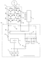
- FIG. 11 is a circuit configuration diagram of the heat pump device 100 according to the first embodiment.
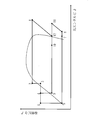
- FIG. 12 is a Mollier diagram of the state of the refrigerant in the heat pump apparatus 100 shown in FIG.
- the horizontal axis represents specific enthalpy and the vertical axis represents refrigerant pressure.
- a compressor 41, a heat exchanger 42, an expansion mechanism 43, a receiver 44, an internal heat exchanger 45, an expansion mechanism 46, and a heat exchanger 47 are sequentially connected by piping, Is provided with a main refrigerant circuit 48 that circulates.
- a four-way valve 49 is provided on the discharge side of the compressor 41 so that the refrigerant circulation direction can be switched.
- a fan 50 is provided in the vicinity of the heat exchanger 47.
- the compressor 41 is the compressor 1 described in the above embodiment, and includes the motor 8 driven by the inverter 9 and the compression mechanism 7.
- the heat pump apparatus 100 includes an injection circuit 52 that connects between the receiver 44 and the internal heat exchanger 45 to the injection pipe of the compressor 41 by piping.
- An expansion mechanism 51 and an internal heat exchanger 45 are sequentially connected to the injection circuit 52.
- a water circuit 53 through which water circulates is connected to the heat exchanger 42.
- the water circuit 53 is connected to a device that uses water, such as a water heater, a radiator or a radiator such as floor heating.
- the heating operation includes not only heating used for air conditioning, but also hot water supply that heats water to make hot water.
- the gas-phase refrigerant (point 1 in FIG. 12) that has become high-temperature and high-pressure in the compressor 41 is discharged from the compressor 41, and is heat-exchanged and liquefied by a heat exchanger 42 that is a condenser and a radiator (FIG. 12). Point 2). At this time, the water circulating through the water circuit 53 is warmed by the heat radiated from the refrigerant and used for heating and hot water supply. The liquid-phase refrigerant liquefied by the heat exchanger 42 is decompressed by the expansion mechanism 43 and becomes a gas-liquid two-phase state (point 3 in FIG. 12).
- the refrigerant in the gas-liquid two-phase state by the expansion mechanism 43 is heat-exchanged with the refrigerant sucked into the compressor 41 by the receiver 44, cooled, and liquefied (point 4 in FIG. 12).
- the liquid-phase refrigerant liquefied by the receiver 44 branches and flows into the main refrigerant circuit 48 and the injection circuit 52.
- the liquid-phase refrigerant flowing through the main refrigerant circuit 48 is heat-exchanged by the internal heat exchanger 45 with the refrigerant flowing through the injection circuit 52 that has been depressurized by the expansion mechanism 51 and is in a gas-liquid two-phase state, and further cooled (FIG. 12). Point 5).
- the liquid-phase refrigerant cooled by the internal heat exchanger 45 is decompressed by the expansion mechanism 46 and becomes a gas-liquid two-phase state (point 6 in FIG. 12).
- the refrigerant in the gas-liquid two-phase state by the expansion mechanism 46 is heat-exchanged with the outside air by the heat exchanger 47 serving as an evaporator and heated (point 7 in FIG. 12).
- the refrigerant heated by the heat exchanger 47 is further heated by the receiver 44 (point 8 in FIG. 12) and sucked into the compressor 41.
- the refrigerant flowing through the injection circuit 52 is decompressed by the expansion mechanism 51 (point 9 in FIG. 12) and heat-exchanged by the internal heat exchanger 45 (point 10 in FIG.
- the gas-liquid two-phase refrigerant (injection refrigerant) heat-exchanged by the internal heat exchanger 45 flows into the compressor 41 from the injection pipe of the compressor 41 in the gas-liquid two-phase state.
- the refrigerant sucked from the main refrigerant circuit 48 (point 8 in FIG. 12) is compressed and heated to an intermediate pressure (point 11 in FIG. 12).
- the injection refrigerant (point 10 in FIG. 12) joins the refrigerant compressed and heated to the intermediate pressure (point 11 in FIG. 12), and the temperature decreases (point 12 in FIG. 12).
- the opening of the expansion mechanism 51 is fully closed. That is, when the injection operation is performed, the opening degree of the expansion mechanism 51 is larger than the predetermined opening degree. However, when the injection operation is not performed, the opening degree of the expansion mechanism 51 is made larger than the predetermined opening degree. Make it smaller. Thereby, the refrigerant does not flow into the injection pipe of the compressor 41.
- the opening degree of the expansion mechanism 51 is controlled by electronic control by a control unit such as a microcomputer.
- the cooling operation includes not only cooling used for air conditioning but also making cold water by taking heat from water, freezing and the like.
- the gas-phase refrigerant (point 1 in FIG. 12) that has become high-temperature and high-pressure in the compressor 41 is discharged from the compressor 41, and is heat-exchanged and liquefied by a heat exchanger 47 that is a condenser and a radiator (FIG. 12).
- Point 2 The liquid phase refrigerant liquefied by the heat exchanger 47 is depressurized by the expansion mechanism 46 and becomes a gas-liquid two-phase state (point 3 in FIG. 12).
- the refrigerant in the gas-liquid two-phase state by the expansion mechanism 46 is heat-exchanged by the internal heat exchanger 45, cooled and liquefied (point 4 in FIG. 12).
- the refrigerant that has become a gas-liquid two-phase state by the expansion mechanism 46 and the liquid-phase refrigerant that has been liquefied by the internal heat exchanger 45 have been decompressed by the expansion mechanism 51, and have become a gas-liquid two-phase state.
- Heat is exchanged with the refrigerant (point 9 in FIG. 12).
- the liquid phase refrigerant (point 4 in FIG. 12) heat-exchanged by the internal heat exchanger 45 branches and flows to the main refrigerant circuit 48 and the injection circuit 52.
- the liquid-phase refrigerant flowing through the main refrigerant circuit 48 is heat-exchanged with the refrigerant sucked into the compressor 41 by the receiver 44 and further cooled (point 5 in FIG.
- the liquid-phase refrigerant cooled by the receiver 44 is decompressed by the expansion mechanism 43 and becomes a gas-liquid two-phase state (point 6 in FIG. 12).
- the refrigerant that has been in the gas-liquid two-phase state by the expansion mechanism 43 is heat-exchanged and heated by the heat exchanger 42 serving as an evaporator (point 7 in FIG. 12).
- the heat exchanger 42 serving as an evaporator
- the refrigerant absorbs heat the water circulating in the water circuit 53 is cooled and used for cooling and freezing.
- the refrigerant heated by the heat exchanger 42 is further heated by the receiver 44 (point 8 in FIG. 12) and sucked into the compressor 41.
- the refrigerant flowing through the injection circuit 52 is decompressed by the expansion mechanism 51 (point 9 in FIG. 12) and heat-exchanged by the internal heat exchanger 45 (point 10 in FIG. 12).
- the gas-liquid two-phase refrigerant (injection refrigerant) heat-exchanged by the internal heat exchanger 45 flows from the injection pipe of the compressor 41 in the gas-liquid two-phase state.
- the compression operation in the compressor 41 is the same as in the heating operation.
- the opening degree of the expansion mechanism 51 is fully closed so that the refrigerant does not flow into the injection pipe of the compressor 41 as in the heating operation.
- the heat exchanger 42 has been described as a heat exchanger such as a plate heat exchanger that exchanges heat between the refrigerant and the water circulating in the water circuit 53.
- the heat exchanger 42 is not limited to this, and may exchange heat between the refrigerant and the air.
- the water circuit 53 may be a circuit in which other fluid circulates instead of a circuit in which water circulates.
- the heat pump device 100 can be used for a heat pump device using an inverter compressor such as an air conditioner, a heat pump water heater, a refrigerator, or a refrigerator.
- an inverter compressor such as an air conditioner, a heat pump water heater, a refrigerator, or a refrigerator.
Landscapes
- Engineering & Computer Science (AREA)
- Power Engineering (AREA)
- Mechanical Engineering (AREA)
- General Engineering & Computer Science (AREA)
- Physics & Mathematics (AREA)
- Thermal Sciences (AREA)
- Inverter Devices (AREA)
- Control Of Ac Motors In General (AREA)
- Compression-Type Refrigeration Machines With Reversible Cycles (AREA)
Abstract
Description
特許文献1及び特許文献2では、外気温度の低下に応じて圧縮機に高周波の交流電圧を印加することにより、圧縮機を加熱もしくは保温し、圧縮機内部の潤滑作用を円滑にしている。
特許文献2には、25kHzといった高周波の単相交流電源を印加することが記載されている。高周波の単相交流電源であるため、特許文献2の図3に示されるように、全てのスイッチング素子がオフとなる全オフ区間が比較的長く発生することになる。全オフ区間では、高周波電流は還流ダイオードを介してモータへ還流せずに、直流電源に回生される。そのため、全オフ区間では、電流の減衰が早く、モータに効率的に高周波電流が流れないため、圧縮機の加熱効率が悪くなってしまう。
この発明は、圧縮機内に滞留した冷媒を効率よく加熱することを目的とする。
冷媒を圧縮する圧縮機構を有する圧縮機と、
前記圧縮機が有する前記圧縮機構を動作させるモータと、
前記モータに所定の電圧を印加するインバータであって、2つのスイッチング素子の直列接続部を3個並列に接続して構成された三相インバータと、
前記三相インバータの各スイッチング素子に対応する6つの駆動信号を生成し、生成した各駆動信号を前記三相インバータの対応するスイッチング素子へ出力することにより、前記三相インバータに高周波交流電圧を発生させるインバータ制御部であって、前記三相インバータの正電圧側又は負電圧側の3つのスイッチング素子の全てをオンの状態とするスイッチングパターンAの駆動信号を生成するとともに、前記スイッチングパターンAの駆動信号の次には、前記3つのスイッチング素子のうち2つ以上のスイッチング素子をオフの状態とするスイッチングパターンの駆動信号を生成することなく、前記3つのスイッチング素子のうち2つのスイッチング素子をオンの状態とし、1つのスイッチング素子をオフの状態とするスイッチングパターンBの駆動信号を生成するインバータ制御部と
を備えることを特徴とする。
特に、この発明に係るヒートポンプ装置では、正電圧側の3つのスイッチング素子の全てがオンの状態から、前記正電圧側の3つのスイッチング素子のうち2つ以上のスイッチング素子が同時にオフになることなく、1つのスイッチング素子がオフになる。そのため、モータに電流を効率的に流すことができ、結果として圧縮機内に滞留した冷媒を効率よく加熱することができる。
図1は、実施の形態1におけるヒートポンプ装置100の構成を示す図である。
ヒートポンプ装置100は、圧縮機1、四方弁2、熱交換器3、膨張機構4、熱交換器5が冷媒配管6によって順次接続された冷凍サイクルを備える。圧縮機1の内部には、冷媒を圧縮する圧縮機構7と、圧縮機構7を動作させるモータ8とが設けられている。
また、モータ8に電圧を与え駆動させるインバータ9は、モータ8と電気的に接続されている。インバータ9の直流電源10には、その電圧である母線電圧を検出する母線電圧検出部11が設けられている。インバータ9の制御入力端は、インバータ制御部12と接続されている。インバータ制御部12は、加熱判定部13、電圧指令生成部14(電圧指令選択部)、PWM信号生成部15(駆動信号生成部)を備える。
インバータ制御部12は、加熱判定部13が圧縮機1内に液冷媒が滞留した状態(冷媒が寝込んだ状態)であると判断した場合に、電圧指令生成部14にてモータ8に印加する電圧の指令値Vu*、Vv*、Vw*を求める。そして、電圧指令生成部14が求めた電圧指令値Vu*、Vv*、Vw*を元に、PWM信号生成部15にてPWM信号を生成する。
図2は、PWM信号生成部15の入出力波形を示す図である。
例えば、電圧指令値Vu*、Vv*、Vw*を式(1)~式(3)のように位相が2π/3づつ異なる正弦波と定義する。但し、θは電圧指令値の位相(運転指令の一例)、Aは電圧指令値の振幅である。
(1)Vu*=Acosθ
(2)Vv*=Acos(θ-(2/3)π)
(3)Vw*=Acos(θ+(2/3)π)
電圧指令生成部14は、電圧位相指令θと振幅Aとに基づき、式(1)~式(3)により電圧指令値Vu*、Vv*、Vw*を計算し、計算した電圧指令値Vu*、Vv*、Vw*をPWM信号生成部15へ出力する。PWM信号生成部15は、電圧指令値Vu*、Vv*、Vw*と、所定の周波数で振幅Vdc/2のキャリア信号(基準信号)とを比較し、相互の大小関係に基づきPWM信号UP、VP、WP、UN、VN、WNを生成する。なお、Vdcは、母線電圧検出部11にて検出される母線電圧である。
例えば、電圧指令値Vu*がキャリア信号よりも大きい場合には、UPはスイッチング素子16aをオンにする電圧を出力し、UNはスイッチング素子16dをオフにする電圧を出力する。また、電圧指令値Vu*がキャリア信号よりも小さい場合には、逆に、UPはスイッチング素子16aをオフにする電圧を出力し、UNはスイッチング素子16dをオンにする電圧を出力する。他の信号についても同様であり、電圧指令値Vv*とキャリア信号との比較によりVP、VNが決定され、電圧指令値Vw*とキャリア信号との比較によりWP、WNが決定される。
一般的なインバータの場合、相補PWM方式を採用しているため、UPとUN、VPとVN、WPとWNは互いに逆の関係となる。そのため、スイッチングパターンは全部で8通りとなり、8通りのスイッチングパターンを組み合わせることでインバータは電圧を出力する。
図3に示すスイッチングパターンを組み合わせて電圧ベクトルを出力することでインバータ9に所望の電圧を出力させることができる。このときに位相θを高速で変化させ、電圧指令値Vu*、Vv*、Vw*を定義する変調波(図2では3つの正弦波)の周波数を高くすることにより、高周波の電圧を出力することが可能となる。
なお、電圧が発生しない電圧ベクトルV0、V7をゼロベクトルと呼び、他の電圧ベクトルを実ベクトルと呼ぶ。
図4は、インバータ制御部12の動作を示すフローチャートである。
(S1:加熱判断ステップ)
加熱判定部13は、圧縮機1の運転停止中に、圧縮機1内に冷媒が滞留したか否かにより、電圧指令生成部14を動作させるかを判断する。
圧縮機1内に冷媒が滞留したため電圧指令生成部14を動作させると加熱判定部13が判断した場合(S1でYES)、処理をS2へ進め、予熱用のPWM信号を発生させる加熱運転モードへ移行する。一方、圧縮機1内に冷媒が滞留していないため電圧指令生成部14を動作させないと加熱判定部13が判断した場合(S1でNO)、所定時間経過後に、再び電圧指令生成部14を動作させるかを判断する。
(S2:電圧指令値生成ステップ)
電圧指令生成部14は、電圧位相指令θと振幅Aとに基づき、式(1)~式(3)により電圧指令値Vu*、Vv*、Vw*を計算し、計算した電圧指令値Vu*、Vv*、Vw*をPWM信号生成部15へ出力する。
(S3:PWM信号生成ステップ)
PWM信号生成部15は、電圧指令生成部14が出力した電圧指令値Vu*、Vv*、Vw*をキャリア信号と比較して、PWM信号UP、VP、WP、UN、VN、WNを得て、インバータ9へ出力する。これにより、インバータ9のスイッチング素子17a~17fを駆動してモータ8に高周波電圧を印加する。
モータ8に高周波電圧を印加することにより、モータ8の鉄損と、巻線に流れる電流にて発生する銅損とで効率よくモータ8が加熱される。モータ8が加熱されることにより、圧縮機1内に滞留する液冷媒が加熱されて気化し、圧縮機1の外部へと漏出する。
所定の時間経過後、再びS1へ戻りさらに加熱が必要かを判定する。
また、電圧指令値Vu*、Vv*、Vw*を定義する変調波の周波数がキャリア周波数の1/10程度になると、高周波電圧の波形出力精度が悪化し直流成分が重畳するなど悪影響を及ぼす虞がある。この点を考慮し、キャリア周波数を20kHzとした場合に、変調波の周波数をキャリア周波数の1/10の2kHz以下とすると、高周波電圧の周波数は可聴周波数領域となり、騒音悪化が懸念される。
図5は、キャリア信号の頂(山)及び底(谷)のタイミングで、電圧指令値Vu*、Vv*、Vw*を交互に切り替えた場合のタイミングチャートである。なお、図5では、キャリア信号の底から頂までの区間(以下、前半と呼ぶ)で、電圧指令値Vu*をLo、電圧指令値Vv*、Vw*をHiとし、キャリア信号の頂から底までの区間(以下、後半と呼ぶ)で、電圧指令値Vu*をHi、電圧指令値Vv*、Vw*をLoとしている。また、UPとUN、VPとVN、WPとWNはそれぞれオン/オフ状態が逆であり、一方がわかれば他方もわかるため、ここではUP、VP、WPのみを示している。
図5に示す電圧指令値Vu*、Vv*、Vw*をキャリア信号と比較すると、図5に示すようにPWM信号が変化する。そして、電圧ベクトルは、V0(UP=VP=WP=0)、V4(UP=1、VP=WP=0)、V7(UP=VP=WP=1)、V3(UP=0、VP=WP=1)、V0(UP=VP=WP=0)、・・・の順で変化する。
図6に示すように、V0ベクトル、V7ベクトル印加時はモータ8の線間が短絡状態となり、電圧が出力されない。この場合、モータ8のインダクタンスに蓄えられたエネルギーが電流となって短絡回路中を流れる。つまり、インバータ9のスイッチング素子16a~16fの逆並列に接続されたダイオード17により、モータ8とインバータ9とを循環する還流電流が流れる。また、V4ベクトル印加時には、U相を介してモータ8へ流入し、V相及びW相を介してモータ8から流出するU相方向の電流(+Iuの電流)が流れ、V3ベクトル印加時には、V相及びW相を介してモータ8へ流入し、U相を介してモータ8から流出する-U相方向の電流(-Iuの電流)がモータ8の巻線に流れる。つまり、V4ベクトル印加時と、V3ベクトル印加時とでは逆方向の電流がモータ8の巻線に流れる。そして、電圧ベクトルがV0、V4、V7、V3、V0、・・・の順で変化するため、+Iuの電流と-Iuの電流とが交互にモータ8の巻線に流れることになる。特に、図5に示すように、V4ベクトルとV3ベクトルとが1キャリア周期(1/fc)の間に現れるため、キャリア周波数fcに同期した交流電圧をモータ8の巻線に印加することが可能となる。
また、V4ベクトル(+Iuの電流)とV3ベクトル(-Iuの電流)とが交互に出力されるため、正逆のトルクが瞬時切り替わる。そのため、トルクが相殺されることによりロータの振動を抑えた電圧の印加が可能となる。
図7に示すように、モータ8に流れる電流は、電圧ベクトルV4の時に増加し、電圧ベクトルV3の時に減少する。また、ゼロベクトルである電圧ベクトルV0、V7の時は、上述したように、インバータ9のスイッチング素子16a~16fの逆並列に接続されたダイオード17により、モータ8とインバータ9とを循環する還流電流が流れる。
図8に示す電圧指令値Vu*、Vv*、Vw*をキャリア信号と比較すると、図8に示すようにPWM信号が変化する。そして、電圧ベクトルは、V0(UP=VP=WP=0)、V3(UP=0、VP=WP=1)、V7(UP=VP=WP=1)、V4(UP=1、VP=WP=0)、V0(UP=VP=WP=0)・・・の順で変化する。
つまり、図5では、図6に示す電圧ベクトルがV0から時計回りに変化していた。これに対して、図8では、図6に示す電圧ベクトルがV0から反時計回りに変化する。
図9に示すように、実ベクトルである電圧ベクトルV3、V4にて電流が反転して交流の高周波電流が生成される。しかし、図8に示す位相関係の場合は、図5に示す位相関係の場合に比べて、出力電圧の立ち上りが遅く、電圧指令値Vu*、Vv*、Vw*に対し出力電圧が低くなる現象が発生する。その結果、モータ8に流れる電流の極性変化が遅れ、モータ8に流れる電流量が、図5に示すPWM信号でインバータ9を動作させた場合と比較して少なくなる(破線参照)。
したがって、図8に示すPWM信号でインバータ9を動作させた場合、図5に示すPWM信号でインバータ9を動作させた場合に比べて、モータ8を予熱する電力が小さくなり、同じ電圧指令値Vu*、Vv*、Vw*にも拘らず予熱量が減少してしまう。
図8に示すPWM信号でインバータ9を動作させた場合、電圧ベクトルは、V0、V3、V7、V4、V0、・・・と順に変化する。この電圧ベクトルの軌跡においては、V0からV3へ変化する場合と、V7からV4へ変化する場合とにおいて、正電圧側又は負電圧側の2相分のスイッチング素子が同時に変化する2相スイッチングが発生している(図6参照)。つまり、ゼロベクトルから実ベクトルへ変化する場合において、2相スイッチングが発生している。
図5に示すPWM信号でインバータ9を動作させた場合でも2相スイッチングは発生している。しかし、図5に示すPWM信号でインバータ9を動作させた場合、電圧ベクトルは、V0、V4、V7、V3、V0、・・・と順に変化する。そのため、2相スイッチングが発生するのは、V4からV7へ変化する場合と、V3からV0へ変化する場合とである(図6参照)。つまり、実ベクトルからゼロベクトルへ変化する場合において、2相スイッチングが発生している。
2相スイッチングが発生した場合、スイッチング素子16を構成するアームが2つ同時に変化する。例えば、V0からV3へ変化する場合、VP=WP=0がVP=WP=1に変化する。すなわち、スイッチング素子16e、16fがオンからオフになり、スイッチング素子16b、16cがオフからオンなる。
ここで、2相スイッチングが発生すると電流時間変化率di/dtが小さくなる場合がある。
実ベクトルからゼロベクトルに変化する場合、電流時間変化率di/dtが大きい状態から小さい状態に変化する。この場合、2相スイッチングが発生して電流時間変化率di/dtが小さくなったとしても、もともと電流時間変化率di/dtが小さい状態に変化する場合であるため、影響は少ない。しかし、ゼロベクトルから実ベクトルに変化する場合は、電流時間変化率di/dtが小さい状態から大きい状態に変化する場合である。この場合、2相スイッチングが発生して電流時間変化率di/dtが小さくなると、電流時間変化率di/dtを大きい状態に変化させようとしているにも関わらず、電流時間変化率di/dtが小さくなってしまうため、影響が大きい。つまり、電流を大きく変化させる状態に変化させようとしているにも関わらず、電流を大きく変化させることができなくなってしまうこの影響により、モータ8電流の極性変化が遅れる。
そのため、ゼロベクトルから実ベクトルに変化する場合に2相スイッチングが発生すると、モータ8に流れる電流の極性変化が遅れてしまう。
これにより、スイッチング素子16のオンオフ切替えによる電流の転流をスムーズに行うことができる。その結果、出力電圧の立ち上りの遅れが抑制でき、電圧指令値通りの出力電圧が得られ、予熱量を確保できる。
なお、インバータ9には一般的にTdと呼ばれる上下アーム短絡防止時間が設定されている。Td期間中は、スイッチング素子全てがオフとなり、還流電流が流れる。そのため、Td期間中は、ゼロベクトル時より電流減衰が早く、図9に基づき説明した出力電圧歪みが発生し易い。したがって、Tdを有するインバータを用いた場合、ゼロベクトルから実ベクトルに変化する場合に、2相スイッチングが発生するような電圧指令値を生成しないことによる効果が顕著に現れる。
また、高周波電圧をモータ8に印加しているため、回転トルクや振動が発生することがない。
そこで、上述した高周波電圧印加による加熱を行うと、高周波数によるインダクタンス成分が大きくなり、巻線インピーダンスが高くなる。そのため、巻線に流れる電流が小さくなり銅損は減るものの、その分高周波電圧印加による鉄損が発生し効果的に加熱することができる。さらに、巻線に流れる電流が小さくなるため、インバータに流れる電流も小さくなり、インバータ9の損失も低減でき、より効率の高い加熱が可能となる。
また、上述した高周波電圧印加による加熱を行うと、圧縮機がIPM構造のモータである場合、高周波磁束が鎖交するロータ表面も発熱部となる。そのため、冷媒接触面増加や圧縮機構への速やかな加熱が実現されるため効率の良い冷媒の加熱が可能となる。
図10は、インバータ9の電源部30の構成例を示す図である。なお、図1では、電源部30を直流電源10として示していた。
電源部30は、三相四線式の交流電源31と、交流電源31の三相交流出力を整流する三相整流器32(第1整流器)と、DCL33と、三相整流器32の出力を平滑する平滑コンデンサ34と、ACL35と、交流電源31のいずれか一相と中性点との出力を入力として整流する単相整流器36(第2整流器)と、単相整流器36の出力を平滑する平滑コンデンサ37と、平滑コンデンサ34と平滑コンデンサ37とのいずれからインバータ9へ電圧を出力するかを切り替える切替部38とを備える。
圧縮運転モードでは、平滑コンデンサ34の両端電圧を用いてインバータ9を駆動する。しかし、加熱運転モードでは、平滑コンデンサ34の両端電圧を用いてインバータ9を駆動すると、高周波化によりモータ8のインダクタンス成分によって電流が低減して電流が流れることによる導通損失は低減できるが、スイッチング損失自体は増加してしまう。なお、スイッチング損失はインバータ9の入力電圧に依存する。
そこで、加熱運転モードでは、平滑コンデンサ34の両端電圧ではなく、平滑コンデンサ37の両端電圧を用いてインバータ9を駆動する。つまり、圧縮運転モードにおいては、平滑コンデンサ34からインバータ9へ電圧を出力し、加熱運転モードにおいては、平滑コンデンサ37からインバータ9へ電圧を出力するように切替部38を切り替える。上述したように、平滑コンデンサ37の両端電圧は、平滑コンデンサ34の両端電圧の1/√3倍である。したがって、圧縮運転モード時よりも、加熱運転モード時におけるインバータ9の入力電圧を低下させることができ、スイッチング損失を低減することができる。
このようなワイドバンドギャップ半導体によって形成されたスイッチング素子やダイオード素子は、耐電圧性が高く、許容電流密度も高い。そのため、スイッチング素子やダイオード素子の小型化が可能であり、これら小型化されたスイッチング素子やダイオード素子を用いることにより、これらの素子を組み込んだ半導体モジュールの小型化が可能となる。
また、このようなワイドバンドギャップ半導体によって形成されたスイッチング素子やダイオード素子は、耐熱性も高い。そのため、ヒートシンクの放熱フィンの小型化や、水冷部の空冷化が可能であるので、半導体モジュールの一層の小型化が可能になる。
さらに、このようなワイドバンドギャップ半導体によって形成されたスイッチング素子やダイオード素子は、電力損失が低い。そのため、スイッチング素子やダイオード素子の高効率化が可能であり、延いては半導体モジュールの高効率化が可能になる。
また、上側スイッチング素子16a~16cもしくは下側スイッチング素子16d~16fだけをワイドバンドギャップ半導体で構成してもよい。この場合、ゼロベクトルとなる電圧ベクトルをワイドバンドギャップ半導体で構成した側に合わせて配置することにより、電流が流れることにより発生する通流損失を低減することができる。
また、スイッチング素子16a~16fと逆並列に接続されているダイオード17のみワイドバンドギャップ半導体で構成してもよい。これは、還流電流がモータ8のインピーダンスだけで流れるためである。特に、還流電流が流れる時間が長くなるような電圧指令値の低い場合に効果が大きい。
なお、例えば、図1では、圧縮機1と、四方弁2と、熱交換器3と、膨張機構4と、熱交換器5とが配管により順次接続されたヒートポンプ装置100について示した。ここでは、より具体的な構成のヒートポンプ装置100について説明する。
図12は、図11に示すヒートポンプ装置100の冷媒の状態についてのモリエル線図である。図12において、横軸は比エンタルピ、縦軸は冷媒圧力を示す。
ヒートポンプ装置100は、圧縮機41と、熱交換器42と、膨張機構43と、レシーバ44と、内部熱交換器45と、膨張機構46と、熱交換器47とが配管により順次接続され、冷媒が循環する主冷媒回路48を備える。なお、主冷媒回路48において、圧縮機41の吐出側には、四方弁49が設けられ、冷媒の循環方向が切り替え可能となっている。また、熱交換器47の近傍には、ファン50が設けられる。また、圧縮機41は、上記実施の形態で説明した圧縮機1であり、インバータ9によって駆動されるモータ8と圧縮機構7とを有する圧縮機である。
さらに、ヒートポンプ装置100は、レシーバ44と内部熱交換器45との間から、圧縮機41のインジェクションパイプまでを配管により繋ぐインジェクション回路52を備える。インジェクション回路52には、膨張機構51、内部熱交換器45が順次接続される。
熱交換器42には、水が循環する水回路53が接続される。なお、水回路53には、給湯器、ラジエータや床暖房等の放熱器等の水を利用する装置が接続される。
熱交換器42で液化された液相冷媒は、膨張機構43で減圧され、気液二相状態になる(図12の点3)。膨張機構43で気液二相状態になった冷媒は、レシーバ44で圧縮機41へ吸入される冷媒と熱交換され、冷却されて液化される(図12の点4)。レシーバ44で液化された液相冷媒は、主冷媒回路48と、インジェクション回路52とに分岐して流れる。
主冷媒回路48を流れる液相冷媒は、膨張機構51で減圧され気液二相状態となったインジェクション回路52を流れる冷媒と内部熱交換器45で熱交換されて、さらに冷却される(図12の点5)。内部熱交換器45で冷却された液相冷媒は、膨張機構46で減圧されて気液二相状態になる(図12の点6)。膨張機構46で気液二相状態になった冷媒は、蒸発器となる熱交換器47で外気と熱交換され、加熱される(図12の点7)。そして、熱交換器47で加熱された冷媒は、レシーバ44でさらに加熱され(図12の点8)、圧縮機41に吸入される。
一方、インジェクション回路52を流れる冷媒は、上述したように、膨張機構51で減圧されて(図12の点9)、内部熱交換器45で熱交換される(図12の点10)。内部熱交換器45で熱交換された気液二相状態の冷媒(インジェクション冷媒)は、気液二相状態のまま圧縮機41のインジェクションパイプから圧縮機41内へ流入する。
圧縮機41では、主冷媒回路48から吸入された冷媒(図12の点8)が、中間圧まで圧縮、加熱される(図12の点11)。中間圧まで圧縮、加熱された冷媒(図12の点11)に、インジェクション冷媒(図12の点10)が合流して、温度が低下する(図12の点12)。そして、温度が低下した冷媒(図12の点12)が、さらに圧縮、加熱され高温高圧となり、吐出される(図12の点1)。
ここで、膨張機構51の開度は、マイクロコンピュータ等の制御部により電子制御により制御される。
主冷媒回路48を流れる液相冷媒は、レシーバ44で圧縮機41に吸入される冷媒と熱交換されて、さらに冷却される(図12の点5)。レシーバ44で冷却された液相冷媒は、膨張機構43で減圧されて気液二相状態になる(図12の点6)。膨張機構43で気液二相状態になった冷媒は、蒸発器となる熱交換器42で熱交換され、加熱される(図12の点7)。このとき、冷媒が吸熱することにより、水回路53を循環する水が冷やされ、冷房や冷凍に利用される。
そして、熱交換器42で加熱された冷媒は、レシーバ44でさらに加熱され(図12の点8)、圧縮機41に吸入される。
一方、インジェクション回路52を流れる冷媒は、上述したように、膨張機構51で減圧されて(図12の点9)、内部熱交換器45で熱交換される(図12の点10)。内部熱交換器45で熱交換された気液二相状態の冷媒(インジェクション冷媒)は、気液二相状態のまま圧縮機41のインジェクションパイプから流入する。
圧縮機41内での圧縮動作については、暖房運転時と同様である。
また、水回路53は、水が循環する回路ではなく、他の流体が循環する回路であってもよい。
Claims (11)
- 冷媒を圧縮する圧縮機構を有する圧縮機と、
前記圧縮機が有する前記圧縮機構を動作させるモータと、
前記モータに所定の電圧を印加するインバータであって、2つのスイッチング素子の直列接続部を3個並列に接続して構成された三相インバータと、
前記三相インバータの各スイッチング素子に対応する6つの駆動信号を生成し、生成した各駆動信号を前記三相インバータの対応するスイッチング素子へ出力することにより、前記三相インバータに高周波交流電圧を発生させるインバータ制御部であって、前記三相インバータの正電圧側又は負電圧側の3つのスイッチング素子の全てをオンの状態とするスイッチングパターンAの駆動信号を生成するとともに、前記スイッチングパターンAの駆動信号の次には、前記3つのスイッチング素子のうち2つ以上のスイッチング素子をオフの状態とするスイッチングパターンの駆動信号を生成することなく、前記3つのスイッチング素子のうち2つのスイッチング素子をオンの状態とし、1つのスイッチング素子をオフの状態とするスイッチングパターンBの駆動信号を生成するインバータ制御部と
を備えることを特徴とするヒートポンプ装置。 - 前記インバータ制御部は、
所定の周波数の基準信号に同期して、3つの電圧指令値Vu*,Vv*,Vw*それぞれを予め設定された2つの値に順に切り替えて選択する電圧指令選択部と、
前記電圧指令選択部が選択した3つの電圧指令値と前記基準信号とを比較して、前記三相インバータの各スイッチング素子に対応する6つの駆動信号を生成する駆動信号生成部と
を備えることを特徴とする請求項1に記載のヒートポンプ装置。 - 前記基準信号は、時間に対する値の変化における頂と谷とが特定可能な信号であり、
前記電圧指令選択部は、前記基準信号の頂と底との両方のタイミングで前記3つの電圧指令値Vu*,Vv*,Vw*それぞれを切り替える
ことを特徴とする請求項2に記載のヒートポンプ装置。 - 前記インバータ制御部は、前記圧縮機に冷媒を圧縮させる圧縮運転モードと、前記圧縮機を加熱する加熱運転モードとのいずれかで運転し、前記圧縮運転モードで運転する場合には、前記モータが回転する周波数の交流電圧を前記三相インバータに発生させ、前記加熱運転モードで運転する場合には、前記圧縮運転モードの場合に発生させる交流電圧の周波数より高く、前記モータが回転しない周波数の前記高周波交流電圧を前記三相インバータに発生させる
ことを特徴とする請求項1に記載のヒートポンプ装置。 - 前記ヒートポンプ装置は、さらに、
前記三相インバータへ電圧を印加する電源部であって、前記インバータ制御部が前記加熱運転モードで運転する場合には、前記インバータ制御部が前記圧縮運転モードで運転する場合よりも低い電圧を前記三相インバータへ印加する電源部
を備えることを特徴とする請求項4に記載のヒートポンプ装置。 - 前記電源部は、
三相四線式の交流電源と、
前記交流電源の三相交流出力を入力として整流する第1整流器と、
前記交流電源のいずれか一相と中性点との出力を入力として整流する第2整流器と、
前記インバータ制御部が前記圧縮運転モードで運転する場合には、前記第1整流器で整流された電圧を前記三相インバータへ印加し、前記インバータ制御部が前記加熱運転モードで運転する場合には、前記第2整流器で整流された電圧を前記三相インバータへ印加するように切り替える切替部と
を備えることを特徴とする請求項5に記載のヒートポンプ装置。 - 前記三相インバータを構成するスイッチング素子は、ワイドギャップ半導体である
ことを特徴とする請求項1に記載のヒートポンプ装置。 - 前記ワイドギャップ半導体は、SiC、GaN、ダイヤモンドのいずれかである
ことを特徴とする請求項7に記載のヒートポンプ装置。 - 前記三相インバータを構成するスイッチング素子は、スーパージャンクション構造のMOSFETである
ことを特徴とする請求項1に記載のヒートポンプ装置。 - 冷媒を圧縮する圧縮機構を有する圧縮機と、第1熱交換器と、膨張機構と、第2熱交換器とが配管により順次接続された冷媒回路を備えるヒートポンプ装置と、前記冷媒回路に接続された前記第1熱交換器で冷媒と熱交換された流体を利用する流体利用装置とを備えるヒートポンプシステムであり、
前記ヒートポンプ装置は、さらに、
前記圧縮機が有する前記圧縮機構を動作させるモータと、
前記モータに所定の電圧を印加するインバータであって、2つのスイッチング素子の直列接続部を3個並列に接続して構成された三相インバータと、
前記三相インバータの各スイッチング素子に対応する6つの駆動信号を生成し、生成した各駆動信号を前記三相インバータの対応するスイッチング素子へ出力することにより、前記三相インバータに高周波交流電圧を発生させるインバータ制御部であって、前記三相インバータの正電圧側又は負電圧側の3つのスイッチング素子の全てをオンの状態とするスイッチングパターンAの駆動信号を生成するとともに、前記スイッチングパターンAの駆動信号の次には、前記3つのスイッチング素子のうち2つ以上のスイッチング素子をオフの状態とするスイッチングパターンの駆動信号を生成することなく、前記3つのスイッチング素子のうち2つのスイッチング素子をオンの状態とし、1つのスイッチング素子をオフの状態とするスイッチングパターンBの駆動信号を生成するインバータ制御部と
を備えることを特徴とするヒートポンプシステム。 - 冷媒を圧縮する圧縮機構を有する圧縮機と、
前記圧縮機が有する前記圧縮機構を動作させるモータと、
前記モータに所定の電圧を印加するインバータであって、2つのスイッチング素子の直列接続部を3個並列に接続して構成された三相インバータと
を備えるヒートポンプ装置における前記三相インバータの制御方法であり、
前記三相インバータの各スイッチング素子に対応する6つの駆動信号を生成し、生成した各駆動信号を前記三相インバータの対応するスイッチング素子へ出力することにより、前記三相インバータに高周波交流電圧を発生させるインバータ制御工程であって、前記三相インバータの正電圧側又は負電圧側の3つのスイッチング素子の全てをオンの状態とするスイッチングパターンAの駆動信号を生成するとともに、前記スイッチングパターンAの駆動信号の次には、前記3つのスイッチング素子のうち2つ以上のスイッチング素子をオフの状態とするスイッチングパターンの駆動信号を生成することなく、前記3つのスイッチング素子のうち2つのスイッチング素子をオンの状態とし、1つのスイッチング素子をオフの状態とするスイッチングパターンBの駆動信号を生成するインバータ制御工程
を備えることを特徴とする三相インバータの制御方法。
Priority Applications (7)
| Application Number | Priority Date | Filing Date | Title |
|---|---|---|---|
| US13/982,294 US9077274B2 (en) | 2011-02-07 | 2011-02-07 | Heat pump device, heat pump system, and method for controlling three-phase inverter |
| ES11858110T ES2743164T3 (es) | 2011-02-07 | 2011-02-07 | Dispositivo de bomba de calor, sistema de bomba de calor y método de control para inversor trifásico en un dispositivo de bomba de calor |
| JP2012556671A JP5693617B2 (ja) | 2011-02-07 | 2011-02-07 | ヒートポンプ装置、ヒートポンプシステム及び三相インバータの制御方法 |
| AU2011358803A AU2011358803B2 (en) | 2011-02-07 | 2011-02-07 | Heat pump device, heat pump system, and control method for three-phase inverter |
| PCT/JP2011/052480 WO2012107987A1 (ja) | 2011-02-07 | 2011-02-07 | ヒートポンプ装置、ヒートポンプシステム及び三相インバータの制御方法 |
| EP11858110.7A EP2674694B1 (en) | 2011-02-07 | 2011-02-07 | Heat pump device, heat pump system, and control method for three-phase inverter in a heat pump device |
| CN201180066932.0A CN103403473B (zh) | 2011-02-07 | 2011-02-07 | 热泵装置、热泵系统和三相逆变器的控制方法 |
Applications Claiming Priority (1)
| Application Number | Priority Date | Filing Date | Title |
|---|---|---|---|
| PCT/JP2011/052480 WO2012107987A1 (ja) | 2011-02-07 | 2011-02-07 | ヒートポンプ装置、ヒートポンプシステム及び三相インバータの制御方法 |
Publications (1)
| Publication Number | Publication Date |
|---|---|
| WO2012107987A1 true WO2012107987A1 (ja) | 2012-08-16 |
Family
ID=46638230
Family Applications (1)
| Application Number | Title | Priority Date | Filing Date |
|---|---|---|---|
| PCT/JP2011/052480 Ceased WO2012107987A1 (ja) | 2011-02-07 | 2011-02-07 | ヒートポンプ装置、ヒートポンプシステム及び三相インバータの制御方法 |
Country Status (7)
| Country | Link |
|---|---|
| US (1) | US9077274B2 (ja) |
| EP (1) | EP2674694B1 (ja) |
| JP (1) | JP5693617B2 (ja) |
| CN (1) | CN103403473B (ja) |
| AU (1) | AU2011358803B2 (ja) |
| ES (1) | ES2743164T3 (ja) |
| WO (1) | WO2012107987A1 (ja) |
Cited By (7)
| Publication number | Priority date | Publication date | Assignee | Title |
|---|---|---|---|---|
| WO2014038235A1 (ja) * | 2012-09-10 | 2014-03-13 | 三菱電機株式会社 | モータ駆動回路、およびそれを内蔵した駆動回路内蔵モータならびに駆動回路内蔵ポンプモータ、およびそれらを搭載した空気調和機、換気扇、ヒートポンプ給湯機、ならびに内蔵冷温水循環式空調機 |
| WO2014151375A1 (en) * | 2013-03-15 | 2014-09-25 | Trane International Inc. | Apparatuses, systems, and methods of variable frequency drive operation and control |
| WO2016046993A1 (ja) * | 2014-09-26 | 2016-03-31 | 三菱電機株式会社 | ヒートポンプ装置ならびに、それを備えた空気調和機、ヒートポンプ給湯機、冷蔵庫、および冷凍機 |
| WO2016071965A1 (ja) * | 2014-11-04 | 2016-05-12 | 三菱電機株式会社 | ヒートポンプ装置ならびに、それを備えた空気調和機、ヒートポンプ給湯機および冷凍機 |
| WO2016170585A1 (ja) * | 2015-04-20 | 2016-10-27 | 日産自動車株式会社 | 制御装置及び制御方法 |
| JP2016537953A (ja) * | 2013-11-19 | 2016-12-01 | ボンバルディアー プリモーフ ゲゼルシャフト ミット ベシュレンクテル ハフツングBombardier Primove GmbH | 三相1次巻線構造体を動作させる方法及び1次ユニット |
| JPWO2021144869A1 (ja) * | 2020-01-15 | 2021-07-22 |
Families Citing this family (19)
| Publication number | Priority date | Publication date | Assignee | Title |
|---|---|---|---|---|
| CN103270376B (zh) * | 2010-12-21 | 2015-04-15 | 三菱电机株式会社 | 热泵装置、热泵系统和三相逆变器的控制方法 |
| WO2012172684A1 (ja) * | 2011-06-17 | 2012-12-20 | 三菱電機株式会社 | ヒートポンプ装置、空気調和機および冷凍機 |
| AT515243A1 (de) * | 2013-12-19 | 2015-07-15 | Schneider Electric Power Drives Gmbh | Verfahren zur Ansteuerung parallel geschalteter Inverter |
| WO2016071963A1 (ja) * | 2014-11-04 | 2016-05-12 | 三菱電機株式会社 | 電動機駆動装置および空気調和機 |
| WO2016166802A1 (ja) * | 2015-04-13 | 2016-10-20 | 三菱電機株式会社 | 電動駆動装置及び冷凍サイクル装置 |
| JP6545527B2 (ja) * | 2015-05-19 | 2019-07-17 | サンデン・オートモーティブコンポーネント株式会社 | 電動圧縮機 |
| KR101629397B1 (ko) * | 2015-12-03 | 2016-06-13 | 연세대학교 산학협력단 | 비대칭 모듈러 멀티레벨 컨버터 제어 장치 및 방법 |
| US10582962B2 (en) | 2016-01-23 | 2020-03-10 | Covidien Lp | System and method for harmonic control of dual-output generators |
| CN107204730A (zh) * | 2016-03-18 | 2017-09-26 | 日立江森自控空调有限公司 | 电动机控制装置、空调机、压缩机以及制冷循环装置 |
| US10869712B2 (en) * | 2016-05-02 | 2020-12-22 | Covidien Lp | System and method for high frequency leakage reduction through selective harmonic elimination in electrosurgical generators |
| US10637293B2 (en) * | 2016-09-30 | 2020-04-28 | University Of Tennessee Research Foundation | Dual-frequency mode transmitter for wireless power transfer |
| TW201826689A (zh) | 2016-10-05 | 2018-07-16 | 美商江森自控科技公司 | 用於暖氣、通風、空調及冷凍系統之變速驅動器 |
| CN110463027B (zh) | 2017-03-28 | 2020-11-20 | 大金工业株式会社 | 脉冲宽度调制方法 |
| US11498147B2 (en) * | 2018-05-01 | 2022-11-15 | Illinois Tool Works Inc. | Single phase input detection and power source protection |
| HRP20211716T1 (hr) | 2018-10-12 | 2022-02-18 | Dallan S.P.A. | Uređaj namijenjen rezanju komada iz lamelarnog materijala laserom ili plazmom |
| CN113785164A (zh) * | 2019-05-07 | 2021-12-10 | 三菱电机株式会社 | 热泵装置、热泵系统、空调机以及制冷机 |
| US12015362B2 (en) * | 2019-05-28 | 2024-06-18 | Mitsubishi Electric Corporation | Heat pump apparatus, air conditioner, and refrigerator |
| JP7306286B2 (ja) * | 2020-02-04 | 2023-07-11 | 株式会社デンソー | モータ制御装置 |
| GB2602338B (en) * | 2020-12-23 | 2023-03-15 | Yasa Ltd | A Method and Apparatus for Cooling One or More Power Devices |
Citations (6)
| Publication number | Priority date | Publication date | Assignee | Title |
|---|---|---|---|---|
| JPS6068341U (ja) | 1983-10-19 | 1985-05-15 | 株式会社東芝 | ヒ−トポンプ式空気調和機 |
| JPS6191445A (ja) | 1984-10-12 | 1986-05-09 | Matsushita Electric Ind Co Ltd | 空気調和機の圧縮機駆動装置 |
| JP2003199389A (ja) * | 2001-12-27 | 2003-07-11 | Hitachi Ltd | モータの制御装置及びその制御方法 |
| JP2008057425A (ja) * | 2006-08-31 | 2008-03-13 | Daikin Ind Ltd | 流体機械及びヒートポンプ装置 |
| JP2010074898A (ja) * | 2008-09-17 | 2010-04-02 | Renesas Technology Corp | 同期電動機の駆動システム |
| WO2010119526A1 (ja) * | 2009-04-15 | 2010-10-21 | 三菱電機株式会社 | インバータ装置、電動機駆動装置、冷凍空調装置、及び発電システム |
Family Cites Families (11)
| Publication number | Priority date | Publication date | Assignee | Title |
|---|---|---|---|---|
| JPH06185835A (ja) * | 1992-12-18 | 1994-07-08 | Toshiba Corp | インバータ装置およびそのインバータ装置により制御されるエアコンディショナ |
| JPH08226714A (ja) | 1995-02-23 | 1996-09-03 | Matsushita Electric Ind Co Ltd | 空気調和機 |
| JPH11159467A (ja) | 1997-11-28 | 1999-06-15 | Zexel:Kk | 電動機予熱装置における通電制御方法及び電動機予熱装置 |
| JP2000112547A (ja) * | 1998-10-05 | 2000-04-21 | Mitsubishi Electric Corp | 基板電圧発生回路および半導体集積回路装置 |
| ES2300538T3 (es) * | 2002-12-12 | 2008-06-16 | Matsushita Electric Industrial Co., Ltd | Aparato de control de motor. |
| EP1501186B1 (en) * | 2003-07-18 | 2018-08-22 | III Holdings 10, LLC | Motor driving apparatus |
| JP4895703B2 (ja) * | 2006-06-28 | 2012-03-14 | 三洋電機株式会社 | モータ制御装置 |
| KR101561922B1 (ko) * | 2007-12-21 | 2015-10-20 | 엘지전자 주식회사 | 공기조화기의 전동기 제어방법 |
| JP4390010B1 (ja) * | 2008-07-01 | 2009-12-24 | ダイキン工業株式会社 | 直接形変換装置及びその制御方法 |
| JP4471027B2 (ja) * | 2008-08-21 | 2010-06-02 | ダイキン工業株式会社 | 直接形変換装置及びその制御方法並びに制御信号生成装置 |
| JP5375715B2 (ja) * | 2010-03-31 | 2013-12-25 | 株式会社豊田自動織機 | 中性点昇圧方式の直流−三相変換装置 |
-
2011
- 2011-02-07 US US13/982,294 patent/US9077274B2/en active Active
- 2011-02-07 JP JP2012556671A patent/JP5693617B2/ja active Active
- 2011-02-07 CN CN201180066932.0A patent/CN103403473B/zh active Active
- 2011-02-07 ES ES11858110T patent/ES2743164T3/es active Active
- 2011-02-07 AU AU2011358803A patent/AU2011358803B2/en not_active Ceased
- 2011-02-07 WO PCT/JP2011/052480 patent/WO2012107987A1/ja not_active Ceased
- 2011-02-07 EP EP11858110.7A patent/EP2674694B1/en active Active
Patent Citations (6)
| Publication number | Priority date | Publication date | Assignee | Title |
|---|---|---|---|---|
| JPS6068341U (ja) | 1983-10-19 | 1985-05-15 | 株式会社東芝 | ヒ−トポンプ式空気調和機 |
| JPS6191445A (ja) | 1984-10-12 | 1986-05-09 | Matsushita Electric Ind Co Ltd | 空気調和機の圧縮機駆動装置 |
| JP2003199389A (ja) * | 2001-12-27 | 2003-07-11 | Hitachi Ltd | モータの制御装置及びその制御方法 |
| JP2008057425A (ja) * | 2006-08-31 | 2008-03-13 | Daikin Ind Ltd | 流体機械及びヒートポンプ装置 |
| JP2010074898A (ja) * | 2008-09-17 | 2010-04-02 | Renesas Technology Corp | 同期電動機の駆動システム |
| WO2010119526A1 (ja) * | 2009-04-15 | 2010-10-21 | 三菱電機株式会社 | インバータ装置、電動機駆動装置、冷凍空調装置、及び発電システム |
Non-Patent Citations (1)
| Title |
|---|
| See also references of EP2674694A4 * |
Cited By (24)
| Publication number | Priority date | Publication date | Assignee | Title |
|---|---|---|---|---|
| WO2014038235A1 (ja) * | 2012-09-10 | 2014-03-13 | 三菱電機株式会社 | モータ駆動回路、およびそれを内蔵した駆動回路内蔵モータならびに駆動回路内蔵ポンプモータ、およびそれらを搭載した空気調和機、換気扇、ヒートポンプ給湯機、ならびに内蔵冷温水循環式空調機 |
| JPWO2014038235A1 (ja) * | 2012-09-10 | 2016-08-08 | 三菱電機株式会社 | モータ駆動回路、およびそれを内蔵した駆動回路内蔵モータならびに駆動回路内蔵ポンプモータ、およびそれらを搭載した空気調和機、換気扇、ヒートポンプ給湯機、ならびに内蔵冷温水循環式空調機 |
| WO2014151375A1 (en) * | 2013-03-15 | 2014-09-25 | Trane International Inc. | Apparatuses, systems, and methods of variable frequency drive operation and control |
| GB2526741A (en) * | 2013-03-15 | 2015-12-02 | Trane Int Inc | Apparatuses, systems, and methods of variable frequency drive operation and control |
| CN105358919A (zh) * | 2013-03-15 | 2016-02-24 | 特灵国际有限公司 | 变频驱动器操作和控制的装置、系统和方法 |
| US10240839B2 (en) | 2013-03-15 | 2019-03-26 | Trane International LLC. | Apparatuses, systems, and methods of variable frequency drive operation and control |
| JP2016537953A (ja) * | 2013-11-19 | 2016-12-01 | ボンバルディアー プリモーフ ゲゼルシャフト ミット ベシュレンクテル ハフツングBombardier Primove GmbH | 三相1次巻線構造体を動作させる方法及び1次ユニット |
| US10186905B2 (en) | 2013-11-19 | 2019-01-22 | Bombardier Primove Gmbh | Method of operating a three phase primary winding structure and a primary unit |
| US10033325B2 (en) | 2014-09-26 | 2018-07-24 | Mitsubishi Electric Corporation | Heat pump device, and air conditioner, heat pump water heater, refrigerator, and freezing machine that includes heat pump device |
| WO2016046993A1 (ja) * | 2014-09-26 | 2016-03-31 | 三菱電機株式会社 | ヒートポンプ装置ならびに、それを備えた空気調和機、ヒートポンプ給湯機、冷蔵庫、および冷凍機 |
| JPWO2016046993A1 (ja) * | 2014-09-26 | 2017-04-27 | 三菱電機株式会社 | ヒートポンプ装置ならびに、それを備えた空気調和機、ヒートポンプ給湯機、冷蔵庫、および冷凍機 |
| US10465965B2 (en) | 2014-11-04 | 2019-11-05 | Mitsubishi Electric Corporation | Heat pump apparatus, and air conditioner, heat pump water heater, and refrigerator including the heat pump apparatus |
| US20170241691A1 (en) | 2014-11-04 | 2017-08-24 | Mitsubishi Electric Corporation | Heat pump apparatus, and air conditioner, heat pump water heater, and refrigerator including the heat pump apparatus |
| JPWO2016071965A1 (ja) * | 2014-11-04 | 2017-04-27 | 三菱電機株式会社 | ヒートポンプ装置ならびに、それを備えた空気調和機、ヒートポンプ給湯機および冷凍機 |
| WO2016071965A1 (ja) * | 2014-11-04 | 2016-05-12 | 三菱電機株式会社 | ヒートポンプ装置ならびに、それを備えた空気調和機、ヒートポンプ給湯機および冷凍機 |
| KR20170134690A (ko) * | 2015-04-20 | 2017-12-06 | 닛산 지도우샤 가부시키가이샤 | 제어 장치 및 제어 방법 |
| JPWO2016170585A1 (ja) * | 2015-04-20 | 2018-02-15 | 日産自動車株式会社 | 制御装置及び制御方法 |
| WO2016170585A1 (ja) * | 2015-04-20 | 2016-10-27 | 日産自動車株式会社 | 制御装置及び制御方法 |
| KR101986035B1 (ko) | 2015-04-20 | 2019-06-04 | 닛산 지도우샤 가부시키가이샤 | 전동 수단 제어 장치 및 제어 방법 |
| US10541638B2 (en) | 2015-04-20 | 2020-01-21 | Nissan Motor Co., Ltd. | Control apparatus and control method |
| JPWO2021144869A1 (ja) * | 2020-01-15 | 2021-07-22 | ||
| WO2021144869A1 (ja) * | 2020-01-15 | 2021-07-22 | 三菱電機株式会社 | ヒートポンプ装置 |
| JP7361798B2 (ja) | 2020-01-15 | 2023-10-16 | 三菱電機株式会社 | ヒートポンプ装置 |
| US11971200B2 (en) | 2020-01-15 | 2024-04-30 | Mitsubishi Electric Corporation | Heat pump apparatus with compressor heating control |
Also Published As
| Publication number | Publication date |
|---|---|
| EP2674694A1 (en) | 2013-12-18 |
| EP2674694B1 (en) | 2019-07-24 |
| CN103403473A (zh) | 2013-11-20 |
| JPWO2012107987A1 (ja) | 2014-07-03 |
| CN103403473B (zh) | 2015-12-16 |
| US20130305760A1 (en) | 2013-11-21 |
| ES2743164T3 (es) | 2020-02-18 |
| US9077274B2 (en) | 2015-07-07 |
| JP5693617B2 (ja) | 2015-04-01 |
| AU2011358803B2 (en) | 2015-08-06 |
| EP2674694A4 (en) | 2018-01-17 |
Similar Documents
| Publication | Publication Date | Title |
|---|---|---|
| JP5693617B2 (ja) | ヒートポンプ装置、ヒートポンプシステム及び三相インバータの制御方法 | |
| JP5460876B2 (ja) | ヒートポンプ装置、ヒートポンプシステム及び三相インバータの制御方法 | |
| JP5490249B2 (ja) | ヒートポンプ装置、ヒートポンプシステム及びインバータの制御方法 | |
| JP5638699B2 (ja) | ヒートポンプ装置、ヒートポンプシステム及びインバータの制御方法 | |
| JP5490260B2 (ja) | ヒートポンプ装置、ヒートポンプシステム及びインバータの制御方法 | |
| JP5901747B2 (ja) | ヒートポンプ装置、空気調和機および冷凍機 | |
| JP5693714B2 (ja) | ヒートポンプ装置、ヒートポンプシステム及びインバータの制御方法 | |
| WO2013088541A1 (ja) | ヒートポンプ装置ならびに、それを備えた空気調和機、ヒートポンプ給湯機、冷蔵庫、および冷凍機 | |
| JP6619329B2 (ja) | ヒートポンプ装置およびヒートポンプシステム | |
| JP6444463B2 (ja) | ヒートポンプ装置 | |
| JP6333395B2 (ja) | ヒートポンプ装置ならびに、それを備えた空気調和機、ヒートポンプ給湯機、冷蔵庫、および冷凍機 | |
| JP7566172B2 (ja) | ヒートポンプ装置 |
Legal Events
| Date | Code | Title | Description |
|---|---|---|---|
| 121 | Ep: the epo has been informed by wipo that ep was designated in this application |
Ref document number: 11858110 Country of ref document: EP Kind code of ref document: A1 |
|
| ENP | Entry into the national phase |
Ref document number: 2012556671 Country of ref document: JP Kind code of ref document: A |
|
| WWE | Wipo information: entry into national phase |
Ref document number: 13982294 Country of ref document: US |
|
| NENP | Non-entry into the national phase |
Ref country code: DE |
|
| ENP | Entry into the national phase |
Ref document number: 2011358803 Country of ref document: AU Date of ref document: 20110207 Kind code of ref document: A |
|
| WWE | Wipo information: entry into national phase |
Ref document number: 2011858110 Country of ref document: EP |