WO2012108013A1 - Vanne de commande hydraulique - Google Patents
Vanne de commande hydraulique Download PDFInfo
- Publication number
- WO2012108013A1 WO2012108013A1 PCT/JP2011/052752 JP2011052752W WO2012108013A1 WO 2012108013 A1 WO2012108013 A1 WO 2012108013A1 JP 2011052752 W JP2011052752 W JP 2011052752W WO 2012108013 A1 WO2012108013 A1 WO 2012108013A1
- Authority
- WO
- WIPO (PCT)
- Prior art keywords
- hydraulic pressure
- valve
- hydraulic
- valve body
- control
- Prior art date
- Legal status (The legal status is an assumption and is not a legal conclusion. Google has not performed a legal analysis and makes no representation as to the accuracy of the status listed.)
- Ceased
Links
Images


Classifications
-
- F—MECHANICAL ENGINEERING; LIGHTING; HEATING; WEAPONS; BLASTING
- F15—FLUID-PRESSURE ACTUATORS; HYDRAULICS OR PNEUMATICS IN GENERAL
- F15B—SYSTEMS ACTING BY MEANS OF FLUIDS IN GENERAL; FLUID-PRESSURE ACTUATORS, e.g. SERVOMOTORS; DETAILS OF FLUID-PRESSURE SYSTEMS, NOT OTHERWISE PROVIDED FOR
- F15B13/00—Details of servomotor systems ; Valves for servomotor systems
- F15B13/02—Fluid distribution or supply devices characterised by their adaptation to the control of servomotors
-
- F—MECHANICAL ENGINEERING; LIGHTING; HEATING; WEAPONS; BLASTING
- F16—ENGINEERING ELEMENTS AND UNITS; GENERAL MEASURES FOR PRODUCING AND MAINTAINING EFFECTIVE FUNCTIONING OF MACHINES OR INSTALLATIONS; THERMAL INSULATION IN GENERAL
- F16H—GEARING
- F16H61/00—Control functions within control units of change-speed- or reversing-gearings for conveying rotary motion ; Control of exclusively fluid gearing, friction gearing, gearings with endless flexible members or other particular types of gearing
- F16H61/02—Control functions within control units of change-speed- or reversing-gearings for conveying rotary motion ; Control of exclusively fluid gearing, friction gearing, gearings with endless flexible members or other particular types of gearing characterised by the signals used
- F16H61/0262—Control functions within control units of change-speed- or reversing-gearings for conveying rotary motion ; Control of exclusively fluid gearing, friction gearing, gearings with endless flexible members or other particular types of gearing characterised by the signals used the signals being hydraulic
- F16H61/0276—Elements specially adapted for hydraulic control units, e.g. valves
-
- F—MECHANICAL ENGINEERING; LIGHTING; HEATING; WEAPONS; BLASTING
- F16—ENGINEERING ELEMENTS AND UNITS; GENERAL MEASURES FOR PRODUCING AND MAINTAINING EFFECTIVE FUNCTIONING OF MACHINES OR INSTALLATIONS; THERMAL INSULATION IN GENERAL
- F16H—GEARING
- F16H61/00—Control functions within control units of change-speed- or reversing-gearings for conveying rotary motion ; Control of exclusively fluid gearing, friction gearing, gearings with endless flexible members or other particular types of gearing
- F16H61/66—Control functions within control units of change-speed- or reversing-gearings for conveying rotary motion ; Control of exclusively fluid gearing, friction gearing, gearings with endless flexible members or other particular types of gearing specially adapted for continuously variable gearings
- F16H61/662—Control functions within control units of change-speed- or reversing-gearings for conveying rotary motion ; Control of exclusively fluid gearing, friction gearing, gearings with endless flexible members or other particular types of gearing specially adapted for continuously variable gearings with endless flexible members
- F16H61/66254—Control functions within control units of change-speed- or reversing-gearings for conveying rotary motion ; Control of exclusively fluid gearing, friction gearing, gearings with endless flexible members or other particular types of gearing specially adapted for continuously variable gearings with endless flexible members controlling of shifting being influenced by a signal derived from the engine and the main coupling
- F16H61/66259—Control functions within control units of change-speed- or reversing-gearings for conveying rotary motion ; Control of exclusively fluid gearing, friction gearing, gearings with endless flexible members or other particular types of gearing specially adapted for continuously variable gearings with endless flexible members controlling of shifting being influenced by a signal derived from the engine and the main coupling using electrical or electronical sensing or control means
-
- G—PHYSICS
- G05—CONTROLLING; REGULATING
- G05D—SYSTEMS FOR CONTROLLING OR REGULATING NON-ELECTRIC VARIABLES
- G05D16/00—Control of fluid pressure
- G05D16/20—Control of fluid pressure characterised by the use of electric means
- G05D16/2093—Control of fluid pressure characterised by the use of electric means with combination of electric and non-electric auxiliary power
- G05D16/2097—Control of fluid pressure characterised by the use of electric means with combination of electric and non-electric auxiliary power using pistons within the main valve
-
- F—MECHANICAL ENGINEERING; LIGHTING; HEATING; WEAPONS; BLASTING
- F15—FLUID-PRESSURE ACTUATORS; HYDRAULICS OR PNEUMATICS IN GENERAL
- F15B—SYSTEMS ACTING BY MEANS OF FLUIDS IN GENERAL; FLUID-PRESSURE ACTUATORS, e.g. SERVOMOTORS; DETAILS OF FLUID-PRESSURE SYSTEMS, NOT OTHERWISE PROVIDED FOR
- F15B2211/00—Circuits for servomotor systems
- F15B2211/30—Directional control
- F15B2211/305—Directional control characterised by the type of valves
- F15B2211/30505—Non-return valves, i.e. check valves
-
- F—MECHANICAL ENGINEERING; LIGHTING; HEATING; WEAPONS; BLASTING
- F15—FLUID-PRESSURE ACTUATORS; HYDRAULICS OR PNEUMATICS IN GENERAL
- F15B—SYSTEMS ACTING BY MEANS OF FLUIDS IN GENERAL; FLUID-PRESSURE ACTUATORS, e.g. SERVOMOTORS; DETAILS OF FLUID-PRESSURE SYSTEMS, NOT OTHERWISE PROVIDED FOR
- F15B2211/00—Circuits for servomotor systems
- F15B2211/70—Output members, e.g. hydraulic motors or cylinders or control therefor
- F15B2211/705—Output members, e.g. hydraulic motors or cylinders or control therefor characterised by the type of output members or actuators
- F15B2211/7051—Linear output members
- F15B2211/7052—Single-acting output members
Definitions
- the present invention relates to a hydraulic control valve that controls the hydraulic pressure of an actuator by supplying or discharging the hydraulic pressure of the actuator by opening and closing the valve, and more particularly to a hydraulic control valve that controls the hydraulic pressure of the actuator by controlling the pilot hydraulic pressure. is there.
- hydraulic pressure is used to change the gear ratio of an automatic transmission.
- a clutch is used to transmit torque by a gear train having a required gear ratio, and the hydraulic pressure provided in the clutch to obtain the engagement pressure of the clutch.
- the clutch piston is driven by supplying or discharging pressure oil to or from the chamber and changing the hydraulic pressure in the hydraulic chamber.
- the continuously variable automatic transmission is composed of an input rotation member, an output rotation member, and a power transmission member sandwiched between them, so as to obtain a clamping pressure for clamping the power transmission member or change a gear ratio.
- the pressure oil is supplied to or discharged from a hydraulic chamber provided in one or both of the input rotation member and the output rotation member, and the clamping pressure and the gear ratio are changed.
- European Patent No. 0985855 An example of a hydraulic control valve that supplies or discharges hydraulic pressure to a rotating member of the continuously variable transmission is described in European Patent No. 0985855.
- the hydraulic control valve described in the specification of European Patent No. 0985855 is a so-called poppet type control valve that closes a port by pressing a valve body against a valve seat, and is supplied to one actuator. And two control valves are provided for discharge.
- the hydraulic control valve described in the specification of European Patent No. 0985855 is provided with a solenoid that generates an electromagnetic force corresponding to the electric power by flowing an electric current, and the hydraulic pressure of the actuator is controlled by the electric power flowing to the solenoid. It is configured as follows.
- the hydraulic control valve described in the above-mentioned European Patent No. 0985855 can control the hydraulic pressure of the actuator by the electric power supplied to the solenoid, and when the electric power is not supplied to the solenoid, the valve body is the valve seat. Therefore, the hydraulic pressure of the actuator can be prevented from leaking to the outside.
- the solenoid is inevitably increased in order to increase the generated electromagnetic force. End up. Therefore, there is a possibility that the mountability of the hydraulic control valve is lowered.
- the valve body that receives the regulated pilot hydraulic pressure and the hydraulic pressure of the actuator operates according to the hydraulic pressure, so that an oil passage that connects the port to which the line pressure is supplied and the port that communicates with the actuator
- the well-known spool-type hydraulic control valve is configured to switch between the port that discharges the hydraulic pressure of the actuator and the oil passage that communicates with the port that communicates with the actuator, and controls the hydraulic pressure of the actuator by adjusting the pilot hydraulic pressure. Therefore, the increase in size of the hydraulic control valve can be suppressed.
- the spool-type hydraulic control valve has a gap formed between the valve body and the case in order to drive the valve body efficiently, and unavoidable pressure oil leaks. Therefore, the capacity of the pump for supplying pressure oil to the hydraulic control valve must be increased. Further, since the hydraulic oil leaks from the hydraulic control valve, the energy consumption of the pump is large, and the controllability and responsiveness of the hydraulic pressure of the actuator may be reduced.
- the present invention has been made by paying attention to the above technical problem, and can control the hydraulic pressure of an actuator that supplies or discharges a high hydraulic pressure or a large amount of hydraulic oil, and can improve the mountability.
- the object is to provide a control valve.
- the present invention provides a hydraulic control valve that can be switched between at least two states, a state in which hydraulic pressure is supplied from a hydraulic power source to a hydraulic pressure supply unit and a state in which the hydraulic pressure of the hydraulic pressure supply unit is discharged
- a supply port for communicating the hydraulic pressure source and the hydraulic pressure supply unit, a supply valve for closing the supply port when the first valve body is pressed against the first valve seat, and the hydraulic supply unit at a drain location.
- a discharge port that communicates, a discharge valve that closes the discharge port when the second valve body is pressed against the second valve seat, and a hydraulic pressure of the hydraulic pressure supply unit and a control hydraulic pressure that is regulated to a predetermined pressure are mutually connected.
- the movable member includes a first pressure receiving surface that receives the hydraulic pressure of the hydraulic pressure supply unit and a second pressure receiving surface that receives the control hydraulic pressure, and an area of the first pressure receiving surface.
- the hydraulic control valve is smaller than the area of the second pressure receiving surface.
- the present invention is the above invention, wherein the first valve body is configured to be pressed against the first valve seat by the hydraulic pressure of the hydraulic power source to close the supply port, and the second valve body is The movable member is configured to be pressed against the second valve seat by an elastic force of an elastic member to close the discharge port, and the movable member includes a piston portion that receives the hydraulic pressure of the hydraulic pressure supply portion and the control hydraulic pressure, and the piston portion And a second rod portion that is integrated with the piston portion and opens the second valve body. It is a control valve.
- the distance between the tip of the first rod part and the tip of the second rod is the distance between the first valve body and the second valve body in a valve-closed state, respectively. It is a hydraulic control valve characterized by being smaller.
- the first valve body is configured to be pressed against the first valve seat by the hydraulic pressure of the hydraulic power source to close the supply port
- the second valve body is configured to
- the movable member is configured to be pressed against the second valve seat by the elastic force of the elastic member to close the discharge port
- the movable member includes another piston portion that receives the hydraulic pressure of the hydraulic pressure supply portion and the control hydraulic pressure
- a third rod portion that is integrated with the other piston portion and pushes the first valve body open, and is integrated with the second valve body, and a load due to the hydraulic pressure of the hydraulic pressure supply portion depends on the control hydraulic pressure.
- a hydraulic control valve further comprising a fourth rod portion that applies a load to the second valve body in a direction that opposes the elastic force of the elastic member by the other piston portion when the load is larger than the load. It is.
- the second valve body is pressed against the second valve seat in a direction parallel to and in the same direction as the first valve body is pressed against the first valve seat.
- the other piston part includes a through-hole through which the fourth rod part passes, and an outer side of the end opposite to the end of the fourth rod part where the second valve body is formed.
- the hydraulic control valve is characterized in that a diameter is larger than an inner diameter of the through hole.
- the supply port for communicating the hydraulic pressure source and the hydraulic pressure supply unit is closed by pressing the first valve body against the first valve seat, and the discharge port for communicating the hydraulic pressure supply unit to the drain location is the second. Since the valve body is closed by being pressed against the second valve seat, leakage of hydraulic pressure from each valve can be suppressed or prevented in a state where each valve body is pressed against the valve seat.
- the first valve body is There is a movable member that opens the supply valve away from the first valve seat and opens the discharge valve by separating the second valve body from the second valve seat when the load due to the hydraulic pressure of the hydraulic pressure supply section is greater than the load due to the control hydraulic pressure Therefore, the oil pressure of the oil pressure supply unit can be controlled by controlling the control oil pressure. Therefore, even when the high hydraulic pressure is controlled, it is possible to suppress or prevent the hydraulic control valve from increasing in size.
- the control is performed based on the difference between these pressure receiving areas.
- the hydraulic pressure can be reduced.
- the first valve body is configured to be pressed against the first valve seat by the hydraulic pressure of the hydraulic pressure source to close the supply port
- the second valve body is configured to be the second valve body by the elastic force of the elastic member.
- the movable member is configured to be pressed against the valve seat and close the discharge port, and the movable member receives the hydraulic pressure of the hydraulic pressure supply section and the control hydraulic pressure, and is integrated with the piston section to push the first valve body. Since the first rod portion that opens and the second rod portion that is integrated with the piston portion and opens the second valve body are provided, the differential pressure of the hydraulic pressure acting on the piston portion is the hydraulic pressure or elasticity of the hydraulic source.
- the first valve body or the second valve body can be pushed open to open the supply port or the discharge port to change the hydraulic pressure of the hydraulic pressure supply section. That is, the hydraulic pressure of the hydraulic pressure supply unit can be controlled by controlling the control hydraulic pressure.
- the distance between the tip of the first rod part and the tip of the second rod part is smaller than the distance between the first valve element and the second valve element in the closed state, respectively. Since the one valve body and the second valve body can be pressed against the first valve seat and the second valve seat, a state in which the hydraulic pressure of the hydraulic pressure supply unit is kept constant can be maintained.
- the first valve body is configured to be pressed against the first valve seat by the hydraulic pressure of the hydraulic source to close the supply port
- the second valve body is configured to be the first valve body by the elastic force of the elastic member.
- the movable member is configured to be pressed against the two valve seats and close the discharge port, and the movable member is integrated with the other piston portion that receives the hydraulic pressure of the hydraulic pressure supply portion and the control hydraulic pressure, and is integrated with the other piston portion. Since the third rod part that pushes the valve body is provided, when the differential pressure of the hydraulic pressure acting on the other piston part becomes larger than the hydraulic pressure of the hydraulic source, the first valve body is pushed open to open the supply port Thus, the hydraulic pressure of the hydraulic pressure supply unit can be increased.
- the load by the hydraulic pressure of the hydraulic pressure supply unit is greater than the load by the control hydraulic pressure
- the load is applied to the second valve body in the direction opposite to the elastic force of the elastic member by the other piston unit.
- the fourth rod part that acts on the other piston part. If the differential pressure of the hydraulic pressure acting on the other piston part becomes larger than the elastic force of the elastic member, the second valve body is pushed open to open the discharge port.
- the hydraulic pressure of the hydraulic pressure supply unit can be reduced. That is, the hydraulic pressure of the hydraulic pressure supply unit can be controlled by controlling the control hydraulic pressure.
- the second valve body is configured to be pressed against the second valve seat in the same direction and in parallel with the direction in which the first valve body is pressed against the first valve seat.
- the other piston part moves in the direction to open the second valve body
- the other piston portion and the end of the fourth rod come into contact with each other, and a load can be applied to the fourth rod portion and the second valve body.
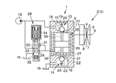
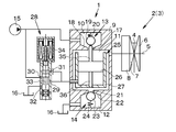
- the hydraulic control valve 1 shown in FIGS. 1 to 3 is provided for supplying or discharging hydraulic pressure to a belt type continuously variable transmission mounted on a vehicle.
- the belt-type continuously variable transmission is driven by the primary pulley 2 that is rotated by the power transmitted from the power source and the power of the primary pulley 2 is transmitted.
- a secondary pulley 3 that transmits power to the wheels and a belt 4 that transmits power to the pulleys 2 and 3 by being wound around the pulleys 2 and 3 are configured.
- pulleys 2 and 3 are constituted by a fixed sheave 6 that is formed integrally with the rotary shaft 5 and a movable sheave 7 that is arranged to face the fixed sheave 6 and is held so as to be movable along the rotary shaft 5.
- An actuator 8 is attached to the back surface of the movable sheave 7, that is, the surface opposite to the surface facing the fixed sheave 6. Therefore, by increasing or decreasing the hydraulic pressure of the actuator 8, the movable sheave 7 moves along the rotary shaft 5 or changes the load that sandwiches the belt 4. Since the basic configuration of each pulley 2 and 3 is substantially the same, one pulley 2 is shown in the figure.
- the hydraulic control valve 1 can be mounted on the actuator 8 configured to supply or discharge hydraulic pressure as described above, and the hydraulic control valve 1 will be specifically described below. To do.
- the hydraulic control valve 1 shown in FIGS. 1 to 3 includes three hydraulic chambers 10, 11, 12 formed inside a case 9, and each hydraulic chamber 10, 11, 12 is constituted by a supply valve 13 and a discharge valve 14. It is partitioned. Specifically, a first hydraulic chamber 10 to which hydraulic pressure is supplied from an oil pump 15 that is a hydraulic source and a second hydraulic chamber 11 that communicates with the actuator 8 are partitioned by a supply valve 13, and other members and oil pans ( Hereinafter, the third hydraulic chamber 12 communicated with the oil pan 16 and the second hydraulic chamber 11 are partitioned by a discharge valve 14.
- valves 13 and 14 are configured to block the hydraulic pressure of the hydraulic chambers 10, 11 and 12 by pressing the valve body against the valve seat by the elastic force of the elastic body. That is, a valve seat 18 having a large opening area is provided on the first hydraulic chamber 10 side of the supply port 17 where the first hydraulic chamber 10 and the second hydraulic chamber 11 communicate with each other. 9 is configured such that the valve body 19 is pressed toward the valve seat 18 by a spring 20 connected to the inner surface of the valve body 9 and connected to the valve body 19 at the other end. Therefore, as long as no other force acts on the valve body 19, the first hydraulic chamber 10 and the second hydraulic chamber 11 are blocked by the valve body 19 being pressed against the valve seat 18.
- the discharge valve 14 has a valve seat having a large opening area on the third hydraulic chamber 12 side of the discharge port 21 communicating with the second hydraulic chamber 11 and the third hydraulic chamber 12. 22, and the valve body 23 is configured to be pressed toward the valve seat 22 by a spring 24 having one end connected to the valve seat 22 and the other end connected to the valve body 23. Yes. Therefore, as long as no other force acts on the valve body 23, the second hydraulic chamber 11 and the third hydraulic chamber 12 are blocked by the valve body 23 being pressed against the valve seat 22.
- the second hydraulic chamber 11 is provided with a valve opening mechanism 25 for opening the valve bodies 19 and 23 apart from the valve seats 18 and 22. Yes.
- the valve opening mechanism 25 drives the piston 26 by the differential pressure between the hydraulic pressure of the actuator 8 and the regulated pilot hydraulic pressure, thereby pressing the valve bodies 19 and 23 away from the valve seats 18 and 22. It is composed of.
- a cylindrical member 27 formed by closing the lower end portion inside the second hydraulic chamber 11 is arranged with a gap from the case 9 so that the inside of the cylindrical member 27 is partitioned vertically. Is provided with a piston 26.
- the cylindrical member 27 and the case 9 are partially connected by a spacer or a fastening member (not shown).
- an output port 29 of a linear solenoid valve 28 communicates with a lower portion of the piston 26 in the cylindrical member 27 so that a pilot hydraulic pressure adjusted by the linear solenoid valve 28 is supplied.
- the valve opening mechanism 25 described above is formed so that the upper end portion of the cylindrical member 27 is opened, so that the hydraulic pressure of the second hydraulic chamber 11, that is, the hydraulic pressure of the actuator 8 is supplied. Further, the lower portion of the piston 26 in the cylindrical member 27 is configured such that pilot hydraulic pressure is supplied from the linear solenoid valve 28. Therefore, a load based on the hydraulic pressure of the actuator 8 acts on the piston 26 from above, and a load based on the pilot hydraulic pressure regulated by the linear solenoid valve 28 acts on the piston 26 from below.
- the linear solenoid valve 28 shown in the figure includes an input port 30 to which hydraulic pressure is supplied from the hydraulic source 15, and an output port 29 for discharging the hydraulic pressure to the actuator 8. , A feedback port 31 for feeding back the hydraulic pressure output from the output port 29, and a drain port 32 for draining the hydraulic pressure from the linear solenoid valve 28 to the oil pan 16, and each of these ports 29, 30, 31, A valve body 33 for selectively communicating 32 is disposed inside the linear solenoid valve 28, and a solenoid 34 for applying an electromagnetic force to the valve body 33 is provided.
- the valve body 33 is set according to the electric power flowing through the solenoid 34. It can be driven. Therefore, the hydraulic pressure output from the linear solenoid valve 28 can be controlled by controlling the power supplied to the solenoid 34.
- rods 35 and 36 for pressing the valve bodies 19 and 23 are integrally formed on the upper surface and the lower surface of the piston 26. That is, when the piston 26 is driven either up or down, the valve bodies 19 and 23 provided on the supply valve 13 or the discharge valve 14 are pressed by the rods 35 and 36 to be opened.
- the rod 36 formed in the lower portion of the piston 26 is formed so as to penetrate the lower end portion of the cylindrical member 27.
- the hydraulic control valve 1 By configuring the hydraulic control valve 1 as described above, it is possible to control the hydraulic pressure of the actuator 8 by controlling the pilot hydraulic pressure, that is, by controlling the power supplied to the solenoid 34 provided in the linear solenoid valve 28. it can. Specifically, in a state where the hydraulic pressure of the actuator 8 and the pilot hydraulic pressure are in balance, the piston 26 does not press the valves 13 and 14 to open, so that the hydraulic pressure of the actuator 8 can be kept constant. it can.
- the pilot is based on the load based on the hydraulic pressure of the actuator 8 acting on the piston 26.
- the load based on the hydraulic pressure increases, and the piston 26 moves toward the supply valve 13 as shown in FIG.
- the force for moving the piston 26 is greater than the load based on the spring force that presses the valve body 19 and the hydraulic pressure of the hydraulic source 15
- the valve body 19 is separated from the valve seat 18 and the hydraulic pressure from the hydraulic source 15 is increased. It is supplied to the actuator 8 through the first hydraulic chamber 10 and the second hydraulic chamber 11. That is, the hydraulic pressure of the actuator 8 can be increased.
- the hydraulic control valve 1 can control the hydraulic pressure of the actuator 8 by utilizing the pilot hydraulic pressure, the hydraulic pressure of the actuator 8 is large or high.
- the hydraulic pressure of the actuator 8 can be controlled by setting the pilot hydraulic pressure according to the conditions, and the enlargement of the hydraulic control valve 1 can be suppressed or prevented.
- the valves 13 and 14 are configured to press the valve bodies 19 and 23 against the valve seats 18 and 22, leakage of hydraulic pressure from the actuator 8 can be suppressed or prevented. Controllability and responsiveness can be improved.
- the hydraulic control valve 1 according to the present invention mounts on the primary pulley 2 side, the hydraulic pressure can be maintained in the actuator 8 even when the electronic control unit does not operate. Therefore, when the vehicle is towed, the rotating shaft 5 rotates, whereby centrifugal hydraulic pressure is generated in the actuator 8 and the winding radius of the belt 4 can be increased. As a result, since the rotational speed on the input side of the belt type continuously variable transmission can be reduced, wear and noise of each member can be suppressed or prevented.
- the pilot hydraulic pressure is supplied to the hydraulic control valve 1 using the linear solenoid valve 28.
- the hydraulic pressure of the actuator 8 is large, the piston 26 is driven.
- the pilot hydraulic pressure is increased, and as a result, the solenoid 34 provided in the linear solenoid valve 28 is increased in order to increase the electromagnetic force, and the linear solenoid valve 28 is increased in size. Accordingly, the leakage of hydraulic pressure from the linear solenoid valve 28 is relatively increased. Therefore, a configuration example of the hydraulic control valve 1 that can reduce the size of the linear solenoid valve 28 will be described.
- FIG. 4 is a diagram for explaining the configuration example, in which the shape of the piston 26 in the configuration example described above is changed.
- another piston 37 having a small hydraulic pressure receiving area is integrally formed on the upper surface of the piston 26, and the opening of the cylindrical member 27 has an inner diameter substantially equal to the outer diameter of the other piston 37.
- the inside of the opening of the cylindrical member 27 is configured to be driven.
- a load based on the hydraulic pressure in the second hydraulic chamber 11 acts on the upper surface of the other piston 37
- a load based on the pilot hydraulic pressure acts on the lower surface of the piston 26.
- the hydraulic pressure can be set low.
- the linear solenoid valve 28 that supplies the pilot hydraulic pressure to the hydraulic control valve 1 can be reduced.
- a pressure reducing valve 38 is disposed between the hydraulic power source 15 and the linear solenoid valve 28 in order to reduce the hydraulic pressure supplied to the linear solenoid valve 28 based on making the linear solenoid valve 28 smaller.
- a port 39 communicating with the outside of the hydraulic control valve 1 is formed between the upper surface of the piston 26 and the opening of the cylindrical member 27 in the figure, but this is connected to the other piston 37 and the cylindrical member 27. Since there is not a little gap, pressure oil may flow between the piston 26 and the opening of the cylindrical member 27. Therefore, by providing a port 39 for discharging the pressure oil to the oil pan 16, the piston This is to reduce or prevent a power loss that compresses the pressure oil when 26 is driven.
- the hydraulic control valve 1 is not limited to the above-described configuration because the hydraulic pressure of the actuator 8 can be controlled by controlling the pilot hydraulic pressure and leakage of the hydraulic pressure can be reduced.
- 5 to 7 may be used. 5 shows a state where the hydraulic pressure of the actuator 8 is kept constant, FIG. 6 shows a state where the hydraulic pressure is supplied to the actuator 8, and FIG. 7 shows a state where the hydraulic pressure of the actuator 8 is discharged. is there.
- the configuration of the hydraulic control valve 40 shown in FIGS. 5 to 7 will be described.
- the first hydraulic chamber 10, the second hydraulic chamber 11, and the third hydraulic chamber 12 are linearly arranged.
- the hydraulic control valve 40 shown here is similar to the first hydraulic chamber 10 and the first hydraulic chamber 10.
- the third hydraulic chamber 12 is arranged on the left and right, respectively, and the second hydraulic chamber 11 is arranged in the lower part of the first hydraulic chamber 10 and the third hydraulic chamber 12 so as to communicate with the respective hydraulic chambers 10 and 13. Yes.
- the first hydraulic chamber 10 houses a supply valve 13 composed of a spring 20 and a valve body 19 having one end connected to the case 9 and the other end connected to the valve body 19.
- a valve body 19 is configured to be pressed by a spring 20 against a valve seat 18 having a large opening area on the first hydraulic chamber 10 side of the supply port 17 communicating with the second hydraulic chamber 11.
- the third hydraulic chamber 12 houses a discharge valve 14 configured substantially the same as the supply valve 13.
- the discharge valve 14 is configured such that a valve body 23 is pressed by a spring 24 against a valve seat 22 having a large opening area on the third hydraulic chamber 12 side of the drain port 41.
- a rod 42 extending downward is integrally formed. The operation of the rod 42 formed on the discharge valve 14 will be described later.
- the hydraulic control valve 40 shown in the figure includes a piston 26 so as to partition the second hydraulic chamber 11 vertically, and is configured so that pilot hydraulic pressure is supplied to a lower portion of the piston 26. Further, a rod 35 is integrally formed on the left side of the piston 26 in the left-right direction shown in the drawing, that is, on the first hydraulic chamber 10 side, and upwards as shown in the drawing, and on the right side of the piston 26, that is, on the third hydraulic chamber 12 side. A through hole 43 through which the rod 42 formed in the discharge valve 14 described above passes is formed. In addition, in order to prevent the rod 42 from coming out of the through hole 43 formed in the piston 26 at the lower end portion of the rod 42 formed in the discharge valve 14, a retainer having an outer diameter larger than the diameter of the through hole 43. Are integrally formed.
- the hydraulic control valve 40 By forming the hydraulic control valve 40 in this way, a load based on the pilot hydraulic pressure can be applied from the lower part of the piston 26, and a load based on the hydraulic pressure of the actuator 8 can be applied from the upper part. By doing so, the hydraulic pressure of the actuator 8 can be controlled. That is, when the hydraulic pressure of the actuator 8 is increased, by increasing the pilot hydraulic pressure, the piston 26 moves upward as shown in FIG. 6 and the rod 35 moves the valve element 19 of the supply valve 13 from the valve seat 18. As a result, the hydraulic pressure is supplied from the hydraulic source 15 to the actuator 8 via the first hydraulic chamber 10 and the second hydraulic chamber 11.
- the hydraulic pressure of the actuator 8 can be controlled in accordance with the pilot hydraulic pressure in the same manner as the hydraulic control valve 1 described above.
- 14 is configured to close the valve body 19 and 23 by pressing the valve bodies 19 and 23 against the valve seats 18 and 22, so that leakage of hydraulic pressure from the hydraulic control valve 40 can be suppressed or prevented.
- the hydraulic control valves 1 and 40 according to the present invention need only be able to control the hydraulic pressure of the actuator 8 by the pilot hydraulic pressure. Therefore, the hydraulic control valves 1 and 40 do not use the linear solenoid valve 28 as in the above-described configuration examples. 8, a hydraulic pressure supply solenoid valve 45 and a hydraulic pressure discharge solenoid valve 46 may be used.
- the solenoid valves 45 and 46 shown in FIG. 8 are so-called poppet type solenoid valves known in the art, and the valve body 45a (46a) and the valve body 45a (46a) are connected to the input port 45b (46b).
- the solenoid valves 45 and 46 may be duty solenoid valves or proportional solenoid valves for more precise control.
- a target engine output is determined from the accelerator opening and the vehicle speed (step S1).
- the vehicle speed in step S1 can be obtained by detecting the number of rotations of the drive shaft, the number of rotations of the drive wheels, the number of rotations of other rotating members, and the like, and calculating from the detected values.
- the target rotational speed of the primary pulley 2 is determined from the target engine output determined in step S1 (step S2).
- the target rotational speed of the primary pulley 2 in step S2 can be determined by using an optimal fuel consumption line of the engine determined in advance by experiments or the like from the target engine output and the accelerator opening. Further, the actual rotational speed of the primary pulley 2 is measured simultaneously with step S2 or after step S2 (step S3), and the deviation of the rotational speed of the primary pulley 2 is calculated from the actual rotational speed of the primary pulley 2 and the target rotational speed. Calculate (step S4).
- step S5 it is determined whether or not the deviation calculated in step S4 is 0 (zero) (step S5). If the determination in step S5 is affirmative, that is, if the deviation is 0 (zero), there is no need to change the gear ratio, so that the hydraulic pressure is not changed in the hydraulic control valve 1, that is, the hydraulic pressure
- This routine is temporarily terminated without supplying power to the supply solenoid valve 45 and the hydraulic pressure discharge solenoid valve 46 (step S6).
- step S7 it is determined whether or not the deviation is positive. If the determination in step S7 is affirmative, that is, if the actual rotational speed is greater than the target rotational speed, an upshift is performed to decrease the rotational speed of the primary pulley 2. That is, the rotational speed of the primary pulley 2 is reduced by increasing the hydraulic pressure of the actuator 8 attached to the primary pulley 2. Specifically, the electric power obtained by integrating the predetermined value ⁇ with the deviation is supplied to the hydraulic pressure discharge solenoid valve 46 (step S8), and this routine is temporarily ended.
- the predetermined value ⁇ is a coefficient used when an electric power corresponding to a deviation in the rotational speed is determined in advance by an experiment or the like and converted from the deviation to electric power.
- step S7 If a negative determination is made in step S7, that is, if the actual rotational speed is smaller than the target rotational speed, a downshift is performed to increase the rotational speed of the primary pulley 2. That is, the rotational speed of the primary pulley 2 is increased by reducing the hydraulic pressure of the actuator 8 attached to the primary pulley 2. Specifically, the electric power obtained by integrating the predetermined value ⁇ with the deviation is supplied to the hydraulic pressure supply solenoid valve 46 (step S9), and this routine is temporarily ended.
- the pilot hydraulic pressure can be controlled by controlling the power supplied to the hydraulic pressure supply solenoid valve 45 and the hydraulic pressure discharge solenoid valve 46, and as a result, the hydraulic pressure of the actuator 8 can be controlled. it can.
- the hydraulic control valves 1 and 40 according to the present invention have been described as examples mounted on a vehicle.
- the present invention is not particularly limited thereto, and may be used for, for example, an aircraft, a ship, or an industrial device. You can also.
Landscapes
- Engineering & Computer Science (AREA)
- General Engineering & Computer Science (AREA)
- Physics & Mathematics (AREA)
- Mechanical Engineering (AREA)
- Fluid Mechanics (AREA)
- General Physics & Mathematics (AREA)
- Automation & Control Theory (AREA)
- Fluid-Driven Valves (AREA)
- Multiple-Way Valves (AREA)
Abstract
La présente invention porte sur une vanne de commande hydraulique destinée à commander la pression hydraulique dans un actionneur (8) en fournissant de la pression hydraulique à l'actionneur (8) ou en en relâchant de la pression hydraulique. La présente invention comprend un élément mobile (26) apte à agir dans le sens dans lequel la pression hydraulique régnant dans l'actionneur et la pression hydraulique de commande réglée sur une pression prédéterminée agissent l'une contre l'autre. L'élément mobile (26) est conçu de telle sorte que, lorsqu'une charge due à la pression hydraulique régnant dans l'actionneur est inférieure à une charge due à la pression hydraulique de commande, l'élément mobile (26) écarte un premier obturateur (19) d'un premier siège de soupape (18) pour ouvrir une soupape d'alimentation (13) et que, lorsque la charge due à la pression hydraulique régnant dans l'actionneur est supérieure à la charge due à la pression hydraulique de commande, l'élément mobile (26) écarte un second obturateur (23) d'un second siège de soupape (22) pour ouvrir une soupape de décharge (14).
Priority Applications (2)
| Application Number | Priority Date | Filing Date | Title |
|---|---|---|---|
| JP2012556696A JP5522277B2 (ja) | 2011-02-09 | 2011-02-09 | 油圧制御弁 |
| PCT/JP2011/052752 WO2012108013A1 (fr) | 2011-02-09 | 2011-02-09 | Vanne de commande hydraulique |
Applications Claiming Priority (1)
| Application Number | Priority Date | Filing Date | Title |
|---|---|---|---|
| PCT/JP2011/052752 WO2012108013A1 (fr) | 2011-02-09 | 2011-02-09 | Vanne de commande hydraulique |
Publications (1)
| Publication Number | Publication Date |
|---|---|
| WO2012108013A1 true WO2012108013A1 (fr) | 2012-08-16 |
Family
ID=46638256
Family Applications (1)
| Application Number | Title | Priority Date | Filing Date |
|---|---|---|---|
| PCT/JP2011/052752 Ceased WO2012108013A1 (fr) | 2011-02-09 | 2011-02-09 | Vanne de commande hydraulique |
Country Status (2)
| Country | Link |
|---|---|
| JP (1) | JP5522277B2 (fr) |
| WO (1) | WO2012108013A1 (fr) |
Citations (6)
| Publication number | Priority date | Publication date | Assignee | Title |
|---|---|---|---|---|
| JPS4981093A (fr) * | 1972-12-08 | 1974-08-05 | ||
| JPS5315619A (en) * | 1976-07-28 | 1978-02-13 | Obayashi Gumi Kk | Switch device for super high oil pressure |
| JPS58113107U (ja) * | 1982-01-26 | 1983-08-02 | エスエムシ−株式会社 | 圧力制御弁 |
| JPS59121263A (ja) * | 1982-12-28 | 1984-07-13 | Saginomiya Seisakusho Inc | 冷凍装置用三方切換弁 |
| JPH0446201A (ja) * | 1990-06-08 | 1992-02-17 | Takashi Kimura | 空圧シリンダ用切換弁 |
| JPH0763275A (ja) * | 1993-08-24 | 1995-03-07 | Toyooki Kogyo Co Ltd | パイロット操作切換弁 |
Family Cites Families (1)
| Publication number | Priority date | Publication date | Assignee | Title |
|---|---|---|---|---|
| DE19841346A1 (de) * | 1998-09-10 | 2000-03-16 | Volkswagen Ag | Stufenlos verstellbares Kegelscheibenumschlingungsgetriebe, insbesondere für Kraftfahrzeuge |
-
2011
- 2011-02-09 JP JP2012556696A patent/JP5522277B2/ja not_active Expired - Fee Related
- 2011-02-09 WO PCT/JP2011/052752 patent/WO2012108013A1/fr not_active Ceased
Patent Citations (6)
| Publication number | Priority date | Publication date | Assignee | Title |
|---|---|---|---|---|
| JPS4981093A (fr) * | 1972-12-08 | 1974-08-05 | ||
| JPS5315619A (en) * | 1976-07-28 | 1978-02-13 | Obayashi Gumi Kk | Switch device for super high oil pressure |
| JPS58113107U (ja) * | 1982-01-26 | 1983-08-02 | エスエムシ−株式会社 | 圧力制御弁 |
| JPS59121263A (ja) * | 1982-12-28 | 1984-07-13 | Saginomiya Seisakusho Inc | 冷凍装置用三方切換弁 |
| JPH0446201A (ja) * | 1990-06-08 | 1992-02-17 | Takashi Kimura | 空圧シリンダ用切換弁 |
| JPH0763275A (ja) * | 1993-08-24 | 1995-03-07 | Toyooki Kogyo Co Ltd | パイロット操作切換弁 |
Also Published As
| Publication number | Publication date |
|---|---|
| JPWO2012108013A1 (ja) | 2014-07-03 |
| JP5522277B2 (ja) | 2014-06-18 |
Similar Documents
| Publication | Publication Date | Title |
|---|---|---|
| JP5170255B2 (ja) | シーブ位置決め装置 | |
| US8925699B2 (en) | Powertrain pressure and flow control system for automatic transmissions | |
| JP2014234909A (ja) | 無段変速機の流体圧ポンプの固着判定装置 | |
| JP5522277B2 (ja) | 油圧制御弁 | |
| US10316960B2 (en) | Method and device for controlling automatic transmission | |
| WO2013183162A1 (fr) | Organe de commande hydraulique | |
| WO2014097468A1 (fr) | Dispositif de commande hydraulique | |
| JP2012031955A (ja) | 自動変速機の油圧制御装置 | |
| US20190390768A1 (en) | Hydraulic control device for automatic transmission | |
| JP2013160379A (ja) | 油圧制御装置 | |
| JP5655960B2 (ja) | 油圧制御回路 | |
| JP2011127658A (ja) | 無段変速機の油圧制御装置 | |
| JP2011052797A (ja) | ベルト式無段変速機の油圧制御装置 | |
| JP4649998B2 (ja) | 無段変速機の受圧面差を伴う変速制御装置 | |
| JP2013241956A (ja) | 油圧制御装置 | |
| JP2014202348A (ja) | 自動変速機の油圧制御装置 | |
| JP5131157B2 (ja) | 閉じ込み制御装置 | |
| JP2625748B2 (ja) | 車両用ベルト式無段変速機の油圧制御装置 | |
| JP5115322B2 (ja) | ベルト式無段変速機 | |
| JP2012132493A (ja) | 自動変速機の油圧制御装置 | |
| JP2625745B2 (ja) | 車両用ベルト式無段変速機の油圧制御装置 | |
| JP2840718B2 (ja) | 車両用ベルト式無段変速機の油圧制御装置 | |
| JP5282771B2 (ja) | 自動変速機の油圧制御装置 | |
| JP2748369B2 (ja) | 車両用ベルト式無段変速機の油圧制御装置 | |
| JP2018112240A (ja) | 自動変速機の油圧制御装置 |
Legal Events
| Date | Code | Title | Description |
|---|---|---|---|
| 121 | Ep: the epo has been informed by wipo that ep was designated in this application |
Ref document number: 11858222 Country of ref document: EP Kind code of ref document: A1 |
|
| DPE1 | Request for preliminary examination filed after expiration of 19th month from priority date (pct application filed from 20040101) | ||
| ENP | Entry into the national phase |
Ref document number: 2012556696 Country of ref document: JP Kind code of ref document: A |
|
| NENP | Non-entry into the national phase |
Ref country code: DE |
|
| 122 | Ep: pct application non-entry in european phase |
Ref document number: 11858222 Country of ref document: EP Kind code of ref document: A1 |