WO2012108155A1 - Dispositif de station de base et procédé de transmission - Google Patents
Dispositif de station de base et procédé de transmission Download PDFInfo
- Publication number
- WO2012108155A1 WO2012108155A1 PCT/JP2012/000732 JP2012000732W WO2012108155A1 WO 2012108155 A1 WO2012108155 A1 WO 2012108155A1 JP 2012000732 W JP2012000732 W JP 2012000732W WO 2012108155 A1 WO2012108155 A1 WO 2012108155A1
- Authority
- WO
- WIPO (PCT)
- Prior art keywords
- base station
- configuration
- abs
- henb
- configuration pattern
- Prior art date
- Legal status (The legal status is an assumption and is not a legal conclusion. Google has not performed a legal analysis and makes no representation as to the accuracy of the status listed.)
- Ceased
Links
Images


Classifications
-
- H—ELECTRICITY
- H04—ELECTRIC COMMUNICATION TECHNIQUE
- H04W—WIRELESS COMMUNICATION NETWORKS
- H04W24/00—Supervisory, monitoring or testing arrangements
- H04W24/02—Arrangements for optimising operational condition
-
- H—ELECTRICITY
- H04—ELECTRIC COMMUNICATION TECHNIQUE
- H04W—WIRELESS COMMUNICATION NETWORKS
- H04W72/00—Local resource management
- H04W72/20—Control channels or signalling for resource management
- H04W72/23—Control channels or signalling for resource management in the downlink direction of a wireless link, i.e. towards a terminal
-
- H—ELECTRICITY
- H04—ELECTRIC COMMUNICATION TECHNIQUE
- H04W—WIRELESS COMMUNICATION NETWORKS
- H04W24/00—Supervisory, monitoring or testing arrangements
- H04W24/10—Scheduling measurement reports ; Arrangements for measurement reports
-
- H—ELECTRICITY
- H04—ELECTRIC COMMUNICATION TECHNIQUE
- H04W—WIRELESS COMMUNICATION NETWORKS
- H04W84/00—Network topologies
- H04W84/02—Hierarchically pre-organised networks, e.g. paging networks, cellular networks, WLAN [Wireless Local Area Network] or WLL [Wireless Local Loop]
- H04W84/04—Large scale networks; Deep hierarchical networks
- H04W84/042—Public Land Mobile systems, e.g. cellular systems
- H04W84/045—Public Land Mobile systems, e.g. cellular systems using private Base Stations, e.g. femto Base Stations, home Node B
-
- H—ELECTRICITY
- H04—ELECTRIC COMMUNICATION TECHNIQUE
- H04W—WIRELESS COMMUNICATION NETWORKS
- H04W88/00—Devices specially adapted for wireless communication networks, e.g. terminals, base stations or access point devices
- H04W88/08—Access point devices
-
- H—ELECTRICITY
- H04—ELECTRIC COMMUNICATION TECHNIQUE
- H04W—WIRELESS COMMUNICATION NETWORKS
- H04W92/00—Interfaces specially adapted for wireless communication networks
- H04W92/16—Interfaces between hierarchically similar devices
- H04W92/20—Interfaces between hierarchically similar devices between access points
Definitions
- the present invention relates to a base station apparatus and a transmission method.
- a small base station device has been developed to form a cell having a smaller communication area than a conventional cell.
- a small base station apparatus for example, there are devices called PicoPeNB and Home eNB (in the following description, these are collectively referred to as HeNB for convenience).
- HeNB is laid for the purpose of covering only a limited narrow area such as in each home or office. Therefore, compared with a large base station apparatus (macro base station (Macro eNB), hereinafter referred to as MeNB)) for forming a cell having a large communication area, the HeNB has a small cell, and thus traffic concentration. Congestion hardly occurs and high throughput can be expected.
- Macro base station Micro eNB
- the HeNB (particularly the HeNB installed in the home) can be changed by the end user to an arbitrary location, and it is difficult for the communication carrier to manage the operational status of the HeNB.
- the HeNB uses the same frequency band as MeNB (macro base station), it becomes a problem that interference may arise between HeNB and MeNB.
- FIG. 1 is a diagram for explaining interference that occurs between the HeNB and the MeNB.
- one HeNB is installed in the communication area of the MeNB, and a mobile station (Macro User Equipment; hereinafter referred to as MUE) communicating with the MeNB is located (located).
- MUE Micro User Equipment
- HUE Home User Equipment
- the HUE when the distance between the MeNB and the HeNB is relatively short, the HUE receives not only the downlink signal (solid line) from the HeNB that is the desired wave but also the downlink signal (dashed line) from the MeNB that is the interference wave. It will be. In this case, there is a problem that the reception quality of the HUE deteriorates and the throughput decreases.
- the MUE shown in FIG. 1 approaches the HeNB communication area, the MUE receives not only the downlink signal (desired wave) from the MeNB but also the downlink signal (interference wave) from the HeNB. In this case, the MUE receives interference, which causes a problem that the reception quality of the MUE deteriorates and the throughput decreases.
- Non-Patent Document 1 As a method for solving this problem, for example, a method called ABS (Almost Blank Subframe) disclosed in Non-Patent Document 1 has been studied.
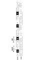
- the MeNB periodically stops transmission (downlink transmission) on the downlink.
- downlink transmission is stopped by the MeNB setting a non-transmission subframe every 4 subframes.
- the interfered base station (victim. HeNB in FIG. 2) receives interference.
- the throughput of UEs located in the interfered base station is improved.
- Non-Patent Document 1 when transmission is stopped using ABS, throughput is reduced due to no transmission in the interfering base station (MeNB).
- MeNB interfering base station
- FIG. 2 when a MeNB with a wide coverage stops transmission, the number of terminals (MUEs) that are affected by a decrease in throughput due to no transmission increases, resulting in a decrease in throughput of the entire network. It will be connected.
- An object of the present invention is to provide a base station apparatus and a transmission method capable of minimizing interference between base stations (MeNB and HeNB) and improving the throughput of the entire network.
- the base station apparatus is a subframe configuration pattern represented by a combination of a transmission subframe that transmits a signal and a non-transmission subframe that stops signal transmission.
- a determination unit that determines a configuration pattern used by the own device from a plurality of configuration patterns; a transmission unit that transmits a signal to a terminal device connected to the own device according to the determined configuration pattern; The structure which comprises is taken.
- a transmission method is a subframe configuration pattern represented by a combination of a transmission subframe for transmitting a signal and a non-transmission subframe for stopping signal transmission,
- the plurality of base station apparatuses based on presence / absence of interference between the own apparatus and another base station apparatus other than the own apparatus
- the configuration pattern used by the own device is determined from among the configuration patterns, and a signal is transmitted to the terminal device connected to the own device according to the determined configuration pattern.
- the present invention it is possible to minimize interference between base stations (MeNB and HeNB) and improve the throughput of the entire network.
- the figure which shows the structure of the network system which consists of MeNB and HeNB Diagram for explaining ABS The figure which shows the structure of the network system which concerns on Embodiment 1 of this invention.
- the block diagram which shows the structure of the small base station which concerns on Embodiment 1 of this invention.
- the figure which shows the ABS pattern which concerns on Embodiment 1 of this invention The figure which shows the ABS white list which concerns on Embodiment 1 of this invention.
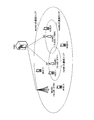
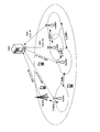
- FIG. 3 shows a configuration example of a network system (communication system) according to the present embodiment.
- the cell ID is a number assigned uniquely to the base station.
- MUEs 11 to 13 are located in the communication area of MeNB1, HUE11 is located in the communication area of HeNB1, and HUE21 is located in the communication area of HeNB2.
- each base station (MeNB and HeNB) located in the network system shown in FIG. 3 transmits a signal using one of a plurality of different ABS patterns.
- the ABS pattern is a subframe configuration pattern represented by a combination of a transmission subframe that transmits a signal and a non-transmission subframe that stops signal transmission.
- OMC Operaation and Maintenance Center
- MeNB2 HeNB1 and HeNB2 as well as MeNB2 and MeNB3 (not shown), respectively.
- a management device having a function of managing a configuration).
- FIG. 4 is a block diagram showing the configuration of the HeNB (for example, HeNB1 and HeNB2 shown in FIG. 3).
- the HeNB 100 illustrated in FIG. 4 collects information (cell ID and the like) of neighboring base stations (MeNB and HeNB) immediately after power-on.
- HeNB100 may perform this information collection regularly (for example, once a day).
- the receiving unit 101 receives downlink signals (downlink radio signals) from neighboring base stations (MeNB and HeNB) when the HeNB 100 is powered on.
- the received signal includes, for example, a reference signal, a synchronization signal, an ABS configuration transmitted from another base station, and the like. Note that the ABS configuration is transmitted (broadcast) on a broadcast channel, for example.
- the receiving unit 101 outputs the received downlink signal to the searching unit 103.
- the control unit 102 instructs the search unit 103 to search for a base station located in the vicinity of the HeNB 100, using the power-on of the HeNB 100 as a trigger. For example, the control unit 102 instructs the search unit 103 to measure RSRQ (Reference Signal Received Quality).
- RSRQ Reference Signal Received Quality
- Search unit 103 searches for base stations located around HeNB 100 and is used by base stations located around HeNB 100 in accordance with instructions from control unit 102 (that is, triggered by power-on of HeNB 100).
- ABS Configuration that is, ABS pattern
- the search unit 103 searches for other base stations (MeNB and HeNB) located in the vicinity of the own device based on the downlink signal (synchronization signal) received by the reception unit 101.
- the search part 103 specifies the searched other base station as an apparatus with which interference occurs with an own apparatus.
- the search unit 103 monitors broadcast channels from other searched base stations, and acquires an ABS configuration indicating an ABS pattern used by the base station.
- the search part 103 measures RSRQ using the reference signal from the searched other base station.
- the smaller the measured value of RSRQ the smaller the amount of interference with HeNB 100.
- the search unit 103 outputs the acquired ABS configuration to the determination unit 104. Note that details of the search processing of the neighboring base stations in the search unit 103 will be described later.
- the determination unit 104 determines the ABS configuration used by the HeNB 100 based on the ABS configuration acquired by the search unit 103. For example, the determination unit 104 uses an ABS configuration (ABS) that the HeNB 100 uses, from among a plurality of ABS configurations (ABS patterns) that can be set in the HeNB 100, an ABS configuration that is different from the ABS configuration collected by the search unit 103. Pattern). That is, the determination unit 104 determines any ABS configuration other than the ABS configuration used by the peripheral base station of the HeNB 100 (an apparatus that causes interference with the HeNB 100) as the ABS configuration used by the HeNB 100. Then, the determination unit 104 outputs the determined ABS configuration (ABS pattern) to the transmission unit 105. Details of the ABS Configuration determination process in the determination unit 104 will be described later.
- the HeNB 100 applies the ABS configuration determined by the determination unit 104 to the UE (HUE) connected to the HeNB 100. Therefore, the transmission part 105 transmits a signal with respect to the terminal (HUE) connected to the own apparatus according to the ABS ⁇ ⁇ ⁇ ⁇ Configuration (ABS pattern) determined by the determination part 104. Further, the transmission unit 105 reports the ABS configuration (ABS configuration used by the HeNB 100) input from the determination unit 104 to the OMC.
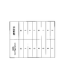
- each base station such as MeNB and HeNB (including HeNB100) has an ABS Configuration table as shown in FIG. 5, for example.
- m represents a counter that increases every subframe. That is, transmission / non-transmission on the downlink for 40 subframes is defined in the ABS pattern C ABS (m) shown in FIG.
- a subframe in which a downlink signal is transmitted is represented by “0”
- a subframe in which transmission of the downlink signal is stopped is represented by “1”.
- each base station such as MeNB and HeNB (including HeNB 100) has an ABS white list indicating an ABS configuration that can be used by the own apparatus, as shown in FIG. 6, for example.
- the ABS Configuration corresponding to the parameter “1” is usable, and the ABS Configuration corresponding to the parameter “0” is unusable.
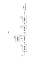
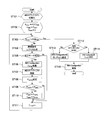
- FIG. 7 shows a flowchart showing the flow of the search process of the neighboring base station and the determination process of the ABS configuration in the HeNB 100 according to the present embodiment.
- processing in HeNB2 (during suspension) in FIG. 3 will be described.
- search unit 103 of HeNB2 initializes an ABS white list (see, for example, FIG. 6). Specifically, the search unit 103 initializes all the availability states of the ABS configuration shown in the ABS white list to usable ('1').
- search section 103 determines whether or not the cell ID (T PCID ) to be measured exceeds PCID MAX .
- search section 103 When the measurement target cell ID (T PCID ) does not exceed PCID MAX (ST103: No), in ST104, search section 103 generates a replica of the synchronization signal.
- synchronization signals There are two types of synchronization signals: a first synchronization signal (Primary Synchronization Signal: PSS) and a second synchronization signal (Secondary Synchronization Signal: SSS).
- search section 103 performs cell search using a replica of the synchronization signal (PSS and SSS) generated in ST104. Specifically, the search unit 103 performs a correlation operation between the received signal and the replica of the synchronization signal (PSS and SSS). Then, when the correlation value between the received signal and the replica of the synchronization signal is equal to or greater than a preset threshold, the search unit 103 has a base station of the measurement target cell ID (T PCID ) in the vicinity of the own device (HeNB2) (That is, the cell search is considered successful).
- T PCID measurement target cell ID
- HeNB2 the own device
- the search unit 103 determines that the base station of the measurement target cell ID (T PCID ) is not present in the vicinity of the own device (HeNB2). Judge (ie, consider cell search failure). If the cell search is successful (ST105: Yes), the process proceeds to ST106, and if the cell search is not successful (ST105: No), the process proceeds to ST111.
- search section 103 monitors the broadcast channel from the base station of the cell ID (T PCID ) to be measured, and collects the ABS Configuration (C PCID ) used by the base station.
- T PCID cell ID
- C PCID ABS Configuration
- search section 103 updates the ABS white list by setting the availability state corresponding to the ABS Configuration (C PCID ) collected in ST 106 to unavailable ('0') in the ABS white list. To do.
- search section 103 monitors the downlink reference signal from the base station of the cell ID (T PCID ) to be measured, and measures RSRQ (P RSRQ ).
- search section 103 compares the the P MIN RSRQ (P RSRQ) measured at ST 108. If P RSRQ is smaller than P MIN (ST109: Yes), in ST110, search section 103 updates P MIN to P RSRQ and C MIN to C PCID . By repeatedly performing the processing of ST108 to ST110 on the measurement target base station, the base station having the smallest RSRQ among the measurement target base stations (that is, the base station having the smallest amount of interference with the own device) ) Is used for the ABS Configuration (C MIN ). On the other hand, if P RSRQ is equal to or greater than P MIN (ST109: No), the process proceeds to ST111.
- search section 103 updates the measurement target base station by incrementing TPCID indicating the measurement target cell ID, and returns to the process of ST103.
- Search section 103 repeats the processing of ST 103 to 111 until T PCID becomes PCID MAX (until ST 103: Yes).
- the determination unit 104 determines the ABS configuration of HeNB2. Specifically, in ST112, the determination unit 104 refers to the ABS white list updated in ST107 and determines whether there is an ABS configuration that can be used in the own device (HeNB2) (that is, all ABS configurations are used). Whether or not it is impossible).
- the ABS configuration having the smallest number may be selected from the available ABS configurations. For example, in FIG. 5, the ABS Configuration with a smaller number has fewer non-transmission subframes. Therefore, by selecting the ABS Configuration having the smallest number, it is possible to reduce the number of non-transmission subframes that stop transmission of downlink signals as much as possible.
- the determination unit 104 uses the ABS Configuration (C MIN ) of the base station corresponding to the minimum RSRQ set in ST110 in its own device (HeNB2). Set to ABS Configuration. That is, when all of the plurality of ABS Configurations (ABS patterns) are used by a plurality of other base stations, the determination unit 104 has the smallest amount of interference with the own device among the plurality of other base stations.
- the ABS Configuration (ABS pattern) used by is determined as the ABS Configuration (ABS pattern) used by the own device.
- the transmission unit 105 reports to the OMC the ABS Configuration used by the own device, determined by the determination unit 104 in ST113 or ST114.
- the HeNB2 (HeNB100) illustrated in FIG. 3 regards a base station (for example, HeNB1) that can be detected by the own device as a base station that the own device can interfere with, and uses the ABS configuration that the base station uses. Set the ABS Configuration different from that in the local device.
- the base stations (HeNB1 and HeNB2) that interfere with each other use the same ABSAConfiguration, the non-transmission subframes are completely overlapped. As a result, interference between base stations that interfere with each other cannot be suppressed.
- different ABS configurations are used between base stations that interfere with each other (for example, HeNB1 and HeNB2).
- the interfered base station does not need to receive interference, and the throughput of the UE located in the interfered base station can be improved.
- the HeNB 100 sets the ABS Configuration (C MIN ) of the base station corresponding to the minimum RSRQ at its own device (HeNB2).
- C MIN ABS Configuration
- HeNB2 the HeNB 100 automatically sets the ABS Configuration of the neighboring base station with the smallest interference with the own device (the ABS Configuration of the base station corresponding to the minimum RSRQ).
- the HeNB100 and a periphery base station use the same ABS Configuration, it becomes possible to suppress the interference between the said base stations to the minimum.
- the HeNB 100 may determine the ABSAConfiguration of its own device so that different ABS Configurations are set with the base stations (base stations that can interfere with the HeNB 100) detected by the neighboring base station search. .
- the HeNB 100 may set the same ABS Configuration as the ABS Configuration used by a base station (a base station that cannot interfere with the HeNB 100) that is not detected by the neighboring base station search, in its own device. That is, HeNB100 (deciding part 104) is between base stations (HeNB100) searched by HeNB100 (search part 103) among a plurality of base stations (MeNB and HeNB) located in a network system (communication system).
- ABS Configuration ABS Configuration
- ABS Configuration ABS Configuration
- N HeNBs when there are N HeNBs in the communication area of the MeNB and the N HeNBs do not interfere with any HeNB (when each HeNB has not detected another HeNB), the N HeNBs are the same.
- Each ABS Configuration may be set.
- HeNB1 can interfere with MeNB and does not interfere with HeNB2-4. Therefore, the HeNB 1 sets an ABS configuration (ABS conf. # 1) different from the ABS configuration (ABS conf. # 0) of the MeNB. At this time, HeNB1 may set the same ABS Configuration (HeBS2 and HeNB4 ABS Conf. # 1 in FIG. 8) as HeNB2 to HeNB4 that do not interfere.
- HeNB4 can interfere with HeNB3 and does not interfere with MeNB, HeNB1, and HeNB2. Therefore, HeNB4 sets an ABS Configuration (ABS Conf.
- the HeNB 4 may set the same ABS Configuration as the MeNB, HeNB1, and HeNB2 that do not interfere (ABS Conf. # 1 of the HeNB1 and HeNB2 in FIG. 8).
- other base stations (MeNB, HeNB2, and HeNB3) set the ABS configuration of the own apparatus.
- each base station can select from a plurality of ABS configurations (ABS patterns) based on the presence / absence of interference between its own device and another base station other than its own device.
- each base station identifies a peripheral base station that can be detected by the own device as a device that causes interference with the own device, and is used by the neighboring base station. Set the ABS configuration that is different from the existing ABS configuration.
- each base station independently sets the optimum ABS configuration for the own device. Thereby, the interference between each base station can be suppressed to the minimum.
- Non-Patent Document 1 not only MeNB applies ABS, but HeNB can also reduce the number of non-transmission subframes in MeNB by applying ABS, improving throughput as a whole network. It becomes possible to do.
- the determination unit 104 monitors the ABS ⁇ ⁇ Configuration of the neighboring base stations. did.
- the HeNB 100 may monitor the ABS configuration of the peripheral base station in parallel with the search for the peripheral base station. As a result, it is possible to further reduce the processing amount of the search process for the neighboring base stations and the monitoring process for the ABS configuration.
- the HeNB searches for neighboring base stations, whereas in this embodiment, the HeNB does not search for neighboring base stations.
- HeNB which concerns on this Embodiment takes the structure which does not comprise the control part 102 and the search part 103 among HeNB100 which concerns on Embodiment 1 shown in FIG.
- the determination unit 104 measures the amount of interference from another base station (MeNB or HeNB) using the downlink signal received by the reception unit 101.
- the determination unit 104 increments the currently set ABS Configuration candidate and sets a new ABS ⁇ ⁇ Configuration candidate.
- the determination unit 104 determines the currently set ABSAConfiguration candidate as the ABS Configuration of the own device.
- the determination unit 104 determines the ABS Configuration (ABS pattern) in which the amount of interference from other base stations other than its own device is less than the threshold (allowable value) among the plurality of ABS Configurations (ABS patterns) It is determined as the ABS configuration (ABS pattern) used by the device itself.
- the transmission unit 105 reports the ABS configuration finally determined by the determination unit 104 to the OMC.
- each base station is based on the presence or absence of interference between the own apparatus and other base stations other than the own apparatus, from a plurality of ABS Configurations (ABS patterns), Determine the ABS configuration used by the device itself.
- ABS Configurations ABS patterns
- each base station uses an ABS configuration that has a small amount of interference with other base stations (the amount of interference is less than a threshold).
- the interfered base station does not need to receive interference, and the throughput of the UE located in the interfered base station can be improved.
- the HeNB 100 sets the ABS configuration corresponding to the minimum interference amount to the ABS configuration used in its own device when the interference amount exceeds the threshold in all ABS configurations. May be. That is, even if the amount of interference with other base stations cannot be less than the allowable value, the HeNB can minimize interference between base stations by setting the ABS Configuration with the smallest amount of interference in its own device. Is possible.
- the HeNB has been described as acquiring peripheral base station information when the power is turned on.
- the acquisition of the neighboring base station information in the HeNB may be performed periodically, for example, once a day.
- the HeNB reports the ABS configuration to the OMC.
- the HeNB may directly report an ABS pattern composed of a total of 40 bits shown in FIG. 5 to the OMC.
- the present invention is suitable for a mobile communication system having MeNB, MUE, HeNB and HUE.
Landscapes
- Engineering & Computer Science (AREA)
- Computer Networks & Wireless Communication (AREA)
- Signal Processing (AREA)
- Mobile Radio Communication Systems (AREA)
Abstract
Priority Applications (3)
| Application Number | Priority Date | Filing Date | Title |
|---|---|---|---|
| JP2012556780A JPWO2012108155A1 (ja) | 2011-02-10 | 2012-02-03 | 基地局装置及び送信方法 |
| US13/977,454 US20130279419A1 (en) | 2011-02-10 | 2012-02-03 | Base station device and transmitting method |
| EP12744287.9A EP2675225A1 (fr) | 2011-02-10 | 2012-02-03 | Dispositif de station de base et procédé de transmission |
Applications Claiming Priority (2)
| Application Number | Priority Date | Filing Date | Title |
|---|---|---|---|
| JP2011-027449 | 2011-02-10 | ||
| JP2011027449 | 2011-02-10 |
Publications (1)
| Publication Number | Publication Date |
|---|---|
| WO2012108155A1 true WO2012108155A1 (fr) | 2012-08-16 |
Family
ID=46638382
Family Applications (1)
| Application Number | Title | Priority Date | Filing Date |
|---|---|---|---|
| PCT/JP2012/000732 Ceased WO2012108155A1 (fr) | 2011-02-10 | 2012-02-03 | Dispositif de station de base et procédé de transmission |
Country Status (4)
| Country | Link |
|---|---|
| US (1) | US20130279419A1 (fr) |
| EP (1) | EP2675225A1 (fr) |
| JP (1) | JPWO2012108155A1 (fr) |
| WO (1) | WO2012108155A1 (fr) |
Cited By (4)
| Publication number | Priority date | Publication date | Assignee | Title |
|---|---|---|---|---|
| JP2014107667A (ja) * | 2012-11-27 | 2014-06-09 | Softbank Mobile Corp | マクロセル基地局、フェムトセル基地局、通信システム、基地局システム、リソース割り当て方法、分配方法、リソース割り当てプログラム、及び分配プログラム |
| WO2014176147A1 (fr) * | 2013-04-24 | 2014-10-30 | Alcatel Lucent | Procédé et appareil permettant une détermination d'un motif de sous-trame presque vierge par une écoute du réseau |
| US20150249530A1 (en) * | 2012-09-27 | 2015-09-03 | Broadcom Corporation | Method to coordinate resource allocation to address inter-cell interference |
| US20160006528A1 (en) * | 2013-03-06 | 2016-01-07 | Telefonaktiebolaget L M Ericsson (Publ) | Channel estimation for interference cancellation |
Families Citing this family (8)
| Publication number | Priority date | Publication date | Assignee | Title |
|---|---|---|---|---|
| JP5935583B2 (ja) * | 2012-08-07 | 2016-06-15 | 富士通株式会社 | 小規模基地局、通信システムおよび通信方法 |
| US10111250B2 (en) | 2014-01-21 | 2018-10-23 | Telefonaktiebolaget Lm Ericsson (Publ) | Methods and apparatuses for coordinating resource scheduling between wireless networks |
| US10004084B2 (en) | 2014-01-21 | 2018-06-19 | Telefonaktiebolaget Lm Ericsson (Publ) | Methods and apparatuses for coordinating resource scheduling between wireless networks |
| US10285064B2 (en) | 2014-04-09 | 2019-05-07 | Telefonaktiebolaget Lm Ericsson (Publ) | Method and apparatus for coordinating resources between different networks |
| CN106465346B (zh) | 2014-07-11 | 2020-02-21 | 华为技术有限公司 | 一种干扰协调方法和基站 |
| US9906973B2 (en) | 2014-11-28 | 2018-02-27 | Industrial Technology Research Institute | Evolved NodeB and traffic dispatch method thereof |
| US10028273B2 (en) * | 2015-11-20 | 2018-07-17 | Industrial Technology Research Institute | Method for interference coordination, network server and communication system using the same |
| US11705979B2 (en) * | 2021-09-24 | 2023-07-18 | Apple Inc. | Joint detection for primary synchronization signal (PSS) and other synchronization signal symbols in target cell search |
Citations (1)
| Publication number | Priority date | Publication date | Assignee | Title |
|---|---|---|---|---|
| JP2011027449A (ja) | 2009-07-22 | 2011-02-10 | Hioki Ee Corp | 漏れ電流測定装置 |
Family Cites Families (6)
| Publication number | Priority date | Publication date | Assignee | Title |
|---|---|---|---|---|
| US7016684B2 (en) * | 2003-12-01 | 2006-03-21 | Interdigital Technology Corporation | Wireless communication method and apparatus for implementing access point startup and initial channel selection processes |
| KR20100139062A (ko) * | 2008-03-24 | 2010-12-31 | 지티이 (유에스에이) 인크. | Lte/τdd 시스템에서의 다운링크/업링크 할당 비율의 동적 조정 및 시그널링 |
| US8675537B2 (en) * | 2008-04-07 | 2014-03-18 | Qualcomm Incorporated | Method and apparatus for using MBSFN subframes to send unicast information |
| US8787468B2 (en) * | 2009-06-19 | 2014-07-22 | Motorola Mobility Llc | Method and apparatus for multi-radio coexistence |
| US8644273B2 (en) * | 2009-07-01 | 2014-02-04 | Apple Inc. | Methods and apparatus for optimization of femtocell network management |
| US8457079B2 (en) * | 2009-10-05 | 2013-06-04 | Motorola Mobility Llc | Method and apparatus for mitigating downlink control channel interference |
-
2012
- 2012-02-03 JP JP2012556780A patent/JPWO2012108155A1/ja active Pending
- 2012-02-03 EP EP12744287.9A patent/EP2675225A1/fr not_active Withdrawn
- 2012-02-03 US US13/977,454 patent/US20130279419A1/en not_active Abandoned
- 2012-02-03 WO PCT/JP2012/000732 patent/WO2012108155A1/fr not_active Ceased
Patent Citations (1)
| Publication number | Priority date | Publication date | Assignee | Title |
|---|---|---|---|---|
| JP2011027449A (ja) | 2009-07-22 | 2011-02-10 | Hioki Ee Corp | 漏れ電流測定装置 |
Non-Patent Citations (3)
| Title |
|---|
| ETRI: "Discussion on OAM coordination for Macro- Femto Enhanced ICIC, R3-103212", DISCUSSION ON OAM COORDINATION FOR MACRO- FEMTO ENHANCED ICIC, R3-103212, 15 November 2010 (2010-11-15), XP050496452, Retrieved from the Internet <URL:http://www.3gpp.org/ftp/tsg_ran/WG3_Iu/TSGR3_70/Docs/R3-103212.zip> [retrieved on 20120307] * |
| LG ELECTRONICS INC: "Consideration on a pico with interferences from multiple macros, R3- 110114", CONSIDERATION ON A PICO WITH INTERFERENCES FROM MULTIPLE MACROS, R3- 110114, 17 January 2011 (2011-01-17), XP050610426, Retrieved from the Internet <URL:http://www.3gpp.org/ftp/tsg-ran/WG3Iu/TSGR370bis/Docs/R3-110114.zip> [retrieved on 20120307] * |
| TELEFONICA: "Fast response eICIC approaches, R2-106195", FAST RESPONSE EICIC APPROACHES, R2-106195, 15 November 2010 (2010-11-15), XP050489641, Retrieved from the Internet <URL:http://www.3gpp.org/ftp/tsg_ran/WG2RL2/TSGR272/Docs/R2-106195.zip> [retrieved on 20120307] * |
Cited By (9)
| Publication number | Priority date | Publication date | Assignee | Title |
|---|---|---|---|---|
| US20150249530A1 (en) * | 2012-09-27 | 2015-09-03 | Broadcom Corporation | Method to coordinate resource allocation to address inter-cell interference |
| US10181932B2 (en) | 2012-09-27 | 2019-01-15 | Avago Technologies International Sales Pte. Limited | Method to coordinate resource allocation to address inter-cell interference |
| JP2014107667A (ja) * | 2012-11-27 | 2014-06-09 | Softbank Mobile Corp | マクロセル基地局、フェムトセル基地局、通信システム、基地局システム、リソース割り当て方法、分配方法、リソース割り当てプログラム、及び分配プログラム |
| US20160006528A1 (en) * | 2013-03-06 | 2016-01-07 | Telefonaktiebolaget L M Ericsson (Publ) | Channel estimation for interference cancellation |
| US9860008B2 (en) * | 2013-03-06 | 2018-01-02 | Telefonaktiebolaget Lm Ericsson (Publ) | Channel estimation for interference cancellation |
| WO2014176147A1 (fr) * | 2013-04-24 | 2014-10-30 | Alcatel Lucent | Procédé et appareil permettant une détermination d'un motif de sous-trame presque vierge par une écoute du réseau |
| KR20150133282A (ko) * | 2013-04-24 | 2015-11-27 | 알까뗄 루슨트 | 네트워크 리스닝에 의한 거의 빈 서브프레임 패턴의 결정을 위한 방법 및 장치 |
| US9345023B2 (en) | 2013-04-24 | 2016-05-17 | Alcatel Lucent | Method and apparatus for determination of almost blank subframe pattern by network listening |
| KR101725705B1 (ko) | 2013-04-24 | 2017-04-10 | 알까뗄 루슨트 | 네트워크 리스닝에 의한 거의 빈 서브프레임 패턴의 결정을 위한 방법 및 장치 |
Also Published As
| Publication number | Publication date |
|---|---|
| EP2675225A1 (fr) | 2013-12-18 |
| US20130279419A1 (en) | 2013-10-24 |
| JPWO2012108155A1 (ja) | 2014-07-03 |
Similar Documents
| Publication | Publication Date | Title |
|---|---|---|
| WO2012108155A1 (fr) | Dispositif de station de base et procédé de transmission | |
| US9294950B2 (en) | Radio communication system and method, radio terminal, radio station, and operation administration and maintenance server apparatus | |
| US10623969B2 (en) | Measuring and sending method, apparatus and system for interference coordination | |
| US9750042B2 (en) | Method and arrangement in a wireless communication system | |
| US9210593B2 (en) | System and apparatus for indicating cell identifiers | |
| JP5967254B2 (ja) | 通信品質予測装置、無線基地局、通信品質予測方法、およびプログラム | |
| CN102812772B (zh) | 用于在未授权频谱上建立和维护对等(p2p)通信的方法和装置 | |
| TWI644580B (zh) | 用於參考信號傳輸及量測之方法及裝置 | |
| US7848782B2 (en) | Method and apparatus for improving network resource planning in a wireless communication network | |
| KR20120062761A (ko) | 기지국으로부터의 전송을 위한 다운링크 파워를 안정시키는 방법 | |
| EP2709395A1 (fr) | Procédé pour ajuster de manière dynamique une sous-trame dans un système de communication sans fil, station de base et système | |
| US10382179B2 (en) | Adapting reference signal density | |
| US10375701B2 (en) | Controlling adaptive reference signal patterns | |
| WO2013139291A1 (fr) | Procédé et dispositif de détermination de puissance de transmission | |
| US10491350B2 (en) | Adaptive reference signal patterns | |
| US20200045564A1 (en) | Centralized Controller for Nomadic Mobile Relay Network Elements | |
| GB2547724A (en) | Adapting reference signal density | |
| GB2547721A (en) | Controlling adaptive reference signal patterns |
Legal Events
| Date | Code | Title | Description |
|---|---|---|---|
| 121 | Ep: the epo has been informed by wipo that ep was designated in this application |
Ref document number: 12744287 Country of ref document: EP Kind code of ref document: A1 |
|
| ENP | Entry into the national phase |
Ref document number: 2012556780 Country of ref document: JP Kind code of ref document: A |
|
| WWE | Wipo information: entry into national phase |
Ref document number: 13977454 Country of ref document: US |
|
| REEP | Request for entry into the european phase |
Ref document number: 2012744287 Country of ref document: EP |
|
| WWE | Wipo information: entry into national phase |
Ref document number: 2012744287 Country of ref document: EP |
|
| NENP | Non-entry into the national phase |
Ref country code: DE |