WO2012108238A1 - Réacteur nucléaire et installation de génération d'électricité - Google Patents
Réacteur nucléaire et installation de génération d'électricité Download PDFInfo
- Publication number
- WO2012108238A1 WO2012108238A1 PCT/JP2012/050972 JP2012050972W WO2012108238A1 WO 2012108238 A1 WO2012108238 A1 WO 2012108238A1 JP 2012050972 W JP2012050972 W JP 2012050972W WO 2012108238 A1 WO2012108238 A1 WO 2012108238A1
- Authority
- WO
- WIPO (PCT)
- Prior art keywords
- core
- fuel
- coolant
- temperature
- nuclear reactor
- Prior art date
- Legal status (The legal status is an assumption and is not a legal conclusion. Google has not performed a legal analysis and makes no representation as to the accuracy of the status listed.)
- Ceased
Links
Images


Classifications
-
- G—PHYSICS
- G21—NUCLEAR PHYSICS; NUCLEAR ENGINEERING
- G21C—NUCLEAR REACTORS
- G21C7/00—Control of nuclear reaction
- G21C7/30—Control of nuclear reaction by displacement of the reactor fuel or fuel elements
-
- G—PHYSICS
- G21—NUCLEAR PHYSICS; NUCLEAR ENGINEERING
- G21C—NUCLEAR REACTORS
- G21C1/00—Reactor types
- G21C1/02—Fast fission reactors, i.e. reactors not using a moderator ; Metal cooled reactors; Fast breeders
- G21C1/022—Fast fission reactors, i.e. reactors not using a moderator ; Metal cooled reactors; Fast breeders characterised by the design or properties of the core
-
- G—PHYSICS
- G21—NUCLEAR PHYSICS; NUCLEAR ENGINEERING
- G21C—NUCLEAR REACTORS
- G21C3/00—Reactor fuel elements and their assemblies; Selection of substances for use as reactor fuel elements
- G21C3/02—Fuel elements
- G21C3/04—Constructional details
- G21C3/16—Details of the construction within the casing
-
- G—PHYSICS
- G21—NUCLEAR PHYSICS; NUCLEAR ENGINEERING
- G21C—NUCLEAR REACTORS
- G21C5/00—Moderator or core structure; Selection of materials for use as moderator
-
- G—PHYSICS
- G21—NUCLEAR PHYSICS; NUCLEAR ENGINEERING
- G21C—NUCLEAR REACTORS
- G21C7/00—Control of nuclear reaction
- G21C7/06—Control of nuclear reaction by application of neutron-absorbing material, i.e. material with absorption cross-section very much in excess of reflection cross-section
- G21C7/22—Control of nuclear reaction by application of neutron-absorbing material, i.e. material with absorption cross-section very much in excess of reflection cross-section by displacement of a fluid or fluent neutron-absorbing material, e.g. by adding neutron-absorbing material to the coolant
-
- G—PHYSICS
- G21—NUCLEAR PHYSICS; NUCLEAR ENGINEERING
- G21C—NUCLEAR REACTORS
- G21C7/00—Control of nuclear reaction
- G21C7/32—Control of nuclear reaction by varying flow of coolant through the core by adjusting the coolant or moderator temperature
-
- Y—GENERAL TAGGING OF NEW TECHNOLOGICAL DEVELOPMENTS; GENERAL TAGGING OF CROSS-SECTIONAL TECHNOLOGIES SPANNING OVER SEVERAL SECTIONS OF THE IPC; TECHNICAL SUBJECTS COVERED BY FORMER USPC CROSS-REFERENCE ART COLLECTIONS [XRACs] AND DIGESTS
- Y02—TECHNOLOGIES OR APPLICATIONS FOR MITIGATION OR ADAPTATION AGAINST CLIMATE CHANGE
- Y02E—REDUCTION OF GREENHOUSE GAS [GHG] EMISSIONS, RELATED TO ENERGY GENERATION, TRANSMISSION OR DISTRIBUTION
- Y02E30/00—Energy generation of nuclear origin
- Y02E30/30—Nuclear fission reactors
Definitions
- the present invention relates to a nuclear reactor and power generation equipment.
- Nuclear reactors are used for power generation facilities.
- the nuclear reactor includes a fast neutron reactor.
- a fast neutron reactor is a nuclear reactor that generates power by fissioning fissionable nuclides mainly with fast neutrons, and the core is cooled by heavy metals such as sodium and lead bismuth alloys, or gas. In conventional nuclear reactors, fission occurs and power is generated throughout the core.
- the criticality of the core of the nuclear reactor and the adjustment of the power are performed by, for example, control rods.
- the control rod is made of a material that easily absorbs neutrons.
- the control rod is inserted into the reactor core, and as the combustion proceeds, the control rod is gradually pulled out to maintain the critical state while maintaining the output.
- control for maintaining the criticality of the nuclear reactor is necessary. From the beginning of the operation cycle to the end of the operation cycle, the control for continuously maintaining the criticality is performed.
- Japanese Patent No. 3463100 discloses a nuclear reactor that does not require control for maintaining criticality in an operation cycle.
- This nuclear reactor adopts a combustion method called CANDLE (Constant Axial Shape of Neutron Flux, Nuclide Densities and Power Shape Shape, and Life Life of Energy Production).
- CANDLE Constant Axial Shape of Neutron Flux, Nuclide Densities and Power Shape Shape, and Life Life of Energy Production.
- the core can be roughly divided into a new fuel part, a combustion part, and a part where combustion has progressed.
- the combustion section moves toward the new fuel section at a speed proportional to the output with combustion.
- CANDLE combustion after one operation cycle is completed, the fuel is changed to perform the next operation cycle.
- the fuel is exchanged, the fuel which has been burned in the direction of the core axis can be taken out, and new fuel can be loaded on the end opposite to the taken-out end.
- the reactor core characteristics can be made almost constant even when combustion progresses, operation control is simplified, and a nuclear reactor with a low probability of accidents. Can be provided. Further, since there is no need to arrange the control rod in the core, there is no possibility of an accident that the control rod is accidentally pulled out during the operation period. In addition, the amount of waste can be reduced because of the high burnup when fuel is taken out.
- operation can be performed using only natural uranium or degraded uranium as a new fuel after the second cycle. Since these fuels are subcritical, they can be easily transported and stored. Moreover, since about 40% of uranium can be used as energy without enrichment or reprocessing, resources can be used effectively. In addition, the new fuel after the second cycle has characteristics such as high proliferation resistance because it does not require enrichment or reprocessing.
- Nuclear reactors are installed in power generation facilities and ships.
- the reactor may change its output depending on the amount of heat required during the operation period.
- the output of the core is changed corresponding to the generated power.
- the output of the core is controlled by inserting or withdrawing a control rod into the core, for example.
- the output of the core can be adjusted by arranging control rods to be inserted into the core.
- a flow path (channel) for inserting a control rod is formed in the core, it may be difficult to achieve criticality.
- the criticality could be easily achieved by increasing the concentration of fissile uranium or plutonium or increasing the number of fuel assemblies of new fuel.
- enriched uranium or the like can be included in the new fuel, but it is preferable to use only natural uranium or degraded uranium as the new fuel without using enriched uranium or the like.
- the power distribution in the radial direction is substantially constant.
- a space in which no fuel is loaded is formed in the core. In this space, there is a problem that the output density becomes small and the radial output distribution becomes non-uniform.
- the present invention provides a nuclear reactor having a core in which a combustion section moves toward a new fuel section as fuel is burned, and capable of adjusting output without using a control rod, and a power generation facility including the nuclear reactor. For the purpose.
- a nuclear reactor according to the present invention includes a new fuel part loaded with a new fuel, and a combustion part disposed on one side of the new fuel part and generating neutrons to burn the fuel.
- the new fuel is natural uranium.
- at least one of the depleted uranium, and plutonium produced by uranium absorbing neutrons generates fission, generating output, and the combustor maintains an almost constant shape from the beginning to the end of the operating cycle.
- it has a reactor core that moves in the direction toward the new fuel section.
- the nuclear reactor is equipped with a reactivity application mechanism that applies a reactivity that can change the output of the core when the temperature of the coolant flowing in the core changes, and responds to changes in the power required of the core.
- the power of the core is adjusted by controlling the temperature of the coolant flowing through the core.
- the reactivity application mechanism is arranged in a fuel body including a fuel rod or a fuel assembly and a region included in the combustion portion at an early stage of an operation cycle, and supports a plurality of fuel bodies to each other.
- An interval adjusting member that defines an interval between each other.
- the interval adjusting member is formed of a material that expands when the temperature rises, and the interval adjusting member expands when the temperature of the coolant in the core rises, and the fuel It is preferable that the space
- the core is disposed in a high increase rate region in which the temperature of the coolant increases from the core inlet toward the core outlet, and downstream of the high increase rate region, and the temperature increase rate than in the high increase rate region. It is preferable that the gap adjusting member is disposed in the low increase rate region in the initial stage of the operation cycle.
- the interval adjusting member includes an interval adjusting plate having a hole, and the plurality of fuel bodies can be supported by the hole.
- the temperature of the coolant flowing in the core changes, and the reactivity capable of changing the output of the core is applied. It is preferable to change the temperature of the coolant flowing in the core by performing coolant flow rate adjustment control that changes the flow rate of the coolant flowing into the core.
- the coolant is preferably composed mainly of lead 208 of lead isotopes.
- the power generation equipment of the present invention is connected to the above-described nuclear reactor, a steam generator that generates steam by heat generated by the core, a turbine that is rotated by the supply of steam generated by the steam generator, and the turbine. With a generator.
- a nuclear reactor having a core in which a combustion section moves toward a new fuel section as fuel is burned, and capable of adjusting output without using a control rod, and a power generation facility including the nuclear reactor. Can be provided.
- FIG. 1 is a schematic diagram of a power generation facility in Embodiment 1.
- FIG. 2 is a schematic plan view of a quarter of the core in the first embodiment.
- FIG. 2 is a schematic perspective view of a fuel assembly according to Embodiment 1.
- FIG. 2 is a schematic perspective view of a fuel rod in Embodiment 1.
- FIG. 3 is a schematic diagram for explaining a combustion state of core fuel in the first embodiment.
- 6 is a graph illustrating a change in infinite neutron multiplication factor with respect to a neutron fluence of fuel in the first embodiment. It is a graph explaining the relationship between a core height and an infinite neutron multiplication factor of fuel.
- FIG. 3 is a diagram for explaining a change in core power density and fuel replacement in the first embodiment.
- FIG. 1 is a schematic partial cross-sectional view of a core in a first embodiment.
- FIG. 3 is an enlarged schematic plan view of a distance adjusting member in the first embodiment.
- FIG. 5 is another schematic partial cross-sectional view of the core in the first embodiment.
- 3 is a time chart of coolant temperature adjustment control in the first embodiment. It is a graph of the inelastic scattering cross section of a lead isotope. 6 is a time chart of coolant flow rate adjustment control in the second embodiment.
- the core of the reactor in this embodiment is a fast neutron reactor that generates plutonium fission mainly by fast neutrons.
- the nuclear reactor in the present embodiment is arranged in a power generation facility, and generates power using the heat of the coolant flowing out from the nuclear reactor.
- FIG. 1 is a schematic diagram of a power generation facility in the present embodiment.
- the power generation facility in the present embodiment includes a nuclear reactor 1.
- the nuclear reactor 1 includes a nuclear reactor vessel 9 and a reactor core 10 disposed inside the nuclear reactor vessel 9.
- the core 10 is loaded with fuel.
- the vertical direction corresponds to the axial direction of the core.
- a coolant is supplied to the inside of the nuclear reactor 1, and the coolant flows through the core 10, whereby the heat of the core 10 is transmitted to the coolant.
- liquid sodium 51 is used as the coolant.
- a lead-based coolant such as a lead-bismuth coolant, a gas coolant such as helium, or the like can be used.
- liquid sodium 52 is also used as a heat medium for transferring heat from the intermediate heat exchanger 2 to the steam generator 3.
- the power generation facility includes an intermediate heat exchanger 2 and a steam generator 3 for generating steam for rotating the turbine 4 using heat of the coolant flowing through the core 10. The heat of the coolant is transferred to the steam generator 3 through the intermediate heat exchanger 2.
- the primary sodium 51 that functions as a coolant flows into the reactor vessel 9 as indicated by an arrow 112.
- the coolant rises in temperature as it flows through the core 10.
- the coolant whose temperature has risen is sent to the intermediate heat exchanger 2 as indicated by an arrow 111.
- the coolant is supplied into the reactor vessel 9 by the pump 41 after performing heat exchange in the intermediate heat exchanger 2.
- Secondary sodium 52 that transfers heat from the intermediate heat exchanger 2 to the steam generator 3 is supplied to the intermediate heat exchanger 2 as indicated by an arrow 114 when the pump 42 is driven.
- the secondary sodium 52 undergoes heat exchange with the coolant and the temperature rises.
- the secondary sodium 52 whose temperature has risen is supplied to the steam generator 3 as indicated by an arrow 113.
- the steam generator 3 in the present embodiment heats the water 53 by the heat of the secondary sodium 52.
- water is supplied to the steam generator 3 as indicated by an arrow 116.
- steam is generated by heat exchange between the secondary sodium 52 and water.
- the secondary sodium 52 that has exchanged heat in the steam generator 3 is supplied to the intermediate heat exchanger 2 by a pump 42.
- the power generation facility in the present embodiment includes a turbine 4 and a generator 5.
- the steam generated by the steam generator 3 is supplied to the turbine 4 through the flow rate adjustment valve 44 as indicated by an arrow 115.
- the flow rate of steam supplied to the turbine can be adjusted.
- the steam rotates the turbine 4.
- the generator 5 generates power.
- the condenser 6 includes a heat exchanger 6a. Cooling water such as seawater is supplied to the heat exchanger 6a as indicated by an arrow 118. The steam is returned to the water 53 in the condenser 6. The water 53 flowing out from the condenser 6 is supplied to the steam generator 3 by the pump 43.
- FIG. 2 shows a schematic plan view of the reactor core in the present embodiment.
- FIG. 2 shows a quarter of the core.
- the core 10 in the present embodiment is formed in a substantially hexagonal shape in plan view.
- the core of the nuclear reactor is not limited to this form, and can be formed in an arbitrary shape or a circle that is substantially circular when viewed in plan.
- the core 10 in the present embodiment includes a fuel assembly 21 as a fuel body.
- a plurality of fuel assemblies 21 are regularly arranged.
- the plurality of fuel assemblies 21 in the present embodiment are loaded with the same new fuel.
- depleted uranium is loaded as a new fuel.
- no reflector is disposed around the core 10 in the present embodiment, the present invention is not limited to this configuration, and a reflector may be disposed around the core 10.
- FIG. 3 shows a schematic perspective view of the fuel assembly in the present embodiment.
- the fuel assembly 21 includes a plurality of fuel rods 22. The end of the fuel rod 22 in the longitudinal direction is supported by the nozzle 27. Alternatively, the fuel rod 22 is disposed inside the fuel assembly 21 and is supported by a fixing member fixed to the nozzle 27.
- the fuel rod 22 is supported by a plurality of support grids 25a and 25b.
- the support grids 25a and 25b support the fuel rods 22 apart from each other.
- the coolant flows between the fuel rods 22 to cool the fuel rods 22. In this embodiment, the distance between the fuel rods is maintained by the support grid.
- the present invention is not limited to this configuration, and a wire spacer or the like can be used instead of the support grid.
- FIG. 4 shows a schematic perspective view of the fuel rod in the present embodiment.
- FIG. 4 shows a fuel rod in which the combustion of fuel moves from the upper side to the lower side.
- a part of the covering material is shown broken.
- the fuel rod 22 in the present embodiment includes a covering material 23.
- the covering material 23 is formed in a cylindrical shape.
- the covering material 23 is made of stainless steel, for example.
- the fuel rod 22 includes fuel pellets 24a, 24b, and 24c.
- the fuel pellets 24a, 24b, and 24c are disposed inside the covering material 23.
- the fuel rod 22 is sealed with a stopper 29.
- the fuel pellets 24a, 24b, and 24c are pressed by the coil spring 28.
- the plurality of fuel pellets 24a, 24b, 24c are arranged in the order of a fuel pellet 24a containing new fuel, a fuel pellet 24b in the middle of combustion, and a fuel pellet 24c in which combustion has sufficiently progressed.
- the portion of the fuel pellet 24a containing the new fuel defines the new fuel portion of the core.
- the burning part of the core is defined by the part of the fuel pellet 24b in the middle of combustion.
- the portion of the fuel pellet 24c where the combustion has progressed defines the portion where the combustion of the core has progressed.
- the fuel rods 22 in the present embodiment are arranged with the fuel pellets 24a, 24b, and 24c having different burnups.
- the covering material 23 is peeled off, and the fuel pellets in the burned portion and the other fuel pellets are separated.
- fuel rods for the next operation cycle can be formed by arranging fuel pellets containing new fuel, recovered fuel pellets, and the like inside the new coating material.
- the covering material 23 may be peeled off after cutting the fuel rods for each portion. Also by this method, the fuel pellets arranged in the combustion part and the part where the combustion has progressed can be recovered.
- the fuel pellets arranged in the new fuel portion of the fuel assembly 21 in the present embodiment include deteriorated uranium.
- the fuel in the present embodiment is a metal fuel, but is not limited to this form, and for example, a nitride fuel or the like can be used.
- FIG. 5 is a schematic diagram for explaining the progress of the combustion of the core in the present embodiment.
- FIG. 5 is a schematic cross-sectional view when the core is cut along the axial direction.
- FIG. 5 shows an initial (BOC) core of the nth cycle after a plurality of operation cycles and an end (EOC) core of the nth cycle. Also shown is a core that has been operated for multiple cycles with the same cycle length and the same fuel replacement method.
- the axis where the radial position r is zero is the core axis.
- the combustion section 12 moves toward the new fuel section 11 from the beginning to the end of the operation cycle. That is, the core in the present embodiment performs CANDLE combustion.
- the moving speed of the combustion unit 12 is roughly proportional to the power density and inversely proportional to the fuel atom number density.
- the power density of the core in the present embodiment is high at the center of the core. At the outer periphery of the core, neutron leakage increases, so the power density decreases toward the outside in the radial direction. For this reason, the position of the combustion part in the axial direction is arranged at a position that is delayed toward the outside in the radial direction.
- the core 10 in the present embodiment includes a new fuel part 11, a combustion part 12, and a part 13 where combustion has progressed.
- the new fuel portion 11 is a portion where new fuel is disposed.
- the combustion part 12 is a part where neutrons are spontaneously generated and fuel combustion occurs. In the combustion part 12, the output is actually generated by the occurrence of fission.
- the portion 13 where combustion has progressed is a portion where combustion has progressed and almost no output is generated.
- the new fuel part 11 is arranged at the lower part of the core 10.
- the combustion unit 12 is disposed on the upper side of the new fuel unit 11. In the combustion section 12, fuel that has already started combustion in the previous cycle is arranged.
- the combustion unit 12 arranged in the initial stage of the operation cycle is a part for starting combustion. Combustion of fuel is started from the combustion unit 12, and combustion proceeds in a direction toward the new fuel unit 11 as indicated by an arrow 101. When the combustion in the nth cycle proceeds and the end of the operation cycle is reached, the combustion unit 12 proceeds to the lower end of the core 10. In the present embodiment, the combustion is continued until the new fuel part 11 is almost exhausted. At the end of the operation cycle, the new fuel part 11 may remain.
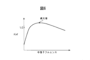
- FIG. 6 shows a graph for explaining the relationship between the neutron fluence of the fuel and the infinite neutron multiplication factor in the present embodiment.
- the horizontal axis represents the neutron fluence obtained by integrating the neutron flux with time, and the vertical axis represents the infinite neutron multiplication factor kinf.
- the neutron fluence is an amount corresponding to the burnup of the fuel, for example.
- deteriorated uranium is used as fuel.
- Depleted uranium includes, for example, about 99.8% uranium 238 and about 0.2% uranium 235.
- Uranium 238 transmutates as shown in the following equation 1 by absorbing neutrons. Uranium 238 is converted to plutonium 239.
- uranium 238 absorbs neutrons to generate plutonium 239, thereby increasing the infinite neutron multiplication factor.
- the ratio of the abundance of plutonium 239 and the like to the abundance of uranium 238 approaches a constant value, and fission products (FP) accumulate, and the infinite neutron multiplication factor gradually decreases.
- the fuel in the present embodiment has a characteristic that the infinite neutron multiplication factor increases at the initial stage of combustion, and then the infinite neutron multiplication factor gradually decreases.
- the size of the core is selected so as to satisfy such conditions, and the fuel assemblies and fuel rods are designed.
- CANDLE combustion can be carried out by adopting the core configuration as described above. That is, it is possible to form a core in which power is generated over the entire radial direction of the core and a combustion part is generated in a partial region in the axial direction of the core.
- Fig. 7 shows a graph of the infinite neutron multiplication factor when burning at an infinite core height.
- the horizontal axis represents the core height
- the vertical axis represents the infinite neutron multiplication factor of the fuel.
- the combustion section moves toward the new fuel section.
- the combustion part includes a region where the infinite neutron multiplication factor exceeds 1.
- the actual reactor core height is finite, and in this case, the infinite neutron multiplication factor at the end of the reactor core may slightly deviate from the graph shown in FIG.
- FIG. 8 shows a graph for explaining the state of combustion of the core in this embodiment and the fuel replacement.
- FIG. 8 shows an initial and final graph of the nth cycle core and an initial and final graph of the (n + 1) th cycle core.
- the power density at the core axis, the number density of uranium 238, and the number density of fission products are shown.
- the maximum point of the power density moves toward the lower part of the core where the new fuel part 11 is arranged as indicated by an arrow 101.
- Combustion in the present embodiment moves in a direction from the upper end to the lower end of the core.
- the speed at which the combustion section moves that is, the speed at which the maximum point of the power density moves is, for example, several centimeters per year.
- the combustion part moves slowly.
- the number density of uranium 238 becomes smaller on the downstream side of the combustion section by transmutation.
- the number density of fission products increases on the downstream side of the combustion section due to the occurrence of fission.
- the combustion ends when the combustion part reaches almost the lower end of the core.
- FIG. 9 shows a schematic partial cross-sectional view of the core in the present embodiment.
- the core 10 in the present embodiment is disposed inside the baffle plate 34.
- the fuel assembly 21 is arranged so that the longitudinal direction is substantially parallel to the axial direction of the core 10.
- Reactor 1 in the present embodiment includes a reactivity application mechanism to which a reactivity capable of changing the output of core 10 is applied when the temperature of the coolant flowing in the core changes.
- An assembly lower end support member 32 is disposed at the lower end portion of the core 10.
- the lower end of the fuel assembly 21 is fixed to the assembly lower end support member 32. Since the assembly lower end support member 32 only needs to fix the fuel assembly 21, an excellent material can be used as a structural material.
- An assembly upper end support member 33 is disposed at the upper end portion of the core 10. The assembly upper end support member 33 is formed so as to movably support the upper end of the fuel assembly 21. The upper end of the fuel assembly 21 is supported by the assembly upper end support member 33 so as to be movable outward.
- the core 10 in the present embodiment includes an interval adjusting plate 31 as an interval adjusting member that supports a plurality of fuel assemblies 21 to each other.
- the interval adjusting plate 31 is disposed in the portion of the support lattice 25a among the plurality of support lattices 25a and 25b (see FIG. 3). In a portion where the interval adjusting plate 31 is not disposed, a gap is formed between the support lattices 25b of the fuel assemblies 21 adjacent to each other.
- FIG. 10 shows a schematic plan view of the interval adjusting plate in the present embodiment.
- the interval adjusting plate 31 has a hole 31 a into which the fuel assembly 21 is inserted.
- the hole 31 a of the interval adjusting plate 31 is formed so as to fit into the support grid 25 a of the fuel assembly 21.
- the interval adjusting plate 31 in the present embodiment is formed so as to support all the fuel assemblies 21 included in the core 10. By arranging the support grid 25a of the fuel assembly 21 in the hole 31a, the adjacent fuel assemblies 21 can be restrained from each other. An interval between the plurality of fuel assemblies 21 is determined.
- the interval adjusting plate 31 in the present embodiment is formed of a material that expands when the temperature rises.
- the interval adjusting plate 31 is made of a material having a large coefficient of thermal expansion.
- the interval adjusting plate 31 in the present embodiment is formed of a material having a larger coefficient of thermal expansion than the aggregate lower end support member 32.
- An example of a material having a large coefficient of thermal expansion is stainless steel.
- stainless steel SUS304 (based on Japanese Industrial Standard (JIS)) containing 8 to 10.5% nickel and 18 to 20% chromium, or 10 to 14% nickel, 16 to 18% chromium, and 2 molybdenum Stainless steel SUS316 containing 3% (based on Japanese Industrial Standards (JIS)) can be employed.
- FIG. 9 shows the axial power density and coolant temperature in addition to the schematic diagram of the core.
- the solid line indicates the initial (BOC) state of the operating cycle, and the broken line indicates the end (EOC) state of the operating cycle.
- the distribution of the power density and the distribution of the coolant temperature move toward the lower end of the core as indicated by an arrow 101 from the beginning to the end of the operation cycle.
- the temperature of the coolant rises from the lower end of the core 10 toward the upper end.
- the interval adjusting plate 31 in the present embodiment is arranged in the region of the combustion part at the beginning of the operation cycle. In particular, in the present embodiment, it is arranged in the region of the combustion part throughout the operation cycle. In other words, the interval adjusting plate 31 is disposed inside the region of the combustion section both in the initial and final stages of the operation cycle. The interval adjusting plate 31 is arranged in a region where the temperature of the coolant increases during the operation cycle.
- the interval adjusting plate 31 in the present embodiment is disposed at a position where the power density is substantially maximized at the initial stage of the operation cycle in the axial direction of the core.
- the interval adjusting plate 31 in the present embodiment is disposed at a position where the temperature rise of the coolant in the direction from the core inlet to the core outlet becomes moderate at the initial stage of the operation cycle.
- FIG. 11 shows another schematic partial cross-sectional view of the core in the present embodiment.
- the coolant contacts the interval adjusting plate 31.
- interval adjustment board 31 also rises with the temperature rise of a coolant.
- the gap adjusting plate 31 expands outward in the radial direction as indicated by an arrow 120.
- the fuel assembly 21 is restrained by the interval adjusting plate 31.
- the lower end of the fuel assembly 21 is fixed to the assembly lower end support member 32.
- the interval adjusting plate 31 expands, as shown by an arrow 121, the upper end of the fuel assembly 21 is directed outward in the radial direction.
- the effective neutron multiplication factor of the core 10 can be made less than 1, and the reactivity applied to the core 10 can be made negative. That is, in the core 10 in the present embodiment, a negative reactivity is applied when the temperature of the coolant rises.
- the core 10 in this Embodiment can make the temperature coefficient regarding a coolant negative.
- the temperature coefficient of fuel easily becomes negative due to the Doppler effect, but its absolute value is small.
- the temperature coefficient related to the coolant in the present embodiment can be a negative value having a large absolute value.
- the temperature coefficient related to the coolant of the present embodiment can be a negative value much larger than the temperature coefficient of the fuel. For this reason, even if the temperature coefficient of other structural materials or the like is positive, the temperature coefficient of the entire core can be easily made negative.
- the core in the present embodiment changes the shape of the core to reduce the temperature coefficient related to the coolant, the temperature coefficient related to the coolant is negative even in a large core having a large number of fuel assemblies. Can be.
- the interval adjusting plate 31 in the present embodiment is disposed in a region included in the combustion portion at the initial stage of the operation cycle.
- the interval adjusting plate 31 can be arranged in a region where the temperature change range of the coolant is large. The amount of expansion can be increased.
- swells can be enlarged, and the temperature coefficient regarding a coolant can be made into a more negative value.
- the interval adjusting plate 31 when the interval adjusting plate 31 is arranged in the vicinity of the lower end of the core 10, the interval adjusting plate 31 is arranged outside the combustion portion at the initial stage of the operation cycle. In the vicinity of the lower end of the core 10, since the heat generated by nuclear fission is not transferred to the coolant, the temperature change width of the coolant is reduced. For this reason, the space
- the interval adjusting plate 31 by arranging the interval adjusting plate 31 in the region of the combustion part, the interval adjusting plate 31 can be arranged in an area where the temperature of the coolant is relatively high. In this region, since the temperature change width of the coolant is increased, the interval adjusting plate 31 can be greatly expanded. The temperature coefficient for the coolant can be made more negative.
- the temperature change width of the coolant is increased, so that the speed of changing the volume of the interval adjusting plate 31 is increased.
- the interval between the fuel assemblies 21 can be increased or decreased. That is, the response speed of the reactivity with respect to the temperature change of the coolant can be improved.
- the interval adjusting plate 31 in the present embodiment is disposed at a position in the axial direction of the core where the coolant temperature becomes a value close to the coolant temperature at the core outlet at the initial stage of the operation cycle.
- the coolant temperature rises greatly from the core inlet toward the core outlet mainly in the region where the power density of the combustion section is high.
- the core includes a high increase rate region 131 in which the temperature of the coolant rises from the core inlet toward the core exit, and a low increase rate region in which the rate of temperature increase is smaller than that in the high increase rate region 131. 132.
- the low increase rate region 132 is disposed downstream of the high increase rate region 131.
- FIG. 9 shows a high increase rate region 131 and a low increase rate region 132 in the initial stage of the operation cycle.
- the interval adjusting plate 31 in the present embodiment is disposed in the low increase rate region 132 where the temperature rise of the coolant is moderate at the beginning of the operation cycle.
- the interval adjusting plate 31 can be disposed in the low increase rate region 132 from the beginning to the end of the operation cycle. Even if the combustion section moves during the operation cycle, the coolant temperature in the interval adjusting plate 31 does not change so much and the expansion amount does not change. For this reason, the change of the effective neutron multiplication factor accompanying fuel combustion can be suppressed, and ideal CANDLE combustion can be implement
- the interval adjusting plate 31 is disposed at a position close to the assembly lower end support member 32 in which the interval between the fuel assemblies 21 remains unchanged in a range where the coolant temperature is close to the coolant temperature at the core outlet. Is preferred. In the present embodiment, it is preferable to arrange at a position close to the core inlet.
- the interval adjusting plate 31 is preferably disposed at the end of the low increase rate region 132 on the core inlet side at the beginning of the operation cycle. With this configuration, when the interval adjusting plate 31 expands, the interval between the fuel assemblies can be increased, and the temperature coefficient related to the coolant can be set to a more negative value.
- interval adjustment plate 31 is not restricted to this form, For example, you may arrange
- the temperature of the coolant flowing in the core increases, and when the power of the core decreases, the temperature of the coolant flowing in the core decreases.
- the coolant travels in the flow path in the core from the core inlet toward the core outlet.
- the coolant receives heat from the fuel body as it travels through the flow path.
- the variation range of the coolant temperature is the smallest at the core inlet and the largest at the core outlet.
- the change range of the coolant temperature becomes smaller when the output is changed, and the coolant temperature is lower than that of the low change region.
- a high change region 134 in which the change width becomes large can be determined.
- the low change area 133 in the present embodiment is an area arranged on the upstream side of the high change area 134.
- the interval adjusting member By disposing the interval adjusting member in the high change region 134, the amount of deformation of the interval adjusting member when the power of the core changes can be increased. Further, when the position of the lower end of the fuel body is fixed, the amount of movement of the upper end of the fuel body can be increased by arranging the interval adjusting member in the low change region 133. That is, even if the amount of deformation of the gap adjusting member is small, the distance between the lower end of the fuel bodies and the gap adjusting member is small, so that the amount of change in the gap between the fuel bodies can be increased.
- the lower end of the fuel assembly is fixed by the assembly lower end support member, but the present invention is not limited to this configuration, and the lower end of the fuel assembly has a diameter similar to the upper end of the fuel assembly. It may be supported so as to be movable in the direction.
- the assembly lower end support member may be formed so as to thermally expand in accordance with the temperature of the coolant.
- the assembly lower end support member disposed at the lower end of the fuel assembly may be formed of the same material as the interval adjustment member.
- the fuel body whose interval is adjusted by the interval adjusting member includes the fuel assembly, but is not limited to this form, and a fuel rod may be adopted as the fuel body.
- the fuel assembly in which the fuel rods are bundled may not be configured, and the fuel rods may be directly supported by the interval adjusting member so as to ensure a coolant flow path.
- the interval adjusting member in the present embodiment is formed so as to support all the fuel bodies among the plurality of fuel bodies included in the reactor core, but is not limited to this embodiment, and some fuel bodies are used. You may form so that it may support.
- interval adjustment member in this Embodiment contains the space
- the interval adjusting member may include a member such as a wire formed in a linear shape.
- the gap adjusting member may be a massive member that is thermally expanded and attached to the fuel assembly.
- the interval adjusting member includes a rectangular parallelepiped member attached to the outer surface of the support grid so that the rectangular parallelepiped members of adjacent fuel assemblies come into contact with each other when the fuel assemblies are loaded on the core. Can be formed.
- the interval adjusting plate is disposed at one position in the axial direction of the core, but the present invention is not limited to this configuration, and interval adjusting members may be disposed at a plurality of positions. .
- the output of the core 10 is adjusted by controlling the temperature of the coolant flowing in the core in accordance with the change in the power required for the core 10.
- Reactor 1 in the present embodiment can apply a reactivity having a large absolute value when the temperature of the coolant flowing in core 10 changes.
- Reactor 1 in the present embodiment adjusts the output of the core by performing coolant temperature adjustment control that changes the temperature of the coolant flowing into core 10.
- the temperature coefficient related to the coolant has a negative value with a large absolute value. For this reason, by raising the temperature of the coolant flowing into the core 10, a negative reactivity having a large absolute value can be applied to the core 10, and the output of the core 10 can be reduced.
- a large positive reactivity can be applied to the core 10, and the output of the core 10 can be increased.
- not only fine adjustment for changing the core power by about several percent, but rough adjustment for changing the core power by several tens of percent, for example, can be performed.
- control in order to change the temperature of the coolant flowing into the core 10, control is performed to change the load of the apparatus connected to the nuclear reactor.
- the power generation facility in the present embodiment performs control to change the generated power.
- the generated power is reduced to reduce the load.
- the opening degree of the flow rate adjusting valve 44 By reducing the opening degree of the flow rate adjusting valve 44, the flow rate of steam supplied to the turbine 4 is reduced and the generated power is reduced.
- the amount of heat exchanged in the steam generator 3 is reduced.
- the temperature of the secondary sodium 52 circulating through the intermediate heat exchanger 2 and the steam generator 3 rises.
- the temperature of the primary sodium 51 (coolant) flowing out from the intermediate heat exchanger 2 also rises.
- the temperature of the coolant flowing into the core 10 rises, and the temperature of the coolant flowing inside the core 10 rises.
- the temperature of the coolant is higher at the core outlet than at the core inlet, but the average temperature of the coolant in the core increases.
- the average coolant temperature can be exemplified by the average coolant temperature in the direction of the core axis. Since the core 10 has a negative temperature coefficient related to the coolant, a negative reactivity is applied to the core 10 when the temperature of the coolant rises. As a result, the output of the core 10 can be reduced.
- the generated power is increased in order to increase the load.
- the opening degree of the flow rate adjustment valve 44 By increasing the opening degree of the flow rate adjustment valve 44, the flow rate of steam supplied to the turbine 4 increases, and the generated power increases.
- the amount of heat for heat exchange in the steam generator 3 increases. For this reason, the temperature of the secondary sodium 52 and the primary sodium 51 (coolant) decreases.
- the temperature of the coolant flowing into the core 10 is lowered, and a positive reactivity is applied to the core 10. As a result, the output of the core 10 can be increased.
- the temperature of the coolant flowing into the core 10 can be increased, and the output of the core 10 can be increased. Can be reduced. Further, by increasing the amount of heat consumed by the device connected to the nuclear reactor 1, the temperature of the coolant flowing into the core 10 can be reduced, and the output of the core 10 can be increased.
- the nuclear reactor in this embodiment can change the output of the core without using control rods.
- a nuclear reactor it is not restricted to this form, You may use the reactivity adjustment by a control rod together.
- the temperature of the coolant flowing into the reactor core is changed by adjusting the flow rate of the steam supplied to the turbine.
- Any device that can be adjusted can be employed.
- at least one of a circulation channel for primary sodium 51, a circulation channel for secondary sodium 52, and a circulation channel for water and water vapor is used as a heat exchanger. Etc. may be arranged to adjust the temperature of the heat medium.
- FIG. 12 shows a time chart of the coolant temperature adjustment control in the present embodiment.
- FIG. 12 illustrates control for reducing the output of the core.
- the nuclear reactor in the present embodiment is operated so that the output of the core is substantially constant in normal operation control.
- FIG. 12 shows a case where the coolant temperature at the core inlet is increased stepwise by a solid line. Until time t1, steady operation is performed. Further, the flow rate of the coolant flowing into the core is kept substantially constant during the period of changing the power output of the core.
- control is performed to reduce the generated power.
- the coolant temperature at the core inlet rises stepwise.
- the fuel temperature and the coolant temperature at the core outlet increase as the coolant temperature at the core inlet increases.
- the fuel temperature gradually rises from the core inlet toward the core outlet as the coolant temperature rises.
- the fuel temperature shown in FIG. 12 indicates the average temperature in the core 10.
- a value obtained by averaging the fuel temperature in the direction of the core axis can be exemplified as in the average temperature of the coolant.
- the average temperature of the coolant in the core also rises.
- the temperature coefficient related to the coolant since the temperature coefficient related to the coolant has a negative value having a large absolute value, a negative reactivity is applied to the core. For this reason, the state where the criticality is maintained is changed to the subcritical state, and the output of the core is lowered.
- FIG. 12 shows a case where the coolant temperature at the core inlet is gradually increased by a broken line.
- the generated power can be gradually decreased.
- the output of the core can be gradually decreased.
- the reactivity applied to the core continues to be almost constant at zero. That is, the power of the core can be changed while the core is maintained in a substantially critical state.
- the fuel temperature and the coolant temperature at the core outlet also change gradually without changing rapidly.
- the coolant temperature adjustment control for changing the coolant temperature flowing into the core can be changed stepwise or gradually.
- the coolant temperature at the core inlet can be lowered stepwise or gradually, contrary to the above control example.
- the reactivity application mechanism of the present embodiment is formed such that the temperature adjustment factor for the coolant becomes a negative value having a large absolute value when the interval adjusting member expands or contracts due to the temperature change of the coolant. ing.
- the reactivity application mechanism is not limited to this form, and any mechanism to which reactivity capable of changing the output of the core can be applied.
- the reactivity application mechanism preferably employs a coolant mainly composed of 208 Pb of lead isotopes in order to make the temperature coefficient related to the coolant a negative value having a larger absolute value.
- Lead is suitable as a fast reactor coolant because it has a large fast neutron scattering cross section and a small capture cross section.
- Lead has four isotopes of lead 204, lead 206, lead 207, and lead 208.
- lead 208 has a smaller neutron capture cross section than other lead isotopes, and is therefore suitable as a coolant.
- lead 208 can have a more negative temperature coefficient for the coolant than other lead isotopes.
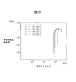
- FIG. 13 shows a graph of the inelastic scattering cross section of the lead isotope.
- the horizontal axis and the vertical axis are shown on a logarithmic scale.
- the inelastic scattering cross section of each lead isotope has a predetermined threshold. For example, lead 204 and lead 206 have a threshold when the neutron energy is about 10 6 eV. If it is larger than this threshold, the neutron is inelastically scattered and decelerated.
- the neutron spectrum of the fast reactor has a peak at a neutron energy slightly lower than 10 6 eV.
- a neutron energy slightly lower than 10 6 eV For example, when lead 204 and lead 206 are used as the coolant, many neutrons are inelastically scattered by the coolant and decelerated. For this reason, when the coolant temperature rises and the coolant density decreases, the effect of slowing down the inelastic neutron scattering becomes very small. The neutron spectrum hardens and the reactivity changes to the positive side.
- the effect of inelastically scattering neutrons is smaller than that of lead 204 and the like because the neutron energy threshold of the inelastic scattering cross section is large. For this reason, even if the temperature of the coolant rises and the density of the coolant decreases, the effect of hardening the neutron spectrum can be made smaller than that of lead 204 or the like. The action of the reactivity shifting to the positive side can be made smaller than that of lead 204 or the like. For this reason, when lead 208 is used as the coolant, the temperature coefficient related to the coolant can be set to a more negative value than when other lead 204 or the like is used as the coolant.
- the coolant it is preferable to employ a coolant mainly composed of lead 208 in which the content of lead 208 is increased by isotopic separation of lead or the like. Furthermore, it is preferable that almost all of the lead contained in the coolant is lead 208. With this configuration, the temperature coefficient related to the coolant can be set to a negative value having a larger absolute value. Further, the output of the core can be easily changed.
- the fuel in the present embodiment has been described by taking deteriorated uranium as an example of new fuel loaded in the core, but is not limited to this form, and at least one of natural uranium and deteriorated uranium is used to achieve CANDLE combustion. be able to.
- the present invention can be applied to any fast neutron reactor capable of performing CANDLE combustion.
- the combustion part of the previous cycle is arranged above the new fuel part at the beginning of the operation cycle, but the present invention is not limited to this form, and the new fuel part is one of the combustion parts in the axial direction of the core. It can be arranged at either end. Furthermore, new fuel portions may be disposed on both sides of the combustion portion.
- the portion that starts the initial combustion of the operation cycle uses the fuel disposed in the lower part of the core at the end of the operation cycle of the previous cycle.
- the portion that starts combustion at the early stage of the operation cycle may be formed so as to spontaneously generate neutrons.
- a fuel containing a predetermined concentration of plutonium, enriched uranium, or the like may be disposed.
- combustion may be started by supplying neutrons from the outside.
- the core in the present embodiment has the core axial direction parallel to the vertical direction, but is not limited to this form, and the core axial direction may be parallel to the horizontal direction. That is, the core in the present embodiment may be placed horizontally.
- the core of a nuclear reactor used for power generation equipment has been described as an example.
- the present invention is not limited to this embodiment, and the present invention can be applied to a nuclear reactor of any equipment.
- the nuclear reactor of the present invention can be used as a power source for ships and the like.
- the reactor and power generation equipment in the second embodiment will be described.
- the structures of the nuclear reactor and power generation equipment in the present embodiment are the same as those in the first embodiment.
- the coolant flow rate adjustment control for changing the flow rate of the coolant flowing into the core is performed, thereby changing the reactivity applied to the core and changing the output of the core.
- control is performed to change the temperature of the coolant flowing in the core in accordance with the change in power required for the core.
- the temperature of the coolant flowing in the core is changed by changing the flow rate of the coolant flowing into the core.
- the temperature of the coolant at the core outlet can be changed by changing the flow rate of the coolant flowing into the core 10.
- the average temperature of the coolant in the core 10 changes.
- the average value of the coolant temperature changes in the axial direction of the core from the core inlet to the core outlet.
- a positive or negative reactivity can be applied to the core 10.
- the coolant temperature in the core 10 can be increased by reducing the flow rate of the coolant flowing into the core 10. Since the core of the nuclear reactor in the present embodiment has a temperature coefficient related to a negative coolant having a large absolute value, by increasing the coolant temperature in the core 10, negative reactivity with respect to the core 10 is increased. Can be applied. As a result, the output of the core 10 can be reduced. Further, by increasing the flow rate of the coolant flowing into the core 10, a positive reactivity can be applied to the core 10, and the output of the core 10 can be increased.
- the flow rate of the coolant flowing into the core 10 is changed by changing the output of the pump 41 that supplies the coolant to the core 10.
- the load connected to the nuclear reactor is set so that the temperature of the coolant flowing into the core 10 becomes substantially constant. It is adjusting. That is, the generated power is adjusted.
- FIG. 14 shows a time chart of coolant flow rate adjustment control in the present embodiment.
- FIG. 14 illustrates control for reducing the output of the core.
- FIG. 14 shows a case where the flow rate of the coolant flowing into the core is changed in a step shape by a solid line. Until time t1, steady operation is performed.
- the flow rate of the coolant flowing into the core 10 is decreased stepwise.
- the coolant temperature at the core outlet temporarily rises because the flow rate of the coolant flowing through the core 10 decreases.
- the average temperature of the coolant in the core will also rise.
- the fuel temperature temporarily increases as the average temperature of the coolant increases.
- the fuel temperature shown in FIG. 14 indicates an average temperature in the core.
- the temperature coefficient related to the coolant is a negative value having a large absolute value
- a negative reactivity is applied to the core 10 and the output of the core 10 is reduced.
- the coolant temperature and fuel temperature at the core outlet decrease, and become substantially constant.
- the reactivity shifts to the positive side as the coolant temperature in the core decreases and the fuel temperature decreases, and returns to almost zero. That is, the core temporarily becomes subcritical and then returns to the critical state.
- the output of the core decreases from time t1 and becomes substantially constant at a predetermined output.
- the reactor core in the present embodiment can reduce the output of the core by reducing the flow rate of the coolant supplied to the core.
- FIG. 14 shows a case where the coolant flow rate is gradually changed by a broken line.
- the flow rate of the coolant is gradually changed, the reactivity of the core is kept at a substantially zero value.
- the power of the core can be reduced while the core is maintained in a substantially critical state.
- the coolant temperature and fuel temperature at the core outlet also change gradually. Thus, even if the flow rate of the coolant flowing into the core is gradually changed, the output of the core can be changed.
- the flow rate of the coolant flowing into the core can be increased stepwise or gradually, contrary to the above control example.
- the flow rate of the coolant flowing into the core is changed by changing the output of the pump that supplies the coolant to the core.
- the flow rate of the coolant flowing in can be changed.
- a device for adjusting the flow rate of the coolant may be disposed inside the reactor vessel, or a device for adjusting the flow rate of the coolant may be disposed at the end of the fuel assembly.
- the coolant temperature adjustment control of the first embodiment and the coolant flow rate adjustment control of the second embodiment can be performed in combination.
- the coolant flow rate adjustment control can be performed as the auxiliary control during the period when the output of the core is changed using the coolant flow rate adjustment control as the main control.
Landscapes
- Physics & Mathematics (AREA)
- Engineering & Computer Science (AREA)
- Plasma & Fusion (AREA)
- General Engineering & Computer Science (AREA)
- High Energy & Nuclear Physics (AREA)
- Chemical & Material Sciences (AREA)
- Chemical Kinetics & Catalysis (AREA)
- Monitoring And Testing Of Nuclear Reactors (AREA)
Abstract
L'invention concerne un réacteur nucléaire doté d'un cœur de réacteur, le cœur du réacteur comportant une section de combustible neuf qui contient de l'uranium et une section de combustion dans laquelle le combustible est brûlé, et le cœur du réacteur pouvant générer une puissance de sortie lorsqu'il se produit une division nucléaire de plutonium et se déplaçant dans la direction où se déplace la section de combustion vers la section de combustible neuf au cours de la période comprise entre l'étape initiale et l'étape de fin du cycle d'exploitation. Le réacteur nucléaire est également équipé d'un mécanisme d'insertion de réactivité capable d'insérer une réactivité susceptible de faire varier la puissance de sortie issue du cœur du réacteur lorsque la température d'un matériau de refroidissement qui circule dans le cœur du réacteur est modifiée, et le mécanisme d'insertion de réactivité réalise une régulation telle que la température du matériau de refroidissement qui circule dans le cœur du réacteur puisse être modifiée en fonction de la variation de puissance de sortie requise du cœur du réacteur.
Priority Applications (3)
| Application Number | Priority Date | Filing Date | Title |
|---|---|---|---|
| CN201280006257.7A CN103329210B (zh) | 2011-02-10 | 2012-01-18 | 原子炉和发电设备 |
| EP12745136.7A EP2674948A4 (fr) | 2011-02-10 | 2012-01-18 | Réacteur nucléaire et installation de génération d'électricité |
| US13/984,776 US9543045B2 (en) | 2011-02-10 | 2012-01-18 | Nuclear reactor and power generation facility |
Applications Claiming Priority (4)
| Application Number | Priority Date | Filing Date | Title |
|---|---|---|---|
| JP2011-027483 | 2011-02-10 | ||
| JP2011027483A JP2012167953A (ja) | 2011-02-10 | 2011-02-10 | 原子炉の炉心および原子炉 |
| JP2011-030850 | 2011-02-16 | ||
| JP2011030850A JP5717091B2 (ja) | 2011-02-16 | 2011-02-16 | 原子炉を備える設備 |
Publications (1)
| Publication Number | Publication Date |
|---|---|
| WO2012108238A1 true WO2012108238A1 (fr) | 2012-08-16 |
Family
ID=46638457
Family Applications (1)
| Application Number | Title | Priority Date | Filing Date |
|---|---|---|---|
| PCT/JP2012/050972 Ceased WO2012108238A1 (fr) | 2011-02-10 | 2012-01-18 | Réacteur nucléaire et installation de génération d'électricité |
Country Status (4)
| Country | Link |
|---|---|
| US (1) | US9543045B2 (fr) |
| EP (1) | EP2674948A4 (fr) |
| CN (1) | CN103329210B (fr) |
| WO (1) | WO2012108238A1 (fr) |
Families Citing this family (5)
| Publication number | Priority date | Publication date | Assignee | Title |
|---|---|---|---|---|
| ITUA20163714A1 (it) * | 2016-05-04 | 2017-11-04 | Luciano Cinotti | Reattore nucleare, con elementi di combustibile muniti di espansori |
| RU2655161C1 (ru) * | 2017-06-02 | 2018-05-24 | Акционерное общество Инжиниринговая компания "АСЭ" | Одноконтурная атомная электростанция с теплоносителем под давлением |
| CN109872825A (zh) * | 2019-03-21 | 2019-06-11 | 路春雷 | 反应堆 |
| RU2733900C1 (ru) * | 2020-03-06 | 2020-10-08 | Государственная корпорация по атомной энергии "Росатом" | Быстрый жидко-солевой реактор |
| CN111508620B (zh) * | 2020-04-30 | 2023-03-24 | 中国核动力研究设计院 | 一种反应堆机动性自调节方法 |
Citations (4)
| Publication number | Priority date | Publication date | Assignee | Title |
|---|---|---|---|---|
| JPH01101497A (ja) * | 1987-10-15 | 1989-04-19 | Nippon Atom Ind Group Co Ltd | 固有安全原子炉 |
| JPH0743488A (ja) * | 1993-07-30 | 1995-02-14 | Hitachi Ltd | 原子炉の炉心支持構造 |
| JP2002071866A (ja) * | 2000-08-30 | 2002-03-12 | Tokyo Inst Of Technol | 原子炉の炉心およびその炉心における核燃料物質の取替方法 |
| JP2007232429A (ja) * | 2006-02-28 | 2007-09-13 | Tokyo Institute Of Technology | 原子炉の運転方法 |
Family Cites Families (9)
| Publication number | Priority date | Publication date | Assignee | Title |
|---|---|---|---|---|
| US3600276A (en) * | 1968-10-07 | 1971-08-17 | John B Nims Jr | Fuel systems for nuclear reactors |
| US4255236A (en) * | 1977-11-01 | 1981-03-10 | Robbins Thomas R | Reactor and fuel assembly design for improved fuel utilization in liquid moderated thermal reactors |
| GB8707614D0 (en) * | 1987-03-31 | 1987-05-07 | Nat Nuclear Corp Ltd | Reactivity control in nuclear reactors |
| US20080123797A1 (en) * | 2006-11-28 | 2008-05-29 | Searete Llc, A Limited Liability Corporation Of The State Of Delaware | Automated nuclear power reactor for long-term operation |
| US8942338B2 (en) * | 2009-04-06 | 2015-01-27 | TerraPower, LLC. | Traveling wave nuclear fission reactor, fuel assembly, and method of controlling burnup therein |
| US8320513B2 (en) * | 2009-04-16 | 2012-11-27 | The Invention Science Fund I, Llc | Nuclear fission reactor, flow control assembly, methods therefor and a flow control assembly system |
| US9704604B2 (en) * | 2009-04-16 | 2017-07-11 | Terrapower, Llc | Nuclear fission reactor fuel assembly and system configured for controlled removal of a volatile fission product and heat released by a burn wave in a traveling wave nuclear fission reactor and method for same |
| EP2461329A4 (fr) * | 2009-07-31 | 2014-03-19 | Tokyo Inst Tech | C ur de réacteur d'un réacteur nucléaire et réacteur nucléaire |
| US9793013B2 (en) * | 2009-11-06 | 2017-10-17 | Terrapower, Llc | Systems and methods for controlling reactivity in a nuclear fission reactor |
-
2012
- 2012-01-18 US US13/984,776 patent/US9543045B2/en not_active Expired - Fee Related
- 2012-01-18 CN CN201280006257.7A patent/CN103329210B/zh not_active Expired - Fee Related
- 2012-01-18 EP EP12745136.7A patent/EP2674948A4/fr not_active Withdrawn
- 2012-01-18 WO PCT/JP2012/050972 patent/WO2012108238A1/fr not_active Ceased
Patent Citations (5)
| Publication number | Priority date | Publication date | Assignee | Title |
|---|---|---|---|---|
| JPH01101497A (ja) * | 1987-10-15 | 1989-04-19 | Nippon Atom Ind Group Co Ltd | 固有安全原子炉 |
| JPH0743488A (ja) * | 1993-07-30 | 1995-02-14 | Hitachi Ltd | 原子炉の炉心支持構造 |
| JP2002071866A (ja) * | 2000-08-30 | 2002-03-12 | Tokyo Inst Of Technol | 原子炉の炉心およびその炉心における核燃料物質の取替方法 |
| JP3463100B2 (ja) | 2000-08-30 | 2003-11-05 | 東京工業大学長 | 原子炉の炉心における核燃料物質の取替方法 |
| JP2007232429A (ja) * | 2006-02-28 | 2007-09-13 | Tokyo Institute Of Technology | 原子炉の運転方法 |
Non-Patent Citations (1)
| Title |
|---|
| See also references of EP2674948A4 * |
Also Published As
| Publication number | Publication date |
|---|---|
| CN103329210A (zh) | 2013-09-25 |
| CN103329210B (zh) | 2016-08-31 |
| US20130322588A1 (en) | 2013-12-05 |
| EP2674948A1 (fr) | 2013-12-18 |
| US9543045B2 (en) | 2017-01-10 |
| EP2674948A4 (fr) | 2017-11-22 |
Similar Documents
| Publication | Publication Date | Title |
|---|---|---|
| EP2589049B1 (fr) | Composition de combustible nucléaire au disiliciure de triuranium pour utilisation dans des réacteurs à eau légère | |
| KR102605338B1 (ko) | 도플러 반응도 증대 장치 | |
| US20100040187A1 (en) | Heat pipe nuclear fission deflagration wave reactor cooling | |
| Sato et al. | GTHTR300—A nuclear power plant design with 50% generating efficiency | |
| WO2012108238A1 (fr) | Réacteur nucléaire et installation de génération d'électricité | |
| JP5807868B2 (ja) | 原子炉 | |
| JP5716920B2 (ja) | 原子炉の炉心および原子炉 | |
| JP6726596B2 (ja) | 燃料集合体及びそれを装荷する沸騰水型原子炉の炉心 | |
| JP5717091B2 (ja) | 原子炉を備える設備 | |
| Grudzinski et al. | Design and analysis of the core restraint system for a small modular fast reactor | |
| JP2012167953A (ja) | 原子炉の炉心および原子炉 | |
| JP2012145552A (ja) | 原子炉の炉心および原子炉 | |
| RU2601558C1 (ru) | Способ эксплуатации ядерного реактора в топливном цикле с расширенным воспроизводством делящихся изотопов | |
| US9159459B2 (en) | Heat pipe nuclear fission deflagration wave reactor cooling | |
| JP5502267B2 (ja) | 原子炉の運転方法 | |
| Sekimoto et al. | A Design and Safety Features of Small CANDLE Fast Reactor | |
| JP2006300849A (ja) | 増殖炉になり得る高転換比のabwr炉心 |
Legal Events
| Date | Code | Title | Description |
|---|---|---|---|
| 121 | Ep: the epo has been informed by wipo that ep was designated in this application |
Ref document number: 12745136 Country of ref document: EP Kind code of ref document: A1 |
|
| WWE | Wipo information: entry into national phase |
Ref document number: 2012745136 Country of ref document: EP |
|
| WWE | Wipo information: entry into national phase |
Ref document number: 13984776 Country of ref document: US |
|
| NENP | Non-entry into the national phase |
Ref country code: DE |