WO2012108486A1 - 投射型表示装置 - Google Patents
投射型表示装置 Download PDFInfo
- Publication number
- WO2012108486A1 WO2012108486A1 PCT/JP2012/052923 JP2012052923W WO2012108486A1 WO 2012108486 A1 WO2012108486 A1 WO 2012108486A1 JP 2012052923 W JP2012052923 W JP 2012052923W WO 2012108486 A1 WO2012108486 A1 WO 2012108486A1
- Authority
- WO
- WIPO (PCT)
- Prior art keywords
- light
- projection
- emitting element
- display device
- light emitting
- Prior art date
- Legal status (The legal status is an assumption and is not a legal conclusion. Google has not performed a legal analysis and makes no representation as to the accuracy of the status listed.)
- Ceased
Links
Images



Classifications
-
- G—PHYSICS
- G02—OPTICS
- G02B—OPTICAL ELEMENTS, SYSTEMS OR APPARATUS
- G02B27/00—Optical systems or apparatus not provided for by any of the groups G02B1/00 - G02B26/00, G02B30/00
- G02B27/10—Beam splitting or combining systems
- G02B27/1006—Beam splitting or combining systems for splitting or combining different wavelengths
- G02B27/102—Beam splitting or combining systems for splitting or combining different wavelengths for generating a colour image from monochromatic image signal sources
- G02B27/1026—Beam splitting or combining systems for splitting or combining different wavelengths for generating a colour image from monochromatic image signal sources for use with reflective spatial light modulators
-
- G—PHYSICS
- G03—PHOTOGRAPHY; CINEMATOGRAPHY; ANALOGOUS TECHNIQUES USING WAVES OTHER THAN OPTICAL WAVES; ELECTROGRAPHY; HOLOGRAPHY
- G03B—APPARATUS OR ARRANGEMENTS FOR TAKING PHOTOGRAPHS OR FOR PROJECTING OR VIEWING THEM; APPARATUS OR ARRANGEMENTS EMPLOYING ANALOGOUS TECHNIQUES USING WAVES OTHER THAN OPTICAL WAVES; ACCESSORIES THEREFOR
- G03B21/00—Projectors or projection-type viewers; Accessories therefor
- G03B21/14—Details
-
- G—PHYSICS
- G03—PHOTOGRAPHY; CINEMATOGRAPHY; ANALOGOUS TECHNIQUES USING WAVES OTHER THAN OPTICAL WAVES; ELECTROGRAPHY; HOLOGRAPHY
- G03B—APPARATUS OR ARRANGEMENTS FOR TAKING PHOTOGRAPHS OR FOR PROJECTING OR VIEWING THEM; APPARATUS OR ARRANGEMENTS EMPLOYING ANALOGOUS TECHNIQUES USING WAVES OTHER THAN OPTICAL WAVES; ACCESSORIES THEREFOR
- G03B21/00—Projectors or projection-type viewers; Accessories therefor
- G03B21/14—Details
- G03B21/142—Adjusting of projection optics
-
- G—PHYSICS
- G03—PHOTOGRAPHY; CINEMATOGRAPHY; ANALOGOUS TECHNIQUES USING WAVES OTHER THAN OPTICAL WAVES; ELECTROGRAPHY; HOLOGRAPHY
- G03B—APPARATUS OR ARRANGEMENTS FOR TAKING PHOTOGRAPHS OR FOR PROJECTING OR VIEWING THEM; APPARATUS OR ARRANGEMENTS EMPLOYING ANALOGOUS TECHNIQUES USING WAVES OTHER THAN OPTICAL WAVES; ACCESSORIES THEREFOR
- G03B21/00—Projectors or projection-type viewers; Accessories therefor
- G03B21/14—Details
- G03B21/26—Projecting separately subsidiary matter simultaneously with main image
-
- G—PHYSICS
- G03—PHOTOGRAPHY; CINEMATOGRAPHY; ANALOGOUS TECHNIQUES USING WAVES OTHER THAN OPTICAL WAVES; ELECTROGRAPHY; HOLOGRAPHY
- G03B—APPARATUS OR ARRANGEMENTS FOR TAKING PHOTOGRAPHS OR FOR PROJECTING OR VIEWING THEM; APPARATUS OR ARRANGEMENTS EMPLOYING ANALOGOUS TECHNIQUES USING WAVES OTHER THAN OPTICAL WAVES; ACCESSORIES THEREFOR
- G03B35/00—Stereoscopic photography
- G03B35/16—Stereoscopic photography by sequential viewing
-
- H—ELECTRICITY
- H04—ELECTRIC COMMUNICATION TECHNIQUE
- H04N—PICTORIAL COMMUNICATION, e.g. TELEVISION
- H04N9/00—Details of colour television systems
- H04N9/12—Picture reproducers
- H04N9/31—Projection devices for colour picture display, e.g. using electronic spatial light modulators [ESLM]
- H04N9/3141—Constructional details thereof
- H04N9/315—Modulator illumination systems
- H04N9/3164—Modulator illumination systems using multiple light sources
Definitions
- the present invention relates to a projection display device capable of displaying a three-dimensional image.
- Projection type display devices are also called projectors, and are classified into liquid crystal projectors, DLP (Digital Light Processing; registered trademark, hereinafter omitted) projectors, LCOS (Liquid Crystal On Silicon Silicon) projectors, and the like.
- DLP Digital Light Processing; registered trademark, hereinafter omitted
- LCOS Liquid Crystal On Silicon Silicon
- the DLP projector displays an image using a reflective mirror array element represented by DMD (Digital Micromirror Device; registered trademark, hereinafter omitted), and an internal total reflection prism in which two prisms are arranged to face each other. (TIR [Total Internal Reflection] prism) is used (see, for example, Patent Document 1).
- DMD Digital Micromirror Device
- TIR Total Internal Reflection
- the image display device in order to visually recognize a three-dimensional moving image or still image using active shutter glasses, the timing for switching the signals of the left-eye and right-eye images by the frame sequential method. And the timing of opening / closing the active shutter of the left eye and the right eye of the glasses must be synchronized.
- the image display device is a device that directly displays an image on the display panel, infrared communication, wireless communication in another frequency band, or wired communication can be used for this synchronization.
- a technique for automatically adjusting the focus of a projection lens by projecting detection projection light and detecting light reflected from a screen is known (see, for example, Patent Document 2).
- a transmissive panel composed of LCD (Liquid Crystal Display) for light modulation with three primary colors and a prism (or mirror) that synthesizes light emitted from the LCD for each color are combined.
- a semitransparent reflective film means is disposed between the prism (or mirror) and the projection lens, and detection projection from a light emitting unit provided separately from the LCD The light output is projected to the screen side through the projection lens, and the reflected light from the screen is also detected through the semitransparent reflection film means and the projection lens, and used to adjust the focus.
- the opening and closing of the active shutter can be controlled by communication means regardless of wireless or wired.
- the apparatus main body is provided with an infrared transmission unit having an infrared light emitting element, and infrared rays are projected from the infrared transmission unit onto a screen on which an image is projected, and the reflected infrared rays are reflected there. It is preferable to use it for synchronization.
- the reason for using reflection in this way is that the projection display device is premised on the viewer viewing the screen image, so that infrared rays are emitted from the screen and the light-receiving part of the glasses is directed to the image side. And the most efficient and convenient, and the cost is lower than installing a separate transmitter near the screen.
- FIG. 10 is a schematic diagram showing a configuration in which an infrared transmission unit is provided in order to stereoscopically view an image using active shutter glasses in a projection display device according to the prior art.
- a projection display device (3D projector) 100 capable of displaying a three-dimensional image shown in FIG. 10 includes a light source device 10 and a color wheel that time-divides light emitted from the light source device 10 into three colors of red, green, and blue. 11 and a condenser lens having a plurality of lenses for condensing the light emitted from the rod integrator 12 and the rod integrator 12 that emits light through the color wheel 11 to be totally reflected and emitted in a uniform illuminance distribution.
- the TIR prism 15 reflects the emitted light from the condenser lens 13 at the internal reflection surface (boundary surface) 15 c and makes it incident on the DMD 14.
- the TIR prism 15 is configured such that the light reflected by the DMD 14 is transmitted through the internal reflection surface 15 c and emitted to the projection lens 16.
- the video projected from the projection lens 16 can be viewed with the 3D glasses G having an active shutter, but as described above, it is necessary to synchronize the opening and closing of the right and left eye active shutters with the video. Therefore, the main body of the 3D projector 100 is provided with an infrared light emitting element separately from the projection optical system.
- the 3D projector 100 is provided with a lens shift function. Therefore, as shown in the drawing, three infrared light emitting elements 101 C , 101 L , and 101 R are arranged separately from the projection optical system.
- Infrared light emitting element 101 C is an element corresponding to the image position for disposed under normal that when not in lens shift, the infrared image S iC is projected to a portion of the image S is thereby on the screen
- the infrared light emitting element 101 L is an element arranged corresponding to the image position when the lens is shifted to the left side, and thereby, a part of the image S L (the right end of the image S L is not shown). An infrared image S iL is projected.
- Infrared light emitting element 101 R is an element which is arranged corresponding to an image position when the lens shift to the right, thereby image S R (Note that the left edge of the image S R is not shown) to the part of the An infrared image S iR is projected.
- the glasses G receive one infrared image emitted from any one according to the position of the shift by the light receiving unit, and based on the infrared intensity (change), that is, based on the infrared pulse, Controls opening and closing of the shutter.
- the infrared transmission unit in order to synchronize the 3D image and the active shutter glasses to allow the viewer to stereoscopically view the image, the infrared transmission unit must be mounted on the main body of the projection display device. Such a problem arises. Of course, even if ultraviolet rays or visible rays are used instead of infrared rays, basically the same problem occurs. (1) The infrared transmitter is attached to the side surface of the apparatus main body, and there are restrictions on the internal layout and design. (2) Since reflection from the screen is used, delicate settings such as matching the directivity of infrared rays to the screen side are required.
- the present invention has been made in view of the above situation, and an object of the present invention is to provide a light emitting element such as an infrared light emitting element in the main body of the projection display apparatus in a projection display apparatus capable of displaying a three-dimensional image.
- a light emitting element such as an infrared light emitting element in the main body of the projection display apparatus in a projection display apparatus capable of displaying a three-dimensional image.
- lens shift and zoom without increasing the number of light-emitting elements and the output, and without providing additional components.
- a first technical means of the present invention includes an internal total reflection prism in which two prisms are arranged to face each other and a projection lens, and transmits light emitted from a light source to the internal total reflection prism.
- a projection-type display device that can display a three-dimensional image projected from the projection lens via the projection lens, further comprising a light-emitting element, and the light-emitting element makes a light beam incident on the internal total reflection prism. It is arranged so as to be reflected by the internal reflection surface of the internal total reflection prism and projected through the projection lens.
- the light emitting element has an incident surface of light emitted from the light source and an output surface to the projection lens with respect to the internal total reflection prism.
- the light beam is arranged so as to be incident from a different surface.
- the projection display device further includes a reflective mirror array element, and emits light emitted from a light source to the reflective mirror array element and the entire internal mirror. Projection is performed from the projection lens via a reflecting prism.
- the light emitting element reflects the incident surface of light emitted from the light source with respect to the internal total reflection prism, the reflection type mirror array element.
- the light beam is disposed so as to be incident from a surface different from the incident surface of the incident light and the exit surface to the projection lens.
- the light-emitting element is a light-emitting diode.
- the light emitting element is a laser element.
- the light emitting element has a half-value angle corresponding to an effective capture angle indicated by an F value of the projection lens. It is what.
- the light beam projected from the projection lens and reflected by the projection surface is used for viewing an active shutter type three-dimensional image. It is used for opening and closing an active shutter in glasses.
- the light emitting element is an infrared light emitting element or an ultraviolet light emitting element
- the internal total reflection prism includes the internal reflection surface. This is characterized in that an antireflection film for visible light is provided.
- a light emitting element such as an infrared light emitting element
- the number of light emitting elements and output are not increased. It is possible to cope with lens shift and zoom without providing additional components.
- FIG. 6 is a schematic view showing a configuration in which an infrared transmission unit is provided in order to stereoscopically view an image using active shutter glasses in a projection display device according to a conventional technique.
- the projection display device is characterized in that a light emitting element is provided in the main body.
- a light emitting element is provided in the main body.
- an infrared light emitting element that emits infrared light that is invisible light is basically used as such a light emitting element.
- a light-emitting element is not limited to infrared light, and may be an element that emits ultraviolet light, which is another example of invisible light, or an element that emits visible light. Any element that emits light in a band different from the spectrum of the projected light projected as an image from the above can be similarly applied.
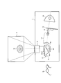
- FIG. 1 is a schematic view showing a configuration example of a projection display device according to the present invention.
- reference numeral 1 denotes a projection display device (hereinafter simply referred to as “3D projector”) corresponding to a three-dimensional image display according to the present invention.
- S is an image projected on the screen
- G is 3D-compatible glasses.
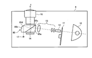
- the 3D projector 1 includes a light source device 10, a color wheel 11, a rod integrator 12, a condenser lens 13, a reflective mirror array element (hereinafter referred to as DMD) 14 represented by DMD, a TIR prism 15, and a projection lens 16.
- DMD reflective mirror array element
- This is a device that projects light emitted from the device 10 from the projection lens 16 via the DMD 14 and the TIR prism 15.
- the 3D projector 1 can display a 3D image by projection in addition to a normal two-dimensional image.
- the light source device 10 may be configured to have a high-intensity lamp such as a metal halide lamp or an ultra-high pressure mercury lamp.
- the color wheel 11 includes filters for the three primary colors of red, green, and blue, and is configured so that they rotate at high speed, whereby the light emitted from the light source device 10 is converted into three colors of red, green, and blue. To divide.
- the color wheel 11 may be configured to include a colorless and transparent portion or a yellow filter in order to increase luminance.
- the rod integrator 12 and the condenser lens 13 are disposed between the light source device 10 and the DMD 14.
- the rod integrator 12 receives light through the color wheel 11, totally reflects the light, and emits the light with a uniform illuminance distribution.
- the condenser lens 13 is a lens group that collects the light emitted from the rod integrator 12 and emits it to the TIR prism 15.
- the DMD 14 is a display element in which a number of micro mirror surfaces (micro mirrors) corresponding to the number of pixels are arranged in a plane.
- the DMD 14 receives light reflected by an internal reflection surface (boundary surface) 15c of a TIR prism 15 described later, and is not shown.
- an image is formed by reflected light and returned to the TIR prism 15.
- the DMD 14 can return the color image to the TIR prism 15 by reflecting the image of each color with the red, green, and blue sequential signals synchronized with the high-speed rotation of the color wheel 11.
- the TIR prism 15 has two triangular prisms 15a and 15b arranged to face each other, and allows only light incident at an angle smaller than a predetermined incident angle to pass through its internal reflection surface (boundary surface) 15c. It is designed to reflect.
- the internal reflection surface 15c is provided at a portion where the oblique sides of the two triangular prisms 15a and 15b are combined.
- a layer having a low refractive index may be formed by, for example, an air layer.
- a spacer formed by vacuum-depositing a metal or dielectric on the opposing surface may be provided to form a finely spaced air layer, or the entire circumference of the peripheral edge on the opposing surface of one triangular prism
- An air layer may be formed by providing a convex portion on a portion other than the periphery as a concave portion.
- the critical angle can be determined by the ratio of the refractive index of the low refractive index layer thus formed and the triangular prisms 15a and 15b.
- the TIR prism 15 reflects the light emitted from the condenser lens 13 by the internal reflection surface 15c and makes it incident on the DMD 14.
- the light reflected by the DMD 14 is incident and transmitted through the internal reflection surface 15c. It arrange
- the projection lens 16 is a lens that receives the light emitted from the TIR prism 15 and projects it onto the screen.
- the image projected from the projection lens 16 onto the screen is a red, green, and blue image that is sequentially reflected by the DMD 14 at a high speed, resulting in a color image.
- the 3D projector 1 is provided with an infrared light emitting element 17.
- the infrared light emitting element 17 is arranged as a part of the projection optical system as shown in FIG. More specifically, the infrared light emitting element 17 is disposed so that infrared light is incident on the TIR prism 15, reflected by the internal reflection surface 15 c of the TIR prism 15, and projected through the projection lens 16.
- the infrared light emitting element 17 is disposed so that infrared light is incident on the TIR prism 15, reflected by the internal reflection surface 15 c of the TIR prism 15, and projected through the projection lens 16.
- the infrared rays and the light from the light source can follow the optical path as described here (preferably the optical path as shown in FIG. 1). What is necessary is just to determine the critical angle etc. in the internal reflective surface 15c.
- the infrared image S i is also projected onto a part of the image S on the screen.
- the infrared image may be, for example, an image in which only the center portion of the screen is a circle as shown in the figure, or an image having a rectangular shape.
- an image of another shape may be adopted. It doesn't matter how big it is.
- the image (moving image or still image) projected from the projection lens 16 is a 3D image
- the viewer can view it with the 3D glasses G of the active shutter system.
- the infrared signal emitted from the infrared light emitting element 17 and reflected on the screen is used to open and close the active shutter in the 3D glasses G.
- a frame sequential method that alternately displays left-eye video and right-eye video every time is used, and active shutter-type glasses are used as dedicated glasses, and a 3D projector.
- the active shutter for the left eye of the glasses is opened, the active shutter for the right eye is closed and only the left eye of the glasses is opened, and the 3D projector 1 displays the image for the right eye.
- only the right eye of the glasses needs to be opened during the output period.
- the infrared light output from the infrared light emitting element 17 may be stored as a pulse signal that matches the frame for the left eye and the frame for the right eye.
- infrared light may be output so that an ON signal is generated for a left eye frame and an OFF signal is generated for a right eye frame.
- the 3D glasses G may receive infrared rays reflected from the screen, determine ON / OFF of the pulse signal based on the intensity of the received infrared rays, and control the opening / closing of the left and right active shutters based on the determination result. .
- Infrared light output from the infrared light emitting element 17 is projected onto the screen from the TIR prism 15 through the projection lens 16 in the same way as the path of the 3D image in this way, so that it can cope with lens shift and zoom.
- the 3D projector 1 uses the TIR prism 15 originally arranged for the purpose of separating the illumination light and the imaging light and achieving the image display function in the DMD 3D projector. Since it is configured without additional parts, the above-mentioned problems (1) to (9) can be solved. That is, since the 3D projector 1 uses the original projection lens 16 and the TIR prism 15, the internal layout and appearance design are not affected. Further, in the 3D projector 1, since it is output from the projection lens 16, it always coincides with the place where the image is projected, and when the zoom lens is provided with the zoom lens wide side, tele side, and lens shift function Stable 3D glasses can be expected regardless of the lens shift position. Further, in the 3D projector 1, since infrared light efficiently reaches a narrow range on the screen, it is possible to reduce the output or the number of infrared light emitting elements 17 as compared with the conventional case.
- the lens shift and zoom can be handled without increasing the number and output of the infrared light emitting elements 17 and without providing additional components. Can do.
- the DLP projector using the TIR prism 15 originally receives infrared light from the surface not used for image projection and reflects it on the internal reflection surface 15c. Is projected onto the screen by a projection lens 16 for displaying a projected image.
- the infrared light emitting element 17 is different from the TIR prism 15 from the incident surface of the light emitted from the light source device 10, the incident surface of the light reflected by the DMD 14, and the exit surface to the projection lens 16. From the above, the infrared rays are disposed. In the present invention, as described above, infrared rays are reflected by the internal reflection surface 15c. Therefore, in this configuration example, the infrared light incident on the TIR prism 15 is reflected on the inner side of the emission surface to the projection lens 16, then reflected by the internal reflection surface 15 c and emitted from the emission surface to the projection lens 16. It becomes like this.
- Such a configuration example is preferable because the infrared light emitting element 17 is not in a position where it interferes with image input.
- the infrared light emitting element 17 may be disposed so as to be incident from another surface such as the exit surface to the projection lens 16, but the TIR prism 15 is made larger than the structural example shown in FIG. There is a need for some cost.
- the optical system using the TIR prism 15 as shown in FIG. 1 is basically required when providing a lens shift function in a projector using DMD. Of course, it is necessary to provide a moving mechanism for lens shift. This will be described with reference to FIGS.
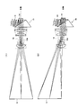
- FIG. 2 is a diagram for explaining lens shift using a TIR prism
- FIGS. 2A and 2B are views showing the optical path before the lens shift and the optical path after the lens shift, respectively.
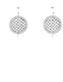
- 3A and 3B are schematic views showing the positional relationship between the diaphragm and the illumination light in the states shown in FIGS. 2A and 2B, respectively.
- FIG. 2A and 2B show respective optical paths when the projection lens 16 is arranged at the A position (normal position) and the B position by lens shift using a TIR prism.
- the positions of the illumination optical system such as the condenser lens 13, the DMD 14, and the TIR prism 15 are fixed to the main body of the 3D projector 1.
- the position of the projection image 16 can be changed by sliding the position of the projection lens 16 in the direction perpendicular to the optical axis by the moving mechanism (the same applies to the position of the infrared image).
- the DMD 14 side of the projection lens 16 is telecentric, while the illumination light is also designed in advance to be telecentric after being reflected by the DMD 14 in order to efficiently enter the projection lens 16. It is. Even if the projection lens 16 is moved in this state, the principal ray (in this case, parallel to the optical axis) always passes through the center of the stop 16d, so that the ray is not blocked in the middle.
- the illumination light L is in the cross section D of the diaphragm at both the A position and the B position. It is inside and can transmit light efficiently.
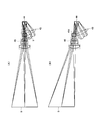
- FIGS. 4A and 4B are diagrams for explaining the lens shift when the TIR prism is not used.
- FIGS. 4A and 4B are views showing the optical path before the lens shift and the optical path after the lens shift, respectively.
- 5A and 5B are schematic views showing the positional relationship between the diaphragm and the illumination light in the states shown in FIGS. 4A and 4B, respectively.
- FIG. 4A and 4B show respective optical paths when the projection lens 46 is arranged at the A position and the B position (normal position) by lens shift without using the TIR prism.
- the stop 46d of the projection lens 46 is designed to be close to the lens closest to the DMD 44, and the illumination system is designed in advance so as to collect light with respect to the stop 46d. Accordingly, the illumination light and the lens of the illumination optical system can be established without interference, that is, without interference of light rays or components.
- a convex lens or a concave mirror having a positive power
- the position of the projection lens 46 is moved in the direction perpendicular to the optical axis by the moving mechanism while the positions of the illumination optical system such as the condenser lens 43 and the DMD 44 are fixed to the 3D projector main body.
- the projection image 46 is moved to the position A as shown in FIG. 4A when the position of the projection image S is changed by sliding, the illumination light or the lens (concave mirror) of the illumination optical system is moved. Since it is fixed, it interferes as shown by the area I and does not hold.
- the reflected light from the DMD 44 is fixed to the illumination system and the DMD 44, and thus becomes a broken line in FIG. 46d) cannot be passed efficiently.
- the illumination light L is in the cross section D of the stop at the B position. At the position, the illumination light L is outside the cross section D of the diaphragm, and the light cannot pass therethrough.
- an optical system using a TIR prism may be used, and an optical system using a TIR prism is necessarily employed.
- FIG. 6 is a diagram showing an example of frequency characteristics of an antireflection film provided on the internal reflection surface of the TIR prism of FIG.
- the visible light returns to the DMD 14 side as can be seen by tracing the light ray backward from the screen in FIG.
- an ordinary antireflection film for visible light is applied on the internal reflection surface 15c by coating or the like, the film thickness and the number of layers are reduced so as to reduce the reflectance in the visible light band (wavelength of about 400 nm to 700 nm). Only the design is performed, and the intended design is not performed for the other bands. More specifically, as shown in the graph 61 of FIG. 6, the infrared frequency is reflected as shown in the graph 61 of FIG.
- the optical system described with reference to FIG. 1 can be established only by adding an antireflection film for visible light.
- the TIR prism 15 is preferably provided with an antireflection film for visible light on the internal reflection surface 15c. Thereby, while functioning as a reflection film for infrared rays, reflection of visible light can be substantially prevented when the angle is smaller than a predetermined incident angle.
- the antireflection film applied to the internal reflection surface 15c in this way functions as a reflection film for the emitted infrared light, but is configured to increase the reflectance for the emitted infrared light, that is, It is preferable that the film has a performance that increases the reflectance with respect to the emitted infrared light. More specifically, the antireflection film is designed so that the film has a reflectivity frequency characteristic in which the reflectivity for infrared rays (here, a wavelength of 900 nm is assumed) is increased as shown by a graph 62 in FIG. May be configured.
- the transmittance of the projection lens 16 with respect to the infrared ray becomes important.
- the transmittance of the normal antireflection film for visible light is lowered and is not usable.
- the transmittance of the projection lens 16 can be easily increased by designing the film in consideration of infrared rays (in particular, having the characteristics as shown in the graph 62) in the same manner as the internal reflection surface 15c. it can.
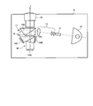
- the projection display device according to the present invention is not limited to the configuration provided with the TIR prism 15 as shown in FIG. 1, and for example, configuration examples as shown in FIG. 7 and FIG. 7 and 8 are schematic views showing other configuration examples of the projection type display device according to the present invention.
- 7 and 8 are 3D projectors.
- the 3D projectors 7 and 8 and the 3D projector 1 of FIG. 1 will be basically described.
- the 3D projector 7 has a TIR prism 70.
- a triangular prism 75a similar to the triangular prism 15a of the TIR prism 15 in FIG. 1 and a triangular prism 75b are disposed to face each other, and an internal reflection surface (boundary surface) 75c thereof is the same as the internal reflection surface 15c. Only light incident at an angle smaller than a predetermined incident angle is allowed to pass, and the rest is totally reflected.
- the 3D projector 7 differs from the 3D projector 1 shown in FIG.
- An infrared light emitting element 17 is provided on the exit surface side of the TIR prism 70 to the projection lens 16 so that infrared light is incident from the surface of the TIR prism 70. Therefore, the incident infrared rays are irradiated to the surface 75d other than the exit surface to the projection lens 16 and the internal reflection surface 75c. Therefore, the surface 75d is provided with a total reflection coating or an infrared reflection coating so as to function as an infrared reflection surface that reflects infrared rays.
- the 3D projector 8 has a TIR prism 80.
- a triangular prism 85a similar to the triangular prism 15a of the TIR prism 15 in FIG. 1 and a modified triangular prism 85b are arranged to face each other, and an internal reflection surface (boundary surface) 85c thereof is the internal reflection surface 15c.
- an internal reflection surface (boundary surface) 85c thereof is the internal reflection surface 15c.
- the 3D projector 8 is different from the 3D projector 1 in FIG. 1 in the incident position of the infrared light emitting element 17.
- the triangular prism 85 b is provided with a surface parallel to the incident surface from the DMD 14 in the triangular prism 85 a, and infrared light is incident from the surface by the infrared light emitting element 17 provided on the surface side.
- the triangular prism 85b is provided with an inclined surface 85d that is provided with an infrared reflection coating and functions as an infrared reflection surface so that incident infrared rays do not escape to the exit surface side to the projection lens 16.
- the inclined surface 85d is formed at an angle such that the infrared light reflected by the inclined surface 85d is reflected by the internal reflecting surface 85c and directed toward the projection lens 16.
- FIG. 9 is a schematic view showing another configuration example of the projection display device according to the present invention, in which 9 is a 3D projector.
- the 3D projector 9 is an apparatus that includes three DMDs, a DMD 14 G for green, a DMD 14 R for red, and a DMD 14 B for blue, and a Philips dichroic prism 90 that is a three-color separation / combination prism. Similar to the 3D projector 1 of FIG. 1, the 3D projector 9 is configured such that infrared light emitted from the infrared light emitting element 17 enters from a surface of the TIR prism 15 that is not used for video.
- the 3D projector 9 divides incident light into R, G, and B by a dichroic prism 90, and controls each DMD 14 G , 14 R , and 14 B by a control unit (not shown), thereby reflecting an image of each color and dichroic prism.
- the image is recombined at 90 and emitted to the screen side via the TIR prism 15 and the projection lens 16. Therefore, unlike the 3D projector 1 in FIG. 1, the 3D projector 9 does not need to be provided with the color wheel 11. Other parts of the 3D projector 9 that are the same as those of the 3D projector 1 are not described.
- the internal reflection surface of the TIR prism in the case of emitting ultraviolet rays from the light emitting element.
- ultraviolet rays are reflected as shown in the graph 61 of FIG. 6 in which the frequency characteristic of the reflectance is illustrated for the glass with a normal visible light antireflection film. That is, in the configuration example of FIG. 1, the optical system as described with reference to FIG. 1 can be established only by adding a normal visible light antireflection film on the internal reflection surface 15c.
- the antireflection film applied to the internal reflection surface 15c functions as a reflection film for the emitted ultraviolet rays, but is configured to increase the reflectivity for the emitted ultraviolet rays. In other words, it is preferable that the film has a performance to increase the reflectance with respect to the emitted ultraviolet light.
- the antireflection film applied to the internal reflection surface 15c functions as a reflection film for the visible light emitted from the light emitting element, that is, only the wavelength band of the visible light emitted from the light emitting element. It is necessary to configure so as to employ an antireflection film that reflects. In such a configuration, there is a concern that light in that wavelength band in the image will not be projected on the screen S, but the wavelength band is kept extremely narrow (and visible light in a band with low frequency of use is used). By causing the light emitting element to emit light), the influence on the image can be reduced.
- light transmission such as infrared transmission in the present invention has been described on the premise that it is used for opening and closing an active shutter in active shutter glasses, but focus adjustment at the time of zooming in the projection lens 16, etc.
- the infrared ray or the like is used, or the infrared ray transmission or the like in the present invention is not used for opening / closing the active shutter, but only for other purposes such as focus adjustment. You can also.
- the infrared light emitting element 17 a light emitting diode can be adopted.
- the infrared light emitting element 17 may be a laser element. Since the numerical aperture (NA) of the laser element is extremely small, there is no influence of the opening of the projection lens 16 and it is possible to project efficiently.
- NA numerical aperture
- a light emitting diode or laser element can be adopted as the light emitting element.
- the half value angle of the infrared light emitting element 17 will be described.
- the projection type display apparatus has been described with reference to an apparatus that displays an image using a reflective mirror array element.
- an apparatus employing another optical method that does not use a mirror array element such as a liquid crystal projector. Even so, the same function can be achieved by adding the internal total reflection prism and adopting the arrangement of the light emitting elements as described above.
- a projection display device that does not use a mirror array element includes an internal total reflection prism in which two prisms are arranged to face each other and a projection lens, and projects light emitted from a light source from the projection lens through the internal total reflection prism. This is a device capable of displaying a three-dimensional image.
- a liquid crystal projector is taken as an example of a configuration not using a mirror array element, and will be described with reference to the configuration example of FIG. 1.
- the DMD 14 is removed, for example, a liquid crystal display from the surface of the TIR prism 15 where the DMD 14 is disposed. What is necessary is just to arrange
- the DMD 14 is removed from the configuration example of FIG. 1, a liquid crystal display element is provided in front of the TIR prism 15 (for example, between the condenser lens 13 and the TIR prism 15), and the surface shown on the DMD 14 side of the TIR prism 15 is totally reflected. You may do it.
- the light emitting element emits infrared rays from a surface different from the incident surface of the light emitted from the light source (the light source that has passed through the liquid crystal) and the exit surface to the projection lens 16 with respect to the TIR prism 15. It is preferable to arrange so that the light rays such as. However, light rays such as infrared rays may be incident from the exit surface to the projection lens 16 as in the configuration example of FIG.
- 1,7,8,9 ... 3D projector 10 ... light source device, 11 ... color wheel, 12 ... rod integrator 13 ... condenser lens, 14 ... DMD, 14 B ... DMD blue, 14 G ... green DMD, 14 R ... DMD for red, 15, 70, 80 ... TIR prism, 15a, 15b, 75a, 75b, 85a, 85b ... Triangular prism, 15c, 75c, 85c ... Internal reflection surface (boundary surface), 16 ... Projection lens, 17 Infrared light emitting element, 43 ... condenser lens, 44 ... DMD, 46 ... projection lens, 61, 62 ... characteristic graph, 75d ... surface, 85d ... slope, 90 ... dichroic prism.
Landscapes
- Physics & Mathematics (AREA)
- General Physics & Mathematics (AREA)
- Optics & Photonics (AREA)
- Engineering & Computer Science (AREA)
- Multimedia (AREA)
- Signal Processing (AREA)
- Projection Apparatus (AREA)
- Transforming Electric Information Into Light Information (AREA)
- Testing, Inspecting, Measuring Of Stereoscopic Televisions And Televisions (AREA)
- Stereoscopic And Panoramic Photography (AREA)
- Lenses (AREA)
Abstract
Description
しかしながら、画像表示装置が投射型である場合には、赤外線発光素子を有する赤外線送信部を装置本体に備えるようにし、映像を投射するスクリーンに赤外線送信部から赤外線を投射し、そこで反射した赤外線を用いて同期をとることが好ましい。このように反射を用いる理由としては、投射型表示装置では、視聴者がスクリーンの映像を鑑賞するのが前提であるため、スクリーン内から赤外線を発すると共にメガネの受光部を映像側に向けておくと最も効率的で利便性も高いこと、並びに、別付けの送信器をスクリーン近傍に設置するよりも低コストで済むことなどが挙げられる。
(1)赤外線送信部は装置本体の側面などに取り付けることになり、内部レイアウトやデザインに制限がある。
(2)スクリーンからの反射を利用するため、赤外線の指向性をスクリーン側に合わせるなど微妙な設定が必要となる。
(5)投射型表示装置にレンズシフト機能をもたせる場合は、投影画像とスクリーンの位置関係が調節可能なため、より広い方向に赤外線を向ける必要があるが、一方で高感度を保つために指向性をある程度保つ必要がある。そのためには、図10において3箇所の赤外線発光素子101L,101C,101Rで示したように、レンズシフトに対応する画像位置に投射できるような配置で、別途赤外線発光素子を設ける必要がある。
(6)赤外光出力が必要の無い一般的な光学系と比べて、プリズムやミラーなど半透明反射膜手段やそれを保持するための補助的な部品も含め、追加部品が必要となり、コストや装置サイズが上がってしまう。
(7)同じく上記追加部品を挿入する空間を確保するためにLCDのパネルから投射レンズまでの距離、すなわちバックフォーカスが長くなる。これにより、投射レンズ設計においてより強い正のパワーと負のパワーを必要とすることになるため、レンズ枚数が増加し、コストや装置サイズが上がってしまう。
(9)共通プラットフォームを使って3D対応と3D非対応の投射型表示装置を製造する場合、3D非対応の装置にも上記追加部品やレンズ枚数の多い投射レンズが必要となり余分なコストを背負うことになる。
Claims (9)
- 2つのプリズムが対向配置された内部全反射プリズムと、投射レンズとを備え、光源から発せられた光を前記内部全反射プリズムを介して前記投射レンズから投射する、3次元画像が表示可能な投射型表示装置であって、
発光素子をさらに備え、該発光素子は、前記内部全反射プリズムに光線を入射し、該光線を前記内部全反射プリズムの内部反射面で反射させ前記投射レンズを介して投射させるように、配置することを特徴とする投射型表示装置。 - 前記発光素子は、前記内部全反射プリズムに対して、前記光源から発せられた光の入射面、及び前記投射レンズへの出射面、とは異なる面から、前記光線を入射するように配置することを特徴とする請求項1に記載の投射型表示装置。
- 前記投射型表示装置は、反射型ミラーアレイ素子をさらに備え、光源から発せられた光を前記反射型ミラーアレイ素子及び前記内部全反射プリズムを介して前記投射レンズから投射することを特徴とする請求項1に記載の投射型表示装置。
- 前記発光素子は、前記内部全反射プリズムに対して、前記光源から発せられた光の入射面、前記反射型ミラーアレイ素子で反射された光の入射面、及び前記投射レンズへの出射面、とは異なる面から、前記光線を入射するように配置することを特徴とする請求項3に記載の投射型表示装置。
- 前記発光素子は、発光ダイオードであることを特徴とする請求項1~4のいずれか1項に記載の投射型表示装置。
- 前記発光素子は、レーザー素子であることを特徴とする請求項1~4のいずれか1項に記載の投射型表示装置。
- 前記発光素子は、前記投射レンズのF値が示す有効取り込み角度に相当する半値角をもつことを特徴とする請求項1~6のいずれか1項に記載の投射型表示装置。
- 前記投射レンズから投射され、被投射面で反射した前記光線は、アクティブシャッタ方式の3次元画像視聴用メガネにおけるアクティブシャッタの開閉に用いられることを特徴とする請求項1~7のいずれか1項に記載の投射型表示装置。
- 前記発光素子は、赤外線発光素子又は紫外線発光素子であり、前記内部全反射プリズムは、前記内部反射面に可視光用の反射防止膜を設けたことを特徴とする請求項1~8のいずれか1項に記載の投射型表示装置。
Priority Applications (2)
| Application Number | Priority Date | Filing Date | Title |
|---|---|---|---|
| CN2012800020786A CN103003749A (zh) | 2011-02-10 | 2012-02-09 | 投影显示设备 |
| US13/807,634 US20130100413A1 (en) | 2011-02-10 | 2012-02-09 | Projection display device |
Applications Claiming Priority (4)
| Application Number | Priority Date | Filing Date | Title |
|---|---|---|---|
| JP2011-026690 | 2011-02-10 | ||
| JP2011026690 | 2011-02-10 | ||
| JP2012-024057 | 2012-02-07 | ||
| JP2012024057A JP5044723B2 (ja) | 2011-02-10 | 2012-02-07 | 投射型表示装置 |
Publications (1)
| Publication Number | Publication Date |
|---|---|
| WO2012108486A1 true WO2012108486A1 (ja) | 2012-08-16 |
Family
ID=46638698
Family Applications (1)
| Application Number | Title | Priority Date | Filing Date |
|---|---|---|---|
| PCT/JP2012/052923 Ceased WO2012108486A1 (ja) | 2011-02-10 | 2012-02-09 | 投射型表示装置 |
Country Status (4)
| Country | Link |
|---|---|
| US (1) | US20130100413A1 (ja) |
| JP (1) | JP5044723B2 (ja) |
| CN (1) | CN103003749A (ja) |
| WO (1) | WO2012108486A1 (ja) |
Cited By (1)
| Publication number | Priority date | Publication date | Assignee | Title |
|---|---|---|---|---|
| CN114967297A (zh) * | 2022-04-29 | 2022-08-30 | 歌尔光学科技有限公司 | 一种光学模组及其组装方法 |
Families Citing this family (5)
| Publication number | Priority date | Publication date | Assignee | Title |
|---|---|---|---|---|
| CN105093801A (zh) * | 2014-05-22 | 2015-11-25 | 上海华博信息服务有限公司 | 一种基于色彩分割的单机立体投影装置 |
| CN105527717B (zh) * | 2014-09-28 | 2021-03-30 | 深圳光峰科技股份有限公司 | 立体投影系统 |
| CN107561833B (zh) * | 2017-09-13 | 2020-08-18 | 明基智能科技(上海)有限公司 | 投影机 |
| US11057595B2 (en) * | 2019-02-08 | 2021-07-06 | Texas Instruments Incorporated | Projection on multiple planes using a single projection unit |
| US12177602B2 (en) * | 2021-02-23 | 2024-12-24 | Apple Inc. | Light-folded projector |
Citations (7)
| Publication number | Priority date | Publication date | Assignee | Title |
|---|---|---|---|---|
| JPH11119184A (ja) | 1997-10-20 | 1999-04-30 | Fujitsu General Ltd | 液晶プロジェクタ用自動焦点装置 |
| JP2000206451A (ja) * | 1999-01-18 | 2000-07-28 | Minolta Co Ltd | プロジェクタ用光学系 |
| JP2000206610A (ja) * | 1999-01-18 | 2000-07-28 | Minolta Co Ltd | プロジェクタ用光学系 |
| JP2006126501A (ja) * | 2004-10-28 | 2006-05-18 | Nippon Telegr & Teleph Corp <Ntt> | 多眼立体表示装置および方法 |
| JP2007520758A (ja) * | 2004-02-05 | 2007-07-26 | ヒューレット−パッカード デベロップメント カンパニー エル.ピー. | 光を混合するためのシステム及び方法 |
| JP2009020424A (ja) | 2007-07-13 | 2009-01-29 | Chinontec Kk | 内部全反射プリズムおよび投射型表示装置 |
| JP2010513981A (ja) * | 2006-12-18 | 2010-04-30 | トムソン ライセンシング | 色域画像映写機及び色域画像映写法 |
Family Cites Families (4)
| Publication number | Priority date | Publication date | Assignee | Title |
|---|---|---|---|---|
| JP4689948B2 (ja) * | 2003-06-23 | 2011-06-01 | Necディスプレイソリューションズ株式会社 | プロジェクタ |
| JP3788622B2 (ja) * | 2004-10-29 | 2006-06-21 | シャープ株式会社 | 光学インテグレータ、照明装置、及び投影型画像表示装置 |
| US7651227B2 (en) * | 2005-09-13 | 2010-01-26 | Texas Instruments Incorporated | Projection system and method including spatial light modulator and compact diffractive optics |
| EP2067073A1 (en) * | 2006-09-14 | 2009-06-10 | Philips Intellectual Property & Standards GmbH | Laser projector with alerting light |
-
2012
- 2012-02-07 JP JP2012024057A patent/JP5044723B2/ja active Active
- 2012-02-09 CN CN2012800020786A patent/CN103003749A/zh active Pending
- 2012-02-09 WO PCT/JP2012/052923 patent/WO2012108486A1/ja not_active Ceased
- 2012-02-09 US US13/807,634 patent/US20130100413A1/en not_active Abandoned
Patent Citations (7)
| Publication number | Priority date | Publication date | Assignee | Title |
|---|---|---|---|---|
| JPH11119184A (ja) | 1997-10-20 | 1999-04-30 | Fujitsu General Ltd | 液晶プロジェクタ用自動焦点装置 |
| JP2000206451A (ja) * | 1999-01-18 | 2000-07-28 | Minolta Co Ltd | プロジェクタ用光学系 |
| JP2000206610A (ja) * | 1999-01-18 | 2000-07-28 | Minolta Co Ltd | プロジェクタ用光学系 |
| JP2007520758A (ja) * | 2004-02-05 | 2007-07-26 | ヒューレット−パッカード デベロップメント カンパニー エル.ピー. | 光を混合するためのシステム及び方法 |
| JP2006126501A (ja) * | 2004-10-28 | 2006-05-18 | Nippon Telegr & Teleph Corp <Ntt> | 多眼立体表示装置および方法 |
| JP2010513981A (ja) * | 2006-12-18 | 2010-04-30 | トムソン ライセンシング | 色域画像映写機及び色域画像映写法 |
| JP2009020424A (ja) | 2007-07-13 | 2009-01-29 | Chinontec Kk | 内部全反射プリズムおよび投射型表示装置 |
Cited By (2)
| Publication number | Priority date | Publication date | Assignee | Title |
|---|---|---|---|---|
| CN114967297A (zh) * | 2022-04-29 | 2022-08-30 | 歌尔光学科技有限公司 | 一种光学模组及其组装方法 |
| CN114967297B (zh) * | 2022-04-29 | 2024-06-11 | 歌尔光学科技有限公司 | 一种光学模组及其组装方法 |
Also Published As
| Publication number | Publication date |
|---|---|
| CN103003749A (zh) | 2013-03-27 |
| JP2012181514A (ja) | 2012-09-20 |
| JP5044723B2 (ja) | 2012-10-10 |
| US20130100413A1 (en) | 2013-04-25 |
Similar Documents
| Publication | Publication Date | Title |
|---|---|---|
| JP3642267B2 (ja) | 照明光学系およびこれを備えたプロジェクタ | |
| TWI436150B (zh) | Projector with dual projection function and its external kit | |
| CN102770794B (zh) | 用于激光投影的照射系统 | |
| JP5044723B2 (ja) | 投射型表示装置 | |
| JP2009538448A (ja) | エタンデュ値が大きいディジタル映写システム | |
| JP3174811U (ja) | 反射式光学エンジン | |
| CN105319820B (zh) | 投影装置 | |
| JPWO2002101457A1 (ja) | 照明装置及び投射型映像表示装置 | |
| CN103852960A (zh) | 投影装置与聚光模组 | |
| US20130135590A1 (en) | Projection apparatus | |
| CN101616286B (zh) | 光学单元及投射型影像显示装置 | |
| US20140063466A1 (en) | Projection apparatus | |
| CN111837073B (zh) | 图像显示设备 | |
| TW201833653A (zh) | 投影系統 | |
| NL1029702C2 (nl) | Kleurenprisma en daarvan gebruikmakende beeldweergaveinrichting van het projectietype. | |
| US7204594B2 (en) | Projector | |
| KR20020037797A (ko) | 단판식 액정 프로젝터용 컬러 분리장치 | |
| TWI440958B (zh) | 立體投影光源系統 | |
| JP6319290B2 (ja) | 画像投写装置 | |
| JP7447890B2 (ja) | 投射型表示装置 | |
| JP2016161746A (ja) | 画像表示装置、プロジェクター及び透過型表示装置 | |
| JP2012189761A (ja) | プロジェクターおよび画像表示システム | |
| WO2008041363A1 (en) | Projector | |
| TWI444750B (zh) | 用於一投影裝置之色輪模組、投影裝置、以及切換顯示一立體影像或一平面影像之方法 | |
| JP2012222421A (ja) | 会議システム、会議システムの制御方法、及びプログラム |
Legal Events
| Date | Code | Title | Description |
|---|---|---|---|
| WWE | Wipo information: entry into national phase |
Ref document number: 201280002078.6 Country of ref document: CN |
|
| 121 | Ep: the epo has been informed by wipo that ep was designated in this application |
Ref document number: 12745285 Country of ref document: EP Kind code of ref document: A1 |
|
| WWE | Wipo information: entry into national phase |
Ref document number: 13807634 Country of ref document: US Ref document number: 10885/CHENP/2012 Country of ref document: IN |
|
| ENP | Entry into the national phase |
Ref document number: 2013109408 Country of ref document: RU Kind code of ref document: A |
|
| NENP | Non-entry into the national phase |
Ref country code: DE |
|
| REG | Reference to national code |
Ref country code: BR Ref legal event code: B01A Ref document number: 112013001835 Country of ref document: BR |