WO2012108667A2 - Système de haut-parleur - Google Patents
Système de haut-parleur Download PDFInfo
- Publication number
- WO2012108667A2 WO2012108667A2 PCT/KR2012/000887 KR2012000887W WO2012108667A2 WO 2012108667 A2 WO2012108667 A2 WO 2012108667A2 KR 2012000887 W KR2012000887 W KR 2012000887W WO 2012108667 A2 WO2012108667 A2 WO 2012108667A2
- Authority
- WO
- WIPO (PCT)
- Prior art keywords
- speaker
- case
- bass
- sound
- outer case
- Prior art date
- Legal status (The legal status is an assumption and is not a legal conclusion. Google has not performed a legal analysis and makes no representation as to the accuracy of the status listed.)
- Ceased
Links
Images

Classifications
-
- H—ELECTRICITY
- H04—ELECTRIC COMMUNICATION TECHNIQUE
- H04R—LOUDSPEAKERS, MICROPHONES, GRAMOPHONE PICK-UPS OR LIKE ACOUSTIC ELECTROMECHANICAL TRANSDUCERS; ELECTRIC HEARING AIDS; PUBLIC ADDRESS SYSTEMS
- H04R1/00—Details of transducers, loudspeakers or microphones
- H04R1/02—Casings; Cabinets ; Supports therefor; Mountings therein
-
- H—ELECTRICITY
- H04—ELECTRIC COMMUNICATION TECHNIQUE
- H04R—LOUDSPEAKERS, MICROPHONES, GRAMOPHONE PICK-UPS OR LIKE ACOUSTIC ELECTROMECHANICAL TRANSDUCERS; ELECTRIC HEARING AIDS; PUBLIC ADDRESS SYSTEMS
- H04R1/00—Details of transducers, loudspeakers or microphones
- H04R1/20—Arrangements for obtaining desired frequency or directional characteristics
- H04R1/22—Arrangements for obtaining desired frequency or directional characteristics for obtaining desired frequency characteristic only
- H04R1/28—Transducer mountings or enclosures modified by provision of mechanical or acoustic impedances, e.g. resonator, damping means
- H04R1/2807—Enclosures comprising vibrating or resonating arrangements
- H04R1/2811—Enclosures comprising vibrating or resonating arrangements for loudspeaker transducers
-
- H—ELECTRICITY
- H04—ELECTRIC COMMUNICATION TECHNIQUE
- H04R—LOUDSPEAKERS, MICROPHONES, GRAMOPHONE PICK-UPS OR LIKE ACOUSTIC ELECTROMECHANICAL TRANSDUCERS; ELECTRIC HEARING AIDS; PUBLIC ADDRESS SYSTEMS
- H04R1/00—Details of transducers, loudspeakers or microphones
- H04R1/20—Arrangements for obtaining desired frequency or directional characteristics
- H04R1/22—Arrangements for obtaining desired frequency or directional characteristics for obtaining desired frequency characteristic only
- H04R1/26—Spatial arrangements of separate transducers responsive to two or more frequency ranges
-
- H—ELECTRICITY
- H04—ELECTRIC COMMUNICATION TECHNIQUE
- H04R—LOUDSPEAKERS, MICROPHONES, GRAMOPHONE PICK-UPS OR LIKE ACOUSTIC ELECTROMECHANICAL TRANSDUCERS; ELECTRIC HEARING AIDS; PUBLIC ADDRESS SYSTEMS
- H04R1/00—Details of transducers, loudspeakers or microphones
- H04R1/20—Arrangements for obtaining desired frequency or directional characteristics
- H04R1/32—Arrangements for obtaining desired frequency or directional characteristics for obtaining desired directional characteristic only
- H04R1/34—Arrangements for obtaining desired frequency or directional characteristics for obtaining desired directional characteristic only by using a single transducer with sound reflecting, diffracting, directing or guiding means
- H04R1/345—Arrangements for obtaining desired frequency or directional characteristics for obtaining desired directional characteristic only by using a single transducer with sound reflecting, diffracting, directing or guiding means for loudspeakers
Definitions
- the present invention relates to a speaker system, and more particularly to a 3-way speaker system with improved bass capability.
- the bass generated by the large speaker is strongly output to enhance the atmosphere of the event hall or the performance hall.
- strong bass may not be delivered to all the people attending the event due to the strong low attenuation depending on the distance.
- An object of the present invention is to provide a speaker system that can improve the output of bass even in a narrow space.
- the speaker system of the present invention for achieving the above technical problem is installed so that the direction of the sound generated in the high-pitched speaker 10 and the mid-range speaker 20 faces the front, the direction of the sound generated in the low speaker 30
- the bass speaker 30 is installed to face the rear surface, and the reflector plate 40 is installed on the rear surface of the bass speaker 30 to reflect the bass sound that is reproduced toward the rear surface. It is characterized by being formed.
- the speaker system includes: a first case 50 accommodating the diaphragm of the treble speaker 10 and the mid-range speaker 20 in an exposed state; And a second case 60 coupled to the diaphragm of the bass speaker 30 in an exposed state. It may be formed to include more.
- the speaker system may further include: a partition wall 70 connecting the first case 50 and the second case 60 to block the first case 50 and the second case 60; It may be formed to further include.
- the speaker system has an acoustic outlet (80a) formed on one surface and is formed in a box shape, the outside for receiving the first case 50, the second case 60 and the reflecting plate 40 inside Case 80; It is further formed, the first case 50 is the inner case of the outer case 80 so that the sound reproduction direction of the treble speaker 10 and the mid-range speaker 20 toward the sound outlet (80a)
- the second case 60 may be disposed inside the outer case 80 such that the sound reproducing direction of the bass speaker 30 faces in the direction opposite to the sound outlet 80a.
- first case 50 and the second case 60 is installed in the center portion of the outer case 80 to form a distance with the inner surface of the outer case 80 to the low sound emission passage ( 84).
- the bass speaker 30 is composed of a first bass speaker 31 and a second bass speaker 32 coupled to the second case 60 spaced apart from each other by a predetermined interval,
- the reflection plate 40 is formed in the low emission path 84 between the outer case 80 and the first bass speaker 31, one end of which is the first bass speaker 31 of the second case 60. ) And the other end is disposed near the one side of the outer case 80 facing the first bass speaker 31 and the other end is disposed in the first bass speaker (31) A first reflecting portion 41 for emitting a reproduced sound to the low sound emission path 84; And a low sound emission path 84 between the outer case 80 and the second bass speaker 32, one end of which is formed by the first bass speaker 31 and the second speaker of the second case 60.
- a second reflector 42 for discharging to the low sound emission passage 84 It may be formed to include.
- one end of the first reflecting portion 41 and one end of the second reflecting portion 42 are connected, and the other end of the first reflecting portion 41 and the second reflecting portion 42.
- the other end of the outer case 80 is connected to the inner surface of the outer case 80 to form a sealed space 90, the closed space 90 may be utilized as a resonance absorption area.
- one end of the reflector plate 40 is coupled to the vicinity of the other end of the first reflecting portion 41 and the outer case 80 is connected, so as to form a predetermined angle with the first reflecting portion 41.
- a third reflection part 43 whose other end is connected to an inner surface of the outer case 80 to reflect sound reflected from the first reflection part 41;
- the other end is coupled to the other end of the second reflecting portion 42 and the vicinity of the outer case 80 is connected, the other end is formed at a predetermined angle with the second reflecting portion 42 the outer case
- a fourth reflecting portion 44 connected to an inner side of the reflecting portion 80 for reflecting the sound reflected by the second reflecting portion 42; It may be formed to include more.
- the present invention takes a 3-way scheme for reproducing high, mid and low sounds with the high and low loudspeakers 10, the mid and high loudspeakers 20, and the low and low loudspeakers 30, while reflecting the low sound in the outer case 80. By reflecting, the effect of realizing a rich bass than conventional speaker system of the same output.
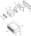
- FIG. 1 is an exploded perspective view of a speaker system according to an embodiment of the present invention.
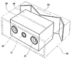
- FIG. 2 is a perspective view of the speaker system shown in FIG. 1.
- FIG. 2 is a perspective view of the speaker system shown in FIG. 1.
- FIG. 3 is a cross-sectional view of the speaker system of FIG.
- FIG. 1 is an exploded perspective view of a speaker system according to an embodiment of the present invention
- FIG. 2 is a perspective view of the speaker system shown in FIG. 1
- FIG. 3 is a cutaway view of the center of the speaker system shown in FIG. 2. It is a cross section.
- the speaker system is formed including a high-pitched speaker 10, a mid-range speaker 20, a low-pitched speaker 30, and a reflecting plate 40 ,
- the first case 50, the second case 60, the partition wall 70, and the outer case 80 are further formed.
- the treble loudspeaker 10 is also called a tweeter, and is installed in the first case 50 so as to face the sound outlet 80a of the outer case 80, which is responsible for reproducing the treble band portion and whose sound is generated in front.
- the mid-speaker 20 is also called a mid woofer, and is installed in the first case 50 so as to face the sound outlet 80a of the outer case 80, which is responsible for reproducing the mid-band portion and generating sound in front.
- the midrange speaker 20 may be formed in two and formed on both sides of the treble speaker 10.
- the bass speaker 30, also referred to as a woofer, is responsible for reproducing the bass band portion, and the second case 60 so that the direction of sound generation is directed toward the rear surface facing the sound outlet 80a of the outer case 80. ) Is combined.
- the bass speaker 30 is composed of the first bass speaker 31 and the second bass speaker 32 may be installed in the second case 60, each composed of two bass speakers 30 The output of the bass sound can be improved by dispersing the generated bass sound.
- the treble speaker 10, the mid-range speaker 20 and the bass speaker 30 is a kind of magnet coil speaker using a magnet, a coil and a diaphragm.
- the reflection plate 40 is installed at the rear of the bass speaker 30 to serve to reflect the bass sound reproduced toward the rear of the bass speaker 30.
- the reflective plate 40 may include a first reflecting portion 41, a second reflecting portion 42, a third reflecting portion 43, and a fourth reflecting portion 44.
- the first reflecting portion 41 is formed in the low-emission passage 84 between the outer case 80 and the first bass speaker 31.
- one end of the first reflector 41 is disposed between the first bass speaker 31 and the second bass speaker 32 of the second case 60, and the other end thereof is the first bass speaker 31.
- the first reflecting portion 41 serves to primarily reflect the sound reproduced by the first bass speaker 31 and emit it to the low sound emission path 84.
- the second reflecting portion 42 is formed in the low emission path 84 between the outer case 80 and the second bass speaker (32).
- one end of the second reflector 42 is disposed between the first bass speaker 31 and the second bass speaker 32 of the second case 60, and the other end thereof is the second bass speaker 32.
- the second reflecting unit 42 primarily reflects the sound reproduced by the second bass speaker 32 and emits the sound to the low sound emission path 84.
- one end of the first reflecting portion 41 and one end of the second reflecting portion 42 are connected, and the other end of the first reflecting portion 41 and the other end of the second reflecting portion 42 are It is connected to the inner surface of the outer case 80 to form a sealed space 90 in the inside of the outer case 80, and utilizes the sealed space 90 as the resonance absorption area.
- the closed space (90) absorbs the resonance sound when the negative resonance is formed in the first bass speaker (31) and the second bass speaker (32), and then resonates in the inner closed space (90, 90). It revolves around the sound and reduces the resonance sound.
- the third reflecting portion 43 has one end coupled to the vicinity of the other end of the first reflecting portion 41 and the outer case 80 is connected, the other end so as to form a predetermined angle with the first reflecting portion 41 Is connected to the inner side of the outer case (80).
- the third reflecting unit 43 secondly reflects the sound of the first bass speaker 31 reflected from the first reflecting unit 41 to the low sound emission path 84 of the first bass speaker 31.
- the fourth reflecting portion 44 is coupled to the other end of the second reflecting portion 42 and the vicinity of the outer case 80 is connected, the other end so as to form a predetermined angle with the second reflecting portion 42. Is connected to the inner side of the outer case (80).
- the third reflecting unit 43 secondly reflects the sound of the second bass speaker 32 reflected from the second reflecting unit 42, and the bass emission path 84 of the second bass speaker 32 is reduced.
- the first case 50 is formed in a box shape and is coupled to the diaphragm of the treble speaker 10 and the mid-range speaker 20 on one side thereof.
- the first case 50 forms a space on the inner side to reduce resonance or reverberation of sounds reproduced by the high-pitched speaker 10 and the mid-range speaker 20.
- the second case 60 is formed in a box shape and is coupled to the diaphragm of the bass speaker 30 on one side thereof.
- the second case 60 forms a space on the inner side to reduce resonance or reverberation of sound reproduced by the first bass speaker 31 and the second bass speaker 32.
- the first case 50 is disposed inside the outer case 80 such that the sound reproduction direction of the high pitch speaker 10 and the middle loudspeaker 20 faces the sound outlet 80a.
- the second case 60 is disposed inside the outer case 80 such that the sound reproducing direction of the bass speaker 30 faces in the direction opposite to the sound outlet 80a.
- the partition wall 70 connects the first case 50 and the second case 60 and blocks a path through which sound is transmitted between the first case 50 and the second case 60.
- the partition wall 70 is in the second case 60 coupled with the reverberation of the high and mid-range generated in the first case 50 coupled with the treble speaker 10 and the mid-range speaker 20 and the bass speaker 30
- the reverberation of the generated low sound does not overlap inside the outer case 80 so that a smooth sound is reproduced.
- the outer case 80 has a sound outlet (80a) consisting of a plurality of through holes on one surface is formed in a box shape, the first case 50, the second case 60 and the reflecting plate 40 to the inside Accept.
- the outer case 80 has a body portion 81 which is open at both ends and is formed in a box shape, and a front cover portion 82 having an acoustic outlet 80a and coupled to the front portion of the body portion 81; It may be formed including a rear cover portion 83 coupled to the rear opening of the body portion 81.
- the outer case 80 may be further formed with a speaker wire connection terminal (not shown) connected to the high-pitched speaker 10, the mid-range speaker 20 and the low-pitched speaker 30 on the outside.
- the first case 50 and the second case 60 is installed in the central portion of the outer case 80 to form a distance with the inner surface of the outer case 80 to form a low sound emission path 84 can do.
- the bass discharge passage 84 serves to direct the bass reproduced by the first bass speaker 31 and the second bass speaker 32 to the sound outlet 80a of the outer case 80.
- the high and mid-ranges reproduced by the high-pitched speaker 10 and the mid-range speaker 20 are reproduced directly toward the sound outlet 80a and the low-pitched speaker when the sound is reproduced.
- the bass generated in 30) is discharged to the sound outlet through the reflector and the low sound emission path 84 in a state discharged to the rear.
- the speaker system takes a 3-way scheme for reproducing high and mid and low sounds with the high and low loudspeakers 10, the mid and high loudspeakers 20, and the low loudspeakers 30, and the external low frequencies.
- the reflection plate 40 By reflecting the reflection plate 40 inside the case 80, a richer bass sound can be realized than a conventional speaker system having the same size.
- the speaker system according to an embodiment of the present invention can reproduce rich bass even in a narrow space than a conventional speaker system.
- the treble or mid-range generated by the loudspeaker 10 and the mid-range speaker 20 is configured in a form accommodated in the case so as to absorb the reverberation itself, the bass of the woofer speaker 30 is the reflecting plate 40 By the sealed space 90 between the outer case 80 and the resonance and reverberation due to bass can be reduced.
- the present invention relates to a speaker system, and can be widely used in a 3-way speaker system having improved bass performance.
Landscapes
- Physics & Mathematics (AREA)
- Engineering & Computer Science (AREA)
- Acoustics & Sound (AREA)
- Signal Processing (AREA)
- Health & Medical Sciences (AREA)
- Otolaryngology (AREA)
- Details Of Audible-Bandwidth Transducers (AREA)
- Obtaining Desirable Characteristics In Audible-Bandwidth Transducers (AREA)
Abstract
La présente invention porte sur un système de haut-parleur. Le problème technique à résoudre est celui de fournir un système de haut-parleur qui peut améliorer l'émission de son de volume bas même dans un espace étroit. A cette fin, un haut-parleur à son de volume fort (10) et un haut-parleur à son de volume intermédiaire (20) sont installés de sorte que la direction du son généré par les haut-parleurs (10, 20) soit dirigée dans une direction vers l'avant et un haut-parleur à son de volume bas (30) est installé de sorte que la direction du son généré par le haut-parleur à son de volume bas (30) soit dirigée dans une direction vers l'arrière. Une plaque réflectrice (40) est en outre installée au niveau de la surface arrière du haut-parleur à son de volume bas (30) de façon à réfléchir le son de volume bas généré dans une direction vers l'arrière à partir du haut-parleur à son de volume bas (30).
Applications Claiming Priority (2)
| Application Number | Priority Date | Filing Date | Title |
|---|---|---|---|
| KR10-2011-0010794 | 2011-02-07 | ||
| KR1020110010794A KR101044222B1 (ko) | 2011-02-07 | 2011-02-07 | 스피커 시스템 |
Publications (2)
| Publication Number | Publication Date |
|---|---|
| WO2012108667A2 true WO2012108667A2 (fr) | 2012-08-16 |
| WO2012108667A3 WO2012108667A3 (fr) | 2012-12-20 |
Family
ID=44406046
Family Applications (1)
| Application Number | Title | Priority Date | Filing Date |
|---|---|---|---|
| PCT/KR2012/000887 Ceased WO2012108667A2 (fr) | 2011-02-07 | 2012-02-07 | Système de haut-parleur |
Country Status (2)
| Country | Link |
|---|---|
| KR (1) | KR101044222B1 (fr) |
| WO (1) | WO2012108667A2 (fr) |
Cited By (1)
| Publication number | Priority date | Publication date | Assignee | Title |
|---|---|---|---|---|
| KR101538771B1 (ko) * | 2015-02-26 | 2015-07-23 | 공관식 | 스피커 |
Families Citing this family (4)
| Publication number | Priority date | Publication date | Assignee | Title |
|---|---|---|---|---|
| KR101538901B1 (ko) * | 2015-05-20 | 2015-07-22 | 오철환 | 스피커 시스템 |
| KR101538770B1 (ko) * | 2015-05-27 | 2015-07-22 | 공관식 | 스피커 |
| KR101820896B1 (ko) | 2017-01-20 | 2018-01-22 | 송인관 | 스피커의 유닛이 인클로저에 장착된 오디오용 스피커 |
| US11991497B1 (en) * | 2022-10-28 | 2024-05-21 | xMEMS Labs, Inc. | Acoustic device and holder flattening frequency response |
Family Cites Families (4)
| Publication number | Priority date | Publication date | Assignee | Title |
|---|---|---|---|---|
| JPS5825793A (ja) * | 1981-08-10 | 1983-02-16 | Yuutopia Kiki Kk | スピ−カ−用キヤビネツト |
| KR940003855B1 (ko) * | 1991-10-30 | 1994-05-03 | 삼성전기 주식회사 | 이중구조 드라이브(Double Base Drive) 방식의 스피커 시스템 |
| JP3664043B2 (ja) * | 2000-05-23 | 2005-06-22 | 松下電器産業株式会社 | スピーカシステム |
| JP2002095078A (ja) * | 2000-09-20 | 2002-03-29 | Sanyo Electric Co Ltd | スピーカ装置 |
-
2011
- 2011-02-07 KR KR1020110010794A patent/KR101044222B1/ko not_active Expired - Fee Related
-
2012
- 2012-02-07 WO PCT/KR2012/000887 patent/WO2012108667A2/fr not_active Ceased
Cited By (1)
| Publication number | Priority date | Publication date | Assignee | Title |
|---|---|---|---|---|
| KR101538771B1 (ko) * | 2015-02-26 | 2015-07-23 | 공관식 | 스피커 |
Also Published As
| Publication number | Publication date |
|---|---|
| WO2012108667A3 (fr) | 2012-12-20 |
| KR101044222B1 (ko) | 2011-06-23 |
Similar Documents
| Publication | Publication Date | Title |
|---|---|---|
| US7103193B2 (en) | Bandpass woofer enclosure with multiple acoustic fibers | |
| CN1075316C (zh) | 电视机的扬声器系统 | |
| US9998809B2 (en) | Loudspeaker module | |
| US6343134B1 (en) | Loudspeaker and horn with an additional transducer | |
| WO2019177324A1 (fr) | Écouteur ayant des moyens d'égalisation de pression | |
| DK156454B (da) | Hoejttalerenhed med mere end en bas/mellemtone-hoejttaler | |
| WO2012108667A2 (fr) | Système de haut-parleur | |
| WO2015002407A1 (fr) | Appareil de génération de son, et appareil électronique le comprenant | |
| WO2015142095A1 (fr) | Haut-parleur de type en treillis et système de haut-parleurs en réseau de type en treillis le comprenant | |
| CN102714768B (zh) | 平面扬声器 | |
| WO2015026145A1 (fr) | Haut-parleur à deux voies ayant un effet coaxial | |
| US6038326A (en) | Loudspeaker and horn with an additional transducer | |
| US11647323B2 (en) | Loudspeaker | |
| WO2024000687A1 (fr) | Haut-parleur coaxial | |
| WO2023185412A1 (fr) | Module de production de son et dispositif électronique | |
| US6731765B1 (en) | Loudspeaker device | |
| WO2016186471A1 (fr) | Système de haut-parleur | |
| JP2010504655A5 (fr) | ||
| JP5182683B2 (ja) | スピーカシステム | |
| CN119485119A (zh) | 在宽频范围内减少后侧声音辐射的扬声器系统 | |
| WO2014081092A1 (fr) | Amplificateur de haut-parleur à pavillon | |
| JP2010050863A (ja) | スピーカーシステム | |
| CN223872395U (zh) | 一种扬声装置 | |
| CN217445502U (zh) | 一种家庭影院回音壁音箱 | |
| WO2015141983A1 (fr) | Dispositif de haut-parleur |
Legal Events
| Date | Code | Title | Description |
|---|---|---|---|
| 121 | Ep: the epo has been informed by wipo that ep was designated in this application |
Ref document number: 12744817 Country of ref document: EP Kind code of ref document: A2 |
|
| NENP | Non-entry into the national phase |
Ref country code: DE |
|
| 122 | Ep: pct application non-entry in european phase |
Ref document number: 12744817 Country of ref document: EP Kind code of ref document: A2 |