WO2012111071A1 - Catalyseur à chauffage électrique - Google Patents
Catalyseur à chauffage électrique Download PDFInfo
- Publication number
- WO2012111071A1 WO2012111071A1 PCT/JP2011/053037 JP2011053037W WO2012111071A1 WO 2012111071 A1 WO2012111071 A1 WO 2012111071A1 JP 2011053037 W JP2011053037 W JP 2011053037W WO 2012111071 A1 WO2012111071 A1 WO 2012111071A1
- Authority
- WO
- WIPO (PCT)
- Prior art keywords
- inner tube
- case
- temperature
- mat
- heat
- Prior art date
- Legal status (The legal status is an assumption and is not a legal conclusion. Google has not performed a legal analysis and makes no representation as to the accuracy of the status listed.)
- Ceased
Links
Images





Classifications
-
- H—ELECTRICITY
- H05—ELECTRIC TECHNIQUES NOT OTHERWISE PROVIDED FOR
- H05B—ELECTRIC HEATING; ELECTRIC LIGHT SOURCES NOT OTHERWISE PROVIDED FOR; CIRCUIT ARRANGEMENTS FOR ELECTRIC LIGHT SOURCES, IN GENERAL
- H05B1/00—Details of electric heating devices
-
- F—MECHANICAL ENGINEERING; LIGHTING; HEATING; WEAPONS; BLASTING
- F01—MACHINES OR ENGINES IN GENERAL; ENGINE PLANTS IN GENERAL; STEAM ENGINES
- F01N—GAS-FLOW SILENCERS OR EXHAUST APPARATUS FOR MACHINES OR ENGINES IN GENERAL; GAS-FLOW SILENCERS OR EXHAUST APPARATUS FOR INTERNAL-COMBUSTION ENGINES
- F01N3/00—Exhaust or silencing apparatus having means for purifying, rendering innocuous, or otherwise treating exhaust
- F01N3/08—Exhaust or silencing apparatus having means for purifying, rendering innocuous, or otherwise treating exhaust for rendering innocuous
- F01N3/10—Exhaust or silencing apparatus having means for purifying, rendering innocuous, or otherwise treating exhaust for rendering innocuous by thermal or catalytic conversion of noxious components of exhaust
- F01N3/18—Exhaust or silencing apparatus having means for purifying, rendering innocuous, or otherwise treating exhaust for rendering innocuous by thermal or catalytic conversion of noxious components of exhaust characterised by methods of operation; Control
- F01N3/20—Exhaust or silencing apparatus having means for purifying, rendering innocuous, or otherwise treating exhaust for rendering innocuous by thermal or catalytic conversion of noxious components of exhaust characterised by methods of operation; Control specially adapted for catalytic conversion
- F01N3/2006—Periodically heating or cooling catalytic reactors, e.g. at cold starting or overheating
- F01N3/2013—Periodically heating or cooling catalytic reactors, e.g. at cold starting or overheating using electric or magnetic heating means
- F01N3/2026—Periodically heating or cooling catalytic reactors, e.g. at cold starting or overheating using electric or magnetic heating means directly electrifying the catalyst substrate, i.e. heating the electrically conductive catalyst substrate by joule effect
-
- F—MECHANICAL ENGINEERING; LIGHTING; HEATING; WEAPONS; BLASTING
- F01—MACHINES OR ENGINES IN GENERAL; ENGINE PLANTS IN GENERAL; STEAM ENGINES
- F01N—GAS-FLOW SILENCERS OR EXHAUST APPARATUS FOR MACHINES OR ENGINES IN GENERAL; GAS-FLOW SILENCERS OR EXHAUST APPARATUS FOR INTERNAL-COMBUSTION ENGINES
- F01N13/00—Exhaust or silencing apparatus characterised by constructional features
- F01N13/14—Exhaust or silencing apparatus characterised by constructional features having thermal insulation
-
- F—MECHANICAL ENGINEERING; LIGHTING; HEATING; WEAPONS; BLASTING
- F01—MACHINES OR ENGINES IN GENERAL; ENGINE PLANTS IN GENERAL; STEAM ENGINES
- F01N—GAS-FLOW SILENCERS OR EXHAUST APPARATUS FOR MACHINES OR ENGINES IN GENERAL; GAS-FLOW SILENCERS OR EXHAUST APPARATUS FOR INTERNAL-COMBUSTION ENGINES
- F01N3/00—Exhaust or silencing apparatus having means for purifying, rendering innocuous, or otherwise treating exhaust
- F01N3/08—Exhaust or silencing apparatus having means for purifying, rendering innocuous, or otherwise treating exhaust for rendering innocuous
- F01N3/10—Exhaust or silencing apparatus having means for purifying, rendering innocuous, or otherwise treating exhaust for rendering innocuous by thermal or catalytic conversion of noxious components of exhaust
- F01N3/18—Exhaust or silencing apparatus having means for purifying, rendering innocuous, or otherwise treating exhaust for rendering innocuous by thermal or catalytic conversion of noxious components of exhaust characterised by methods of operation; Control
- F01N3/20—Exhaust or silencing apparatus having means for purifying, rendering innocuous, or otherwise treating exhaust for rendering innocuous by thermal or catalytic conversion of noxious components of exhaust characterised by methods of operation; Control specially adapted for catalytic conversion
-
- F—MECHANICAL ENGINEERING; LIGHTING; HEATING; WEAPONS; BLASTING
- F01—MACHINES OR ENGINES IN GENERAL; ENGINE PLANTS IN GENERAL; STEAM ENGINES
- F01N—GAS-FLOW SILENCERS OR EXHAUST APPARATUS FOR MACHINES OR ENGINES IN GENERAL; GAS-FLOW SILENCERS OR EXHAUST APPARATUS FOR INTERNAL-COMBUSTION ENGINES
- F01N3/00—Exhaust or silencing apparatus having means for purifying, rendering innocuous, or otherwise treating exhaust
- F01N3/08—Exhaust or silencing apparatus having means for purifying, rendering innocuous, or otherwise treating exhaust for rendering innocuous
- F01N3/10—Exhaust or silencing apparatus having means for purifying, rendering innocuous, or otherwise treating exhaust for rendering innocuous by thermal or catalytic conversion of noxious components of exhaust
- F01N3/24—Exhaust or silencing apparatus having means for purifying, rendering innocuous, or otherwise treating exhaust for rendering innocuous by thermal or catalytic conversion of noxious components of exhaust characterised by constructional aspects of converting apparatus
- F01N3/28—Construction of catalytic reactors
-
- F—MECHANICAL ENGINEERING; LIGHTING; HEATING; WEAPONS; BLASTING
- F01—MACHINES OR ENGINES IN GENERAL; ENGINE PLANTS IN GENERAL; STEAM ENGINES
- F01N—GAS-FLOW SILENCERS OR EXHAUST APPARATUS FOR MACHINES OR ENGINES IN GENERAL; GAS-FLOW SILENCERS OR EXHAUST APPARATUS FOR INTERNAL-COMBUSTION ENGINES
- F01N3/00—Exhaust or silencing apparatus having means for purifying, rendering innocuous, or otherwise treating exhaust
- F01N3/08—Exhaust or silencing apparatus having means for purifying, rendering innocuous, or otherwise treating exhaust for rendering innocuous
- F01N3/10—Exhaust or silencing apparatus having means for purifying, rendering innocuous, or otherwise treating exhaust for rendering innocuous by thermal or catalytic conversion of noxious components of exhaust
- F01N3/24—Exhaust or silencing apparatus having means for purifying, rendering innocuous, or otherwise treating exhaust for rendering innocuous by thermal or catalytic conversion of noxious components of exhaust characterised by constructional aspects of converting apparatus
- F01N3/28—Construction of catalytic reactors
- F01N3/2839—Arrangements for mounting catalyst support in housing, e.g. with means for compensating thermal expansion or vibration
- F01N3/2853—Arrangements for mounting catalyst support in housing, e.g. with means for compensating thermal expansion or vibration using mats or gaskets between catalyst body and housing
-
- F—MECHANICAL ENGINEERING; LIGHTING; HEATING; WEAPONS; BLASTING
- F01—MACHINES OR ENGINES IN GENERAL; ENGINE PLANTS IN GENERAL; STEAM ENGINES
- F01N—GAS-FLOW SILENCERS OR EXHAUST APPARATUS FOR MACHINES OR ENGINES IN GENERAL; GAS-FLOW SILENCERS OR EXHAUST APPARATUS FOR INTERNAL-COMBUSTION ENGINES
- F01N3/00—Exhaust or silencing apparatus having means for purifying, rendering innocuous, or otherwise treating exhaust
- F01N3/08—Exhaust or silencing apparatus having means for purifying, rendering innocuous, or otherwise treating exhaust for rendering innocuous
- F01N3/10—Exhaust or silencing apparatus having means for purifying, rendering innocuous, or otherwise treating exhaust for rendering innocuous by thermal or catalytic conversion of noxious components of exhaust
- F01N3/24—Exhaust or silencing apparatus having means for purifying, rendering innocuous, or otherwise treating exhaust for rendering innocuous by thermal or catalytic conversion of noxious components of exhaust characterised by constructional aspects of converting apparatus
- F01N3/28—Construction of catalytic reactors
- F01N3/2839—Arrangements for mounting catalyst support in housing, e.g. with means for compensating thermal expansion or vibration
- F01N3/2853—Arrangements for mounting catalyst support in housing, e.g. with means for compensating thermal expansion or vibration using mats or gaskets between catalyst body and housing
- F01N3/2871—Arrangements for mounting catalyst support in housing, e.g. with means for compensating thermal expansion or vibration using mats or gaskets between catalyst body and housing the mats or gaskets having an additional, e.g. non-insulating or non-cushioning layer, a metal foil or an adhesive layer
-
- F—MECHANICAL ENGINEERING; LIGHTING; HEATING; WEAPONS; BLASTING
- F01—MACHINES OR ENGINES IN GENERAL; ENGINE PLANTS IN GENERAL; STEAM ENGINES
- F01N—GAS-FLOW SILENCERS OR EXHAUST APPARATUS FOR MACHINES OR ENGINES IN GENERAL; GAS-FLOW SILENCERS OR EXHAUST APPARATUS FOR INTERNAL-COMBUSTION ENGINES
- F01N2240/00—Combination or association of two or more different exhaust treating devices, or of at least one such device with an auxiliary device, not covered by indexing codes F01N2230/00 or F01N2250/00, one of the devices being
- F01N2240/16—Combination or association of two or more different exhaust treating devices, or of at least one such device with an auxiliary device, not covered by indexing codes F01N2230/00 or F01N2250/00, one of the devices being an electric heater, i.e. a resistance heater
-
- Y—GENERAL TAGGING OF NEW TECHNOLOGICAL DEVELOPMENTS; GENERAL TAGGING OF CROSS-SECTIONAL TECHNOLOGIES SPANNING OVER SEVERAL SECTIONS OF THE IPC; TECHNICAL SUBJECTS COVERED BY FORMER USPC CROSS-REFERENCE ART COLLECTIONS [XRACs] AND DIGESTS
- Y02—TECHNOLOGIES OR APPLICATIONS FOR MITIGATION OR ADAPTATION AGAINST CLIMATE CHANGE
- Y02T—CLIMATE CHANGE MITIGATION TECHNOLOGIES RELATED TO TRANSPORTATION
- Y02T10/00—Road transport of goods or passengers
- Y02T10/10—Internal combustion engine [ICE] based vehicles
- Y02T10/12—Improving ICE efficiencies
Definitions
- the present invention relates to an electrically heated catalyst.
- the temperature of the exhaust gas introduced into the catalyst is maintained at a high temperature to improve the exhaust purification performance, and the exhaust pipe surface temperature is increased.
- the technique to suppress is known (for example, refer patent document 3).
- the present invention has been made in view of the above problems, and an object thereof is to suppress the flow of electricity to the case of the electrically heated catalyst.
- an electrically heated catalyst provides: A heating element that generates heat when energized; A case for housing the heating element; An inner pipe provided between the heating element and the case; A mat for insulating electricity provided between the heating element and the inner tube and between the inner tube and the case; With The inner pipe protrudes upstream and downstream in the exhaust flow direction from the mat, and is composed of at least two substances having different thermal conductivities, and has a lower thermal conductivity on the inner side than the surface. The material having the higher thermal conductivity is disposed so as to surround the material having the lower thermal conductivity.
- the heating element may be a catalyst carrier or may be provided upstream of the catalyst. Since the heating element generates heat by energizing the heating element, the temperature of the catalyst can be increased.
- the inner tube divides the mat into a case side and a heating element side. Further, since the inner tube is supported by the mat, the inner tube is not in contact with the heating element and the case.
- particulate matter sometimes accumulates at a location protruding from the inner pipe mat when the temperature of the exhaust gas is low.
- the particulate matter can be oxidized at a lower temperature as the oxygen concentration is higher.
- the particulate matter is difficult to be oxidized because the oxygen concentration is low and the exhaust temperature is low.
- the exhaust temperature is low, when operating at a lean air-fuel ratio or when performing fuel cut during deceleration, the oxygen concentration in the exhaust becomes high, so that particulate matter can be oxidized. it can.
- the thermal conductivity on the surface side is higher than the inner side in the wall of the inner pipe, the temperature of the inner pipe is increased from the start of the internal combustion engine to the time of acceleration, and the speed is reduced.
- the temperature drop of the inner pipe can be suppressed. That is, the heat obtained by the inner pipe from the exhaust gas at the time of starting or accelerating the internal combustion engine is mainly conducted on the surface side on which the material having high thermal conductivity is disposed, so that the surface temperature of the inner pipe becomes high.
- heat is taken from the inner pipe by the low-temperature exhaust, so that the surface temperature of the inner pipe decreases.
- the particulate matter adhering to the outer peripheral surface of the inner pipe can be oxidized even during deceleration when the oxygen concentration in the exhaust gas is high. Therefore, it can suppress that electricity flows on the surface of an inner pipe.
- an electrode connected to the heating element from the outside of the case, A space formed around the electrode between the case and the heating element, and an electrode chamber formed by providing a gap between the electrode and the mat and the inner tube;
- the inner tube may have a portion formed of only the material having the higher thermal conductivity around the electrode chamber.
- the water absorbed by the mat moves in the mat, but the movement of water from the case side to the heating element side is blocked by the inner tube. If it does so, the short circuit by water can be suppressed. Further, the water absorbed by the mat evaporates due to the heat of the exhaust and the heat of the heating element, so that it is removed over time.
- the electrode chamber when water absorbed by the mat reaches the electrode chamber, it becomes difficult to remove the water from the electrode chamber. If water remains in the electrode chamber, there is a risk of a short circuit. In order to remove water in the electrode chamber, it is effective to increase the temperature of the electrode chamber. However, if the heat insulation effect of the inner tube is high, it is difficult to increase the temperature of the electrode chamber. On the other hand, if the periphery of the electrode chamber is composed only of a material having a higher thermal conductivity, more heat generated in the heating element and heat of the exhaust can be supplied to the electrode chamber. The temperature can be increased early. This makes it possible to quickly remove the water in the electrode chamber by evaporating it. The distance from the material having the lower thermal conductivity to the electrode chamber may be longer than the distance from the material having the lower thermal conductivity to the upstream end of the inner tube.
- the inner tube has a portion composed of only the material having the higher thermal conductivity, and the material having the lower thermal conductivity is located on the inner side of the surface upstream of the portion.
- the material having the higher thermal conductivity may be arranged so as to surround the material having the lower thermal conductivity.
- the temperature of the inner pipe is higher at the upstream side than at the downstream side during deceleration. That is, the temperature of the upstream portion of the inner pipe is likely to decrease due to the circulation of the low-temperature exhaust during deceleration.
- the downstream portion of the inner pipe can receive heat from the heating element even when the temperature of the exhaust gas flowing into the heating element is low. Since this heat generating body has a large heat capacity, even if exhaust gas having a low temperature passes, the temperature hardly decreases. For this reason, it is difficult for temperature to fall in the downstream part of an inner pipe. Further, since the amount of exhaust is small during deceleration, the influence of heat released from the case to the outside is relatively large.
- the temperature of the outer peripheral surface of the inner tube tends to decrease. Therefore, it is better to suppress the decrease in the temperature of the outer peripheral surface of the inner pipe by relatively increasing the heat conductivity inside the inner pipe at the downstream side of the inner pipe. Moreover, although it becomes easy to overheat by the heat of a heat generating body in the downstream of an inner pipe, overheating can be suppressed by making comparatively high the heat conductivity inside an inner pipe.
- an electrode connected to the heating element from the outside of the case, A space formed around the electrode between the case and the heating element, and an electrode chamber formed by providing a gap between the electrode and the mat and the inner tube;
- electricity can be prevented from flowing through the case of the electrically heated catalyst.
- FIG. 1 is a diagram showing a schematic configuration of an electrically heated catalyst according to Example 1.
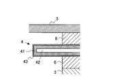
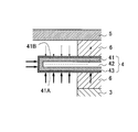
- FIG. It is an enlarged view of the section of an inner pipe. It is the figure which showed the mode of the movement of the heat
- FIG. 3 is a diagram showing a schematic configuration of an electrically heated catalyst according to Example 2.
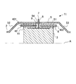
- FIG. 4 is a diagram showing a schematic configuration of an electrically heated catalyst according to Example 3.
- FIG. 1 is a diagram showing a schematic configuration of an electrically heated catalyst 1 according to the first embodiment.
- the electrically heated catalyst 1 according to this embodiment is provided in the exhaust pipe 2 of the internal combustion engine mounted on the vehicle.
- the internal combustion engine may be a diesel engine or a gasoline engine. It can also be used in a vehicle that employs a hybrid system equipped with an electric motor.
- FIG. 1 is a cross-sectional view of the electrically heated catalyst 1 cut in the longitudinal direction along the central axis A of the exhaust pipe 2.
- the electrically heated catalyst 1 shown in FIG. Since the shape of the electrically heated catalyst 1 is symmetrical with respect to the central axis A, only the upper part is shown in FIG.
- the electrically heated catalyst 1 includes a cylindrical catalyst carrier 3 centering on a central axis A.
- a catalyst carrier 3, an inner tube 4, and a case 5 are provided in this order from the central axis A side.
- a mat 6 is provided between the catalyst carrier 3 and the inner tube 4 and between the inner tube 4 and the case 5.
- the catalyst carrier 3 is made of a material that generates electrical resistance and generates heat when energized.
- SiC is used as the material of the catalyst carrier 3.
- the catalyst carrier 3 has a plurality of passages extending in the direction in which the exhaust flows (that is, in the direction of the central axis A) and having a cross section perpendicular to the direction in which the exhaust flows in a honeycomb shape. Exhaust gas flows through this passage.
- the outer shape of the catalyst carrier 3 is, for example, a cylindrical shape centered on the central axis A of the exhaust pipe 2.
- the cross-sectional shape of the catalyst carrier 3 having a cross section orthogonal to the central axis A may be, for example, an ellipse.
- the central axis A is a central axis common to the exhaust pipe 2, the catalyst carrier 3, the inner pipe 4, and the case 5.
- the catalyst is supported on the catalyst carrier 3.
- the catalyst include an oxidation catalyst, a three-way catalyst, an NOx storage reduction catalyst, and a selective reduction NOx catalyst.
- Two electrodes 7 are connected to the catalyst carrier 3, and the catalyst carrier 3 is energized by applying a voltage between the electrodes 7.
- the catalyst carrier 3 generates heat due to the electrical resistance of the catalyst carrier 3.
- the catalyst carrier 3 corresponds to the heating element in the present invention. Further, even when the heating element is provided on the upstream side of the catalyst, the present embodiment can be similarly applied.
- an electrical insulating material is used, for example, a ceramic fiber mainly composed of alumina.
- the mat 6 is wound around the outer peripheral surface of the catalyst carrier 3 and the outer peripheral surface of the inner tube 4. Since the mat 6 covers the outer peripheral surface of the catalyst carrier 3 (a surface parallel to the central axis A), electricity is prevented from flowing to the inner tube 4 and the case 5 when the catalyst carrier 3 is energized. .
- the inner tube 4 is formed in a tubular shape around the central axis A.
- the inner tube 4 is longer in the central axis A direction than the mat 6. For this reason, the inner tube 4 protrudes from the mat 6 to the upstream side and the downstream side.
- the inner diameter of the inner tube 4 is substantially the same as the outer diameter of the mat 6 when the outer periphery of the catalyst carrier 3 is covered with the mat 6.
- FIG. 2 is an enlarged view of a cross section of the inner tube 4.
- the inner tube 4 includes an outer layer 41, an inner layer 42, and an insulating layer 43.
- the inner layer 42 is disposed inside the cross section of the inner tube 4.
- the outer layer 41 surrounds the entire inner layer 42, and the insulating layer 43 surrounds the entire outer layer 41.
- a material having a higher thermal conductivity than the inner layer 42 is used.
- any of gas, liquid, and solid can be used.
- air can be used for the inner layer 42 and stainless steel material can be used for the outer layer 41.
- the cross section of the inner tube 4 has a hollow structure in which the air layer (inner layer 42) is surrounded by the stainless steel layer (outer layer 41). If the outer layer 41 has a higher thermal conductivity than the inner layer 42, other materials can be used.
- the insulating layer 43 is formed by applying an electrical insulator such as ceramic to the outer layer 41, for example.
- a stainless steel material is selected as the outer layer 41 and air is selected as the inner layer 42.
- the material of the case 5 is a metal, and for example, a stainless steel material can be used.
- the case 5 includes an accommodating portion 51 that includes a curved surface parallel to the central axis A, and a tapered portion 52 that connects the accommodating portion 51 and the exhaust pipe 2 on the upstream side and the downstream side of the accommodating portion 51. 53.
- the catalyst carrier 3, the inner tube 4, and the mat 6 are accommodated inside the accommodating portion 51.
- the tapered portions 52 and 53 have a tapered shape in which the passage cross-sectional area decreases as the distance from the accommodating portion 51 increases. That is, the taper portion 52 upstream of the catalyst carrier 3 has a smaller sectional area toward the upstream side, and the taper portion 53 downstream of the catalyst carrier 3 has a smaller sectional area toward the downstream side.
- the inner diameter of the accommodating portion 51 is substantially the same as the outer diameter of the mat 6 when the outer periphery of the inner tube 4 is covered with the mat 6.
- Two electrodes 7 are connected to the catalyst carrier 3.
- holes 40 and 54 are provided in the inner tube 4 and the case 5.
- the inner layer 42 is surrounded by the outer layer 41, and the outer layer 41 is surrounded by the insulating layer 43.
- the mat 6 is not provided around the electrode 7 until the electrode 7 is connected to the catalyst carrier 3.
- An insulating material 8 that supports the electrode 7 is provided in the hole 54 formed in the case 5.
- the insulating material 8 is provided between the case 5 and the electrode 7 without a gap. In this manner, an electrode chamber 9 that is a closed space around the electrode 7 is formed in the case 5.
- the inner tube 4 may be divided into an upstream side and a downstream side with respect to the electrode chamber 9 and may be installed separately.
- the mat 6 may also be divided into an upstream side and a downstream side with respect to the electrode chamber 9 and may be installed separately from each other. As a result, the electrode chamber 9 goes around the catalyst carrier 3 once.
- water condensed on the upstream side of the catalyst carrier 3 may flow on the inner wall of the exhaust pipe 2 or the case 5 and adhere to the mat 6.
- the water adheres to the mat 6 between the inner tube 4 and the accommodating portion 51. That is, since the inner tube 4 protrudes upstream and downstream of the mat 6, water is prevented from entering the inner tube 4. Thereby, it is suppressed that the case 5 and the catalyst carrier 3 are short-circuited by water at the upstream end and the downstream end of the mat 6.
- the case 5 and the catalyst carrier 3 may be short-circuited by the PM.
- the inner tube 4 protrudes from the mat 6 and the temperature of the protruding portion is increased due to the heat of the exhaust, the PM adhering to the inner tube 4 can be oxidized and removed. Thereby, it is suppressed that case 5 and the catalyst support
- the surface temperature of the inner pipe 4 rapidly rises when the inner pipe 4 receives heat from the exhaust gas when starting or accelerating the internal combustion engine.
- FIG. 3 is a diagram showing a state of heat transfer during acceleration. Since the exhaust gas mainly flows on the catalyst carrier 3 side than the inner tube 4, it receives more heat on the inner peripheral surface side 41A than on the outer peripheral surface side 41B of the inner tube 4 during acceleration. Further, the inner peripheral surface side 41 ⁇ / b> A of the inner tube 4 also receives heat from the catalyst carrier 3. In FIG. 3, the magnitude of the heat received is indicated by the thickness of the arrow. These heats are transmitted through the outer layer 41 having a relatively high thermal conductivity. Further, since the inner layer 42 having a relatively low thermal conductivity exists, it is possible to prevent heat from moving through the inner layer 42 and transferring heat from the inner peripheral surface side 41A of the inner tube 4 to the case 5 (see FIG. (See dashed line 3). For this reason, the temperature of the inner peripheral surface side 41A of the inner tube 4 rises quickly and the temperature becomes higher.
- both the outer layer 41 and the inner layer 42 of the inner tube 4 are made of a stainless steel material, heat is easily transferred from the inner peripheral surface 41A of the inner tube 4 to the inner layer 42. Therefore, the mat between the inner tube 4 and the case 5 is used. Heat can easily escape to the case 5 via the 6. For this reason, it becomes difficult for the surface temperature of the inner tube 4 to rise.
- the surface temperature of the inner tube 4 is high when the oxygen concentration in the exhaust gas is high.
- the oxygen concentration in the exhaust gas becomes high at the time of fuel cut during deceleration, if the surface temperature of the inner tube 4 is high at this time, it is possible to oxidize PM.
- the surface temperature of the inner pipe 4 is likely to decrease because the exhaust temperature is low. This temperature decrease is remarkable on the inner peripheral surface side 41A of the inner pipe 4 through which more exhaust gas flows.
- the inner tube 4 since the inner tube 4 includes the inner layer 42, even if the surface temperature is lowered on the inner peripheral surface side 41 ⁇ / b> A of the inner tube 4, the heat insulating effect of the inner layer 42 causes the outer peripheral surface side 41 ⁇ / b> B of the inner tube 4. It can suppress that temperature falls.
- FIG. 4 is a time chart showing the transition between the temperature on the inner peripheral surface side 41A of the inner tube 4 and the temperature on the outer peripheral surface side 41B.
- steady operation is performed, and after the time indicated by A, the vehicle is decelerating and the fuel cut is performed.
- “With inner layer” indicates a case where stainless steel material is used for the outer layer 41 of the inner tube 4 and air is used for the inner layer 42, and “without inner layer” means that the outer layer 41 and the inner layer 42 of the inner tube 4 are used. The case where a stainless steel material is used is shown.
- the solid line indicates the temperature on the outer peripheral surface side 41B of the inner tube 4
- the alternate long and short dash line indicates the temperature on the inner peripheral surface side 41A of the inner tube 4
- the broken line indicates the temperature of the exhaust gas flowing into the electrically heated catalyst 1. Yes.
- the temperature indicated by B is a lower limit value of the temperature at which PM can be oxidized.
- the thermal conductivity of the inner layer 42 of the inner tube 4 is made lower than the thermal conductivity of the outer layer 41, thereby promoting the temperature rise of the inner tube 4, and
- the temperature drop of the inner tube 4 at the time of fuel cut can be suppressed. That is, the temperature of the inner peripheral surface side 41 ⁇ / b> A of the inner tube 4 can be increased during acceleration due to the heat insulating effect of the inner layer 42. Further, since the temperature drop on the outer peripheral surface side 41B of the inner pipe 4 is suppressed during deceleration, PM oxidation can be promoted on the outer peripheral surface side 41B.
- the outer peripheral surface side 41B of the inner tube 4 has a smaller amount of PM attached than the inner peripheral surface side 41A. Therefore, suppressing the temperature drop on the outer peripheral surface side 41B of the inner tube 4 is an effective means for suppressing a short circuit.
- FIG. 5 is a diagram showing a schematic configuration of the electrically heated catalyst 10 according to the second embodiment. Differences from the electrically heated catalyst 1 shown in Example 1 will be described. In addition, the same code
- FIG. 5 is a diagram showing a schematic configuration of the electrically heated catalyst 10 according to the second embodiment. Differences from the electrically heated catalyst 1 shown in Example 1 will be described. In addition, the same code
- the water adhering to the mat 6 evaporates due to the heat of the exhaust and the heat of the catalyst carrier 3.
- the amount of water adhering to the mat 6 increases, a part of the water does not immediately evaporate and stays in the mat 6. Then, water may reach the electrode chamber 9 around the electrode 7 through the mat 6 and stay in the electrode chamber 9. In this way, the water present in the electrode chamber 9 is difficult to remove even if it evaporates. If water vapor is present in the electrode chamber 9, the insulation resistance between the electrode 7 and the case 5 is greatly reduced. If it does so, when there exists a request
- the thermal conductivity inside the inner tube 4 is lowered as in the first embodiment, the heat from the catalyst carrier 3 is difficult to be transmitted to the electrode chamber 9, so that the temperature of the electrode chamber 9 is difficult to rise. For this reason, water tends to remain inside the electrode chamber 9.
- the structure of the inner tube 400 is different from the first embodiment.
- the area around the electrode chamber 9 of the inner tube 400 (a region surrounded by a broken line in FIG. 5) is composed of only a material having high thermal conductivity. That is, the distance from the inner layer 45 to the electrode chamber 9 is longer than that in the first embodiment. This may be such that the region of the inner layer 45 is made smaller in the direction away from the electrode chamber 9, and the region of the outer layer 44 may be made larger in the direction away from the electrode chamber 9. Further, the distance from the inner layer 45 to the electrode chamber 9 may be longer than the distance from the inner layer 45 to the upstream end of the inner tube 400. Further, the thermal conductivity of the inner layer 45 and the outer layer 44 may be the same around the electrode chamber 9 of the inner tube 400.
- the electrode chamber 9 may be made of a material having a relatively high thermal conductivity (for example, a stainless steel material) without being hollow.
- the range composed only of the material having high thermal conductivity is set so that the temperature in the electrode chamber 9 can be raised to a temperature necessary for water removal. Further, it may be set so that PM adhering to the inner pipe 400 can be removed.
- the thermal conductivity of the inner layer 45 may be higher than that of the outer layer 44 around the electrode chamber 9 of the inner tube 400.
- the amount of heat transferred from the catalyst carrier 3 to the electrode chamber 9 can be increased. That is, the heat of the exhaust, the heat generated by the reaction of the unburned fuel in the catalyst, the heat generated by energization, and the like can be more conducted to the electrode chamber 9. Thereby, since the temperature in the electrode chamber 9 can be raised rapidly more than dew point temperature, the fall of the insulation performance by condensed water can be suppressed.
- FIG. 6 is a diagram showing a schematic configuration of the electrically heated catalyst 11 according to the third embodiment. Differences from the electrically heated catalyst 1 shown in Example 1 will be described. In addition, the same code
- FIG. 6 is a diagram showing a schematic configuration of the electrically heated catalyst 11 according to the third embodiment. Differences from the electrically heated catalyst 1 shown in Example 1 will be described. In addition, the same code
- the inner tube is divided into an inner tube 401 on the upstream side of the electrode chamber 9 and an inner tube 402 on the downstream side of the electrode chamber 9.
- the mat 6 is also divided into an upstream side and a downstream side from the electrode chamber 9.
- the electrode chamber 9 makes one round around the catalyst carrier 3.
- an insulating layer is provided on the inner tube 401 on the upstream side of the electrode chamber 9 and the inner tube 402 on the downstream side of the electrode chamber 9 as in the first embodiment.
- the thermal conductivity of the inner layer 42 is set lower than that of the outer layer 41.
- the inner tube 402 on the downstream side of the electrode chamber 9 is composed of only the material having the same thermal conductivity as that of the outer layer 41. This may be that the inner tube 402 has the same thermal conductivity between the outer layer and the inner layer. In the present embodiment, the inner tube 402 on the downstream side of the electrode chamber 9 corresponds to a portion composed of only the material having higher thermal conductivity in the present invention.
- FIG. 7 is a graph showing the transition of the temperature of exhaust gas flowing into the electrically heated catalyst 11 (solid line) and the temperature of exhaust gas flowing out of the electrically heated catalyst 11 (dashed line).
- A deceleration is started and fuel cut is performed at the same time.
- B is the lower limit of the temperature at which PM can be oxidized.
- the temperature of the exhaust gas flowing into the electrically heated catalyst 11 immediately decreases due to the fuel cut and becomes lower than the temperature indicated by B. On the other hand, it takes time until the temperature of the exhaust gas flowing out from the electrically heated catalyst 11 becomes lower than the temperature indicated by B. That is, since the electrically heated catalyst 11 has a relatively large heat capacity, even if the temperature of the exhaust gas flowing into the electrically heated catalyst 11 is lowered, heat is applied to the exhaust gas from the electrically heated catalyst 11. The degree of decrease in the temperature of the exhaust gas flowing out from the type catalyst 11 is small. For this reason, the inner tube 402 on the downstream side of the electrode chamber 9 takes longer than the temperature indicated by B than the inner tube 401 on the upstream side of the electrode chamber 9.
- the flow rate of the exhaust gas is small, so the influence of the temperature drop due to heat radiation from the case 5 becomes relatively large. For this reason, the temperature on the outer peripheral surface side of the inner tube 402 tends to decrease. For these reasons, it is not necessary to provide a layer having a low thermal conductivity (for example, an air layer) in the inner pipe 402 on the downstream side of the electrode chamber 9.
- a layer having a low thermal conductivity for example, an air layer
- the cost can be reduced by configuring the inner tube 402 from only one material (for example, stainless steel). Further, by moving more heat from the inner peripheral surface side of the inner tube 402 to the outer peripheral surface side in the inner tube 402 downstream of the electrode chamber 9, the inner peripheral surface side and the outer peripheral surface side of the inner tube 402. The temperature can be kept high. Further, since heat can be released to the case 5 in the inner pipe 402 on the downstream side, the inner pipe 402 can be prevented from overheating. In the inner pipe 402 on the downstream side of the electrode chamber 9, the heat transfer coefficient of the inner layer may be made larger than that of the outer layer. In the present embodiment, the range in which the inner layer 42 is formed is upstream of the electrode chamber 9, but this boundary may be set further upstream or downstream of the electrode chamber 9.
- the range in which the inner layer 42 is formed is upstream of the electrode chamber 9, but this boundary may be set further upstream or downstream of the electrode chamber 9.
- FIG. 8 is a diagram showing a schematic configuration of the electrically heated catalyst 12 according to the present reference example. Differences from the electrically heated catalyst 11 shown in Example 3 will be described. In addition, the same code
- FIG. 8 is a diagram showing a schematic configuration of the electrically heated catalyst 12 according to the present reference example. Differences from the electrically heated catalyst 11 shown in Example 3 will be described. In addition, the same code
- This reference example differs from the third embodiment in the following points. That is, a material having a specific heat higher than that of air is used for the inner layer 46 of the inner tube 403 upstream of the electrode chamber 9. In addition, it is more preferable to use a material having higher specific heat and thermal conductivity than air.
- the specific heat of the stainless steel material is, for example, 0.59 (J / (g ⁇ k)), and the specific heat of air is, for example, 1.006 (J / (g ⁇ k)). The specific heat is higher.
- the surface temperature of the inner tube 403 upstream of the electrode chamber 9 is to be maintained, it is advantageous to use a material having a high specific heat for the inner layer 46 of the inner tube 403. That is, even when the exhaust gas having a low temperature is circulated when the fuel is cut, the surface of the inner pipe 403 is cooled, so that heat can be supplied from the inner layer 46 of the inner pipe 403 to the outer layer 41. For this reason, it can suppress that the temperature of the outer layer 41 falls.
- the inner tube 402 on the downstream side of the electrode chamber 9 may have the same configuration.
- FIG. 9 is a time chart showing the transition of the temperature on the inner peripheral surface side of the inner tube 403 and the temperature on the outer peripheral surface side.
- the “air layer” indicates a case where air is used for the inner layer 46 of the inner tube 403
- the “high specific heat layer” refers to a material having a specific heat higher than that of air for the inner layer 46 of the inner tube 403. The case where it is used is shown.
- the solid line indicates the temperature on the outer peripheral surface side 41B of the inner tube 403
- the alternate long and short dash line indicates the temperature on the inner peripheral surface side 41A of the inner tube 403
- the broken line indicates the temperature of the exhaust gas flowing into the electrically heated catalyst 12. Yes.
- the temperature indicated by B is a lower limit value of the temperature at which PM can be oxidized.
- the time indicated by C in FIG. 9 is the same as the time indicated by C in FIG.
- the temperature of the outer peripheral surface side 41B becomes the temperature indicated by B at the time indicated by E, so that PM can be oxidized during the period from A to E.
- the inner peripheral surface side 41A has a longer period than the temperature indicated by B than the outer peripheral surface side 41B. That is, in the case of the “high specific heat layer”, the temperature of the inner peripheral surface 41A becomes the temperature indicated by B at the time indicated by F, and therefore PM can be oxidized during the period from A to F. That is, in the case of the “high specific heat layer”, the time during which the PM is maintained at a temperature higher than the oxidizing temperature is longer than in the case of the “air layer”. Thereby, it is possible to suppress PM from being deposited on the inner pipe 403.
- the temperature drop on the inner peripheral surface side 41A of the inner tube 403 can be suppressed. Accumulation can be suppressed.
Landscapes
- Chemical & Material Sciences (AREA)
- Engineering & Computer Science (AREA)
- Chemical Kinetics & Catalysis (AREA)
- Combustion & Propulsion (AREA)
- Mechanical Engineering (AREA)
- General Engineering & Computer Science (AREA)
- Health & Medical Sciences (AREA)
- Toxicology (AREA)
- Exhaust Gas After Treatment (AREA)
- Catalysts (AREA)
Abstract
Priority Applications (5)
| Application Number | Priority Date | Filing Date | Title |
|---|---|---|---|
| CN201180066115.5A CN103328076B (zh) | 2011-02-14 | 2011-02-14 | 电加热式催化剂 |
| US13/980,975 US8961884B2 (en) | 2011-02-14 | 2011-02-14 | Electric heating catalyst |
| EP11858654.4A EP2676720A4 (fr) | 2011-02-14 | 2011-02-14 | Catalyseur à chauffage électrique |
| PCT/JP2011/053037 WO2012111071A1 (fr) | 2011-02-14 | 2011-02-14 | Catalyseur à chauffage électrique |
| JP2012557681A JP5617938B2 (ja) | 2011-02-14 | 2011-02-14 | 電気加熱式触媒 |
Applications Claiming Priority (1)
| Application Number | Priority Date | Filing Date | Title |
|---|---|---|---|
| PCT/JP2011/053037 WO2012111071A1 (fr) | 2011-02-14 | 2011-02-14 | Catalyseur à chauffage électrique |
Publications (1)
| Publication Number | Publication Date |
|---|---|
| WO2012111071A1 true WO2012111071A1 (fr) | 2012-08-23 |
Family
ID=46672036
Family Applications (1)
| Application Number | Title | Priority Date | Filing Date |
|---|---|---|---|
| PCT/JP2011/053037 Ceased WO2012111071A1 (fr) | 2011-02-14 | 2011-02-14 | Catalyseur à chauffage électrique |
Country Status (5)
| Country | Link |
|---|---|
| US (1) | US8961884B2 (fr) |
| EP (1) | EP2676720A4 (fr) |
| JP (1) | JP5617938B2 (fr) |
| CN (1) | CN103328076B (fr) |
| WO (1) | WO2012111071A1 (fr) |
Families Citing this family (4)
| Publication number | Priority date | Publication date | Assignee | Title |
|---|---|---|---|---|
| JP5846163B2 (ja) * | 2013-07-05 | 2016-01-20 | トヨタ自動車株式会社 | 電気加熱式触媒の制御装置 |
| JP6408865B2 (ja) * | 2014-10-28 | 2018-10-17 | イビデン株式会社 | 電気加熱式触媒コンバータ |
| JP6626377B2 (ja) * | 2016-03-14 | 2019-12-25 | 日本碍子株式会社 | ハニカム型加熱装置並びにその使用方法及び製造方法 |
| US12109557B2 (en) * | 2020-08-07 | 2024-10-08 | Korea Institute Of Materials Science | Catalyst module for removing harmful gas and manufacturing method therefor, catalyst system comprising same for removing harmful gas, harmful substance removing apparatus comprising catalyst module for removing residual ozone and manufacturing method therefor, and harmful substance removing system comprising same |
Citations (6)
| Publication number | Priority date | Publication date | Assignee | Title |
|---|---|---|---|---|
| JPH05269387A (ja) | 1992-03-26 | 1993-10-19 | Nissan Motor Co Ltd | 排気浄化用触媒コンバータ装置 |
| JPH0655080A (ja) * | 1992-05-20 | 1994-03-01 | W R Grace & Co | 触媒的変換装置用コア要素 |
| JPH08193513A (ja) * | 1995-01-13 | 1996-07-30 | Calsonic Corp | 電気加熱触媒コンバータおよびその制御方法 |
| JPH08266909A (ja) * | 1995-03-29 | 1996-10-15 | Showa Aircraft Ind Co Ltd | 電気加熱式触媒装置用メタル担体およびその製造方法 |
| JP2007016739A (ja) | 2005-07-11 | 2007-01-25 | Sankei Giken Kogyo Co Ltd | 排気管およびその製造方法 |
| JP2007292199A (ja) | 2006-04-25 | 2007-11-08 | Tohoku Univ | 耐熱性真空断熱材および加熱装置 |
Family Cites Families (6)
| Publication number | Priority date | Publication date | Assignee | Title |
|---|---|---|---|---|
| US5070694A (en) * | 1990-10-31 | 1991-12-10 | W. R. Grace & Co. -Conn. | Structure for electrically heatable catalytic core |
| JP3149516B2 (ja) * | 1992-04-15 | 2001-03-26 | 日産自動車株式会社 | 排気浄化用触媒コンバータ |
| DE19943846A1 (de) * | 1999-09-13 | 2001-03-15 | Emitec Emissionstechnologie | Vorrichtung mit Heizelement zur Abgasreinigung |
| GB0507326D0 (en) * | 2005-04-12 | 2005-05-18 | Delphi Tech Inc | Catalytic converter apparatus and method |
| CN102341577B (zh) * | 2010-03-29 | 2015-08-05 | 丰田自动车株式会社 | 催化转换装置 |
| CN103079701B (zh) * | 2010-09-10 | 2014-10-08 | 丰田自动车株式会社 | 电加热式催化剂 |
-
2011
- 2011-02-14 WO PCT/JP2011/053037 patent/WO2012111071A1/fr not_active Ceased
- 2011-02-14 CN CN201180066115.5A patent/CN103328076B/zh not_active Expired - Fee Related
- 2011-02-14 JP JP2012557681A patent/JP5617938B2/ja not_active Expired - Fee Related
- 2011-02-14 US US13/980,975 patent/US8961884B2/en not_active Expired - Fee Related
- 2011-02-14 EP EP11858654.4A patent/EP2676720A4/fr not_active Withdrawn
Patent Citations (6)
| Publication number | Priority date | Publication date | Assignee | Title |
|---|---|---|---|---|
| JPH05269387A (ja) | 1992-03-26 | 1993-10-19 | Nissan Motor Co Ltd | 排気浄化用触媒コンバータ装置 |
| JPH0655080A (ja) * | 1992-05-20 | 1994-03-01 | W R Grace & Co | 触媒的変換装置用コア要素 |
| JPH08193513A (ja) * | 1995-01-13 | 1996-07-30 | Calsonic Corp | 電気加熱触媒コンバータおよびその制御方法 |
| JPH08266909A (ja) * | 1995-03-29 | 1996-10-15 | Showa Aircraft Ind Co Ltd | 電気加熱式触媒装置用メタル担体およびその製造方法 |
| JP2007016739A (ja) | 2005-07-11 | 2007-01-25 | Sankei Giken Kogyo Co Ltd | 排気管およびその製造方法 |
| JP2007292199A (ja) | 2006-04-25 | 2007-11-08 | Tohoku Univ | 耐熱性真空断熱材および加熱装置 |
Non-Patent Citations (1)
| Title |
|---|
| See also references of EP2676720A4 |
Also Published As
| Publication number | Publication date |
|---|---|
| CN103328076B (zh) | 2015-07-01 |
| US8961884B2 (en) | 2015-02-24 |
| JPWO2012111071A1 (ja) | 2014-07-03 |
| JP5617938B2 (ja) | 2014-11-05 |
| EP2676720A1 (fr) | 2013-12-25 |
| CN103328076A (zh) | 2013-09-25 |
| US20130306623A1 (en) | 2013-11-21 |
| EP2676720A4 (fr) | 2016-05-18 |
Similar Documents
| Publication | Publication Date | Title |
|---|---|---|
| JP5316707B2 (ja) | 内燃機関の排気浄化装置 | |
| JP5590127B2 (ja) | 電気加熱式触媒 | |
| JP5673852B2 (ja) | 電気加熱式触媒の制御装置 | |
| JP5617938B2 (ja) | 電気加熱式触媒 | |
| CN103796754B (zh) | 电加热式催化剂 | |
| JP5263456B2 (ja) | 電気加熱式触媒 | |
| CN103038470B (zh) | 电加热式催化剂 | |
| JP2015132256A (ja) | 内燃機関の触媒装置 | |
| JP2013185573A (ja) | 電気加熱式触媒 | |
| JP5626371B2 (ja) | 電気加熱式触媒 | |
| JP5387777B2 (ja) | 電気加熱式触媒 | |
| JP5354032B2 (ja) | 電気加熱式触媒 | |
| JP5626375B2 (ja) | 電気加熱式触媒 | |
| JP5673683B2 (ja) | 電気加熱式触媒 | |
| JP2012172580A (ja) | 排気浄化装置 | |
| JP5397550B2 (ja) | 電気加熱式触媒 | |
| JP5655857B2 (ja) | 電気加熱式触媒 | |
| JP5601240B2 (ja) | 触媒コンバータ装置 | |
| JPWO2012014317A1 (ja) | 電気加熱式触媒 |
Legal Events
| Date | Code | Title | Description |
|---|---|---|---|
| 121 | Ep: the epo has been informed by wipo that ep was designated in this application |
Ref document number: 11858654 Country of ref document: EP Kind code of ref document: A1 |
|
| ENP | Entry into the national phase |
Ref document number: 2012557681 Country of ref document: JP Kind code of ref document: A |
|
| WWE | Wipo information: entry into national phase |
Ref document number: 13980975 Country of ref document: US |
|
| REEP | Request for entry into the european phase |
Ref document number: 2011858654 Country of ref document: EP |
|
| WWE | Wipo information: entry into national phase |
Ref document number: 2011858654 Country of ref document: EP |
|
| NENP | Non-entry into the national phase |
Ref country code: DE |