WO2012111075A1 - Structure imperméable de commutateur rotatif - Google Patents
Structure imperméable de commutateur rotatif Download PDFInfo
- Publication number
- WO2012111075A1 WO2012111075A1 PCT/JP2011/053053 JP2011053053W WO2012111075A1 WO 2012111075 A1 WO2012111075 A1 WO 2012111075A1 JP 2011053053 W JP2011053053 W JP 2011053053W WO 2012111075 A1 WO2012111075 A1 WO 2012111075A1
- Authority
- WO
- WIPO (PCT)
- Prior art keywords
- light
- rotary switch
- waterproof structure
- switch
- knob
- Prior art date
- Legal status (The legal status is an assumption and is not a legal conclusion. Google has not performed a legal analysis and makes no representation as to the accuracy of the status listed.)
- Ceased
Links
Images



Classifications
-
- H—ELECTRICITY
- H01—ELECTRIC ELEMENTS
- H01H—ELECTRIC SWITCHES; RELAYS; SELECTORS; EMERGENCY PROTECTIVE DEVICES
- H01H19/00—Switches operated by an operating part which is rotatable about a longitudinal axis thereof and which is acted upon directly by a solid body external to the switch, e.g. by a hand
- H01H19/02—Details
- H01H19/025—Light-emitting indicators
-
- H—ELECTRICITY
- H01—ELECTRIC ELEMENTS
- H01H—ELECTRIC SWITCHES; RELAYS; SELECTORS; EMERGENCY PROTECTIVE DEVICES
- H01H19/00—Switches operated by an operating part which is rotatable about a longitudinal axis thereof and which is acted upon directly by a solid body external to the switch, e.g. by a hand
- H01H19/02—Details
- H01H19/04—Cases; Covers
- H01H19/06—Dustproof, splashproof, drip-proof, waterproof, or flameproof casings
-
- H—ELECTRICITY
- H01—ELECTRIC ELEMENTS
- H01H—ELECTRIC SWITCHES; RELAYS; SELECTORS; EMERGENCY PROTECTIVE DEVICES
- H01H2219/00—Legends
- H01H2219/054—Optical elements
- H01H2219/062—Light conductor
-
- H—ELECTRICITY
- H01—ELECTRIC ELEMENTS
- H01H—ELECTRIC SWITCHES; RELAYS; SELECTORS; EMERGENCY PROTECTIVE DEVICES
- H01H2221/00—Actuators
- H01H2221/008—Actuators other then push button
- H01H2221/01—Actuators other then push button also rotatable
-
- H—ELECTRICITY
- H01—ELECTRIC ELEMENTS
- H01H—ELECTRIC SWITCHES; RELAYS; SELECTORS; EMERGENCY PROTECTIVE DEVICES
- H01H2223/00—Casings
- H01H2223/002—Casings sealed
-
- H—ELECTRICITY
- H01—ELECTRIC ELEMENTS
- H01H—ELECTRIC SWITCHES; RELAYS; SELECTORS; EMERGENCY PROTECTIVE DEVICES
- H01H2223/00—Casings
- H01H2223/002—Casings sealed
- H01H2223/004—Evacuation of penetrating liquid
Definitions
- the present invention relates to a waterproof structure of a rotary switch.
- the operation panel body 10 is formed in a rectangular parallelepiped shape.
- the bottom wall of the operation panel body 10 is the lower floor 12, and the upper wall is the upper floor 14.
- a switch board 16 is fixed to the lower floor 12.
- An illumination board 18 is fixed to the upper floor 14.
- the upper floor 14 is formed with a shaft cylinder 20 extending upward and having a shaft hole 20a.
- a through hole 22 through which the shaft cylinder 20 is inserted is formed in the illumination substrate 18.
- a switch shaft 17 is rotatably supported by the switch board 23 on the switch board 16. Due to the rotation of the switch shaft 17, the movable contact of the switch unit 23 is brought into contact or non-contact with the fixed contact of the switch substrate 16, and is switched on or off.
- the upper end of the switch shaft 17 penetrates the shaft tube 20 and protrudes upward from the open end of the shaft tube 20.
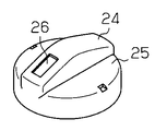
- a rotary switch knob 24 is fixed to the upper end of the switch shaft 17.
- the rotary switch knob 24 includes a knob body 25 and a light guide 26.
- the knob body 25 is provided with a through hole extending along the axis of the rotary switch knob 24.
- the light guide 26 is disposed in the through hole of the knob body 25.
- the upper end surface of the light guide 26 is exposed on the upper surface of the knob body 25.
- the lower end surface of the light guide 26 is exposed on the lower surface of the knob body 25.
- the upper end surface of the light guide 26 indicates the operation position of the rotary switch knob 24.
- a plurality of LEDs 27 are mounted on the illumination board 18.
- the illumination board 18 is covered with a synthetic rubber cover member 28.
- the covering member 28 is formed by two-color molding so as to have a plurality of light transmitting portions 29 that transmit light and a portion that does not transmit light. Each light transmission portion 29 is provided to face the LED 27.
- the light transmitting portion 29 positioned proximal to the switch shaft 17 diffuses and transmits light emitted from the LED 27 positioned proximal to the switch shaft 17.
- the light transmitted through the light transmitting portion 29 located proximal to the switch shaft 17 is incident from the lower end surface of the light guide 26, so that the upper end surface of the light guide 26 emits light.
- a cover 30 made of synthetic resin is fixed to the upper wall of the operation panel body 10.
- the cover 30 is formed with an operation hole 32 and a cylindrical portion 33 extending downward from the periphery of the operation hole 32.
- a lower portion of the rotary switch knob 24 is disposed in the operation hole 32.
- the rotary switch knob 24 is arranged with a gap between it and the inner peripheral surface of the operation hole 32.
- the lower end of the cylindrical portion 33 is formed in a substantially U-shaped cross section so as to have a groove portion 34 extending along the inner peripheral surface of the operation hole 32.
- the bottom wall of the groove portion 34 is in contact with the upper surface of the light transmission portion 29.
- a ring-shaped protrusion 25 a is formed on the lower surface of the knob body 25 along the outer peripheral edge of the knob body 25.
- the protrusion 25a is engaged with the groove 34 with a gap between the protrusion 25a and the inner peripheral surface of the groove 34.
- the groove 34 receives liquid such as drinking water that enters from
- a light transmitting member 35 in the form of letters and symbols indicating the operation position of the rotary switch knob 24 is provided.
- the cover 30 is formed by two-color molding together with the light transmission member 35.
- the light transmission portion 29 located distal to the switch shaft 17 diffuses and transmits light emitted from the LED 27 located distal to the switch shaft 17.
- the light transmitted through the light transmitting portion 29 located distal to the switch shaft 17 enters from the lower end surface of the light transmitting member 35, whereby the upper end surface of the light transmitting member 35 emits light.
- Patent Document 1 discloses an example of a rotary switch.
- a switch body is provided on a switch board.
- a cylindrical portion is provided at the proximal end of the rotary switch.
- the cylindrical portion of the rotary switch is supported so as to be rotatable with respect to the switch main body.
- a movable contact is formed on the outer peripheral surface of the cylindrical portion.
- a fixed contact is provided on the inner peripheral surface of the switch body that supports the tube.
- Patent Document 1 does not specifically disclose a structure for waterproofing.
- An object of the present invention is to provide a waterproof structure for a rotary switch that can prevent liquid from entering the switch board.
- an operation panel body having an upper floor and a lower floor, a switch board disposed on the lower floor, and a support rotatably on the switch board.
- the waterproof structure of the rotary switch having a switch shaft that passes through the shaft hole of the upper floor, a cover that covers the upper floor, and a rotary switch knob that is attached to the switch shaft and rotatably disposed in the operation hole of the cover Is provided.
- An umbrella-shaped portion is formed at the lower part of the rotary switch knob, and the umbrella-shaped portion is disposed between the cover and the upper floor, and the umbrella-shaped portion guides the liquid that has entered the operation hole away from the shaft hole. It is burned.
- the umbrella-shaped portion can guide liquids such as water and drinks that instantaneously enter a large amount from the operation hole so as to be away from the shaft hole. Thereby, the penetration
- an illumination board on which a light emitting element is mounted is provided on the upper floor, and the rotary switch knob is provided on the knob body and an index indicating the operation position of the rotary switch knob.
- the light guide is disposed so as to face the light emitting element, and the umbrella-shaped portion is provided at a lower portion of the light guide.
- the waterproof structure of the rotary switch described above further includes a cover member provided on the illumination board and covering the illumination board, wherein the light emitting element is positioned proximal to the switch shaft and emits light to the light guide.
- a first light-emitting element that emits light, and a second light-emitting element that is positioned distal to the shaft hole on the upper floor, and the covering member includes a first light transmitting portion that transmits light emitted from the first light-emitting element;
- a second light transmitting portion that transmits light emitted from the second light emitting element, and the cover is provided with a third light transmitting portion that transmits light transmitted through the second light transmitting portion.
- the lower part of the light guide is configured and disposed between the second light transmission part and the third light transmission part.
- the umbrella-shaped portion disposed between the second light transmission portion and the third light transmission portion constitutes the lower portion of the light guide, it can transmit light. For this reason, the light emitted from the second light emitting element is transmitted through the second light transmitting portion and the umbrella-shaped portion of the light guide, whereby the third light transmitting portion can emit light.
- a protrusion that prevents liquid from entering the shaft hole on the upper floor is provided on the surface of the cover member that faces the umbrella-shaped portion. According to this configuration, the protrusion can prevent the liquid from entering the shaft hole through the outside of the umbrella-shaped portion, and the waterproofness can be improved.
- the umbrella-shaped portion is provided at a lower portion of the knob body. According to this configuration, it is possible to guide the liquid such as water and drinks that instantaneously enter a large amount from the operation hole so as to be away from the shaft hole by the umbrella-shaped portion. Therefore, it is possible to prevent the liquid from entering the shaft hole and improve the waterproofness.
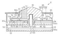
- the top view of the operation panel body by one Embodiment of this invention Sectional drawing of an operation panel body.
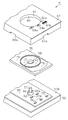
- the exploded perspective view of an operation panel body (A) is a perspective view of a rotary switch knob, (b) is a perspective view of a light guide. Sectional drawing of the conventional operation panel. The perspective view of the conventional rotary switch knob.
- the operation panel P has an operation panel body 50.
- the operation panel body 50 is formed in a rectangular parallelepiped shape from a synthetic resin.
- the bottom wall 50 a of the operation panel body 50 is a lower floor 52, and the upper wall 50 b is an upper floor 54.
- a switch board 56 is fixed to the lower floor 52 in the operation panel body 50.
- An illumination board 58 is fixed to the upper floor 54.
- a shaft cylinder 60 having a shaft hole 60 a protrudes upward from the upper floor 54.
- the illumination board 58 has a through hole 62 through which the shaft cylinder 60 is inserted.
- a switch shaft 57 is rotatably supported on the switch board 56 by a switch body 63. As the switch shaft 57 rotates, the movable contact of the switch body 63 comes into contact with or does not come into contact with the fixed contact of the switch board 56 and is switched on or off. The upper end of the switch shaft 57 penetrates the shaft tube 60 and protrudes upward from the open end of the shaft tube 60. A rotary switch knob 64 is fixed to the upper end of the switch shaft 57.
- a synthetic resin cover 80 is fixed to the upper wall 50b of the operation panel body 50.
- the cover 80 is formed in a covered box shape.
- the cover 80 is formed with an operation hole 81 and a cylindrical portion 82 that extends downward from the periphery of the operation hole 81.
- a plurality of discharge ports 80 a are formed on the side wall of the cover 80.
- a lower portion of the rotary switch knob 64 is disposed in the operation hole 81.
- the rotary switch knob 64 is arranged with a gap between it and the inner peripheral surface of the operation hole 81.
- a plurality of LEDs 74 and 75 as light emitting elements are mounted on the illumination board 58.
- the LED 74 is located proximal to the switch shaft 57.
- the LED 74 corresponds to a first light emitting element.
- the LED 75 is located distal to the switch shaft 57.
- the LED 75 corresponds to a second light emitting element.
- the illumination board 58 is covered with a synthetic rubber covering member 76.
- the covering member 76 is formed by two-color molding so as to have a plurality of light transmitting portions 77 and 78 that transmit light and a light blocking portion 79 that does not transmit light.
- the respective light transmitting portions 77 and 78 are provided so as to face the LEDs 74 and 75, respectively.
- the light transmitting portion 77 is located below the operation hole 81 and is disposed proximal to the switch shaft 57.
- the light transmission part 77 is formed in a substantially semicircular shape.
- the light transmission part 77 corresponds to a first light transmission part.
- the light transmission part 78 is disposed distal to the switch shaft 57 so as to face the light transmission parts 84 a and 84 b of the cover 80.
- the light transmission part 78 has a concave curve having the same diameter as the arc of the light transmission part 77.
- the light transmission part 78 corresponds to a second light transmission part.
- the light blocking portion 79 has a boundary portion that is provided between the light transmitting portion 77 and the light transmitting portion 78 and extends along an arc.
- a ring-shaped protrusion 86 protruding upward is formed on the light blocking portion 79 so as to include a boundary portion between the light transmitting portion 77 and the light transmitting portion 78.
- the light transmission part 77 diffuses and transmits the light emitted from the LED 74.
- the light blocking unit 79 located at the boundary blocks the light diffused by the light transmitting unit 77 from entering the light transmitting unit 78.
- the light transmission part 78 diffuses and transmits the light emitted from the LED 75.
- the light blocking unit 79 located at the boundary blocks the light diffused by the light transmitting unit 78 from entering the light transmitting unit 77.
- a light transmission part 84a in the form of a symbol indicating the operation position of the rotary switch knob 64 and a light transmission part 84b in the form of a letter are provided.
- the cover 80 is two-color molded together with the light transmission portion 84b.
- the light transmission parts 84a and 84b correspond to a third light transmission part.
- the rotary switch knob 64 includes a knob main body 65 and a light guide 66 and is formed by two-color molding. As shown in FIGS. 2 and 4A and 4B, the knob main body 65 has a columnar base 67, a knob portion 68 provided on the upper surface of the base 67, and a fan-shaped flange portion 69. ing.
- the flange portion 69 is provided in the lower portion of the base 67 and is formed in a semicircular ring shape along the outer peripheral edge of the base 67.
- the flange portion 69 corresponds to an umbrella-like portion.
- the light guide 66 is made of a transparent material such as polycarbonate.
- the light guide 66 includes a light guide main body 70 that extends in the vertical direction and a flange portion 72 that is integrally connected to the lower portion of the light guide main body 70.
- the flange portion 72 corresponds to an umbrella-shaped portion.
- the upper end surface of the light guide body 70 is exposed on the upper surface of the knob portion 68.
- the lower end surface of the light guide body 70 is exposed on the lower surface of the base 67.
- the light guide body 70 serves as an index S indicating the operation position of the rotary switch knob 64.
- the switch main body 63 restricts the rotation of the rotary switch knob 64 within a predetermined angle range so that the index S can be selectively switched with respect to the plurality of light transmission portions 84a.
- the flange portion 72 is provided on the opposite side of the flange portion 69 in the lower portion of the base 67.
- the flange portion 72 is formed in a semicircular shape.
- the opposite end surfaces of the flange portion 69 and the flange portion 72 are joined to each other.
- the flange portion 72 is disposed above the light transmitting portion 78 shown in FIG. 3 when the rotary switch knob 64 is rotated within a predetermined angle range.
- the flange part 72 is arrange
- the shape and size of the flange portion 72 are set based on the positional relationship among the LEDs 74 and 75, which are light emitting elements, the light transmission portions 77 and 78, and the light transmission portions 84a and 84b.
- the distance from the axis of the base 67 to the outer peripheral surface of the flange portion 72 is set to be longer than the distance from the axis of the base 67 to the outer peripheral surface of the flange portion 69.
- the distance from the axial center of the base 67 to the outer peripheral surface of the flange portion 72 or the outer peripheral surface of the flange portion 69 may be the same, or may have a reverse relationship to the present embodiment.
- a protrusion 72 a protruding downward is formed on the lower surface of the flange portion 72 along the outer peripheral edge of the flange portion 72.
- a protrusion 69 a protruding downward is formed along the outer peripheral edge of the flange portion 69.
- a part of the liquid may enter the shaft hole 60a from the gap between the flange portions 72 and 69 and the covering member 76.
- the gap between the flange portions 72 and 69 and the covering member 76 is narrowed by the protrusions 72a and 69a, so that liquid can enter the shaft hole 60a. Can be suppressed.
- the ridge 86 of the light blocking portion 79 is further disposed in the cover member 76 at a position closer to the shaft hole 60a than the ridges 72a and 69a.
- flange portions 72 and 69 as umbrella-shaped portions are formed. Both flange portions 72 and 69 are disposed between the cover 80 and the upper floor 54 of the operation panel body 50. According to this configuration, the liquid that has entered the operation hole 81 can be guided by the flange portions 72 and 69 so as to be away from the shaft hole 60a. For this reason, it is possible to prevent liquid such as water and drinks that instantaneously enter a large amount from the operation hole 81 from entering the shaft hole 60a. Therefore, it is possible to prevent liquid from entering the switch substrate 56.
- an illumination board 58 on which LEDs 74 and 75 are mounted is provided on the upper floor 54 of the operation panel body 50.
- the rotary switch knob 64 has a knob body 65 and a light guide 66 serving as an index S.
- the light guide 66 is disposed so as to face the LEDs 74 and 75.
- the flange portion 72 as an umbrella-shaped portion is provided below the light guide 66. According to this configuration, the flange portion 72 can guide the liquid such as water and drinks that instantaneously enter a large amount from the operation hole 81 so as to be away from the shaft hole 60a. Therefore, it is possible to prevent liquid from entering the shaft hole 60a, and it is possible to prevent liquid from entering the switch substrate 16.
- the LED 74 is a first light emitting element that emits light to the light guide, and is located proximal to the switch shaft 57.
- the LED 75 is a second light emitting element and is located distal to the shaft hole 60a.
- the illumination board 58 is covered with a covering member 76.
- the covering member 76 includes a light transmission part 77 that can transmit light emitted from the LED 74 and a light transmission part 78 that can transmit light emitted from the LED 75.
- the cover 80 is provided with light transmitting portions 84 a and 84 b that transmit light transmitted through the light transmitting portion 78.
- the flange portion 72 is disposed between the light transmission portion 78 and the light transmission portions 84a and 84b.
- the flange portion 72 of the light guide 66 transmits light, the light emitted from the LED 75 passes through the light transmission portion 78 and the flange portion 72 of the light guide 66, whereby the light transmission portions 84a, 84a, 84b can emit light.
- a protrusion 86 is provided on the surface of the covering member 76 facing the flange portions 72 and 69. For this reason, the protrusion 86 can prevent liquid from entering the shaft hole 60 a through the outside of the flange portions 72 and 69, and can prevent liquid from entering the switch substrate 56.
- a flange portion 69 is provided at the lower portion of the knob body 65. According to this configuration, the flange portion 69 can guide the liquid such as water and drinks that instantaneously enter a large amount from the operation hole 81 so as to be away from the shaft hole 60a. For this reason, it is possible to prevent the liquid from entering the shaft hole 60a, and it is possible to prevent the liquid from entering the switch substrate 56.
- the flange portion 69 may be omitted.
- the flange portion 72 of the light guide 66 may be formed in a circular shape so as to protrude in the radial direction from the lower portion of the base 67.
- the illumination substrate 58, the covering member 76, the light transmission parts 84a and 84b, the light guide 66, and the flange part 72 may be omitted.
- the flange portion 69 of the rotary switch knob 64 may be formed on the entire periphery of the knob body 65 at the lower portion of the knob body 65.
- the protrusions 69a and 72a may be omitted.
- the protrusion 86 may be omitted.
Landscapes
- Rotary Switch, Piano Key Switch, And Lever Switch (AREA)
Abstract
La présente invention concerne un bouton de commutateur rotatif (64) dans lequel un rebord (72) est disposé sur la partie inférieure d'un guide de lumière (66), et un rebord (69) est disposé sur la partie inférieure d'un corps de bouton (65). Les deux rebords (72, 69) sont disposés entre un couvercle (80) d'un panneau d'éclairage (58) et un niveau supérieur (54) d'un corps de panneau de commande (50). Les rebords (72, 69) amènent un fluide ayant pénétré à travers un trou de commande (81) à être guidé pour s'éloigner d'un trou d'arbre (60a).
Priority Applications (2)
| Application Number | Priority Date | Filing Date | Title |
|---|---|---|---|
| PCT/JP2011/053053 WO2012111075A1 (fr) | 2011-02-14 | 2011-02-14 | Structure imperméable de commutateur rotatif |
| JP2012541673A JP5447688B2 (ja) | 2011-02-14 | 2011-02-14 | ロータリスイッチの防水構造 |
Applications Claiming Priority (1)
| Application Number | Priority Date | Filing Date | Title |
|---|---|---|---|
| PCT/JP2011/053053 WO2012111075A1 (fr) | 2011-02-14 | 2011-02-14 | Structure imperméable de commutateur rotatif |
Publications (1)
| Publication Number | Publication Date |
|---|---|
| WO2012111075A1 true WO2012111075A1 (fr) | 2012-08-23 |
Family
ID=46672040
Family Applications (1)
| Application Number | Title | Priority Date | Filing Date |
|---|---|---|---|
| PCT/JP2011/053053 Ceased WO2012111075A1 (fr) | 2011-02-14 | 2011-02-14 | Structure imperméable de commutateur rotatif |
Country Status (2)
| Country | Link |
|---|---|
| JP (1) | JP5447688B2 (fr) |
| WO (1) | WO2012111075A1 (fr) |
Cited By (6)
| Publication number | Priority date | Publication date | Assignee | Title |
|---|---|---|---|---|
| JP2013130668A (ja) * | 2011-12-21 | 2013-07-04 | Canon Inc | 電子機器 |
| JP2015106514A (ja) * | 2013-11-29 | 2015-06-08 | 帝国通信工業株式会社 | 照光機構付き回転式電子部品の防滴構造 |
| WO2015174092A1 (fr) * | 2014-05-15 | 2015-11-19 | パナソニックIpマネジメント株式会社 | Bouton de commande et dispositif d'affichage muni de ce bouton |
| JP2019041580A (ja) * | 2015-02-13 | 2019-03-14 | 株式会社マキタ | 発光表示部 |
| US20190285281A1 (en) * | 2018-03-16 | 2019-09-19 | Haier Us Appliance Solutions, Inc. | Ignition switch assembly for a cooktop appliance |
| JP7664807B2 (ja) | 2021-10-22 | 2025-04-18 | 株式会社東海理化電機製作所 | 電子機器 |
Families Citing this family (2)
| Publication number | Priority date | Publication date | Assignee | Title |
|---|---|---|---|---|
| KR102491253B1 (ko) * | 2016-08-31 | 2023-01-26 | 주식회사 위니아 | 전기밥솥 |
| CN112455178A (zh) * | 2020-11-09 | 2021-03-09 | 杭州广安汽车电器有限公司 | 一种旋钮防水的空调控制器结构 |
Citations (6)
| Publication number | Priority date | Publication date | Assignee | Title |
|---|---|---|---|---|
| JP2000037596A (ja) * | 1998-07-21 | 2000-02-08 | Toshiba Corp | 洗濯機 |
| JP2006066232A (ja) * | 2004-08-26 | 2006-03-09 | Sansha Electric Mfg Co Ltd | 電源装置の液侵入防止のための防滴構造 |
| JP2007012609A (ja) * | 2005-06-28 | 2007-01-18 | Tektronix Inc | 電子機器及びそのノブ |
| JP2007188760A (ja) * | 2006-01-13 | 2007-07-26 | Matsushita Electric Ind Co Ltd | 電気機器 |
| JP2008132917A (ja) * | 2006-11-29 | 2008-06-12 | Kojima Press Co Ltd | 車両用コントロールパネル |
| JP2010108801A (ja) * | 2008-10-31 | 2010-05-13 | Kenwood Corp | 回転操作軸の防水構造 |
-
2011
- 2011-02-14 WO PCT/JP2011/053053 patent/WO2012111075A1/fr not_active Ceased
- 2011-02-14 JP JP2012541673A patent/JP5447688B2/ja not_active Expired - Fee Related
Patent Citations (6)
| Publication number | Priority date | Publication date | Assignee | Title |
|---|---|---|---|---|
| JP2000037596A (ja) * | 1998-07-21 | 2000-02-08 | Toshiba Corp | 洗濯機 |
| JP2006066232A (ja) * | 2004-08-26 | 2006-03-09 | Sansha Electric Mfg Co Ltd | 電源装置の液侵入防止のための防滴構造 |
| JP2007012609A (ja) * | 2005-06-28 | 2007-01-18 | Tektronix Inc | 電子機器及びそのノブ |
| JP2007188760A (ja) * | 2006-01-13 | 2007-07-26 | Matsushita Electric Ind Co Ltd | 電気機器 |
| JP2008132917A (ja) * | 2006-11-29 | 2008-06-12 | Kojima Press Co Ltd | 車両用コントロールパネル |
| JP2010108801A (ja) * | 2008-10-31 | 2010-05-13 | Kenwood Corp | 回転操作軸の防水構造 |
Cited By (8)
| Publication number | Priority date | Publication date | Assignee | Title |
|---|---|---|---|---|
| JP2013130668A (ja) * | 2011-12-21 | 2013-07-04 | Canon Inc | 電子機器 |
| JP2015106514A (ja) * | 2013-11-29 | 2015-06-08 | 帝国通信工業株式会社 | 照光機構付き回転式電子部品の防滴構造 |
| WO2015174092A1 (fr) * | 2014-05-15 | 2015-11-19 | パナソニックIpマネジメント株式会社 | Bouton de commande et dispositif d'affichage muni de ce bouton |
| JPWO2015174092A1 (ja) * | 2014-05-15 | 2017-04-20 | パナソニックIpマネジメント株式会社 | 操作つまみおよびそれを利用した表示装置 |
| US10318078B2 (en) | 2014-05-15 | 2019-06-11 | Panasonic Intellectual Property Management Co., Ltd. | Operation knob and display device in which same is used |
| JP2019041580A (ja) * | 2015-02-13 | 2019-03-14 | 株式会社マキタ | 発光表示部 |
| US20190285281A1 (en) * | 2018-03-16 | 2019-09-19 | Haier Us Appliance Solutions, Inc. | Ignition switch assembly for a cooktop appliance |
| JP7664807B2 (ja) | 2021-10-22 | 2025-04-18 | 株式会社東海理化電機製作所 | 電子機器 |
Also Published As
| Publication number | Publication date |
|---|---|
| JPWO2012111075A1 (ja) | 2014-07-03 |
| JP5447688B2 (ja) | 2014-03-19 |
Similar Documents
| Publication | Publication Date | Title |
|---|---|---|
| JP5447688B2 (ja) | ロータリスイッチの防水構造 | |
| JP6734426B2 (ja) | 表示灯 | |
| CN102782790B (zh) | 操作装置 | |
| JP5986430B2 (ja) | 照光表示スイッチ装置 | |
| US7780325B2 (en) | Luminous turning button | |
| US9557014B2 (en) | Signal indicator lamp | |
| JP2009069314A (ja) | 表示装置 | |
| JP2008192558A (ja) | 車載用ノブスイッチ | |
| JP6244331B2 (ja) | 多方向スイッチ装置 | |
| JP2006190597A (ja) | 点灯装置 | |
| KR20170001927U (ko) | 면조명 장치 | |
| JP4855872B2 (ja) | ノブ型表示装置 | |
| JP2008047421A (ja) | 操作装置 | |
| JP6241922B2 (ja) | 灯器 | |
| KR101722171B1 (ko) | 차량용 포인터 | |
| JP6478216B2 (ja) | 照明装置及び車両用照明装置 | |
| JP6195498B2 (ja) | 灯器用光源ユニット | |
| JP6126704B2 (ja) | 可動部付電子部品 | |
| WO2018214329A1 (fr) | Bouton lumineux et couvercle de toilettes de lavage | |
| JP5561000B2 (ja) | 発光指針 | |
| CN207977262U (zh) | 防止底部漏光的旋钮开关 | |
| JP7489209B2 (ja) | 操作装置 | |
| JP7136677B2 (ja) | 操作装置 | |
| JP4708281B2 (ja) | 車内用インジケータの照明装置 | |
| JP2010175365A (ja) | 照明装置 |
Legal Events
| Date | Code | Title | Description |
|---|---|---|---|
| WWE | Wipo information: entry into national phase |
Ref document number: 2012541673 Country of ref document: JP |
|
| 121 | Ep: the epo has been informed by wipo that ep was designated in this application |
Ref document number: 11858552 Country of ref document: EP Kind code of ref document: A1 |
|
| NENP | Non-entry into the national phase |
Ref country code: DE |
|
| 122 | Ep: pct application non-entry in european phase |
Ref document number: 11858552 Country of ref document: EP Kind code of ref document: A1 |