WO2012111161A1 - Pile secondaire au lithium-ion et son procédé de fabrication - Google Patents
Pile secondaire au lithium-ion et son procédé de fabrication Download PDFInfo
- Publication number
- WO2012111161A1 WO2012111161A1 PCT/JP2011/053570 JP2011053570W WO2012111161A1 WO 2012111161 A1 WO2012111161 A1 WO 2012111161A1 JP 2011053570 W JP2011053570 W JP 2011053570W WO 2012111161 A1 WO2012111161 A1 WO 2012111161A1
- Authority
- WO
- WIPO (PCT)
- Prior art keywords
- negative electrode
- current collector
- composition
- magnetic field
- electrode current
- Prior art date
- Legal status (The legal status is an assumption and is not a legal conclusion. Google has not performed a legal analysis and makes no representation as to the accuracy of the status listed.)
- Ceased
Links
Images


Classifications
-
- H—ELECTRICITY
- H01—ELECTRIC ELEMENTS
- H01M—PROCESSES OR MEANS, e.g. BATTERIES, FOR THE DIRECT CONVERSION OF CHEMICAL ENERGY INTO ELECTRICAL ENERGY
- H01M10/00—Secondary cells; Manufacture thereof
- H01M10/04—Construction or manufacture in general
- H01M10/0431—Cells with wound or folded electrodes
-
- H—ELECTRICITY
- H01—ELECTRIC ELEMENTS
- H01M—PROCESSES OR MEANS, e.g. BATTERIES, FOR THE DIRECT CONVERSION OF CHEMICAL ENERGY INTO ELECTRICAL ENERGY
- H01M4/00—Electrodes
- H01M4/02—Electrodes composed of, or comprising, active material
- H01M4/13—Electrodes for accumulators with non-aqueous electrolyte, e.g. for lithium-accumulators; Processes of manufacture thereof
- H01M4/133—Electrodes based on carbonaceous material, e.g. graphite-intercalation compounds or CFx
-
- H—ELECTRICITY
- H01—ELECTRIC ELEMENTS
- H01M—PROCESSES OR MEANS, e.g. BATTERIES, FOR THE DIRECT CONVERSION OF CHEMICAL ENERGY INTO ELECTRICAL ENERGY
- H01M4/00—Electrodes
- H01M4/02—Electrodes composed of, or comprising, active material
- H01M4/04—Processes of manufacture in general
-
- H—ELECTRICITY
- H01—ELECTRIC ELEMENTS
- H01M—PROCESSES OR MEANS, e.g. BATTERIES, FOR THE DIRECT CONVERSION OF CHEMICAL ENERGY INTO ELECTRICAL ENERGY
- H01M10/00—Secondary cells; Manufacture thereof
- H01M10/05—Accumulators with non-aqueous electrolyte
-
- H—ELECTRICITY
- H01—ELECTRIC ELEMENTS
- H01M—PROCESSES OR MEANS, e.g. BATTERIES, FOR THE DIRECT CONVERSION OF CHEMICAL ENERGY INTO ELECTRICAL ENERGY
- H01M10/00—Secondary cells; Manufacture thereof
- H01M10/05—Accumulators with non-aqueous electrolyte
- H01M10/052—Li-accumulators
- H01M10/0525—Rocking-chair batteries, i.e. batteries with lithium insertion or intercalation in both electrodes; Lithium-ion batteries
-
- H—ELECTRICITY
- H01—ELECTRIC ELEMENTS
- H01M—PROCESSES OR MEANS, e.g. BATTERIES, FOR THE DIRECT CONVERSION OF CHEMICAL ENERGY INTO ELECTRICAL ENERGY
- H01M10/00—Secondary cells; Manufacture thereof
- H01M10/05—Accumulators with non-aqueous electrolyte
- H01M10/058—Construction or manufacture
- H01M10/0587—Construction or manufacture of accumulators having only wound construction elements, i.e. wound positive electrodes, wound negative electrodes and wound separators
-
- H—ELECTRICITY
- H01—ELECTRIC ELEMENTS
- H01M—PROCESSES OR MEANS, e.g. BATTERIES, FOR THE DIRECT CONVERSION OF CHEMICAL ENERGY INTO ELECTRICAL ENERGY
- H01M4/00—Electrodes
- H01M4/02—Electrodes composed of, or comprising, active material
- H01M4/13—Electrodes for accumulators with non-aqueous electrolyte, e.g. for lithium-accumulators; Processes of manufacture thereof
- H01M4/139—Processes of manufacture
- H01M4/1393—Processes of manufacture of electrodes based on carbonaceous material, e.g. graphite-intercalation compounds or CFx
-
- H—ELECTRICITY
- H01—ELECTRIC ELEMENTS
- H01M—PROCESSES OR MEANS, e.g. BATTERIES, FOR THE DIRECT CONVERSION OF CHEMICAL ENERGY INTO ELECTRICAL ENERGY
- H01M4/00—Electrodes
- H01M4/02—Electrodes composed of, or comprising, active material
- H01M4/36—Selection of substances as active materials, active masses, active liquids
- H01M4/58—Selection of substances as active materials, active masses, active liquids of inorganic compounds other than oxides or hydroxides, e.g. sulfides, selenides, tellurides, halogenides or LiCoFy; of polyanionic structures, e.g. phosphates, silicates or borates
- H01M4/583—Carbonaceous material, e.g. graphite-intercalation compounds or CFx
- H01M4/587—Carbonaceous material, e.g. graphite-intercalation compounds or CFx for inserting or intercalating light metals
-
- H—ELECTRICITY
- H01—ELECTRIC ELEMENTS
- H01M—PROCESSES OR MEANS, e.g. BATTERIES, FOR THE DIRECT CONVERSION OF CHEMICAL ENERGY INTO ELECTRICAL ENERGY
- H01M4/00—Electrodes
- H01M4/02—Electrodes composed of, or comprising, active material
- H01M2004/021—Physical characteristics, e.g. porosity, surface area
-
- Y—GENERAL TAGGING OF NEW TECHNOLOGICAL DEVELOPMENTS; GENERAL TAGGING OF CROSS-SECTIONAL TECHNOLOGIES SPANNING OVER SEVERAL SECTIONS OF THE IPC; TECHNICAL SUBJECTS COVERED BY FORMER USPC CROSS-REFERENCE ART COLLECTIONS [XRACs] AND DIGESTS
- Y02—TECHNOLOGIES OR APPLICATIONS FOR MITIGATION OR ADAPTATION AGAINST CLIMATE CHANGE
- Y02E—REDUCTION OF GREENHOUSE GAS [GHG] EMISSIONS, RELATED TO ENERGY GENERATION, TRANSMISSION OR DISTRIBUTION
- Y02E60/00—Enabling technologies; Technologies with a potential or indirect contribution to GHG emissions mitigation
- Y02E60/10—Energy storage using batteries
-
- Y—GENERAL TAGGING OF NEW TECHNOLOGICAL DEVELOPMENTS; GENERAL TAGGING OF CROSS-SECTIONAL TECHNOLOGIES SPANNING OVER SEVERAL SECTIONS OF THE IPC; TECHNICAL SUBJECTS COVERED BY FORMER USPC CROSS-REFERENCE ART COLLECTIONS [XRACs] AND DIGESTS
- Y02—TECHNOLOGIES OR APPLICATIONS FOR MITIGATION OR ADAPTATION AGAINST CLIMATE CHANGE
- Y02P—CLIMATE CHANGE MITIGATION TECHNOLOGIES IN THE PRODUCTION OR PROCESSING OF GOODS
- Y02P70/00—Climate change mitigation technologies in the production process for final industrial or consumer products
- Y02P70/50—Manufacturing or production processes characterised by the final manufactured product
-
- Y—GENERAL TAGGING OF NEW TECHNOLOGICAL DEVELOPMENTS; GENERAL TAGGING OF CROSS-SECTIONAL TECHNOLOGIES SPANNING OVER SEVERAL SECTIONS OF THE IPC; TECHNICAL SUBJECTS COVERED BY FORMER USPC CROSS-REFERENCE ART COLLECTIONS [XRACs] AND DIGESTS
- Y02—TECHNOLOGIES OR APPLICATIONS FOR MITIGATION OR ADAPTATION AGAINST CLIMATE CHANGE
- Y02T—CLIMATE CHANGE MITIGATION TECHNOLOGIES RELATED TO TRANSPORTATION
- Y02T10/00—Road transport of goods or passengers
- Y02T10/60—Other road transportation technologies with climate change mitigation effect
- Y02T10/70—Energy storage systems for electromobility, e.g. batteries
Definitions
- the present invention relates to a lithium ion secondary battery and a manufacturing method thereof.
- the present invention relates to a structure of a negative electrode for a lithium ion secondary battery suitable for being used as a power source for vehicles and a method for forming the structure.
- a lithium ion secondary battery includes a positive electrode and a negative electrode, and an electrolytic solution interposed between the two electrodes. Lithium ions pass between the positive electrode and the negative electrode through an electrolytic solution containing an electrolyte such as a lithium salt. Charge and discharge by going back and forth.
- a typical negative electrode of this type of lithium ion secondary battery includes a negative electrode active material capable of reversibly occluding and releasing lithium ions. Examples of the negative electrode active material include various carbon materials, and for example, a graphite material is used. Graphite has a layered crystal structure, and charge and discharge are realized by occlusion of lithium ions between the layers (interlayers) and release of lithium ions from the layers.
- the paste-like composition includes a slurry-like composition and an ink-like composition.
- the paste-like composition is simply referred to as “composition”.
- graphite When graphite is applied to the current collector to form the negative electrode, graphite has a property that the layer surface ((002) surface) of the graphite is easily arranged in parallel to the surface (wide surface) of the current collector. have. For this reason, the edge of graphite (the end of the plurality of layers) is arranged approximately parallel to the current collector, so that lithium ions can be occluded into and discharged from the layers during charging and discharging. There is a risk of not being done.
- Patent Document 1 is cited as a prior art.
- Patent Document 1 describes a technique in which a magnetic field is applied to the composition so that the layer surface of graphite is arranged perpendicular to the current collector.
- Patent Document 2 is cited as a conventional technique related to a negative electrode for a lithium ion secondary battery.
- the layer surface of graphite in the negative electrode (that is, the (002) surface which is a plane parallel to the graphite layer) can be arranged perpendicular to the current collector.
- the layer surface of each graphite is arranged irregularly (multidirectional) with respect to the long current collector. For this reason, when the graphite contracts during discharge of the lithium ion secondary battery including the wound electrode body including the elongated negative electrode, an electrolyte (electrolyte) such as a lithium salt in the graphite is used as the electrode body.
- the negative electrode (electrode body) flows in the direction of the winding axis and flows out of the negative electrode (electrode body), and the internal resistance of the negative electrode (electrode body) may increase due to a decrease in the electrolyte in the negative electrode (electrode body). Therefore, the present invention was created to solve the above-described conventional problems, and its purpose is to prevent the electrolyte such as lithium salt from flowing out of the negative electrode during the discharge of the lithium ion secondary battery.
- a lithium ion secondary battery capable of suppressing an increase in internal resistance and a method for manufacturing the secondary battery are provided.
- the present invention provides a lithium ion secondary battery comprising a wound electrode body in which a positive electrode and a negative electrode are wound through a separator, and an electrolytic solution.
- the negative electrode includes a long negative electrode current collector and a negative electrode mixture layer including at least a graphite material formed on the surface of the negative electrode current collector. ing. At least 50% by mass of the graphite material in the negative electrode mixture layer is such that the (002) surface of the graphite material is perpendicular to the surface (wide surface) of the negative electrode current collector and the elongated negative electrode current collector It arrange
- the “(002) plane of the graphite material” is a layer surface (plane parallel to the graphite layer) of the graphite material (graphite crystal) having a layered structure, and the carbon of the graphene sheet constituting the graphite material This refers to the horizontal plane with the network.
- the lithium ion secondary battery provided by the present invention includes a negative electrode mixture layer containing a graphite material, and is at least 50 mass% (for example, 70 mass% or more, preferably 80 mass% or more, more preferably) of the graphite material. Is 90 mass% or more.)
- the graphite material is arranged (arranged) so that its (002) plane is perpendicular to the surface of the negative electrode current collector and parallel to the longitudinal direction of the negative electrode current collector. As described above, since the (002) plane of the graphite material is arranged in the predetermined direction in the negative electrode mixture layer of the negative electrode, the graphite material shrinks during the discharge of the lithium ion secondary battery.
- the electrolyte such as lithium salt present in the metal moves from the graphite material
- the electrolyte moves in the longitudinal direction of the negative electrode (negative electrode current collector) and the movement in the width direction (winding axis direction) is suppressed. Therefore, it is possible to effectively prevent the electrolyte from flowing out of the negative electrode. For this reason, an increase in internal resistance due to the outflow of an electrolyte such as a lithium salt can be suppressed.
- the graphite material it is particularly meaningful to use a graphite material having a median diameter (D 50 ) of 5 ⁇ m to 20 ⁇ m in the particle size distribution measured based on the laser diffraction scattering method.
- a positive electrode in which a positive electrode mixture layer is formed on a positive electrode current collector and a negative electrode in which a negative electrode mixture layer is formed on a negative electrode current collector are separators.
- a method of manufacturing a lithium ion secondary battery comprising a wound electrode body wound through a battery and an electrolytic solution. That is, the lithium ion secondary battery manufacturing method disclosed herein prepares a paste-like composition for forming a negative electrode mixture layer obtained by mixing at least a graphite material and a predetermined solvent and kneading the mixture.
- the direction is perpendicular to the longitudinal direction of the elongated negative electrode current collector, from one long side of the negative electrode current collector to the other long side.
- a magnetic field in which magnetic lines of force are generated in the width direction of the current collector defined as a direction in which the current flows is applied, and then a current collector orthogonal direction in which the direction of the magnetic field lines is defined as a direction orthogonal to the surface of the negative electrode current collector
- the (002) plane of the graphite material contained in the composition is changed to the surface of the negative electrode current collector.
- the graphite material is displaced so as to be orthogonal and parallel to the longitudinal direction of the negative electrode current collector.
- “to change the direction of the magnetic lines of force continuously” includes changing the direction of the magnetic lines of force continuously from one direction to another target in a stepless manner. From one direction to another target direction is included.
- a long negative electrode current collector is obtained by continuously changing the magnetic field so that the direction of the magnetic lines of force changes from the current collector width direction to the current collector orthogonal direction.
- At least 50% by mass (for example, 70% by mass or more, preferably 80% by mass or more, more preferably 90% by mass or more) of the graphite material contained in the composition coated on the electric conductor is (002).
- Surface is perpendicular to the surface (wide surface) of the negative electrode current collector and parallel to the longitudinal direction of the negative electrode current collector.
- the composition is applied to the surface of the moving negative electrode current collector while moving the elongated negative electrode current collector in a predetermined direction. This is done by applying the composition continuously.
- the application of a magnetic field to the applied composition is a magnetic field generator disposed along the negative electrode current collector after application of the composition that moves in the predetermined direction. Including that the magnetic field lines are continuously changed from the current collector width direction to the current collector orthogonal direction from the upstream side toward the downstream side. According to this configuration, a negative electrode including a negative electrode mixture layer in which graphite materials are regularly arranged can be continuously manufactured.
- the magnetic field generator has a magnetic field line extending from the current collector width direction to the current collector orthogonally from the upstream side to the downstream side of the negative electrode current collector. It is a plurality of magnets or a plurality of coils that are arranged at different angles so as to change in direction. According to this configuration, by using a plurality of magnets or coils as the magnetic field generator, a negative electrode including a negative electrode mixture layer in which graphite materials are regularly arranged can be easily manufactured.
- the solid content of the composition when the total amount of the composition is 100% by mass, the solid content of the composition is 40% by mass to 55% by mass.
- the (002) plane of the graphite material in the composition when a magnetic field is applied to the composition applied to the negative electrode current collector, the (002) plane of the graphite material in the composition is orthogonal to the surface of the negative electrode current collector and the negative electrode current collector. It becomes easy to displace so that it may become parallel to the longitudinal direction of an electric body.
- the negative electrode mixture layer when the negative electrode mixture layer is formed, the negative electrode mixture layer is applied in a state in which a magnetic field having magnetic lines of force directed in the direction perpendicular to the current collector is applied to the composition. Allow the composition to dry.
- the (002) plane of the graphite material in the negative electrode mixture layer is more reliably perpendicular to the surface of the negative electrode current collector and the negative electrode current collector Can be parallel to the longitudinal direction.
- the present invention provides a vehicle (typically, an automobile, particularly a hybrid automobile, an electric automobile, a fuel cell automobile, etc.) having such a secondary battery (may be an assembled battery formed by connecting a plurality of batteries in series) as a power source.
- a motor vehicle equipped with a simple electric motor may be an assembled battery formed by connecting a plurality of batteries in series.
- FIG. 1 is a perspective view schematically showing the outer shape of a lithium ion secondary battery according to an embodiment of the present invention.
- 2 is a cross-sectional view taken along line II-II in FIG.
- FIG. 3 is a cross-sectional view schematically showing the structure of the electrode body of the lithium ion secondary battery according to one embodiment of the present invention.
- FIG. 4 is a flowchart for explaining a method of manufacturing a lithium ion secondary battery according to an embodiment of the present invention.
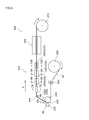
- FIG. 5 is an explanatory view schematically showing a schematic configuration of a negative electrode manufacturing apparatus according to an embodiment of the present invention.
- FIG. 6A is a plan view schematically showing the structure of the negative electrode in the intermediate manufacturing process in the negative electrode manufacturing method according to one embodiment of the present invention.
- FIG. 6B is a cross-sectional view taken along line 6B-6B in FIG.
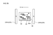
- FIG. 7A is a plan view schematically showing the structure of a negative electrode in the course of manufacturing in the negative electrode manufacturing method according to one embodiment of the present invention.
- 7B is a cross-sectional view taken along line 7B-7B in FIG.
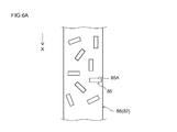
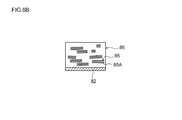
- FIG. 8A is a plan view schematically showing the structure of the negative electrode in the intermediate manufacturing process in the negative electrode manufacturing method according to one embodiment of the present invention.
- 8B is a cross-sectional view taken along line 8B-8B in FIG.
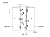
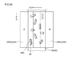
- FIG. 9A is a plan view schematically showing the structure of the negative electrode in the intermediate manufacturing process in the negative electrode manufacturing method according to one embodiment of the present invention.
- FIG. 9B is a cross-sectional view taken along line 9B-9B in FIG.
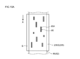
- FIG. 10A is a plan view schematically showing the structure of the negative electrode during the production intermediate stage in the method for producing a negative electrode according to one embodiment of the present invention.
- 10B is a cross-sectional view taken along line 10B-10B in FIG.
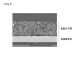
- FIG. 11 is a cross-sectional SEM image of the negative electrode sheet according to Example 1.
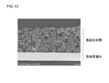
- FIG. 12 is a cross-sectional SEM image of the negative electrode sheet according to Comparative Example 1.
- FIG. 13 is a cross-sectional SEM image of the negative electrode sheet according to Comparative Example 2.
- FIG. 14 is a graph showing the relationship between the IV resistance and the number of cycles.
- FIG. 15 is a side view schematically showing a vehicle (automobile) provided with the lithium ion secondary battery according to the present invention.
- FIG. 16A is a plan view schematically showing the structure of the negative electrode in the intermediate production step in the conventional negative electrode production method.
- FIG. 16B is a cross-sectional view schematically showing the structure of the negative electrode manufactured by the conventional negative electrode manufacturing method.
- the manufacturing method of the lithium ion secondary battery disclosed here includes a composition preparation step (step S10), a composition application step (step S20), and a magnetic field application step (step S30). And a drying process (step S40).
- FIG. 5 is a diagram showing a manufacturing apparatus that embodies a method for manufacturing a negative electrode used in such a lithium ion secondary battery.
- the negative electrode manufacturing apparatus 200 according to the present embodiment roughly includes a supply roll 205, a composition application unit 220, a magnetic field application unit 230, a drying furnace 250, and a recovery roll 210.
- the negative electrode current collector 82 is guided by a guide 240 that is supplied from the supply roll 205 and can travel along a predetermined route, and is collected by the collection roll 210 through the above steps.
- composition preparation step (S10) there may be a paste-like composition for forming a negative electrode mixture layer (hereinafter simply referred to as “paste”) obtained by mixing at least a graphite material and a predetermined solvent and kneading the mixture. ) Is included.
- a paste is prepared by dispersing a graphite material and a binder (binder) in a predetermined solvent.
- Examples of the graphite material include natural graphite and artificial graphite (artificial graphite) capable of reversibly occluding and releasing lithium ions.
- the median diameter (D 50 ) in the particle size distribution measured based on the laser diffraction scattering method of the graphite material is preferably about 5 ⁇ m to 20 ⁇ m. When the median diameter is too larger than 20 ⁇ m, the effective capacity of the negative electrode may be reduced due to the time required for diffusion of lithium ions into the center of the graphite material. If the median diameter is too smaller than 5 ⁇ m, the side reaction rate on the surface of the graphite material increases, and the irreversible capacity of the lithium ion secondary battery may increase.
- the thing similar to the binder used for the negative electrode of a general lithium ion secondary battery can be employ
- a polymer material that dissolves or disperses in water can be preferably used as the binder.
- Cellulose polymers such as carboxymethylcellulose (CMC), methylcellulose (MC), cellulose acetate phthalate (CAP), hydroxypropylmethylcellulose (HPMC), etc .; polyvinyl alcohol (PVA) And the like are exemplified.
- polymer materials that are dispersed in water include fluorine resins such as polytetrafluoroethylene (PTFE); vinyl acetate copolymers; rubbers such as styrene butadiene rubber (SBR);
- PTFE polytetrafluoroethylene
- SBR styrene butadiene rubber
- the polymer material exemplified above can be used for the purpose of exhibiting the function as a thickener or other additive of the composition in addition to the function as a binder.
- the “aqueous composition” is a concept indicating a composition using water or a mixed solvent mainly composed of water (aqueous solvent) as the predetermined solvent (dispersion medium).
- aqueous solvent mainly composed of water (aqueous solvent) as the predetermined solvent (dispersion medium).
- the solvent other than water constituting the mixed solvent one or more organic solvents (lower alcohol, lower ketone, etc.) that can be uniformly mixed with water can be appropriately selected and used.
- the operation of mixing (kneading) the graphite material and the binder in a solvent can be performed using, for example, a suitable kneader (planetary mixer, homodisper, clear mix, fill mix, etc.).
- a suitable kneader planetary mixer, homodisper, clear mix, fill mix, etc.
- the graphite material, the binder, and a small amount of solvent are kneaded, and then the obtained kneaded material may be diluted with an appropriate amount of solvent.
- the solid content of the paste-like composition is about 30% to 65% by mass, and preferably about 40% to 55% by mass.
- the ratio of the graphite material to the total solid content of the composition is about 80% by mass to 100% by mass, and preferably about 95% by mass to 100% by mass.
- the ratio of the binder to the entire solid content of the composition can be, for example, about 0.1% by mass to 5% by mass, and usually about 0.1% by mass to 3% by mass. Is preferred.
- the proportion of the thickener in the total solid content of the composition can be, for example, about 0.1% by mass to 5% by mass, and usually about 0.1% by mass to It is preferable to set it as 3 mass%.
- the composition coating step includes coating the prepared composition on the surface of the long negative electrode current collector.
- the composition application unit 220 is a die coater.
- the prepared composition 86 is supplied to the die 222 of the composition application unit 220, and the composition 86 is applied to the surface of the long negative electrode current collector 82 fed from the supply roll 205.
- a conductive member made of a metal having good conductivity is preferably used, like the current collector used in the negative electrode of a conventional lithium ion secondary battery.
- a copper material, a nickel material, or a long sheet-shaped alloy material mainly composed of them can be used.
- the thickness of the sheet-shaped negative electrode current collector 82 is about 10 ⁇ m to 30 ⁇ m.
- the composition application unit 220 of the negative electrode manufacturing apparatus 200 of the present embodiment is a die coater, but is not limited thereto, and the application of the composition 86 to the negative electrode current collector 82 is a conventional general lithium ion. This can be performed in the same manner as in the case of producing an electrode (negative electrode) for a secondary battery.
- a conventionally known appropriate coating apparatus such as a slit coater, a comma coater, a gravure coater or the like can be used instead.
- the magnetic field application step includes applying a magnetic field to the applied composition (a composition in which the solvent remains and is not dried).
- the application of the magnetic field is defined as a direction perpendicular to the longitudinal direction of the long negative electrode current collector and from one long side to the other long side of the negative electrode current collector.
- a magnetic field in which magnetic field lines are generated in the width direction of the current collector is applied, and then the magnetic field in which the direction of the magnetic field lines is in a direction orthogonal to the current collector, which is defined as a direction perpendicular to the surface (wide surface) of the negative electrode current collector Is carried out by continuously changing the direction of the magnetic lines of force until a state of applying a magnetic field is reached.
- the magnetic field application unit 230 in the negative electrode manufacturing apparatus 200 includes a plurality of pairs of magnetic field generators 235 arranged to face each other with the negative electrode current collector 82 interposed therebetween.
- the magnetic field generator 235 is not particularly limited as long as it can generate a magnetic field, and examples thereof include a permanent magnet and an electromagnetic coil.
- the direction of the magnetic lines of force changes from the current collector width direction to the current collector orthogonal direction.
- Magnetic field generators 235A, 235B, 235C, and 235D are respectively arranged at different angles. That is, as shown in FIG. 7A and FIG. 7B, the pair of magnetic field generators 235A has a length of the negative electrode current collector 82 such that the wide surface of the magnetic field generator 235A and the wide surface of the negative electrode current collector 82 are parallel. Arranged along the direction (direction of arrow X). By arranging the magnetic field generator 235A in this way, the composition 86 applied to the surface of the negative electrode current collector 82 is in a direction perpendicular to the longitudinal direction of the long negative electrode current collector 82.
- a magnetic field in which magnetic lines of force are generated in the current collector width direction (the direction of arrow Y1 shown in FIGS. 7A and 7B) defined as a direction from one long side to the other long side of the negative electrode current collector 82. Can be applied.
- the angle formed by the wide surface of the magnetic field generator 235B and the wide surface of the negative electrode current collector 82 is ⁇ A (for example, about 20 degrees to about 20 degrees). It is disposed along the longitudinal direction of the negative electrode current collector 82 (the direction of the arrow X) so as to be 40 degrees, 30 degrees in this embodiment.
- the angle formed by the wide surface of the magnetic field generator 235C and the wide surface of the negative electrode current collector 82 is ⁇ B (for example, about 50 degrees or more). 70 degrees (60 degrees in this embodiment)) is arranged along the longitudinal direction (direction of arrow X) of the negative electrode current collector 82.
- ⁇ B for example, about 50 degrees or more
- 70 degrees (60 degrees in this embodiment)) is arranged along the longitudinal direction (direction of arrow X) of the negative electrode current collector 82.
- a pair of magnetic field generators 235D (one magnetic field generator is not shown in FIG. 10A) includes a wide surface of the magnetic field generator 235D and the surface of the negative electrode current collector 82 (see FIG. 10A and FIG. 10B). It is arranged along the longitudinal direction of the negative electrode current collector 82 (the direction of the arrow X) so as to be parallel to the (wide surface).
- the composition 86 applied to the surface of the negative electrode current collector 82 is orthogonal to the surface (wide surface) of the elongated negative electrode current collector 82.
- a magnetic field that generates magnetic lines of force can be applied in the current collector orthogonal direction defined as the direction (the direction orthogonal to the paper surface of FIG. 10A and the direction of arrow Y4 shown in FIG. 10B).
- the graphite material contained in the composition 86 applied to the surface of the negative electrode current collector 82.
- a magnetic field in which lines of magnetic force are generated in a plurality of predetermined directions can be applied to the (negative electrode active material) 85.
- the graphite material 85 is displaced by the magnetic field, and at least 50 mass% (for example, 70 mass% or more, preferably 80 mass% or more, more preferably 90 mass% or more) of the graphite material is arranged in a certain direction. be able to.
- the graphite material 85 in the composition 86 applied to the negative electrode current collector 82 is composed of the (002) surface 85A of the graphite material 85 and the negative electrode current collector. There is a tendency that the surfaces (wide surfaces) of 82 are arranged so as to be approximately parallel.
- the negative electrode current collector 82 coated with the composition 86 is transferred to a region where the magnetic field generator 235A is disposed, and the magnetic field generator 235A performs the above-described current collection. A magnetic field that generates magnetic lines of force is applied in the width direction of the electric body. As a result, as shown in FIG.
- the graphite material 85 in the composition 86 is displaced so that at least 50% by mass of the graphite material is obtained, and the (002) plane 85A of the graphite material is parallel to the negative electrode current collector 82.
- the negative electrode current collector 82 including the composition 86 to which the magnetic field is applied by the magnetic field generator 235A is transferred to the region where the magnetic field generator 235B is disposed.
- the magnetic field generator 235B applies a magnetic field that generates magnetic lines of force in a direction inclined by ⁇ A with respect to the negative electrode current collector 82.
- the graphite material 85 in the composition 86 is displaced to displace at least 50 mass% of the graphite material, and the (002) surface 85A of the graphite material is the negative electrode current collector 82.
- theta a can be placed (arranged) so that only a direction inclined with respect to.
- the negative electrode current collector 82 including the composition 86 to which the magnetic field is applied by the magnetic field generator 235B is transferred to the region where the magnetic field generator 235C is disposed.
- the magnetic field force lines are generated is applied to only a direction inclined theta B the negative electrode current collector 82 by magnetic field generator 235C.
- the graphite material 85 in the composition 86 is displaced, and the (002) plane 85A of the graphite material is inclined by ⁇ B with respect to the negative electrode current collector 82.
- the negative electrode current collector 82 including the composition 86 to which the magnetic field is applied by the magnetic field generator 235 ⁇ / b> C is transferred to the region where the magnetic field generator 235 ⁇ / b> D is disposed. Then, a magnetic field generating magnetic field lines in the direction perpendicular to the current collector is applied by the magnetic field generator 235D.
- the graphite material 85 in the composition 86 is displaced so that at least 50 mass% of the graphite material is present, and the (002) surface 85A of the graphite material 85 is the negative electrode current collector 82. It can be arranged (arranged) so as to be orthogonal to the wide surface of the negative electrode and parallel to the longitudinal direction of the negative electrode current collector 82.
- magnetic field lines are generated in the orthogonal direction of the current collector so that the (002) surface 585A of the graphite material 585 in the composition 586 is orthogonal to the surface (wide surface) of the negative electrode current collector 582 by a conventional method.
- the (002) plane 585A of most of the graphite material 585 in the composition 586 is arranged so as to be parallel to the longitudinal direction of the negative electrode current collector 582 (see FIGS. 16A and 16B). Not array). Therefore, the use of a lithium-in secondary battery comprising a wound electrode body formed by winding the negative electrode sheet formed by drying the composition 586 to form the negative electrode mixture layer, the positive electrode sheet, and the separator sheet is used.
- the electrolyte such as lithium salt is transferred from the graphite material 585 in the width direction of the negative electrode current collector (the direction of arrow Z in FIGS. 16A and 16B). That is, it moves in the direction of the winding axis.
- the moved electrolyte further flows out of the electrode body from the width direction of the negative electrode current collector 582, and there is a possibility that the internal resistance of the electrode body increases greatly due to the decrease of the electrolyte in the electrode body.
- the (002) surface 85A of the graphite material 85 in the composition 86 according to the present embodiment is orthogonal to the surface (wide surface) of the negative electrode current collector 82 and is negative electrode current collector. Arranged (arranged) so as to be parallel to the longitudinal direction of the body 82. Accordingly, use of a lithium-in secondary battery comprising a wound electrode body formed by winding the negative electrode sheet formed by drying the composition 86 to form a negative electrode composite layer, the positive electrode sheet, and the separator sheet.
- the electrolyte such as lithium salt moves from the graphite material 585 in the longitudinal direction of the negative electrode body 82 and the direction orthogonal to the current collector 82. For this reason, it is possible to prevent the electrolyte from flowing out of the electrode body from the width direction of the negative electrode current collector 82, and to suppress an increase in internal resistance of the electrode body.
- the strength of the magnetic field applied to the composition 86 applied to the surface of the negative electrode current collector 82 is, for example, about 0.3T to 1T, and usually about 0.4T to It is about 0.6T.
- the time for applying a magnetic field to the composition 86 in one magnetic field generator 235 is about 5 seconds to 2 minutes.
- the time for applying the magnetic field is a time for passing through one magnetic field generator 235 when the negative electrode current collector 82 moves from the upstream side to the downstream side as in the present embodiment.
- the plurality of magnetic field generators 235A, 235B, 235C, and 235D are arranged with a space therebetween, but may be arranged without a space therebetween. Further, in the present embodiment, four magnetic field generators arranged at different angles are arranged, but the number of magnetic field generators is not limited as long as the graphite material 85 can be arranged as described above. .
- a plurality of magnetic field generators 235 ⁇ / b> A, 235 ⁇ / b> B, 235 ⁇ / b> C, and 235 ⁇ / b> D are arranged along the longitudinal direction of the negative electrode current collector 82, thereby applying a magnetic field that generates magnetic field lines in the current collector width direction.
- the direction of the magnetic field lines is changed continuously (stepwise) so that the magnetic field generated by the magnetic field lines is applied in the direction perpendicular to the current collector, but the wide surface of the magnetic field generator and the negative electrode current collector are changed.
- the same magnetic field can be applied to the composition 86 also by one magnetic field generator formed in the same manner.
- the magnetic field is applied to the composition 86 while moving the negative electrode current collector 82 in a predetermined direction, but the present invention is not limited to this mode.
- a magnetic field that generates magnetic field lines in the direction orthogonal to the current collector is applied from a state in which magnetic field lines generate in the current collector width direction.
- a magnetic field may be applied to the composition by moving the magnetic field generator itself so as to achieve a state.
- the negative electrode mixture layer is formed by drying the composition to which the magnetic field is applied by an appropriate drying means.
- the composition 86 applied with the magnetic field passes through the drying furnace 250, whereby the composition 86 applied to the negative electrode current collector 82 can be continuously dried.
- the drying temperature at this time is, for example, about 100 ° C. to 180 ° C., and the drying time is, for example, about 10 seconds to 120 seconds. Drying at 150 ° C. for 90 seconds is preferred.
- the negative electrode mixture layer 88 is formed by removing the solvent from the composition 86.
- the graphite material on the negative electrode current collector 82 has its (002) surface 85A orthogonal to the surface (wide surface) of the negative electrode current collector 82 and the length of the negative electrode current collector 82.
- a sheet-like negative electrode sheet (negative electrode) 84 on which a negative electrode mixture layer 88 (see FIG. 3) arranged so as to be parallel to the direction can be obtained.
- the composition 86 can be dried in a state where a magnetic field generating magnetic lines of force in the direction orthogonal to the current collector is applied to the composition 86.
- the graphite material 85 in the composition 86 is prevented from moving, which may occur in the drying process. (That is, a state in which the (002) surface 85A of the graphite material 85 is orthogonal to the wide surface of the negative electrode current collector 82 and parallel to the longitudinal direction of the negative electrode current collector 82). . Further, after the negative electrode mixture layer 88 is formed, it may be pressed (compressed) as necessary.
- a conventionally known compression method such as a roll press method or a flat plate press method can be employed.
- a paste-like composition for forming a positive electrode mixture layer is prepared by dispersing a positive electrode active material, a conductive material, a binder, and the like in a predetermined solvent.
- the positive electrode active material include materials that can occlude and release lithium, and include lithium-containing compounds (for example, lithium transition composite oxides) that include a lithium element and one or more transition metal elements.
- lithium cobalt composite oxide LiCoO 2
- lithium nickel composite oxide LiNiO 2
- lithium manganese composite oxide LiMn 2 O 4
- nickel-cobalt-based LiNi x Co 1-x O 2 0 ⁇ x ⁇ 1
- cobalt / manganese-based LiCo x Mn 1-x O 2 (0 ⁇ x ⁇ 1)
- nickel / manganese-based LiNi x Mn 1-x O 2 (0 ⁇ x ⁇ 1)
- LiNi x Mn 2-x O 4 (0 ⁇ x ⁇ 2)
- binary lithium-containing composite oxide containing two kinds of transition metal elements
- nickel, cobalt containing three kinds of transition metal elements
- a ternary lithium-containing composite oxide such as manganese may be used.
- an olivine type lithium phosphate represented by the general formula LiMPO 4 (M is at least one element of Co, Ni, Mn, and Fe; for example, LiFePO 4 , LiMnPO 4 ) is used as the positive electrode active material. Also good.
- the binder As the binder, the same binder as that used for a positive electrode of a general lithium ion secondary battery can be appropriately employed.
- a water-based composition the thing similar to the binder used for the said negative electrode can be employ
- a solvent-based composition a polymer material that can be dissolved in an organic solvent (non-aqueous solvent) such as polyvinylidene fluoride (PVDF) or polyvinylidene chloride (PVDC) can be used.
- an organic solvent non-aqueous solvent
- the “solvent-based composition” is a concept indicating a composition in which the dispersion medium of the positive electrode active material is mainly an organic solvent.
- the organic solvent for example, N-methylpyrrolidone (NMP) can be used.
- the conductive material is not limited to a specific conductive material as long as it is conventionally used in this type of lithium ion secondary battery.
- carbon materials such as carbon powder and carbon fiber can be used.
- carbon powder various carbon blacks (for example, acetylene black, furnace black, ketjen black, etc.), carbon powders such as graphite powder can be used. Among these, you may use together 1 type, or 2 or more types.
- the prepared composition for forming a positive electrode mixture layer is applied to the surface of the positive electrode current collector, dried to form a positive electrode mixture layer, and then compressed (pressed) as necessary.
- a positive electrode provided with a positive electrode current collector and a positive electrode mixture layer containing a positive electrode active material can be produced.
- the positive electrode current collector a conductive member made of a metal having good conductivity is preferably used, like the current collector used in the positive electrode of a conventional lithium ion secondary battery.
- an aluminum material or an alloy material mainly composed of an aluminum material can be used.
- the shape of the positive electrode current collector can be the same as the shape of the negative electrode current collector.
- a process of constructing a battery assembly by housing the negative electrode (negative electrode sheet) 84 manufactured by applying the above-described method and the prepared positive electrode together with an electrolyte in a battery case will be described.
- the negative electrode and the positive electrode are laminated together with a total of two separator sheets and wound to produce a wound electrode body.
- the wound electrode body is accommodated in a battery case (for example, a flat rectangular parallelepiped case), and an electrolytic solution is injected into the battery case.
- a battery assembly can be constructed
- the electrolytic solution the same non-aqueous electrolytic solution conventionally used for lithium ion secondary batteries can be used without any particular limitation.
- Such a nonaqueous electrolytic solution typically has a composition in which a supporting salt is contained in a suitable nonaqueous solvent.
- a supporting salt 1 type, or 2 or more types selected from EC, PC, DMC, DEC, EMC etc. can be used, for example.
- the supporting salt for example, it can be used lithium salts such as LiPF 6, LiBF 4.
- the separator sheet include those made of a porous polyolefin resin or the like.
- the present invention is not intended to be limited to such an embodiment. That is, at least 50 mass% of the graphite material 85 in the negative electrode mixture layer 88 is a long negative electrode in which the (002) surface 85A of the graphite material 85 is orthogonal to the surface (wide surface) of the negative electrode current collector 82. As long as it is arranged so as to be parallel to the longitudinal direction of the current collector 82, the shape (outer shape and size) of the constructed lithium ion secondary battery is not particularly limited.
- a lithium ion secondary battery having a configuration in which a wound electrode body and an electrolytic solution are housed in a rectangular battery case will be described as an example.
- symbol is attached
- the dimensional relationship (length, width, thickness, etc.) in each drawing does not necessarily reflect the actual dimensional relationship.
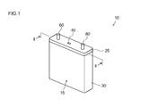
- FIG. 1 is a perspective view schematically showing a lithium ion secondary battery 10 according to the present embodiment.
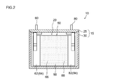
- FIG. 2 is a longitudinal sectional view taken along line II-II in FIG.
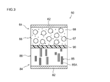
- FIG. 3 is a cross-sectional view of the wound electrode body 50 according to the present embodiment.
- the lithium ion secondary battery 10 according to this embodiment includes a battery case 15 made of metal (a resin or a laminate film is also suitable).
- the case (outer container) 15 includes a flat cuboid case main body 30 having an open upper end, and a lid body 25 that closes the opening 20.
- the lid body 25 seals the opening 20 of the case main body 30 by welding or the like.
- the lid body 25 On the upper surface of the case 15 (that is, the lid body 25), a positive electrode terminal 60 electrically connected to the positive electrode sheet (positive electrode) 64 of the wound electrode body 50 and a negative electrode terminal electrically connected to the negative electrode sheet 84 of the electrode body. 80 is provided.
- the lid 25 is provided with a safety valve 40 for discharging the gas generated inside the case 15 to the outside of the case 15 when the battery is abnormal, as in the case of the conventional lithium ion secondary battery. .
- the case 15 is manufactured by laminating and winding a positive electrode sheet 64 and a negative electrode sheet 84 together with a total of two separator sheets 90, and then crushing the obtained wound body from the side direction and abducting it. A flat wound electrode body 50 and the electrolyte solution are accommodated.
- the positive electrode mixture layer non-formed portion of the positive electrode sheet 64 (that is, the portion where the positive electrode current collector 62 is exposed without forming the positive electrode mixture layer 66) and the negative electrode sheet
- the negative electrode composite material layer non-formed portion 84 protrudes from both sides in the width direction of the separator sheet 90. And the negative electrode sheet 84 are overlapped with a slight shift in the width direction.
- the electrode composite material layer non-forming portions of the positive electrode sheet 64 and the negative electrode sheet 84 are respectively wound core portions (that is, the positive electrode composite material layer forming portion of the positive electrode sheet 64). And a portion where the negative electrode mixture layer forming portion of the negative electrode sheet 84 and the two separator sheets 90 are tightly wound) protrude outward.
- the positive electrode terminal 60 is joined to the protruding portion on the positive electrode side, and the positive electrode sheet 64 and the positive electrode terminal 60 of the wound electrode body 50 formed in the flat shape are electrically connected.
- the negative electrode terminal 80 is joined to the negative electrode side protruding portion, and the negative electrode sheet 84 and the negative electrode terminal 80 are electrically connected.
- the positive and negative electrode terminals 60 and 80 and the positive and negative electrode current collectors 62 and 82 can be joined by, for example, ultrasonic welding, resistance welding, or the like.
- FIG. 3 is a schematic cross-sectional view showing an enlarged central portion of the wound electrode body 50 in the winding axis direction.
- a positive electrode sheet 64 in which a positive electrode mixture layer 66 including a positive electrode active material (for example, lithium cobalt oxide) 67 and a conductive material 68 is formed on a positive electrode current collector 62, and a negative electrode current collector 82
- a separator sheet 90 is disposed between the negative electrode sheet 84 on which a negative electrode mixture layer 88 containing a graphite material 85 is formed.
- Both composite material layers 66 and 88 and separator sheet 90 are impregnated with an electrolytic solution (not shown) containing the lithium salt.
- At least 50% by mass of the graphite material 85 in the negative electrode mixture layer 88 is such that the (002) surface 85A of the graphite material is orthogonal to the surface (wide surface) of the negative electrode current collector 82 and It arrange
- FIG. Therefore, even if the graphite material 85 contained in the negative electrode mixture layer 88 contracts during the discharge of the lithium ion secondary battery 10 (see FIG. 1), the lithium salt or the like present in the graphite material 85 The electrolyte is less likely to flow out of the electrode body 50 from the width direction (winding axis direction) of the electrode body 50. That is, an increase in internal resistance of the electrode body due to a decrease in electrolyte (electrolytic solution) such as lithium salt can be suppressed.
- Example 1 Weigh natural graphite (negative electrode active material), SBR as a binder, and CMC as a thickener so that the mass ratio is 98: 1: 1, and disperse these materials in ion-exchanged water.
- a paste-like composition for forming a negative electrode mixture layer was prepared. The composition was applied onto a copper foil (negative electrode current collector) having a thickness of 10 ⁇ m at a coating amount of 4 mg / cm 2 per side, and a magnetic field was applied to the coated composition.
- the negative electrode sheet which concerns on Example 1 provided with a negative electrode compound material layer was produced by drying the composition after a magnetic field application.
- the magnetic field is applied to the composition by first applying a magnetic field in which magnetic lines of force are generated in the width direction of the current collector and then applying a magnetic field in which the direction of the lines of magnetic force is in a direction perpendicular to the current collector. This was done by continuously changing the direction of. The strength of the magnetic field at this time was 0.495T.
- the mass ratio of LiNi 1/3 Mn 1/3 Co 1/3 O 2 as the positive electrode active material, acetylene black (AB) as the conductive material, and PVDF as the binder is 90: 8: 2. Then, these materials were dispersed in NMP to prepare a paste-like composition for forming a positive electrode mixture layer.
- the composition was coated on a 15 ⁇ m thick aluminum foil at a coating amount of 6 mg / cm 2 per side and dried to prepare a positive electrode sheet according to Example 1 having a positive electrode mixture layer on the aluminum foil. Then, the prepared negative electrode sheet and positive electrode sheet according to Example 1 are wound together with two separator sheets (polypropylene / polyethylene composite porous membrane) and wound, and the obtained wound electrode body is crushed into a flat shape. This was accommodated in a cylindrical container together with the electrolyte solution to produce a lithium ion secondary battery according to Example 1.
- electrolytic solution a solution obtained by dissolving 1 mol / L LiPF 6 in a mixed solvent of ethylene carbonate (EC), dimethyl carbonate (DMC) and ethyl methyl carbonate (EMC) in a volume ratio of 1: 1: 1 was used. .
- EC ethylene carbonate
- DMC dimethyl carbonate
- EMC ethyl methyl carbonate
- ⁇ Comparative Example 1> A negative electrode sheet according to Comparative Example 1 was produced in the same manner as in Example 1 except that a magnetic field generating magnetic field lines in the direction perpendicular to the current collector was applied to the composition.
- a lithium ion secondary battery according to Comparative Example 1 was produced in the same manner as Example 1 except that the negative electrode sheet according to Comparative Example 1 was used.
- ⁇ Comparative Example 2> A negative electrode sheet according to Comparative Example 2 was produced in the same manner as in Example 1 except that no magnetic field was applied to the composition.
- a lithium ion secondary battery according to Comparative Example 2 was produced in the same manner as Example 1 except that the negative electrode sheet according to Comparative Example 2 was used.
- FIG. 11 to 13 are cross-sectional SEM (scanning electron microscope) photographs showing the states of the negative electrode sheets of Example 1, Comparative Example 1 and Comparative Example 2.
- FIG. 13 in the negative electrode sheet in which no magnetic field is applied to the negative electrode sheet, the natural graphite (negative electrode active material) is not arranged in the direction orthogonal to the negative electrode current collector in the negative electrode mixture layer, but randomly. It was confirmed that it was placed.
- FIG. 12 in the negative electrode sheet in which a magnetic field is applied in the direction perpendicular to the negative current collector, a part of natural graphite (negative electrode active material) in the negative electrode mixture layer is perpendicular to the surface of the negative electrode current collector.
- the current collector was randomly arranged in the longitudinal direction of the current collector.
- FIG. 11 when a magnetic field is continuously applied to the negative electrode sheet from the current collector width direction to the current collector orthogonal direction, most of the natural graphite in the negative electrode mixture layer is negative electrode current collector. It was confirmed that they were arranged (arranged) so as to be orthogonal to the surface of the body and parallel to the longitudinal direction of the negative electrode current collector.
- the lithium ion secondary battery including the negative electrode according to the present invention has low internal resistance and excellent battery performance, it can be suitably used as a power source for a motor (electric motor) mounted on a vehicle such as an automobile. Therefore, as schematically shown in FIG. 15, the present invention provides a vehicle (typically, a lithium-ion secondary battery 10 (typically, an assembled battery formed by connecting a plurality of the batteries 10 in series) as a power source (typically Provides a motor vehicle, particularly a motor vehicle equipped with an electric motor such as a hybrid vehicle, an electric vehicle, and a fuel vehicle.
- a vehicle typically, a lithium-ion secondary battery 10 (typically, an assembled battery formed by connecting a plurality of the batteries 10 in series)
- a power source typically Provides a motor vehicle, particularly a motor vehicle equipped with an electric motor such as a hybrid vehicle, an electric vehicle, and a fuel vehicle.
Landscapes
- Chemical & Material Sciences (AREA)
- Engineering & Computer Science (AREA)
- Chemical Kinetics & Catalysis (AREA)
- Electrochemistry (AREA)
- General Chemical & Material Sciences (AREA)
- Manufacturing & Machinery (AREA)
- Materials Engineering (AREA)
- Inorganic Chemistry (AREA)
- Battery Electrode And Active Subsutance (AREA)
- Secondary Cells (AREA)
Abstract
Priority Applications (5)
| Application Number | Priority Date | Filing Date | Title |
|---|---|---|---|
| KR1020137023886A KR101543937B1 (ko) | 2011-02-18 | 2011-02-18 | 리튬 이온 2차 전지와 그 제조 방법 |
| JP2012557769A JP5601550B2 (ja) | 2011-02-18 | 2011-02-18 | リチウムイオン二次電池とその製造方法 |
| US13/985,601 US9166247B2 (en) | 2011-02-18 | 2011-02-18 | Lithium-ion secondary cell and method for manufacturing same |
| PCT/JP2011/053570 WO2012111161A1 (fr) | 2011-02-18 | 2011-02-18 | Pile secondaire au lithium-ion et son procédé de fabrication |
| CN201180067749.2A CN103380519B (zh) | 2011-02-18 | 2011-02-18 | 锂离子二次电池及其制造方法 |
Applications Claiming Priority (1)
| Application Number | Priority Date | Filing Date | Title |
|---|---|---|---|
| PCT/JP2011/053570 WO2012111161A1 (fr) | 2011-02-18 | 2011-02-18 | Pile secondaire au lithium-ion et son procédé de fabrication |
Publications (1)
| Publication Number | Publication Date |
|---|---|
| WO2012111161A1 true WO2012111161A1 (fr) | 2012-08-23 |
Family
ID=46672121
Family Applications (1)
| Application Number | Title | Priority Date | Filing Date |
|---|---|---|---|
| PCT/JP2011/053570 Ceased WO2012111161A1 (fr) | 2011-02-18 | 2011-02-18 | Pile secondaire au lithium-ion et son procédé de fabrication |
Country Status (5)
| Country | Link |
|---|---|
| US (1) | US9166247B2 (fr) |
| JP (1) | JP5601550B2 (fr) |
| KR (1) | KR101543937B1 (fr) |
| CN (1) | CN103380519B (fr) |
| WO (1) | WO2012111161A1 (fr) |
Cited By (10)
| Publication number | Priority date | Publication date | Assignee | Title |
|---|---|---|---|---|
| JP2014137879A (ja) * | 2013-01-16 | 2014-07-28 | Toyota Motor Corp | 二次電池 |
| JP2019534155A (ja) * | 2016-09-06 | 2019-11-28 | バトリオン・アクチェンゲゼルシャフトBattrion AG | 物品への磁界付与方法及び装置 |
| JP2022515678A (ja) * | 2019-01-07 | 2022-02-21 | ユーシーエル ビジネス リミテッド | 電気化学セルの性能を増強する方法 |
| JP2024540560A (ja) * | 2022-10-13 | 2024-10-31 | エルジー エナジー ソリューション リミテッド | 負極用磁性整列装置およびそれを用いた負極の製造方法 |
| JP2024540499A (ja) * | 2022-09-15 | 2024-10-31 | エルジー エナジー ソリューション リミテッド | 負極用磁性整列装置およびそれを用いた負極の製造方法 |
| JP2025502009A (ja) * | 2022-09-15 | 2025-01-24 | エルジー エナジー ソリューション リミテッド | 負極用磁性整列装置およびそれを用いた負極の製造方法 |
| JP2025501991A (ja) * | 2022-09-15 | 2025-01-24 | エルジー エナジー ソリューション リミテッド | 負極用磁性整列装置およびそれを用いた負極の製造方法 |
| JP2025502010A (ja) * | 2022-09-15 | 2025-01-24 | エルジー エナジー ソリューション リミテッド | 負極用磁性整列装置およびそれを用いた負極の製造方法 |
| JP2025504761A (ja) * | 2022-09-15 | 2025-02-19 | エルジー エナジー ソリューション リミテッド | 負極用磁性整列装置およびそれを用いた負極の製造方法 |
| JP7838092B2 (ja) | 2022-09-15 | 2026-03-31 | エルジー エナジー ソリューション リミテッド | 負極用磁性整列装置およびそれを用いた負極の製造方法 |
Families Citing this family (15)
| Publication number | Priority date | Publication date | Assignee | Title |
|---|---|---|---|---|
| CN104584271B (zh) * | 2012-09-12 | 2018-04-17 | 株式会社杰士汤浅国际 | 蓄电元件以及蓄电元件的制造方法 |
| CN103972475B (zh) * | 2014-04-16 | 2016-05-11 | 山东精工电子科技有限公司 | 提高磷酸铁锂正极材料压实密度的装置 |
| CN105322178B (zh) * | 2015-10-16 | 2019-01-01 | 广东烛光新能源科技有限公司 | 一种电化学电池电极、含有该电极的电化学电池及其制备方法 |
| WO2018047054A1 (fr) * | 2016-09-06 | 2018-03-15 | Battrion Ag | Procédé et dispositif pour appliquer des champs magnétiques sur un objet |
| KR102483995B1 (ko) * | 2016-12-07 | 2022-12-30 | 삼성에스디아이 주식회사 | 이차 전지용 음극 및 그의 제조 방법 |
| DE102017111463B4 (de) * | 2017-05-24 | 2022-11-17 | Leibniz-Institut Für Festkörper- Und Werkstoffforschung Dresden E.V. | Aufgerollte energiespeicherbauelemente und verfahren zu ihrer herstellung |
| JP2021515975A (ja) * | 2018-02-28 | 2021-06-24 | バトリオン・アクチェンゲゼルシャフトBattrion AG | コーティングの製造のための方法 |
| KR102536366B1 (ko) | 2019-04-24 | 2023-05-23 | 삼성에스디아이 주식회사 | 리튬 이차 전지용 음극 및 이를 포함하는 리튬 이차 전지 |
| KR102570570B1 (ko) | 2019-04-24 | 2023-08-23 | 삼성에스디아이 주식회사 | 리튬 이차 전지용 음극 및 이를 포함하는 리튬 이차 전지 |
| US12015145B2 (en) * | 2020-01-02 | 2024-06-18 | Ningde Amperex Technology Limited | Anode, and electrochemical device comprising the same |
| CN112259785B (zh) * | 2020-10-27 | 2021-08-24 | 江西理工大学 | 一种单叠片对数软包锂离子电池及其制备方法 |
| CN113410426A (zh) * | 2021-07-30 | 2021-09-17 | 湖南立方新能源科技有限责任公司 | 一种锂离子电池 |
| DE102021133008A1 (de) * | 2021-12-14 | 2023-06-15 | Battrion Ag | Verfahren zur Herstellung einer Elektrode mit heterogener Mehrfachbeschichtung |
| CN114335416B (zh) * | 2021-12-17 | 2024-03-26 | 湖南立方新能源科技有限责任公司 | 一种复合负极片及其制备方法、锂离子电池和用电装置 |
| KR102617498B1 (ko) * | 2022-10-13 | 2023-12-27 | 주식회사 엘지에너지솔루션 | 리튬 이차전지용 음극 및 이를 위한 음극용 자성 정렬 장치 |
Citations (9)
| Publication number | Priority date | Publication date | Assignee | Title |
|---|---|---|---|---|
| JPH08111219A (ja) * | 1994-10-11 | 1996-04-30 | Shin Kobe Electric Mach Co Ltd | リチウムイオン二次電池 |
| JPH09245770A (ja) * | 1996-03-06 | 1997-09-19 | Sanyo Electric Co Ltd | 非水電解液電池 |
| JPH09306477A (ja) * | 1996-05-09 | 1997-11-28 | Matsushita Electric Ind Co Ltd | 非水電解液二次電池 |
| JPH10321219A (ja) * | 1997-05-20 | 1998-12-04 | Mitsubishi Cable Ind Ltd | 電池用負極の製造方法 |
| JP2001196051A (ja) * | 2000-01-11 | 2001-07-19 | At Battery:Kk | 非水系二次電池及び非水系二次電池の製造方法 |
| US20040072076A1 (en) * | 2001-12-21 | 2004-04-15 | Keiko Matsubara | Graphite-containing composition, negative electrode for a lithium secondary battery, and lithium secondary battery |
| JP2004220926A (ja) * | 2003-01-15 | 2004-08-05 | Matsushita Electric Ind Co Ltd | 非水電解質二次電池用負極 |
| JP2005056645A (ja) * | 2003-08-01 | 2005-03-03 | Matsushita Electric Ind Co Ltd | 非水電解質二次電池およびその製造法 |
| JP2006083030A (ja) * | 2004-09-17 | 2006-03-30 | Sony Corp | 黒鉛粉末および非水電解質二次電池 |
Family Cites Families (4)
| Publication number | Priority date | Publication date | Assignee | Title |
|---|---|---|---|---|
| JP2003197182A (ja) * | 2001-12-21 | 2003-07-11 | Samsung Sdi Co Ltd | 黒鉛含有組成物並びにリチウム二次電池用の負極及びリチウム二次電池 |
| JP4150516B2 (ja) | 2001-12-21 | 2008-09-17 | 三星エスディアイ株式会社 | リチウム二次電池の負極用の黒鉛含有組成物の製造方法並びにリチウム二次電池用の負極の製造方法及びリチウム二次電池の製造方法 |
| JP2006252945A (ja) | 2005-03-10 | 2006-09-21 | Sony Corp | 非水電解質二次電池用の電極及びその製造方法、並びに非水電解質二次電池 |
| JP4510912B2 (ja) * | 2007-09-06 | 2010-07-28 | パナソニック株式会社 | 非水電解液電池 |
-
2011
- 2011-02-18 WO PCT/JP2011/053570 patent/WO2012111161A1/fr not_active Ceased
- 2011-02-18 KR KR1020137023886A patent/KR101543937B1/ko active Active
- 2011-02-18 JP JP2012557769A patent/JP5601550B2/ja active Active
- 2011-02-18 CN CN201180067749.2A patent/CN103380519B/zh active Active
- 2011-02-18 US US13/985,601 patent/US9166247B2/en active Active
Patent Citations (9)
| Publication number | Priority date | Publication date | Assignee | Title |
|---|---|---|---|---|
| JPH08111219A (ja) * | 1994-10-11 | 1996-04-30 | Shin Kobe Electric Mach Co Ltd | リチウムイオン二次電池 |
| JPH09245770A (ja) * | 1996-03-06 | 1997-09-19 | Sanyo Electric Co Ltd | 非水電解液電池 |
| JPH09306477A (ja) * | 1996-05-09 | 1997-11-28 | Matsushita Electric Ind Co Ltd | 非水電解液二次電池 |
| JPH10321219A (ja) * | 1997-05-20 | 1998-12-04 | Mitsubishi Cable Ind Ltd | 電池用負極の製造方法 |
| JP2001196051A (ja) * | 2000-01-11 | 2001-07-19 | At Battery:Kk | 非水系二次電池及び非水系二次電池の製造方法 |
| US20040072076A1 (en) * | 2001-12-21 | 2004-04-15 | Keiko Matsubara | Graphite-containing composition, negative electrode for a lithium secondary battery, and lithium secondary battery |
| JP2004220926A (ja) * | 2003-01-15 | 2004-08-05 | Matsushita Electric Ind Co Ltd | 非水電解質二次電池用負極 |
| JP2005056645A (ja) * | 2003-08-01 | 2005-03-03 | Matsushita Electric Ind Co Ltd | 非水電解質二次電池およびその製造法 |
| JP2006083030A (ja) * | 2004-09-17 | 2006-03-30 | Sony Corp | 黒鉛粉末および非水電解質二次電池 |
Cited By (21)
| Publication number | Priority date | Publication date | Assignee | Title |
|---|---|---|---|---|
| JP2014137879A (ja) * | 2013-01-16 | 2014-07-28 | Toyota Motor Corp | 二次電池 |
| JP2019534155A (ja) * | 2016-09-06 | 2019-11-28 | バトリオン・アクチェンゲゼルシャフトBattrion AG | 物品への磁界付与方法及び装置 |
| JP7237363B2 (ja) | 2016-09-06 | 2023-03-13 | バトリオン・アクチェンゲゼルシャフト | 物品への磁界付与方法及び装置 |
| JP2022515678A (ja) * | 2019-01-07 | 2022-02-21 | ユーシーエル ビジネス リミテッド | 電気化学セルの性能を増強する方法 |
| JP7399170B2 (ja) | 2019-01-07 | 2023-12-15 | ユーシーエル ビジネス リミテッド | 電気化学セルの性能を増強する方法 |
| JP2024037796A (ja) * | 2019-01-07 | 2024-03-19 | ユーシーエル ビジネス リミテッド | 電気化学セルの性能を増強する方法 |
| JP7576146B2 (ja) | 2019-01-07 | 2024-10-30 | ユーシーエル ビジネス リミテッド | 電気化学セルの性能を増強する方法 |
| JP7739569B2 (ja) | 2019-01-07 | 2025-09-16 | ユーシーエル ビジネス リミテッド | 電気化学セルの性能を増強する方法 |
| JP2025020174A (ja) * | 2019-01-07 | 2025-02-12 | ユーシーエル ビジネス リミテッド | 電気化学セルの性能を増強する方法 |
| JP2025501991A (ja) * | 2022-09-15 | 2025-01-24 | エルジー エナジー ソリューション リミテッド | 負極用磁性整列装置およびそれを用いた負極の製造方法 |
| JP2025502009A (ja) * | 2022-09-15 | 2025-01-24 | エルジー エナジー ソリューション リミテッド | 負極用磁性整列装置およびそれを用いた負極の製造方法 |
| JP2025502010A (ja) * | 2022-09-15 | 2025-01-24 | エルジー エナジー ソリューション リミテッド | 負極用磁性整列装置およびそれを用いた負極の製造方法 |
| JP2024540499A (ja) * | 2022-09-15 | 2024-10-31 | エルジー エナジー ソリューション リミテッド | 負極用磁性整列装置およびそれを用いた負極の製造方法 |
| JP2025504761A (ja) * | 2022-09-15 | 2025-02-19 | エルジー エナジー ソリューション リミテッド | 負極用磁性整列装置およびそれを用いた負極の製造方法 |
| JP7701127B2 (ja) | 2022-09-15 | 2025-07-01 | エルジー エナジー ソリューション リミテッド | 負極用磁性整列装置およびそれを用いた負極の製造方法 |
| JP7701126B2 (ja) | 2022-09-15 | 2025-07-01 | エルジー エナジー ソリューション リミテッド | 負極用磁性整列装置およびそれを用いた負極の製造方法 |
| JP7726602B2 (ja) | 2022-09-15 | 2025-08-20 | エルジー エナジー ソリューション リミテッド | 負極用磁性整列装置およびそれを用いた負極の製造方法 |
| JP7801004B2 (ja) | 2022-09-15 | 2026-01-16 | エルジー エナジー ソリューション リミテッド | 負極用磁性整列装置およびそれを用いた負極の製造方法 |
| JP7838092B2 (ja) | 2022-09-15 | 2026-03-31 | エルジー エナジー ソリューション リミテッド | 負極用磁性整列装置およびそれを用いた負極の製造方法 |
| JP7726603B2 (ja) | 2022-10-13 | 2025-08-20 | エルジー エナジー ソリューション リミテッド | 負極用磁性整列装置およびそれを用いた負極の製造方法 |
| JP2024540560A (ja) * | 2022-10-13 | 2024-10-31 | エルジー エナジー ソリューション リミテッド | 負極用磁性整列装置およびそれを用いた負極の製造方法 |
Also Published As
| Publication number | Publication date |
|---|---|
| KR101543937B1 (ko) | 2015-08-11 |
| CN103380519A (zh) | 2013-10-30 |
| US9166247B2 (en) | 2015-10-20 |
| KR20130118989A (ko) | 2013-10-30 |
| JP5601550B2 (ja) | 2014-10-08 |
| JPWO2012111161A1 (ja) | 2014-07-03 |
| CN103380519B (zh) | 2016-04-13 |
| US20140072848A1 (en) | 2014-03-13 |
Similar Documents
| Publication | Publication Date | Title |
|---|---|---|
| JP5601550B2 (ja) | リチウムイオン二次電池とその製造方法 | |
| US10522816B2 (en) | Lithium secondary battery | |
| JP5229598B2 (ja) | リチウム二次電池及びその製造方法 | |
| JP5614600B2 (ja) | リチウムイオン二次電池及びその製造方法 | |
| US9263729B2 (en) | Lithium secondary battery | |
| JP6380808B2 (ja) | 二次電池用電極の製造方法 | |
| JP2013069432A (ja) | リチウムイオン二次電池とその製造方法 | |
| CN103107338A (zh) | 制造锂二次电池的方法 | |
| US9917296B2 (en) | Nonaqueous electrolyte secondary battery | |
| JP2013069579A (ja) | リチウムイオン二次電池とその製造方法 | |
| JP5812336B2 (ja) | 二次電池 | |
| JP2013131342A (ja) | 二次電池及びその製造方法ならびに該電池に用いられる負極シートの製造方法 | |
| WO2011108119A1 (fr) | Batterie secondaire au lithium et séparateur à utiliser dans ladite batterie | |
| JP2013069431A (ja) | リチウムイオン二次電池とその製造方法 | |
| JP5605614B2 (ja) | リチウム二次電池の製造方法 |
Legal Events
| Date | Code | Title | Description |
|---|---|---|---|
| 121 | Ep: the epo has been informed by wipo that ep was designated in this application |
Ref document number: 11858746 Country of ref document: EP Kind code of ref document: A1 |
|
| ENP | Entry into the national phase |
Ref document number: 2012557769 Country of ref document: JP Kind code of ref document: A |
|
| NENP | Non-entry into the national phase |
Ref country code: DE |
|
| ENP | Entry into the national phase |
Ref document number: 20137023886 Country of ref document: KR Kind code of ref document: A |
|
| WWE | Wipo information: entry into national phase |
Ref document number: 13985601 Country of ref document: US |
|
| 122 | Ep: pct application non-entry in european phase |
Ref document number: 11858746 Country of ref document: EP Kind code of ref document: A1 |