WO2012111208A1 - Dispositif de codage d'image vidéo - Google Patents
Dispositif de codage d'image vidéo Download PDFInfo
- Publication number
- WO2012111208A1 WO2012111208A1 PCT/JP2011/076878 JP2011076878W WO2012111208A1 WO 2012111208 A1 WO2012111208 A1 WO 2012111208A1 JP 2011076878 W JP2011076878 W JP 2011076878W WO 2012111208 A1 WO2012111208 A1 WO 2012111208A1
- Authority
- WO
- WIPO (PCT)
- Prior art keywords
- prediction
- image
- pixel
- intra
- error
- Prior art date
- Legal status (The legal status is an assumption and is not a legal conclusion. Google has not performed a legal analysis and makes no representation as to the accuracy of the status listed.)
- Ceased
Links
Images


Classifications
-
- H—ELECTRICITY
- H04—ELECTRIC COMMUNICATION TECHNIQUE
- H04N—PICTORIAL COMMUNICATION, e.g. TELEVISION
- H04N19/00—Methods or arrangements for coding, decoding, compressing or decompressing digital video signals
- H04N19/50—Methods or arrangements for coding, decoding, compressing or decompressing digital video signals using predictive coding
-
- H—ELECTRICITY
- H04—ELECTRIC COMMUNICATION TECHNIQUE
- H04N—PICTORIAL COMMUNICATION, e.g. TELEVISION
- H04N19/00—Methods or arrangements for coding, decoding, compressing or decompressing digital video signals
- H04N19/10—Methods or arrangements for coding, decoding, compressing or decompressing digital video signals using adaptive coding
- H04N19/169—Methods or arrangements for coding, decoding, compressing or decompressing digital video signals using adaptive coding characterised by the coding unit, i.e. the structural portion or semantic portion of the video signal being the object or the subject of the adaptive coding
- H04N19/17—Methods or arrangements for coding, decoding, compressing or decompressing digital video signals using adaptive coding characterised by the coding unit, i.e. the structural portion or semantic portion of the video signal being the object or the subject of the adaptive coding the unit being an image region, e.g. an object
- H04N19/176—Methods or arrangements for coding, decoding, compressing or decompressing digital video signals using adaptive coding characterised by the coding unit, i.e. the structural portion or semantic portion of the video signal being the object or the subject of the adaptive coding the unit being an image region, e.g. an object the region being a block, e.g. a macroblock
-
- H—ELECTRICITY
- H04—ELECTRIC COMMUNICATION TECHNIQUE
- H04N—PICTORIAL COMMUNICATION, e.g. TELEVISION
- H04N19/00—Methods or arrangements for coding, decoding, compressing or decompressing digital video signals
- H04N19/10—Methods or arrangements for coding, decoding, compressing or decompressing digital video signals using adaptive coding
- H04N19/102—Methods or arrangements for coding, decoding, compressing or decompressing digital video signals using adaptive coding characterised by the element, parameter or selection affected or controlled by the adaptive coding
- H04N19/103—Selection of coding mode or of prediction mode
- H04N19/11—Selection of coding mode or of prediction mode among a plurality of spatial predictive coding modes
-
- H—ELECTRICITY
- H04—ELECTRIC COMMUNICATION TECHNIQUE
- H04N—PICTORIAL COMMUNICATION, e.g. TELEVISION
- H04N19/00—Methods or arrangements for coding, decoding, compressing or decompressing digital video signals
- H04N19/10—Methods or arrangements for coding, decoding, compressing or decompressing digital video signals using adaptive coding
- H04N19/134—Methods or arrangements for coding, decoding, compressing or decompressing digital video signals using adaptive coding characterised by the element, parameter or criterion affecting or controlling the adaptive coding
- H04N19/136—Incoming video signal characteristics or properties
-
- H—ELECTRICITY
- H04—ELECTRIC COMMUNICATION TECHNIQUE
- H04N—PICTORIAL COMMUNICATION, e.g. TELEVISION
- H04N19/00—Methods or arrangements for coding, decoding, compressing or decompressing digital video signals
- H04N19/60—Methods or arrangements for coding, decoding, compressing or decompressing digital video signals using transform coding
- H04N19/61—Methods or arrangements for coding, decoding, compressing or decompressing digital video signals using transform coding in combination with predictive coding
Definitions
- the present invention relates to a moving picture coding apparatus, and more particularly to a moving picture coding apparatus that performs selection between intra prediction and inter prediction on the encoding side.
- H.264 is known as the latest standard for highly efficient moving image compression technology.
- H.264 is a video developed by JVT jointly established in December 2001 by the ITU-T Video Coding Expert Group (VCEG) and ISO / IEC Video Coding Expert Group (MPEG). It is an international standard for encoding. ITU-T approved as a recommendation in May 2003. MPEG-4 Part 10 in 2003 at ISO / IEC JTC Standardized as Advanced Video Coding (AVC).
- AVC Advanced Video Coding
- FREx Fidelity Range Extension
- H.264 The main features of H.264 are as follows. -Achieves the same level of image quality with about twice the coding efficiency compared to conventional MPEG-2 and MPEG-4-Compression algorithm: Adopt inter-picture prediction, quantization, entropy code-Low bit for mobile phones, etc. In this way, video coding technology has been discussed in various ways, and standardization work for H.265 is currently underway as the next standard.
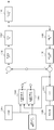
- FIG. 1 is a general configuration diagram of an encoder 1 that performs encoding using H.264.
- in-screen prediction (104) for generating a predicted image within one screen and inter-screen prediction (105) for generating a predicted image from a plurality of screens are defined.
- Select either intra-screen prediction or inter-screen prediction according to a predetermined criterion take the difference between the selected predicted image and the input image (101), and perform the subsequent orthogonal transformation (102), quantum (103) is performed, and the quantized data is encoded (110).
- the reconstructed image (106) used as the reference image in the inter-screen prediction process (105) is obtained by performing orthogonal transform and quantization on the data after quantization (103) (or after entropy coding (110)).
- dequantization (109) and inverse orthogonal transform (108), which are the reverse of the above the data added to the predicted image is subjected to deblocking filtering (107) that reduces block noise. .
- the deblocking filter may not be used. H.264 realizes high encoding efficiency for encoding and transmitting only differential images.
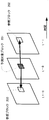
- FIG. 2 is a diagram for explaining inter-screen prediction.
- This is a process of calculating a motion vector of a prediction target block from a reference block (200/202) of a picture and generating a predicted image.
- FIG. 3 is a diagram for explaining in-screen prediction.
- In-screen prediction is a technique for generating a predicted image using correlation between adjacent pixels.
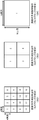
- the screen is divided into processing blocks called slices (300) of m ⁇ n pixels, and the slice is further divided into macro blocks (301) of 16 ⁇ 16 pixels.
- the macro block 301 is used as a basic processing unit, and a predicted image is generated for each 4 ⁇ 4, 8 ⁇ 8, and 16 ⁇ 16 pixel block.
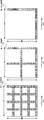
- FIG. 4 shows the processing order of pixel blocks in the case of 4 ⁇ 4, 8 ⁇ 8, and 16 ⁇ 16. That is, processing is performed in ascending order of the number shown in each pixel block.
- FIG. 5 shows reference pixels used for predictive image generation for intra-screen prediction in units of 4 ⁇ 4 pixels.
- a to M are reference pixels 400 used for prediction with respect to 16 prediction target pixels 401 a to p included in the prediction target block in FIG.
- H.264 / AVC 4 ⁇ 4 pixel block units (hereinafter: 4 ⁇ 4 blocks), 8 ⁇ 8 pixel block units (hereinafter: 8 ⁇ 8 blocks), 16 ⁇ 16 pixel block units (hereinafter: 16 ⁇ ) It is possible to generate a predicted image in 16 blocks.
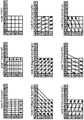
- the processing method that stipulates the process of generating the prediction target block from the reference pixels is called a mode, and usable modes are 9 modes each for 4x4 block and 8x8 block, and 4 modes for 16x16 block. It is possible.
- FIG. 6 shows nine modes that can be used in a 4 ⁇ 4 block as an example.
- H.264 which is the latest video coding standard, various methods are used to realize a highly efficient compression technique.
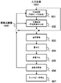
- FIG. 7 is a flowchart of the encoding process performed by the encoder 1.
- the intra prediction process is used as the prediction process
- the encoding process when an input image is input, a prediction image of a prediction target block is generated from the reconstructed image for all prediction modes, a difference from the input image is calculated, and a sum of absolute differences (hereinafter, SAD: The mode with the smallest sum of absolute differences is determined as the optimum prediction mode for intra prediction (601).
- SAD is defined by the following formula, for example. Note that ⁇ i means that all pixels in the prediction target block are targeted.
- SAD is generally used as an evaluation scale, evaluation values other than the above formula may be used.
- the method for determining the prediction mode is not specified in the standard, but depends on the design.
- a prediction image is generated in the prediction mode determined from the reconstructed image (608) (602), and a difference image from the input image is obtained.
- a reconstructed image (608) is obtained through orthogonal transformation (603), quantization (604), inverse quantization (605), and inverse orthogonal transformation (606).
- entropy coding is performed by a technique such as variable length coding (CAVLC) / arithmetic coding (CABAC) (607), and a stream is generated.
- CAVLC variable length coding
- CABAC arithmetic coding
- the image encoding device of Patent Document 1 has a problem that the amount of processing such as Hadamard transform for prediction errors is high.
- the present invention provides a moving image encoding apparatus capable of preventing a significant deterioration in image quality even in applications requiring high-speed processing by performing mode selection that reduces error propagation with processing that can be pipelined with a low processing amount. The purpose is to do.
- the moving image encoding device is a moving image encoding device that selects one of a plurality of intra-screen prediction modes and encodes a pixel block.
- Pseudo-prediction image generation unit that generates pseudo-prediction from the image, and prediction errors of the plurality of prediction images generated by the pseudo-prediction image generation unit are calculated by weighting pixels that can be reference pixels in intra-screen prediction of other pixel blocks
- a prediction mode determination unit that determines a prediction mode based on the calculated plurality of prediction errors.
- the pseudo prediction image generation unit generates the prediction image using a pixel acquired without receiving a quantization error from an input image as a reference pixel, and determines the prediction mode.
- the unit calculates the prediction error by giving a greater weight to the pixel that can be the reference pixel than a pixel other than the pixel that can be the reference pixel, and among the plurality of calculated prediction errors, the minimum prediction error
- the prediction mode corresponding to is determined to be the optimal prediction mode in the intra-screen prediction.
- the pixel block is obtained by dividing an input image in a predetermined order, and pixels obtained without receiving the quantization error are pixels directly obtained from the input image or pseudo prediction.
- the pixel that is directly obtained from the predicted image generated by the image generation unit and that can be the reference pixel is a pixel that can be referred to in intra-screen prediction in the subsequent pixel block in the order and is a pixel block to be encoded. It is a pixel on the lowermost side or the rightmost side, and the prediction mode determination unit changes the weight according to a size of a pixel block to be encoded or a quantization parameter.
- a moving image encoding method is a moving image encoding method for encoding a pixel block by selecting one of a plurality of intra-screen prediction modes, and a predicted image according to the plurality of intra-screen prediction modes, A step of pseudo-generating from an input image, and calculating a prediction error of the plurality of prediction images generated by the pseudo-prediction image generation unit by calculating a weight of a pixel that can be a reference pixel in an intra-screen prediction of another pixel block, A step of determining a prediction mode based on the plurality of calculated prediction errors, a step of generating a prediction image from a reconstructed image according to the determined prediction mode, and a generation from the reconstructed image from the input image Obtaining a difference image by subtracting the predicted image obtained, orthogonally transforming the difference image to obtain a coefficient, quantizing the coefficient, and reciprocating the quantized coefficient However, inverse orthogonal transform, the basis of the image obtained by adding the predicted image generated from the reconstructed image,
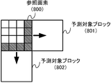
- FIG. 8 is a diagram for explaining propagation of a prediction error in intra prediction.
- a prediction image is generated from the reference pixel 800 adjacent thereto. If the error (prediction error) of the reference pixel 800 is large, the prediction error of the prediction target block (801/802) predicted therefrom is also large. That is, the prediction error of the reference pixel propagates to the adjacent block. Further, when the next adjacent block refers to the value, the prediction error distribution is further expanded.
- H.264 intra prediction has the property that even if the best prediction mode is selected continuously, the prediction error gradually increases as the coding progresses. Further, when a pseudo prediction image is used, an incorrect prediction mode selection accelerates an increase in prediction error, resulting in a decrease in image quality.
- FIG. 9 is a diagram illustrating an example of pixels to be weighted, and the filled portions (the pixels on the lowermost side and the rightmost side in the block) are the pixels to be weighted.
- SAD ′ The calculation formula when the weighting of this example is applied to SAD is shown below as SAD ′.
- ⁇ is a weighting factor (usually 1 or more), and is a value that can be arbitrarily set for each prediction mode.
- Step SAD a stepwise difference sum of absolute values
- FIG. 10 is a conceptual diagram of SAD and SSAD.
- the vertical axis represents the values of SAD and SSAD, and SAD increases proportionally as the prediction error increases.
- SSAD is an evaluation value whose evaluation value changes stepwise according to the prediction error.
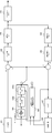
- FIG. 11 is a block diagram of the encoder according to the first embodiment of the present invention.
- the encoder in FIG. 11 performs encoding according to H.264 as in FIG. 1, but the configuration of the in-screen prediction processing unit 1040 is different.
- the intra-screen prediction processing unit 1040 of this example includes a pseudo prediction image generation unit 1041 and a prediction mode determination unit 1042.
- the pseudo predicted image generation unit 1041 generates a pseudo predicted image for all the intra-screen prediction modes defined in H.264. That is, the prediction is based on the input image 101 instead of the reconstructed image.
- the calculation method of the prediction process in each mode is a method that complies with the H.264 standard.
- Prediction based on the input image 101 is a method of always acquiring reference pixels from the input image 101 (a method of simply substituting the reconstructed image with the input image), or acquiring from the input image 101 only for the first time, and thereafter, determining the prediction mode
- a pseudo prediction image in the prediction mode selected by the unit 1042 is held and acquired from the pseudo prediction image.
- the prediction mode determination unit 1042 is a characteristic part of this example, and determines the prediction mode based on the evaluation value SAD ′ obtained by weighting the reference pixels. That is, the prediction mode indicating the minimum SAD ′ is selected.
- the calculation of SAD ′ is as shown in Equation 2, but it is more effective not only to set the weight ⁇ as a fixed value but also to change it according to the quantization parameter and the size of the prediction block.
- the larger the quantization parameter or the smaller the predicted block size the higher the effect obtained when the weight ⁇ is set larger.
- the prediction mode determination unit 1042 calculates or acquires the main prediction error for the selected prediction mode from the inverse orthogonal transform unit 108 and the pseudo prediction error of the prediction mode obtained from the similar prediction image generation unit 1041.
- the ratio may be calculated, the average value may be held for each prediction mode, and the weight ⁇ may be adaptively updated.
- the predicted image generation unit 1043 generates a predicted image of the determined prediction mode using the reconstructed image (1008).
- the subsequent processing is the same as general encoder processing. That is, the difference between the input image and the predicted image is calculated, and orthogonal transformation is performed by the orthogonal transformation unit 102 to obtain a coefficient.
- the quantization unit 103 quantizes the coefficient.
- the quantized coefficient is encoded, inversely quantized by the inverse quantization unit 109, inversely orthogonal transformed by the inverse orthogonal transform unit 108, and added to the prediction image used when taking the difference from the input image, An image (decoded image) close to the input image is reconstructed (updated reconstructed image) by appropriately connecting the images (pixel blocks) thus obtained by applying a deblocking filter.
- the stream generated by the encoder of this example can be decoded by a general H.264 decoder.
- mode determination can proceed without waiting for a reconstructed image to be obtained, and processing can be parallelized or pipelined.
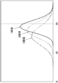
- FIG. 12 is a diagram conceptually showing a distribution of pseudo prediction errors normalized by the main prediction error.
- the horizontal axis is the prediction error (SAD value)
- the vertical axis is the probability of occurrence
- the distribution of the pseudo prediction error of the same pixel block when the main prediction error in an arbitrary pixel block is normalized to 50 is The number of blocks before the intra-screen prediction (pseudo-prediction) has continued (1 to 3 times).
- prediction is performed from a reconstructed image in which information is lost due to quantization or the like, while in pseudo prediction, prediction from an input image and local correlation can be used with high accuracy. Accumulation of prediction errors is slow. Therefore, the expected value of the prediction error decreases as the number of consecutive times increases, but the width of the distribution increases.
- the probability of selecting a mode different from the main prediction can be reduced. If the different selection probability becomes smaller, the width of the distribution after the second time also becomes narrower.
- the intra prediction error tends to be farther from the reference pixel, and the lower right pixel in the prediction target block tends to be larger, and this tendency is stronger in the main prediction in which the reference pixel is deteriorated from the input image.
- a weight that increases toward the lower right in the block for obtaining the pseudo prediction error may be given to approximate the characteristic of the prediction error.
- the sequence obtained by always determining the prediction mode based on the prediction error (hereinafter referred to as the best prediction mode selection sequence) is selected at least every time the prediction target block has the smallest prediction error. It seems that the selection is close to.
- a policy of preventing mode selection by pseudo prediction from deviating from the best prediction mode selection sequence as much as possible can be one solution.
- the weight ⁇ of this example has the effect of bringing the pseudo prediction error closer to the main prediction error, and the effect of reducing the prediction error accumulation by making it difficult to select a prediction mode in which the error easily propagates to the next block.
- Two actions can be considered, but it is considered that the latter contributes to the image quality improvement of this example. Therefore, in some cases, there is a possibility that the best mode selection sequence can be obtained more than the main prediction without using the weight ⁇ . This effect is brought about by giving a large weight to a pixel that can be a reference pixel.
- evaluation of activity values (reflecting the in-screen prediction cost) described in Patent Document 4 is performed. It can also be used when calculating values.
- the latter effect can be exhibited by the mode selection of the main prediction or the intra-screen / inter-screen prediction selection (especially when judging for each macroblock).
- SAD ' is used for prediction error calculation for both intra-screen prediction and inter-screen prediction, and after correction at a predetermined magnification, the two are compared and small Select the prediction.
- the weight ⁇ is increased, it becomes more difficult to select intra prediction, so the weight ⁇ is controlled together with the magnification so as to obtain a desired in-screen / inter-screen ratio.
- the present invention is not limited to the H.264 standard, and can be applied to all image coding schemes that perform intra-screen prediction.
Landscapes
- Engineering & Computer Science (AREA)
- Multimedia (AREA)
- Signal Processing (AREA)
- Compression Or Coding Systems Of Tv Signals (AREA)
Abstract
La présente invention concerne un dispositif de codage d'image vidéo qui supprime l'accumulation d'erreurs de prédiction lors de la prédiction intra-écran. Ledit dispositif de codage d'image vidéo, qui code chaque bloc de pixels au moyen d'un procédé de codage vidéo, comporte un procédé de prédiction intra-écran qui crée une image de prédiction en utilisant la corrélation entre les pixels environnants. En outre, le dispositif comporte un procédé qui crée artificiellement l'image de prédiction à partir d'une image d'entrée durant la prédiction intra-écran et, pour déterminer un mode de prédiction, le dispositif applique une pondération à des pixels qui deviennent des pixels de référence pour la prédiction intra-écran, et détermine le mode de prédiction. Si la pondération est fixée à au moins 1, les erreurs sur les pixels susceptibles de devenir des pixels de référence pour le bloc suivant sont accentuées et par conséquent, la sélection d'un mode de prédiction dans lequel les erreurs se transmettent directement au bloc suivant devient difficile.
Priority Applications (1)
| Application Number | Priority Date | Filing Date | Title |
|---|---|---|---|
| US13/983,021 US9438907B2 (en) | 2011-02-17 | 2011-11-22 | Motion picture encoding apparatus |
Applications Claiming Priority (2)
| Application Number | Priority Date | Filing Date | Title |
|---|---|---|---|
| JP2011-032057 | 2011-02-17 | ||
| JP2011032057A JP5713719B2 (ja) | 2011-02-17 | 2011-02-17 | 動画像符号化装置 |
Publications (1)
| Publication Number | Publication Date |
|---|---|
| WO2012111208A1 true WO2012111208A1 (fr) | 2012-08-23 |
Family
ID=46672158
Family Applications (1)
| Application Number | Title | Priority Date | Filing Date |
|---|---|---|---|
| PCT/JP2011/076878 Ceased WO2012111208A1 (fr) | 2011-02-17 | 2011-11-22 | Dispositif de codage d'image vidéo |
Country Status (3)
| Country | Link |
|---|---|
| US (1) | US9438907B2 (fr) |
| JP (1) | JP5713719B2 (fr) |
| WO (1) | WO2012111208A1 (fr) |
Cited By (2)
| Publication number | Priority date | Publication date | Assignee | Title |
|---|---|---|---|---|
| EP3026915A4 (fr) * | 2013-07-25 | 2017-04-05 | Nippon Telegraph and Telephone Corporation | Procédé de codage d'image, dispositif de codage d'image et programme de codage d'image |
| CN118573850A (zh) * | 2024-05-07 | 2024-08-30 | 华中科技大学 | 一种连续帧遥感图像的压缩方法、装置和遥感卫星 |
Families Citing this family (1)
| Publication number | Priority date | Publication date | Assignee | Title |
|---|---|---|---|---|
| FR3051309A1 (fr) * | 2016-05-10 | 2017-11-17 | Bcom | Procedes et dispositifs de codage et de decodage d'un flux de donnees representatif d'au moins une image |
Citations (3)
| Publication number | Priority date | Publication date | Assignee | Title |
|---|---|---|---|---|
| JP2006304102A (ja) * | 2005-04-22 | 2006-11-02 | Renesas Technology Corp | 画像符号化ユニットと画像符号化方法 |
| JP2008252346A (ja) * | 2007-03-29 | 2008-10-16 | Canon Inc | 画像符号化装置及び画像符号化方法 |
| JP2008283303A (ja) * | 2007-05-08 | 2008-11-20 | Canon Inc | 画像符号化装置及び画像符号化方法 |
Family Cites Families (9)
| Publication number | Priority date | Publication date | Assignee | Title |
|---|---|---|---|---|
| JP4050754B2 (ja) | 2005-03-23 | 2008-02-20 | 株式会社東芝 | ビデオエンコーダ及び動画像信号の符号化方法 |
| KR100678911B1 (ko) * | 2005-07-21 | 2007-02-05 | 삼성전자주식회사 | 방향적 인트라 예측의 적용을 확장하여 비디오 신호를인코딩하고 디코딩하는 방법 및 장치 |
| JP4690966B2 (ja) | 2006-08-11 | 2011-06-01 | 株式会社東芝 | 動画像符号化装置 |
| JP2009081830A (ja) | 2007-09-05 | 2009-04-16 | Panasonic Corp | 動画像圧縮符号化における符号化処理方法及び符号化処理装置 |
| US20090060039A1 (en) | 2007-09-05 | 2009-03-05 | Yasuharu Tanaka | Method and apparatus for compression-encoding moving image |
| JP2009290498A (ja) | 2008-05-29 | 2009-12-10 | Renesas Technology Corp | 画像符号化装置及び画像符号化方法 |
| US8831099B2 (en) * | 2008-12-17 | 2014-09-09 | Nvidia Corporation | Selecting a macroblock encoding mode by using raw data to compute intra cost |
| JP5219089B2 (ja) * | 2009-04-30 | 2013-06-26 | 株式会社メガチップス | 画像データの生成方法 |
| WO2011019384A1 (fr) * | 2009-08-11 | 2011-02-17 | Thomson Licensing | Procédés et appareil permettant une prédiction pondérée généralisée |
-
2011
- 2011-02-17 JP JP2011032057A patent/JP5713719B2/ja not_active Expired - Fee Related
- 2011-11-22 WO PCT/JP2011/076878 patent/WO2012111208A1/fr not_active Ceased
- 2011-11-22 US US13/983,021 patent/US9438907B2/en not_active Expired - Fee Related
Patent Citations (3)
| Publication number | Priority date | Publication date | Assignee | Title |
|---|---|---|---|---|
| JP2006304102A (ja) * | 2005-04-22 | 2006-11-02 | Renesas Technology Corp | 画像符号化ユニットと画像符号化方法 |
| JP2008252346A (ja) * | 2007-03-29 | 2008-10-16 | Canon Inc | 画像符号化装置及び画像符号化方法 |
| JP2008283303A (ja) * | 2007-05-08 | 2008-11-20 | Canon Inc | 画像符号化装置及び画像符号化方法 |
Non-Patent Citations (1)
| Title |
|---|
| TU-CHIH WANG ET AL.: "Performance analysis of hardware oriented algorithm modifications in H.264", IEEE INTERNATIONAL CONFERENCE ON ACOUSTICS, SPEECH, AND SIGNAL PROCESSING (ICASSP 2003), vol. 2, April 2003 (2003-04-01), pages 493 - 496 * |
Cited By (3)
| Publication number | Priority date | Publication date | Assignee | Title |
|---|---|---|---|---|
| EP3026915A4 (fr) * | 2013-07-25 | 2017-04-05 | Nippon Telegraph and Telephone Corporation | Procédé de codage d'image, dispositif de codage d'image et programme de codage d'image |
| US10085018B2 (en) | 2013-07-25 | 2018-09-25 | Nippon Telegraph And Telephone Corporation | Image encoding method, image encoding apparatus, and image encoding program |
| CN118573850A (zh) * | 2024-05-07 | 2024-08-30 | 华中科技大学 | 一种连续帧遥感图像的压缩方法、装置和遥感卫星 |
Also Published As
| Publication number | Publication date |
|---|---|
| JP5713719B2 (ja) | 2015-05-07 |
| US20130308702A1 (en) | 2013-11-21 |
| US9438907B2 (en) | 2016-09-06 |
| JP2012175155A (ja) | 2012-09-10 |
Similar Documents
| Publication | Publication Date | Title |
|---|---|---|
| US9008173B2 (en) | Image encoding and decoding apparatuses, image encoding and decoding methods, programs thereof, and recording media recorded with the programs | |
| JP6163595B2 (ja) | 映像符号化装置 | |
| CN108235023B (zh) | 用于编码和解码图像的方法、编码和解码设备 | |
| CN107396116B (zh) | 视频编码和解码设备及非暂时性计算机可读存储介质 | |
| KR101789759B1 (ko) | 다단계 예측을 이용한 영상 부/복호화 방법 및 이러한 방법을 사용하는 부/복호화 장치 | |
| JP2009094828A (ja) | 画像符号化装置及び画像符号化方法、画像復号化装置及び画像復号化方法 | |
| KR20170093833A (ko) | 인트라 모드들의 코딩 | |
| KR20120116363A (ko) | 스킵 모드를 이용한 영상 복호화 방법 및 이러한 방법을 사용하는 장치 | |
| KR101033769B1 (ko) | 영상 데이터의 인트라 예측 모드 결정 방법 | |
| US20250175603A1 (en) | Image encoding method/device, image decoding method/device and recording medium having bitstream stored therein | |
| JPWO2010067529A1 (ja) | 動画像復号化方法及び装置、動画像符号化方法及び装置 | |
| KR101623064B1 (ko) | 영상 부호화 장치, 영상 부호화 방법 및 영상 부호화 프로그램 | |
| JP5713719B2 (ja) | 動画像符号化装置 | |
| JP2009049969A (ja) | 動画像符号化装置及び方法並びに動画像復号化装置及び方法 | |
| JP7332385B2 (ja) | イントラ予測装置、画像符号化装置、画像復号装置、及びプログラム | |
| KR20150105347A (ko) | 잔차 변환을 이용한 인트라 예측 방법 및 장치 | |
| JP2018110313A (ja) | 動画像符号化装置、動画像符号化方法、動画像符号化用コンピュータプログラム、動画像復号装置及び動画像復号方法ならびに動画像復号用コンピュータプログラム | |
| JP2016092494A (ja) | 符号化装置、符号化方法、及び、プログラム | |
| KR101802304B1 (ko) | 하다마드 변환을 이용한 부호화 방법 및 이러한 방법을 사용하는 장치 | |
| WO2011142221A1 (fr) | Dispositif de codage et dispositif de décodage | |
| KR20140129418A (ko) | 잔차 변환을 이용한 인트라 예측 방법 및 장치 | |
| HK1257487B (en) | Method for encoding and decoding images, encoding and decoding device | |
| HK1201395B (en) | Method for encoding and decoding images, encoding and decoding device | |
| KR20140129420A (ko) | 잔차 변환을 이용한 인트라 예측 방법 및 장치 |
Legal Events
| Date | Code | Title | Description |
|---|---|---|---|
| 121 | Ep: the epo has been informed by wipo that ep was designated in this application |
Ref document number: 11858588 Country of ref document: EP Kind code of ref document: A1 |
|
| WWE | Wipo information: entry into national phase |
Ref document number: 13983021 Country of ref document: US |
|
| NENP | Non-entry into the national phase |
Ref country code: DE |
|
| 122 | Ep: pct application non-entry in european phase |
Ref document number: 11858588 Country of ref document: EP Kind code of ref document: A1 |