WO2012111219A1 - Moissonneuse-batteuse conventionnelle - Google Patents
Moissonneuse-batteuse conventionnelle Download PDFInfo
- Publication number
- WO2012111219A1 WO2012111219A1 PCT/JP2011/078388 JP2011078388W WO2012111219A1 WO 2012111219 A1 WO2012111219 A1 WO 2012111219A1 JP 2011078388 W JP2011078388 W JP 2011078388W WO 2012111219 A1 WO2012111219 A1 WO 2012111219A1
- Authority
- WO
- WIPO (PCT)
- Prior art keywords
- engine
- duct
- grain
- threshing
- threshing device
- Prior art date
- Legal status (The legal status is an assumption and is not a legal conclusion. Google has not performed a legal analysis and makes no representation as to the accuracy of the status listed.)
- Ceased
Links
Images


Classifications
-
- A—HUMAN NECESSITIES
- A01—AGRICULTURE; FORESTRY; ANIMAL HUSBANDRY; HUNTING; TRAPPING; FISHING
- A01D—HARVESTING; MOWING
- A01D41/00—Combines, i.e. harvesters or mowers combined with threshing devices
- A01D41/12—Details of combines
Definitions
- the present invention relates to a common combine equipped with a reaping device for reaping uncut cereal grains in a field and a threshing device for threshing grains of the harvested cereal grains.
- a traveling machine body having a traveling unit and a driving unit, a reaping device, a threshing device, a feeder house for supplying a reaped cereal from the reaping device to the threshing device, and a power source for each unit and each device Engine, a grain sorting mechanism that sorts the threshing material of the threshing device, and a Glen tank that collects the grain of the threshing device, and has a technology for continuously reaping uncut cereal grains in the field (See Patent Document 1).
- a cooling fan and a radiator are arranged on the left and right sides of the engine mounted on the traveling aircraft, and a cover duct is arranged on the left and right outside of the cooling fan and the radiator. ) And cooling the radiator is also well known (see Patent Document 2).
- the cover duct is disposed opposite to the engine supported by vibration isolation on the traveling machine body, the outside air intake of the cover duct is located at a relatively high position close to the farm field. Further, since the cover duct is disposed on the side facing the output shaft of the engine, the opening area of the outside air intake is relatively small. Due to these factors, the suction pressure of the cooling air tends to be high at the outside air intake, and dust such as dust is attached to the outside air intake due to the intake of the cooling air, and if dust accumulates, the outside air intake The mouth was sometimes clogged.
- Patent Document 2 the technology is adopted in which the direction of the wind is changed between the outside air intake direction and the outside air discharge direction by switching the direction of the cooling fan blades, and the outside air intake direction is set by setting the wind direction in the outside air discharge direction. Dust adhering to the mouth is blown away and removed.
- Patent Document 2 when the technique of Patent Document 2 is adopted to prevent clogging, a structure for switching the direction of the blades of the cooling fan is provided, and an operation structure for switching the direction of the blades is also provided. There has been a problem that the cost of parts has increased and it has not met the demand for cost reduction that has been increasing in recent years.
- the present invention has a technical problem to provide an ordinary combine that has been improved by examining the above-mentioned present situation.
- the invention according to claim 1 is a normal combine that includes a traveling machine body equipped with an engine as a power source, a cutting device having a cutting blade, and a threshing device having a handling cylinder,
- the engine is arranged at one side of the rear part of the threshing device, and the engine water-cooling radiator and the engine and the radiator air-cooling cooling fan are arranged in front of the engine.
- a cooling air passage for the engine is formed by a cover duct body that covers a region from the other side opposite to the threshing device to the front of the radiator and the cooling fan.
- the cover duct body is disposed in front of the side duct located on the other side of the engine, the radiator and the cooling fan.
- the side duct is configured such that a height position of the side duct is set higher than a height position of the front duct, and an outside air intake is formed on a side surface outside the machine in the side duct.
- the lower part of the duct is formed in an opening in which the lower part on the other side of the engine is exposed, and the opening is covered with a detachable side cover.
- the invention of claim 3 is the ordinary combine described in claim 1 or 2, wherein a hydraulic pump case is arranged between the threshing device and the engine in the traveling machine body.
- a normal combine having a traveling machine body equipped with an engine as a power source, a cutting device having a cutting blade, and a threshing device having a handling cylinder.
- the engine is arranged at one side of the rear portion of the threshing device, and the radiator for cooling the engine water and the cooling fan for cooling the engine and the radiator are arranged in front of the engine. Since the cooling air passage of the engine is formed by the cover duct body that covers the area from the other side opposite to the threshing device to the front of the radiator and the cooling fan, it is parallel to the output shaft of the engine. It becomes possible to form an outside air intake having a wide opening area on the other side of the cover duct body.
- the cover duct body is constituted by a side duct located on the other side of the engine, and a front duct located in front of the radiator and the cooling fan, and the side part. Since the height position of the duct is set higher than the height position of the front duct, and the outside air intake is formed in the side surface of the side duct outside the machine, the height position of the side duct is It is highly effective in preventing dust and other dust from sticking away from it. Moreover, the lower part of the side duct is formed in an opening in which the lower part on the other side of the engine is exposed, and the opening is covered with a detachable side cover. There is also an advantage that maintenance work such as cleaning and maintenance of the engine and the like can be easily performed by effectively using the opened opening to expose the lower part of the other side of the engine by removing the side cover.
- the hydraulic pump case since the hydraulic pump case is arrange
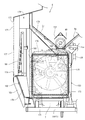
- FIG. 1 It is front sectional drawing which shows the positional relationship of a grain tank and a threshing apparatus. It is a top view which shows the internal structure of a cover duct body. It is a partially cutaway left view which shows the communication structure of a side part duct and a front part duct. It is front sectional drawing which shows the communication structure of a side part duct and a front part duct.
- the left side in the forward direction of the traveling machine body 1 is simply referred to as the left side
- the right side in the forward direction is also simply referred to as the right side.
- the combine according to the embodiment includes a traveling machine body 1 supported by a pair of left and right iron crawler belts 2 as a traveling portion.
- a reaping device 3 for capturing uncut cereal grains such as rice (or wheat, soybeans or corn) is mounted by a single-acting lifting hydraulic cylinder 4 so as to be adjustable up and down. ing.
- a cab 5 as a driving part on which an operator gets on board is mounted.
- a Glen tank 6 for storing the grain after threshing is disposed behind the cab 5.
- An engine 7 as a power source is disposed behind the Glen tank 6.
- a grain discharge auger 8 is provided on the right side of the rear part of the Glen tank 6 so as to be able to turn.
- the grain in the Glen tank 6 is carried out, for example, to a truck bed, a container, or the like from the throat throw opening 8a at the tip of the discharge auger 8.
- a threshing device 9 for threshing the harvested cereal meal supplied from the harvesting device 3.
- a grain sorting mechanism 10 for performing swing sorting and wind sorting is arranged.
- the reaping device 3 includes a feeder house 11 that communicates with the handling port 9 a at the front of the threshing device 9, and a horizontally long bucket-like grain header 12 that is provided continuously at the front end of the feeder house 11.
- a scraping auger 13 is rotatably supported in the grain header 12.
- a take-up reel 14 with a tine bar is disposed above the front portion of the take-up auger 13.
- a clipper-shaped cutting blade 15 is disposed in front of the grain header 12.
- a weeding body 16 is provided on both the left and right sides of the front portion of the grain header 12.
- a supply conveyor 17 is provided in the feeder house 11.
- a beater 18 for passing cereals is provided between the feed end of the supply conveyor 17 and the handling port 9a.
- the lower surface part of the feeder house 11 and the front end part of the traveling machine body 1 are connected via the lifting hydraulic cylinder 4, and the reaping device 3 moves up and down by the lifting hydraulic cylinder 4.
- the tip side of the uncut grain culm between the left and right weed bodies 16 is scraped by the take-up reel 14, and the heel side of the uncut grain pod is cut by the cutting blade 15.
- the grain headers 12 are collected in the vicinity of the center of the left and right width.
- the whole amount of the harvested cereal grains of the grain header 12 is conveyed by the supply conveyor 17 and is input to the handling port 9 a of the threshing device 9 by the beater 18.
- the grain header 12 is provided with a horizontal control hydraulic cylinder 19 for rotating the grain header 12 about the horizontal control fulcrum shaft 19a, and the grain header 12,
- the cutting blade 15 and the take-up reel 14 are supported horizontally with respect to the field scene.
- a handling cylinder 21 is rotatably provided in a handling chamber of the threshing device 9.
- a handling cylinder 21 is pivotally supported on a handling cylinder shaft 20 extended in the front-rear direction of the traveling machine body 1.
- a receiving net 24 (concave) for allowing the grains to leak is stretched below the handling cylinder 21.
- a spiral (screw blade-shaped) intake blade 25 projects outward in the radial direction.
- the harvested cereal mash introduced from the handling port 9 a is kneaded between the handling cylinder 21 and the receiving net 24 while being conveyed toward the rear of the traveling machine body 1 by the rotation of the handling cylinder 21. Threshed.
- the threshing of grains or the like smaller than the mesh of the receiving net 24 leaks from the receiving net 24.
- the sawdust and the like that do not leak from the receiving net 24 are discharged from the dust outlet at the rear of the threshing device 9 to the field by the conveying action of the handling cylinder 21.
- a plurality of dust feeding valves (not shown) for adjusting the conveying speed of threshing in the handling chamber are pivotally mounted on the upper side of the handling cylinder 21 so as to be rotatable.
- the conveying speed (residence time) of threshing in the handling chamber can be adjusted according to the variety and properties of the harvested cereal.
- a rocking sorter 26 for specific gravity sorting having a grain pan, chaff sheave, grain sheave, Strollac and the like is provided as the grain sorting mechanism 10 disposed below the threshing device 9, a rocking sorter 26 for specific gravity sorting having a grain pan, chaff sheave, grain sheave, Strollac and the like is provided.
- the grain sorting mechanism 10 includes a tang fan 29 that supplies sorting wind.
- the threshing that has been threshed by the handling cylinder 21 and leaked from the receiving net 24 is the first of the grains (fine grains, etc.) by the specific gravity sorting action of the swing sorter 26 and the wind sorting of the Kara fan 29, Sorted into second crops such as grain with branch stems and sawdust.
- a first conveyor mechanism 30 and a second conveyor mechanism 31 are provided below the rocking sorter 26, as the grain sorting mechanism 10, a first conveyor mechanism 30 and a second conveyor mechanism 31 are provided below the rocking sorter 26, as the grain sorting mechanism 10, a first conveyor mechanism 30 and a second conveyor mechanism 31 are provided below the rocking sorter 26, as the grain sorting mechanism 10, a first conveyor mechanism 30 and a second conveyor mechanism 31 are provided below the rocking sorter 26, as the grain sorting mechanism 10, a first conveyor mechanism 30 and tang fan 29, the first item such as the grain dropped from the swing sorter 26 is collected in the glen tank 6 by the first conveyor mechanism 30 and the cereal conveyor 32.
- a second thing such as a grain with a branch is returned to the sorting start end side of the swing sorting board 26 via the second conveyor mechanism 31 and the second reduction conveyor 33 and is re-sorted by the swing sorting board 26.
- the sawdust and the like are discharged from the dust outlet 34 at the rear of the traveling machine body 1 to the field.
- the cab 5 is provided with a control column 41 and a driver seat 42 on which an operator sits.
- the control column 41 includes left and right speed change levers 43 and 44 as control levers for changing the course of the traveling machine body 1 and changing the moving speed, and the reaping device 3 is moved up and down by tilting in the front-rear direction.
- a cutting posture lever 45 for tilting in the left-right direction to raise and lower the take-up reel 14, an accelerator lever 46 for controlling the rotation of the engine 7, and a grain discharge lever 47 for operating the grain discharge auger 8 are arranged.
- illustration is abbreviate
- a roof 49 for awning is attached to the upper side of the cab 5 via a support column 48.
- the left and right track frames 50 are disposed on the lower surface side of the traveling machine body 1.
- the track frame 50 includes a drive sprocket 51 that transmits the power of the engine 7 to the crawler belt 2, a tension roller 52 that maintains the tension of the crawler belt 2, a plurality of track rollers 53 that hold the ground side of the crawler belt 2 in a grounded state, An intermediate roller 54 for holding the non-grounding side of the crawler belt 2 is provided.
- the rear side of the crawler belt 2 is supported by the drive sprocket 51, the front side of the crawler belt 2 is supported by the tension roller 52, the grounding side of the crawler belt 2 is supported by the track roller 53, and the non-grounded side of the crawler belt 2 is supported by the intermediate roller 54 To be configured.
- a bottom feed conveyor 60 disposed at the bottom of the Glen tank 6 and a vertical feed conveyor 61 disposed at the rear of the Glen tank 6 are provided.
- the left and right bottom feed conveyors 60 extend in the front-rear direction at the bottom of the grain tank 6 and convey the grains at the bottom of the grain tank 6 toward the lower end side of the vertical feed conveyor 61 provided vertically.
- the vertical feed conveyor 61 is extended in the vertical direction at the rear part of the grain tank 6, and conveys the grain from the upper end side of the vertical feed conveyor 61 toward the feed start end side of the grain discharge auger 8 on the right side of the grain tank 6. .
- the grain in the Glen tank 6 is conveyed to the throat throwing port 8a at the tip (feed end side) of the grain discharge auger 8.
- the grain discharge auger 8 is supported on the upper end side of the vertical feed conveyor 61 so as to be rotatable up and down, and is configured so that the side of the grain discharge auger 8 that is the feed end side of the grain discharge auger 8 can be raised and lowered. Moreover, it is comprised so that the hull spout 8a side of the grain discharge auger 8 can be moved around the conveyor shaft center (horizontal direction) of the vertical feed conveyor 61. That is, the side of the heel throw 8a is moved to the lower side of the front part of the traveling machine body 1, and the grain discharge auger 8 is stored in the right side of the cab 5 and the grain tank 6 via the auger rest 8b.
- the side of the grain discharge auger 8 which is the feed terminal side, is raised, the side of the traveling machine body 1 is moved to the side or rear of the traveling machine body 1, and the side of the traveling machine body 1 is moved backward.
- the grain discharge auger 8 is protruded, and the grain thrower 8a is made to face the loading platform or container of the truck so that the grains in the grain tank 6 are carried out to the loading platform or container of the truck.
- the threshing device 9 includes a handling cylinder 21 for threshing threshing, a rocking sorter 26 for selecting a shed product falling below the handling cylinder 21, and a tang fan 29.
- the front side of the handling cylinder 21 faces the handling port 9a communicating with the feeder house 11, and the rear side of the handling cylinder 21 faces the dust outlet 34 at the rear of the threshing device 9. That is, the rear side of the handling cylinder 21 protrudes further rearward than the rear end of the receiving net 24 that causes the grains to leak.
- a dust exhaust port 34 is provided at the lower rear side of the handling cylinder 21 (an opening portion without the receiving net 24).
- the rotation axis of the handling cylinder 21 extends along the traveling direction (front-rear direction) of the traveling machine body 1.
- the threshed material threshed by the handling cylinder 21 by the inclined plate 119 is brought to the left and right center side of the swing sorter 26.
- the harvested cereal mash that has been introduced into the handling port 9 a of the threshing device through the feeder house 11 and the beater 18 from the reaping device 3 is threshed by the handling cylinder 21.
- the swing sorter 26 located below the receiving net 24 is configured to be able to swing back and forth in a diagonally forward and downward direction via a swing link 35.
- the swing sorter 26 includes a grain pan 36 positioned below the front of the receiving net 24, a movable chaff sheave 37 and a fixed chaff sheave 38 for adjusting the amount of grain leakage, and a movable chaff sheave 37 and the first conveyor mechanism 30.
- the arrangement includes a grain sheave 39 and a stroller rack 40 connected to the rear end side of the fixed chaff sheave 38.
- the cereals on the chaff sheaves 37 and 38 are subjected to specific gravity sorting by the chaff sheaves 37 and 38 themselves, and are separated into grains and sawdust by receiving a sorting wind flowing backward from the tang fan 29.
- Kernel (first thing) that has fallen from the movable chaff sheave 37 and the Glen sheave 39 is first collected by the conveyor mechanism 30 while removing the dust in the sorting air of the Kara fan 29.
- the grain taken out from the first conveyor mechanism 30 is carried into and collected in the Glen tank 6 through the cereal conveyor 32.
- the second object that has failed to pass through the movable chaff sheave 37 and the Glen sheave 39 and the second object that has dropped from the fixed chaff sheave 38 are collected by the second conveyor mechanism 31 that is the rearmost of the conveyor mechanism 30.
- the second items collected by the second conveyor mechanism 31 are returned to the upper surface side of the swing sorter 26 via the second reduction conveyor 33 and re-sorted.
- the relatively heavy sawdust on the chaff sheaves 37 and 38 is discharged from the dust outlet 34 to the outside of the machine via the stroller 40.
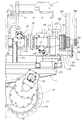
- a hydraulic pump case 66 for traveling speed change having a pair of swash plate variable type left and right traveling hydraulic pumps 65 is provided.
- the engine 7 is mounted on the upper surface of the right rear portion of the traveling machine body 1, and the hydraulic pump case 66 is disposed on the upper surface of the traveling machine body 1 on the left side of the engine 7.
- left and right reduction gear cases 63 are provided at the rear ends of the left and right track frames 50, respectively.
- a traveling hydraulic motor 69 is disposed in each of the left and right reduction gear cases 63.
- a travel drive input shaft 64 projecting rearward from the hydraulic pump case 66 and an output shaft 67 projecting rearward from the engine 7 are connected via an engine output belt 231.
- the engine 7 and the hydraulic pump case 66 are provided on the upper surface side of the traveling machine body 1 on the rear side of the threshing device 9, and the hydraulic pump case 66 is disposed between the engine 7 and the threshing device 9.
- a charge pump 68 for driving the lifting hydraulic cylinder 4 and the like is also provided on the same axis 64 as the traveling hydraulic pump 65. Further, a working hydraulic pump 70 for operating the lifting hydraulic cylinder 4 or the horizontal control hydraulic cylinder 19 is disposed in the engine 7, and the charge pump 68 and the working hydraulic pump 70 are connected to the engine 7 in the same manner as the traveling hydraulic pump 65. It is comprised so that it may drive.
- the drive output of the engine 7 is transmitted to the left and right traveling hydraulic pump 65 via the output shaft 67.
- the left and right traveling hydraulic motors 69 are individually driven by the left and right traveling hydraulic pumps 65, and the left and right crawler belts 2 are moved forward and backward by the left and right traveling hydraulic motors 69. Further, the rotational speed of the left and right traveling hydraulic motor 69 is controlled, and the rotational speed of the left and right crawler belts 2 driven by the left and right traveling hydraulic motor 69 is varied to change the moving direction (traveling path) of the traveling machine body 1 and It is configured to perform direction changes on the ground.
- a pair of left and right traveling hydraulic motors 69 are hydraulically connected to the left and right traveling hydraulic pumps 65 via a closed loop hydraulic circuit.
- the left and right crawler belts 2 are driven in the forward direction or the reverse direction via the drive sprocket 51 by the left and right traveling hydraulic motor 69.
- the operator operates the left and right shift levers 43 and 44 to adjust the swash plate angles (shift control) of the left and right traveling hydraulic pumps 65, respectively.
- the left and right crawler belts 2 are driven independently from each other, and the traveling machine body 1 is configured to move forward or backward.
- a handling cylinder drive case 71 that supports a threshing input shaft 72 is provided.
- a threshing input shaft 72 is connected to the traveling drive input shaft 64 via a threshing drive belt 232.
- the power of the engine 7 is transmitted from the travel drive input shaft 64 to the threshing input shaft 72 via the threshing clutch 233 also serving as a tension roller and the threshing drive belt 232.
- the threshing clutch 233 is controlled to be turned on and off by the operator's lever operation.
- a threshing input shaft 72 is connected to one end side (rear end side) of the barrel 20 via a barrel drive belt 234.
- a cutting selection input case 73 is provided on the front wall of the threshing device 9.
- a cutting selection input shaft 74 is pivotally supported on the cutting selection input case 73.
- One end side (right end portion) of the cutting selection input shaft 74 is connected to the other end side (front end side) of the barrel 20 via a bevel gear 75.
- the other end side (left end portion) of the cutting selection input shaft 74 is connected to the left end portion of the beater shaft 82 on which the beater 18 is pivotally supported via the beater drive belt 238.
- the left end portion of the beater shaft 82 is connected to the left end portion of the hot shaft 76 supporting the hot fan 29 via a selection input belt 235.
- a tang shaft 76 is connected to the left end of the first conveyor shaft 77 of the first conveyor mechanism 30 and the left end of the second conveyor shaft 78 of the second conveyor mechanism 31 via a conveyor drive belt 237.
- a left end portion of a second conveyor shaft 78 is connected to a left end portion of a crank-like swing drive shaft 79 pivotally supported by the rear portion of the swing sorting plate 26 via a swing sorting belt 236.
- the cereal conveyor 32 is driven via the first conveyor shaft 77, and the first selected grain of the first conveyor mechanism 30 is collected in the Glen tank 6.
- the second reduction conveyor 33 is driven via the second conveyor shaft 78, and the second selected grain mixed with the sawdust from the second conveyor mechanism 31 is returned to the upper surface side of the rocking sorter 26.
- the combination of the sorting input belt 235, the swing sorting belt 236, and the conveyor drive belt 237 corresponds to a sorting drive belt for transmitting power to the grain sorting mechanism 10.
- the left end portion of the cutting input shaft 89 on which the feed end side of the supply conveyor 17 is pivotally supported is connected to the left end portion of the beater shaft 82 via a cutting drive belt 241 and a cutting clutch 242.
- the right end of the cutting input shaft 89 is connected to the header drive shaft 91 provided on the grain header 12 via the header drive chain 90.
- a header drive shaft 91 is connected to a drive shaft 93 that supports the drive auger 13 via a drive drive chain 92.
- a header drive shaft 91 is coupled to a reel shaft 94 that supports the take-up reel 14 via an intermediate shaft 95 and reel drive chains 96 and 97.
- the cutting blade 15 is connected to the right end portion of the header driving shaft 91 through a cutting blade driving crank mechanism 98.
- the feed conveyor 17, the auger 13, the hoisting reel 14, and the cutting blade 15 are driven and controlled so as to continuously mow the tip of the uncut grain culm in the field. It is configured.
- a reaping device 3 a threshing device 9 having a handling cylinder 21, and a traveling machine body 1 having a driver's seat 42 are provided.
- the engine 7 is mounted on the rear part of the traveling machine body 1, and the power of the engine 7 is transmitted to the rear end side of the handling cylinder 20 on which the handling cylinder 21 is pivotally supported.
- the power of the engine 7 is transmitted from the front end side of the handling cylinder shaft 20 to the cutting device 3 and the beater 18, the beater 18 is driven via the handling cylinder shaft 20, and the cutting device 3 is driven via the beater 18.
- the large reaping device 3 having a wide cutting width can be stably supported, and the front-rear balance of the traveling machine body 1 can be improved. That is, it is possible to improve harvesting workability in wet fields or mobility on rough roads. Further, since the power of the engine 7 is transmitted to the beater 18 and the reaping device 3 using the handling cylinder 20, even if the reaping device 3 and the engine 7 are provided apart from each other, the engine 7 is connected to the beater 18 or the reaping device 3.
- the transmission path can be easily configured. That is, the maintenance workability of the drive structure such as the reaping device 3 or the threshing device 9 can be improved.
- the rear end side of the bottom feed conveyor shaft 103 of the bottom feed conveyor 60 is connected to the rear end portion of the travel drive input shaft 64 via the grain discharge belt 244 and the grain discharge clutch 245.
- One end side of the lower mediation shaft 105 is connected to the rear end portion of the bottom feed conveyor shaft 103 via a longitudinal feed drive chain 104.
- the other end side of the mediation shaft 105 is connected to the lower end side of the vertical feed conveyor shaft 106 of the vertical feed conveyor 61 via a bevel gear mechanism 107.
- One end side of the upper intermediate shaft 109 is connected to the upper end side of the vertical feed conveyor shaft 106 via a bevel gear mechanism 108.
- One end side of the grain discharge shaft 111 is connected to the other end side of the upper mediation shaft 109 via the grain discharge drive chain 110.
- the feed start end side of the discharge auger shaft 112 of the grain discharge auger 8 is connected to the other end side of the grain discharge shaft 111 via a bevel gear mechanism 113.
- front and rear grain discharge ports 221 and 222 are provided at the bottom of the Glen tank 6.
- the wrinkle receiving base 223 is arrange
- An operator other than the operator of the driver's seat 42 rides on the saddle cradle 223 in a state where the saddle cradle 223 is supported in a horizontal working posture, and attaches a saddle bag to a saddle catcher (not shown).
- the grain in the Glen tank 6 is discharged into the bag.
- the straw bag filled with the grain is dropped from the straw catcher 223 to the field and collected.
- the grains in the grain tank 6 can be discharged without interrupting the mowing and threshing operation. That is, compared with the work of discharging the grain in the grain tank 6 from the grain discharge auger 8, there is almost no need to interrupt the mowing and threshing work. Work efficiency can be improved.
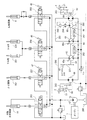
- the combine hydraulic structure and the travel drive structure will be described with reference to FIGS.
- the hydraulic actuator the harvesting lifting hydraulic cylinder 4, the horizontal control hydraulic cylinder 19, the left and right reel lifting hydraulic cylinders 251 that support the take-up reel 14 so as to be lifted and lowered, and the grain
- An auger lifting / lowering hydraulic cylinder 252 that supports the discharge auger 8 to be movable up and down is provided.
- the working hydraulic pump 70 is hydraulically connected to the horizontal control hydraulic cylinder 19 through a horizontal control electromagnetic hydraulic valve 253 that is controlled by operation of the horizontal control switch 254.
- the horizontal control switch 254 When the operator operates the horizontal control switch 254 to operate the horizontal control hydraulic cylinder 19, the left-right inclination of the traveling machine body 1 is maintained at a horizontal or arbitrary inclination.
- a horizontal control switch is provided at the upper end of the cutting posture lever 45.
- the working hydraulic pump 70 is hydraulically connected to the cutting lift hydraulic cylinder 4 via the cutting lift manual hydraulic valve 255.
- the cutting lifting / lowering hydraulic cylinder 4 is actuated so that the operator moves the cutting device 3 up and down to an arbitrary height (for example, cutting height or non-working height). It is configured.
- the working hydraulic pump 70 is hydraulically connected to the reel lifting hydraulic cylinder 251 through the reel lifting manual hydraulic valve 256.
- the reel lifting hydraulic cylinder 251 is actuated, and the operator lifts and lowers the take-up reel 14 to an arbitrary height to harvest the uncut grain culm on the field. .
- the working hydraulic pump 70 is hydraulically connected to the auger lifting hydraulic cylinder 252 via the auger lifting manual hydraulic valve 257.
- the auger lifting / lowering hydraulic cylinder 252 is operated, and the operator moves the cocoon throwing port 8a of the grain discharging auger 8 up and down to an arbitrary height.
- the grain discharge auger 8 is rotated in the horizontal direction by an electric motor (not shown), and the cocoon throwing port 8a is moved in the horizontal direction.
- the culling spout 8a is positioned above the truck bed or container, and the grains in the grain tank 6 are discharged into the truck bed or container.
- left and right traveling hydraulic motors 69 are hydraulically connected to the left and right traveling hydraulic pumps 65 via left and right closed hydraulic circuits 261, respectively.
- the left and right speed change levers 43 and 44 are connected to the output adjusting swash plate 65a of the left and right traveling hydraulic pumps 65 via a servo valve mechanism 262, respectively, and are proportional to the front and rear tilt angles of the left and right speed change levers 43 and 44.
- the support angle of the output adjusting swash plate 65a is changed.
- the left and right traveling hydraulic motors 69 are respectively driven by the left and right traveling hydraulic pumps 65, and the driving force of the left and right traveling hydraulic motors 69 is transmitted to the left and right crawler belts 2 via the reduction gear mechanism 263 of the reduction gear case 63, respectively.
- the left and right crawler belts 2 are driven forward or backward.
- the traveling machine body 1 can move straight in the forward direction at a vehicle speed proportional to the tilt angle of the left and right speed change levers 43 and 44.
- the left and right speed change levers 43 and 44 can be moved straight in the backward (reverse) direction at a vehicle speed proportional to the tilt angle of the left and right speed change levers 43 and 44.
- the traveling machine body 1 can be swung in the left-right direction with a turning radius proportional to.
- a left and right closed hydraulic circuit 261 is connected to the high pressure oil discharge side of the charge pump 68 via an oil cooler 264 and a line filter 265 so that the hydraulic oil in the oil tank 266 is supplied to the left and right closed hydraulic circuits 261. It is configured.
- An oil tank 266 is mounted on the upper surface of the traveling machine body 1 on the left side of the fuel tank 267 of the engine 7, and the driver's seat 42 is disposed above the fuel tank 267 via a seat frame 268.
- the hydraulic pump case 66 in which the left and right traveling hydraulic pumps 65 are incorporated is mounted on the engine 7 mounted on the right upper surface of the rear portion of the traveling aircraft 1 and on the upper left surface of the traveling aircraft 1.
- the right side wall body of the threshing device 9 that has been made, it is fixed on the upper surface side of the traveling machine body 1 via the front support body 271 and the rear support body 272.
- a U-shaped intermediate portion of the front support body 271 is fastened to the upper surface of the traveling machine body 1 with bolts 273.
- the left and right side surfaces of the hydraulic pump case 66 are fastened with bolts 274 to both U-shaped ends of the front support 271.
- the front portion of the hydraulic pump case 66 in which the charge pump 68 is disposed is supported on the traveling machine body 1 by the front support body 271.
- the bottom surface side of the rear support body 272 is fastened to the mounting base 275 on the upper surface side of the traveling machine body 1 with bolts 276.
- the rear side of the hydraulic pump case 66 is fastened to the front side of the rear support 272 with bolts 277.
- a support arm body 272a extends rearward from the rear surface of the rear support body 272, and the lower end side of the rear bearing body 278 is fastened to the rear end portion of the support arm body 272a with a bolt 279.
- the rear end side of the travel drive input shaft 64 protrudes rearward from the rear surface of the hydraulic pump case 66, and the travel drive input shaft 64 is passed through the rear support body 272 and the rear bearing body 278.
- a grain discharge drive pulley 282 around which the grain discharge belt 244 is wound is pivotally supported at the rear end portion of the travel drive input shaft 64 protruding rearward from the rear bearing body 278. That is, an engine output transmission pulley 280, a threshing output transmission pulley 281 and a grain discharge driving pulley 282 as counter pulleys are pivotally supported on a travel drive input shaft 64 as a counter shaft.
- an engine output pulley 283 is pivotally supported on the output shaft 67 of the engine 7, and the engine output belt 231 is wound between the engine output transmission pulley 280 and the engine output pulley 283.
- a large-diameter threshing input pulley 284 is pivotally supported on one end side of the threshing input shaft 72, and a threshing driving belt 232 is wound between the threshing output transmission pulley 281 and the large-diameter side threshing input pulley 284.
- a small-diameter threshing input pulley 285 is pivotally supported on the other end side of the threshing input shaft 72, and a barrel driving belt 234 is disposed between the barrel input pulley 286 on the barrel shaft 20 and the small-diameter threshing input pulley 285. Wrap around. Further, a grain discharge pulley 287 is pivotally supported on the rear end side of the bottom feed conveyor shaft 103, and a grain discharge belt 244 is wound between the grain discharge drive pulley 282 and the grain discharge pulley 287.
- the engine output pulley 283 on the output shaft 67 of the engine 7, the counter pulleys 280 to 282 on the counter shaft 64, and the threshing input pulley 284 of the threshing device 9 can transmit power to the rear side of the traveling machine body 1. They are arranged together.
- the driving force output from the engine 7 is branched and transmitted by the travel drive input shaft 64 as a counter shaft. That is, the output of the engine 7 is transmitted from the travel drive input shaft 64 to the left and right travel hydraulic pumps 65. Further, the output of the engine 7 is transmitted from the threshing output transmission pulley 281 on the traveling drive input shaft 64 to the barrel shaft 20 of the threshing device 9 via the threshing drive belt 232 and the barrel driving belt 234. On the other hand, the output of the engine 7 is transmitted from the grain discharge drive pulley 282 on the travel drive input shaft 64 to the grain discharge auger 8 via the grain discharge belt 244.
- the engine 7 is mounted on the rear portion of the traveling machine body 1
- the threshing device 9 and the grain tank 6 are provided on the traveling machine body 1
- the reaping device is disposed in front of the threshing device 9.
- a travel drive input shaft 64 as a counter shaft parallel to the output shaft 67 of the engine 7 and at the same height position, an engine output pulley 283 on the output shaft 67, and a counter on the counter shaft 64 Since the pulleys 280 to 282 and the threshing input pulley 284 of the threshing device 9 are disposed flush with the rear surface of the traveling machine body 1 (collectively disposed), the threshing that transmits power from the engine 7 to the threshing device 9
- the drive belt 232 or the like can be compactly assembled to the rear surface side of the engine 7 or the rear surface side of the threshing device 9.
- the belt drive structure for transmitting power from the engine 7 to the threshing device 9 or the grain tank 6 can be made compact and simplified. Further, the engine output transmission pulley 280 (counter pulley) around which the output belt 231 of the engine 7 is wound can be arranged at a position where the vibration of the engine 7 is reduced.
- the left and right traveling hydraulic pumps 65 and the left and right traveling hydraulic motors 69 are provided, and the left and right traveling hydraulic motors 69 are operated by the left and right traveling hydraulic pumps 65. Since the left and right traveling hydraulic pumps 65 are disposed on the traveling drive input shaft 64, the traveling hydraulic pump 65 can be installed compactly in the engine room adjacent to the engine 7. Further, the traveling hydraulic pump 65 can be easily air-cooled by the cooling air of the engine 7. The driving efficiency of the crawler belt 2 can be improved while the hydraulic piping structure of the left and right traveling hydraulic pumps 65 and the left and right traveling hydraulic motors 69 can be simplified.
- the engine 7 is mounted on the traveling machine body 1 below the rear part of the Glen tank 6, and the grain discharge pulley 287 of the Glen tank 6 is attached to the rear surface of the traveling machine body 1.
- , 281, 282 are arranged flush with each other, so that the rear part of the traveling machine body 1 is opened, so that the grain discharge belt 244 of the grain tank 6 can be replaced or maintained from the rear side of the traveling machine body 1. Easy to execute. While the power transmission structure to the Glen tank 6 can be simplified, handling workability can be improved.
- a beater 18 and a beater shaft 82 for passing cereals are arranged below a cutting selection input shaft 74 that protrudes leftward and rightward from the cutting selection input case 73 at the front of the threshing device 9. Yes.
- Power is transmitted from the cutting selection input shaft 74 to the beater shaft 82 via the beater drive belt 238.
- the power transmitted to the beater shaft 82 is distributed by being distributed back and forth on the left wall side of the threshing device 9 toward the reaping device 3 and the grain sorting mechanism 10.
- power is transmitted from the beater shaft 82 to the cutting input shaft 89 that pivotally supports the feed end side of the supply conveyor 17 via the cutting drive belt 241 and the cutting clutch 242, and to the cut shaft through the selection input belt 235. Power is transmitted to 76.
- the cutting input shaft 89 and the tang shaft 76 are located further below the beater shaft 82.
- the outer surface side of the left wall in the threshing device 9 is covered with a total of four cover bodies 121 to 124 arranged vertically and front and back.
- These cover bodies 121 to 124 are basically for protecting the movable parts (pulleys, belts, etc.) on the left side of the combine.
- the lower front cover body 123 covers and conceals the movable parts of the cutting input shaft 89 and the red pepper shaft 76, and the lower rear cover body 124 conceals the movable parts behind the red pepper shaft 76 in the grain sorting mechanism 10.
- the upper front cover body 121 covers the movable parts of the cutting and sorting input shaft 74 and the beater shaft 82, and the upper rear cover body 122 as a lateral plate covers the left side portion of the handling cylinder 21.
- the lower front and rear cover bodies 123 and 124 and the upper front cover body 121 are detachably mounted on the outer surface side of the left side wall body in the threshing device 9.
- the upper rear cover body 122 is provided so as to be able to open and close in the horizontal direction with the vertical axis 125 on the front side as a rotation fulcrum. That is, the pair of upper and lower horizontal frames 126 that are strength members of the upper rear cover body 122 has a front end side protruding from the front end surface of the upper rear cover body 122.
- the projecting end portions of the horizontal frames 126 are pivotally mounted on the vertical axis 125 at two upper and lower support stay portions 127 provided on the front outer surface side of the left wall.
- a rectangular opening 128 is formed on the upper side of the left wall of the threshing device 9 so that the handling cylinder 21 can face.
- the rectangular opening 128 of the threshing device 9 is closed, and if the upper rear cover body 122 is opened, the handling cylinder 21 and the right receiving net 24b facing the rectangular opening 128 (details) Will be exposed later).
- the movable part of the cutting selection input shaft 74 and the beater shaft 82, the movable part of the cutting input shaft 89, and the movable part of the grain sorting mechanism 10 are arranged around the upper rear cover body 122. And is provided so as to bypass the upper rear cover body 122. Therefore, although both the movable parts and the upper rear cover body 122 are on the left wall side of the threshing device 9, the opening and closing rotation around the vertical axis 125 of the upper rear cover body 122 interferes with the movable parts. Absent.
- the receiving network 24 of the embodiment is a concave type formed in a lattice shape, and is configured by a combination of a pair of receiving network portions 24a and 24b that can be divided in the left-right direction.
- the right receiving net portion 24b near the right wall of the threshing device 9 is fixed to the front wall, the right wall, and the like of the threshing device 9.
- the left receiving mesh portion 24 a located near the upper rear cover body 122 is fixed to the inner surface side of the upper rear cover body 122 so as to rotate integrally with the upper rear cover body 122.
- a front and rear longitudinal locking pin body 129 is provided on the outer surface side of the rear wall body in the threshing device 9.
- a hook lever 130 that is detachably hooked and engaged with the locking pin body 129 on the rear wall body side is provided so as to be rotatable.
- the hook lever 130 is always biased by a tension spring 131 in a direction in which the hook lever 130 is hooked and engaged with the locking pin body 129.
- An operation hole 132 through which the handle shaft portion of the hook lever 130 passes is provided on the rear side of the upper rear cover body 122.
- the upper front cover body 121 When opening the upper rear cover body 122, the upper front cover body 121 is removed in advance, and then the hook lever 130 is rotated in the disengagement direction to open and rotate the upper rear cover body 122 leftward. You can do it. Then, the upper rear cover body 122 rotates around the vertical axis together with the left receiving mesh portion 24a, and the handling cylinder 21 and the right receiving mesh portion 24b in the threshing device 9 are exposed. When closing the upper rear cover body 122, it is only necessary to push the free end side of the upper rear cover body 122 toward the threshing device and to close and rotate it in the right direction.
- the cutting device 3 including the cutting blade 15 and the threshing device 9 including the handling cylinder 21 and the receiving net 24 are provided, and the threshing device 9 is connected to the threshing device 9 via the feeder house 11 and the beater 18. It is a normal combine that supplies the harvested cereal rice cake, and a grain tank 6 is arranged on one side of the left and right sides of the threshing device 9, and the left and right other sides of the threshing device 9 are opened and closed around a vertical axis 125.
- a possible lateral side plate 122 is provided, and the handling cylinder 21 and the receiving net 24 in the threshing device 9 are exposed by opening and turning the lateral side plate 122, so that the mounting height of the lateral side plate 122 is almost changed. Without this, the lateral plate 122 can be opened and closed. For this reason, it is easy to open and close the lateral side plate 122 regardless of the height of the operator, and there is no inconvenience of the opening and closing operation as in the prior art. Further, since the lateral plate 122 is configured to open / close and rotate around the vertical axis 125, that is, to rotate horizontally, the lateral plate 122 is opened even without an actuator such as a gas cylinder as in the prior art. Can be maintained. For this reason, it is not necessary to secure the space for arranging the actuator, the number of parts can be reduced, and the manufacturing cost can be reduced.
- the receiving net 24 is configured by a combination of a pair of receiving net parts 24 a and 24 b that can be divided in the left-right direction, and the left receiving net part 24 a near the lateral side plate 122 rotates integrally with the lateral side plate 122.
- the left receiving mesh portion 24a is also opened and rotated around the longitudinal axis 125 together with the lateral side plate 122. become. For this reason, the side space around the handling cylinder 21 and the receiving net 24 in the threshing device 9 can be greatly opened, and cleaning work and maintenance work are easy to perform.
- a grain selection mechanism 10 is provided below the lateral plate 122 in the threshing device 9, and the beater 18 is disposed between the feeder house 11 and the threshing device 9.
- the power of the engine 7 that is disposed below the front end side of the front and rear longitudinal barrel shaft 20 that pivotally supports and is mounted on the rear portion of the traveling machine body 1 is transmitted to the beater 18 via the barrel shaft 20,
- the power transmitted to the beater 18 is distributed and distributed back and forth on the other side of the threshing device 9 toward the reaping device 3 and the grain sorting mechanism 10.
- both the power transmission system to the grain sorting mechanism 10 and the lateral plate 122 are on the other side of the threshing device 9, the power transmission system to the reaping device 3 and the grain sorting mechanism 10 is provided. Bypassing the side plate 122 It is is will be. For this reason, both the maintenance work of the handling cylinder 21 and the receiving net 24 and the maintenance work for the power transmission system to the harvesting device 3 and the grain sorting mechanism 10 are performed from the opposite side of the Glen tank 6 installation side. It can be executed easily and maintenance workability is improved.
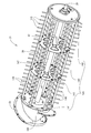
- the handling cylinder 21 of the embodiment includes a plurality of front and rear support bodies 140 formed in a disc shape, and a plurality of bone frames provided at appropriate intervals in the circumferential direction. 145 to form a substantially cage shape.
- the support body 140 includes a front support body 141, a rear support body 142, and two intermediate support bodies 143.
- the handling shaft 20 penetrates the center of each support 140 (141 to 143) in a skewered manner, and each support 140 (141 to 143) is fixed so as to rotate integrally with the handling shaft 20. .
- a frustoconical handle plate 144 is provided on the front side of the front support plate 141.
- a take-in blade 25 protrudes from the outer peripheral side of the handling plate 144.
- Each bone frame 145 extends in parallel with the handle barrel shaft 20 and is connected to the handle barrel shaft 20 via each support 140 so as to rotate integrally.
- the bone frame 145 is a bar having a polygonal cross section.
- the bone frame 145 of the embodiment is made of a rectangular pipe material (see FIG. 16).
- Each bone frame 145 is provided with a large number of rod-like teeth 146 protruding outward in the radial direction in the longitudinal direction along the barrel axis 20.
- a round bar-shaped (circular cross section) bar-shaped tooth 146 is employed.
- each bone frame 145 when viewed from the axial direction of the handle cylinder 20, one longitudinal side surface 145 a (radially outward side surface) of each bone frame 145 is along the rotational tangent direction of the handle cylinder 21.
- a rod-shaped tooth 146 is erected on the one longitudinal side surface 145a.
- the two grain portions outward in the radial direction in the bone frame 145 and the side face facing the rotation direction of the handling cylinder 21 can promote the threshing action of the harvested cereal.
- the grain By the interaction of each bar-shaped tooth 146 and each bone frame 145, the grain can be efficiently divided or knocked down from the harvested cereal.
- a plurality of through holes 147 are formed around the penetrating portion of the handling cylinder shaft 20 in the intermediate support 143 so as to surround the handling cylinder axis 20.
- Each of these through holes 147 is formed to reduce the weight of the intermediate support 143, but also functions as an escape route for the harvested cereals that have entered the basket-like internal space of the handling cylinder 21. For this reason, the residence time of the harvested cereal mash that has entered the internal space can be shortened, and it is possible to contribute to the improvement of the discharge efficiency of the threshed cereal mash (excretion) that has been threshed. That is, it is possible to reduce the amount of waste processing in the grain sorting mechanism 10 and to achieve reduction in the threshing load and improvement in threshing and sorting performance.
- the reaping device 3 having the cutting blade 15 and the threshing device 9 having the handling cylinder 21 are provided, and the reaped cereal meal is supplied from the reaping device 3 to the threshing device 9 via the feeder house 11.
- the handling cylinder 21 extends in parallel with the handling cylinder axis 20 and has a plurality of bone frames 145 having a polygonal cross section aligned in the circumferential direction of the handling cylinder 21, and the bone frame 145 is external to the bone frame 145. Since each bone frame 145 is supported by the handle barrel shaft 20 via a support plate 140, the rod handle teeth 146 are provided not only for the rod handle teeth 146.
- each bone frame 145 having a polygonal cross section can promote the threshing action of the harvested cereal. Since each of the bone frames 145 has a polygonal cross section, it is effective for dividing or knocking down the grains from the harvested cereal meal. Compared to the prior art, each bone frame 145 functions more as an auxiliary member for the threshing process. Therefore, both cost reduction and simplification efficiency improvement by structure simplification can be achieved simultaneously.
- each bone frame 145 is formed of a rectangular pipe material, and the longitudinal one side surface 145a of each bone frame 145 is along the rotational tangential direction of the handling cylinder 21, so that in the threshing process, The two corners facing outward in the radial direction in the bone frame 145 and the side faces facing the rotation direction of the handling cylinder 21 can promote the graining action of the harvested cereal.
- the bar-shaped teeth 146 and the bone frames 145 By the interaction between the bar-shaped teeth 146 and the bone frames 145, the grains can be efficiently divided or knocked down from the harvested cereal.
- the one longitudinal side surface 145a is along the rotational tangential direction of the handle cylinder 21, the bar-shaped handle teeth 146 can be easily erected so as to be orthogonal to the rotation direction of the handle cylinder 21. There is also.
- the support body 143 since a plurality of through holes 147 are formed around the through portion of the handle cylinder shaft 20 in the support body 143 so as to surround the handle cylinder shaft 20, the through hole 147 is formed.
- the support body 143 also functions as an escape route for the harvested cereal grains that have entered the basket-like internal space of the handling cylinder 21. For this reason, the residence time of the harvested cereal mash that has entered the internal space can be shortened, and it is possible to contribute to the improvement of the discharge efficiency of the threshed cereal mash (excretion) that has been threshed.
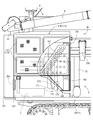
- a traveling machine body 1 supported by a pair of left and right crawler belts 2 includes a machine body frame 150 formed by connecting a plurality of frames in a substantially lattice shape in plan view.
- a step frame 151 formed by combining box frames is provided on one side of the front portion of the body frame 150.
- a pair of girder frames 152 on the right side of the machine body frame 150 extend forward, and step frames 151 are erected on the forward projecting portions of these girder frames 152.
- the cab 5 is disposed on the step frame 151.
- a box-shaped engine room frame 153 is erected on one side of the rear part of the threshing device 9 in the traveling machine body 1, that is, on the right side of the rear part of the machine body frame 150 (behind the step frame 151).
- the engine 7 is supported in an anti-vibration manner inside the engine room frame 153.
- the lower end side of the rear left vertical frame constituting the engine room frame 153 is fixed to the upper surface side of the rear support 272 fastened to the mounting base 275 at the rear of the body frame 150.
- the rear support 272 also functions as a component of the engine room frame 153.
- the hydraulic pump case 66 is positioned between the threshing device 9 and the engine 7 in the traveling machine body 1 (airframe frame 150).
- the step frame 151 and the engine room frame 153 support the right side wall of the threshing device 9 so that it cannot swing laterally.
- the left corner portion of the step frame 151 is connected to the right wall of the threshing device 9 via the connection plate 154.
- a front right corner portion of the engine room frame 153 is connected to the right wall of the threshing device 9 via a support arm 155.
- the middle part of the upper right beam frame in the engine room frame 153 is connected to the right wall of the threshing device 9 via the connection block 156.
- the lower end side of the Glen tank 6 is formed in a constricted shape by left and right inclined plates 6a and 6b.
- a bottom feed conveyor 60 having a longitudinal direction is disposed at the bottom of the narrowed portion in the Glen tank 6.
- the rear end side of the bottom feed conveyor protrudes rearward from the rear surface of the Glen tank 6 and is accommodated in a transfer case 157 provided at the lower rear surface of the Glen tank 6.
- the bottom feed conveyor shaft 103 passes through the rear surface side of the transfer case 157.
- a grain discharge pulley 287 is provided on the rear projecting end side of the bottom feed conveyor shaft 103.
- the transfer case 154 is connected in communication with the lower end side of the vertical feed conveyor 61 provided on the rear surface side of the Glen tank 6.
- a front-rear longitudinal casing 158 is provided above the bottom feed conveyor 60. The presence of the casing 158 prevents the grain itself in the Glen tank 6 from compacting the bottom feed conveyor 60 and hindering the grain conveyance.
- the Glen tank 6 is viewed from below by a step frame 151 on one side of the front part of the body frame 150 and an engine room frame 153 on one side of the rear part of the body frame 150. It is supported.
- the mounting bracket 161 to which the lower end portion of the Glen tank 6 is placed and fixed on the rear upper horizontal frame of the step frame 151 and the central portion of the front upper horizontal frame and the rear upper horizontal frame in the engine room frame 153. 163 is provided.
- These mounting brackets 161 to 163 are arranged in a line so as to correspond to the front and rear lower ends of the Glen tank 6.
- the lower end front portion of the Glen tank 6 is bolted to the mounting bracket 161 on the step frame 151 side.
- the front half mounting bracket 162 of the engine room frame 153 is bolted to the middle portion of the lower end of the Glen tank 6.
- a joint case 157 provided on the rear surface side of the Glen tank 6 is bolted to the rear mounting bracket 163 of the engine room frame 153.
- the left inclined plate 6a side which is a part of the Glen tank 6, overlaps the threshing device 9 so as to be covered from above.
- the left and right side surfaces of the Glen tank 6 are positioned above the corresponding track frames 50 respectively.
- the lateral width of the Glen tank 6 is within the lateral width of the body frame 150. Therefore, both the Glen tank 6 and the threshing device 9 are within the left and right widths of the body frame 150.
- a vertically long groining conveyor 32 that conveys the first thing collected in the first conveyor mechanism 30 to the Glen tank 6. Is supported upright.
- the whipping conveyor 32 penetrates the left inclined plate 6a of the Glen tank 6 upward from below.
- a midway portion of the cereal conveyor 32 is connected to the left inclined plate 6 a of the Glen tank 6 via a fixed plate 164.
- the penetration portion of the whipping conveyor 32 is blocked by a fixed plate 164. Therefore, like the step frame 151 and the engine room frame 153, the cereal conveyor 32 also functions as a strength member that supports the Glen tank 6 from below.
- the auxiliary grain raising conveyor 165 is mounted
- the upper end side of the auxiliary mashing conveyor 165 protrudes upward from the upper surface opening of the glen tank 6.
- the presence of the auxiliary cereal conveyor 165 ensures the height of cerealing during the harvesting operation, and the grains are dispersed and discharged into the glen tank 6. The total height during normal combine transport can be lowered by removing the auxiliary cereal conveyor 165.
- an engine room frame 153 surrounding the engine 7 is provided on one side of the rear part of the threshing device 9 in the traveling machine body 1.
- the Glen tank 6 is supported from below by a step frame 151 that supports a certain operating unit 5 and the engine room frame 153, and a part of the Glen tank 6 is overlapped above the threshing device 9.
- the said threshing device 9 and the grain tank 6 can be arranged good left-right balance. For this reason, the balance of the center of gravity of the entire ordinary combine is improved (lowering the center of gravity can be achieved), and the running stability can be improved. In addition, since the right and left weight balance of the traveling machine body 1 is stabilized, there is an advantage that it is possible to suppress the shake of the traveling machine body 1 in the lateral width direction.
- a whipping conveyor 32 that conveys the first thing from the threshing device 9 to the Glen tank 6 is provided, and the cereal conveyor 32 is placed in the Glen tank 6. Since the grain tank 6 and the cereal conveyor 32 are connected by penetrating upward from below, the cereal conveyor 32 functions as a strength member that supports the grain tank 6 from below. Therefore, the Glen tank 6 can be stably supported by the step frame 151, the engine room frame 153, and the cereal conveyor 32. Moreover, since the cereal conveyor 32 penetrates the grain tank 6, the presence of the cereal conveyor 32 causes the lateral vibration of the grain tank 6 in the lateral direction, and thus the left and right sides of the traveling machine body 1. The runout in the width direction can be further reduced.
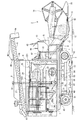
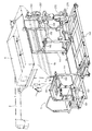
- the cooling air passage structure of the engine 7 will be described with reference to FIGS. 19 and 21 to 23.
- the engine 7 is supported in an anti-vibration manner on the inner side of the engine room frame 153 erected on the right side of the rear portion of the body frame 150.
- the output shaft 67 of the engine 7 projects from both front and rear side surfaces of the engine 7.
- An engine output pulley 283 is pivotally supported on the rearward projecting portion of the output shaft 67.
- a cooling fan 170 is provided at the front projecting portion of the output shaft 67.
- a radiator 172 for cooling the engine water is disposed via a fan shroud 171.
- the cover duct body 173 functions as a cooling air path for the engine 7.
- the outside air is taken in by the cooling fan 170 through the cover duct body 173 (cooling air passage) and the radiator 172, whereby the radiator 172, the engine 7 and the hydraulic pump case 66 located on the side of the radiator 172 are air-cooled. Will be.
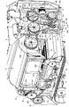
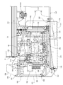
- the cover duct body 173 includes a hollow housing side duct 174 located on the right side of the engine 7 and a hollow housing front duct 175 located in front of the radiator 172 and the cooling fan 171. It is configured in a letter shape.
- the cover duct body 173 (the side duct 174 and the front duct 175) is connected and supported by an engine room frame 153 surrounding the engine 7. As shown in FIG. 22, the height position of the side duct 174 is set to be higher than the height position of the front duct 175.
- a plurality of outside air intakes 176 (four in the embodiment) are formed on the right side surface on the outer side of the side duct 174. Each outside air intake 176 is provided with a dustproof filter 177.
- the rear side of the front duct 175 is open.
- a radiator 172 faces the opening.
- the left front part of the side duct 174 and the right part of the front duct 175 communicate with each other.
- the side portion is taken in from the outside air intake port 176 to the lower side of the front portion of the side duct 174.
- An inclined guide portion 178 that is inclined forward and downward is formed so as to guide the cooling air flowing in the lower side of the duct 175 to the bottom surface side of the front duct 175.
- an inclined guide portion 179 inclined obliquely downward to the left so as to guide the cooling air flowing through the upper side in the side duct 175 to the front duct 175.
- the inclined guide portion 179 on the front duct 175 extends along the right inclined plate 6 b of the Glen tank 6.
- the presence of both the inclined guide portions 178 and 179 makes the side duct 174 and the front duct 175 different from each other even though the height position of the side duct 174 and the height position of the front duct 175 are different.
- the communication port 180 can be made large in the vertical direction, and the cooling air taken in from the outside air intake port 176 can be smoothly sent from the side duct 174 to the front duct 175.
- a shield plate 181 with a punch hole that restricts the intake of cooling air from the two outside air intakes 176 on the front side of the right side surface of the side duct 174 is above the inclined guide portion 178 in the side duct 174. Is arranged.
- the shielding plate 181 When the shielding plate 181 is disposed at the location, the suction pressure of the cooling air from the two front outside air intakes 176 is suppressed, and as much cooling air as possible is taken in from all the 4 outside air intake ports 176, A sufficient amount of cooling air can be secured while suppressing the wind speed.
- the side duct 174 is an opening 182 exposing the lower right side of the engine 7.
- the opening 182 is covered with a detachable side cover 183. Therefore, if the side cover 183 is removed, the lower right side of the engine 7 can be exposed, and maintenance work such as cleaning and maintenance of the engine 7 and the like can be easily performed.
- the upper side of the engine 7 is covered with the Glen tank 6 as can be seen from the shape relationship between the inclined guide portion 179 on the front duct 175 and the right inclined plate 6b of the Glen tank 6. Needless to say, the left side of the engine 7 and the hydraulic pump case 66 is covered with the threshing device 9.
- the center back cover 185 is configured to be horizontally openable and closable via a hinge 189 provided on a center support bar 188 on the rear side of the engine room frame 153.
- the left back cover 186 is configured to be horizontally openable and closable via a hinge 191 provided on the left support bar 190 on the rear side of the engine room frame 153.
- the right rear cover 187 is fixed to the right support bar 192 on the rear side of the engine room frame 153.
- the center and left rear covers 185 and 186 are provided with a plurality of filter-equipped outdoor air outlets 193 and 194, respectively. Warm air after being blown to the radiator 172, the engine 7, and the hydraulic pump case 66 is discharged from the lower part of the body frame 150 and from the outside air outlets 193 and 194 of the center and left rear cover 186.
- a traveling combine 1 equipped with the engine 7 as a power source, a mowing device 3 having a cutting blade 15, and a threshing device 9 having a handling cylinder 21,
- the engine 7 is disposed on one side of the rear portion of the threshing device 9 in the traveling machine body 1.
- the engine water cooling radiator 172 and the engine 7 and the radiator 172 air cooling cooling fan are disposed in front of the engine 7. 170, while the engine 7 is covered by a cover duct body 173 that covers a region from the other side opposite to the threshing device 9 in the engine 7 to the front of the radiator 172 and the cooling fan 170.
- the cooling air passage is formed, the other side portion of the cover duct body 173 that is parallel to the output shaft 67 of the engine 7 is formed. , It is possible to form a wide outside-air inlet 176 opening area. For this reason, it is possible to suppress the suction pressure while ensuring a sufficient amount of cooling air to be taken into the cooling air passage, and to reduce adhesion of dust and the like accompanying the intake of the cooling air. In addition, a complicated structure that removes dust by switching the direction of the blades of the cooling fan 170 is not necessary, which can contribute to cost reduction.
- the cover duct body 173 includes a side duct 174 located on the other side of the engine 7, and a front duct 175 located in front of the radiator 172 and the cooling fan 170. Since the height position of the duct 174 is set higher than the height position of the front duct 175 and the outside air intake port 176 is formed on the side surface of the side duct 174 on the outer side, the side duct 174 It is highly effective in preventing dust and other dust from adhering to the height position away from the field.
- the lower side of the side duct 174 is formed in an opening 182 that exposes the lower part on the other side of the engine 7, and the opening 182 is covered with a removable side cover 183.
- the opening 182 formed by the difference in position is effectively used to expose the lower part of the other side of the engine 7 by removing the side cover 183 so that maintenance work such as cleaning and maintenance of the engine 7 and the like can be easily performed. There is also an advantage that can be done.
- the hydraulic pump case 66 since the hydraulic pump case 66 is disposed between the threshing device 9 and the engine 7 in the traveling machine body 1, the hydraulic pump case 66 is also cooled by the cooling air to the engine 7. it can. Since a cooling structure dedicated to the hydraulic pump case 66 is unnecessary, it is possible to contribute to cost reduction while maintaining stable driving of the hydraulic system.
Landscapes
- Life Sciences & Earth Sciences (AREA)
- Environmental Sciences (AREA)
- Combines (AREA)
- Harvester Elements (AREA)
Abstract
Priority Applications (1)
| Application Number | Priority Date | Filing Date | Title |
|---|---|---|---|
| CN201180067497.3A CN103369954B (zh) | 2011-02-15 | 2011-12-08 | 普通型联合收割机 |
Applications Claiming Priority (2)
| Application Number | Priority Date | Filing Date | Title |
|---|---|---|---|
| JP2011-029939 | 2011-02-15 | ||
| JP2011029939A JP5828581B2 (ja) | 2011-02-15 | 2011-02-15 | 普通型コンバイン |
Publications (1)
| Publication Number | Publication Date |
|---|---|
| WO2012111219A1 true WO2012111219A1 (fr) | 2012-08-23 |
Family
ID=46672169
Family Applications (1)
| Application Number | Title | Priority Date | Filing Date |
|---|---|---|---|
| PCT/JP2011/078388 Ceased WO2012111219A1 (fr) | 2011-02-15 | 2011-12-08 | Moissonneuse-batteuse conventionnelle |
Country Status (3)
| Country | Link |
|---|---|
| JP (1) | JP5828581B2 (fr) |
| CN (1) | CN103369954B (fr) |
| WO (1) | WO2012111219A1 (fr) |
Cited By (1)
| Publication number | Priority date | Publication date | Assignee | Title |
|---|---|---|---|---|
| US10827682B2 (en) | 2018-10-02 | 2020-11-10 | Deere & Company | Independent air controlled sieve |
Families Citing this family (8)
| Publication number | Priority date | Publication date | Assignee | Title |
|---|---|---|---|---|
| JP2014158454A (ja) * | 2013-02-20 | 2014-09-04 | Yanmar Co Ltd | コンバイン |
| JP2014176342A (ja) * | 2013-03-14 | 2014-09-25 | Yanmar Co Ltd | コンバイン |
| KR20150137955A (ko) * | 2014-05-29 | 2015-12-09 | 이세키노우키가부시키가이샤 | 콤바인 |
| JP6242308B2 (ja) * | 2014-08-05 | 2017-12-06 | 株式会社クボタ | 自脱型コンバイン |
| JP6594812B2 (ja) * | 2016-03-23 | 2019-10-23 | ヤンマー株式会社 | コンバイン |
| JP6689126B2 (ja) * | 2016-04-26 | 2020-04-28 | ヤンマー株式会社 | 作業車両制御システム |
| JP6983516B2 (ja) * | 2016-04-28 | 2021-12-17 | 株式会社クボタ | 作業車 |
| JP7085981B2 (ja) * | 2018-12-27 | 2022-06-17 | 株式会社クボタ | コンバイン |
Citations (5)
| Publication number | Priority date | Publication date | Assignee | Title |
|---|---|---|---|---|
| JP2003072391A (ja) * | 2001-09-06 | 2003-03-12 | Yanmar Agricult Equip Co Ltd | 農作業機 |
| JP2005199816A (ja) * | 2004-01-14 | 2005-07-28 | Kubota Corp | 収穫機 |
| JP2007056761A (ja) * | 2005-08-24 | 2007-03-08 | Yanmar Co Ltd | エンジンの冷却装置 |
| JP2007175059A (ja) * | 2007-02-20 | 2007-07-12 | Kubota Corp | エンジン冷却装置付き収穫機 |
| JP2009268367A (ja) * | 2008-04-30 | 2009-11-19 | Kubota Corp | 作業車両 |
-
2011
- 2011-02-15 JP JP2011029939A patent/JP5828581B2/ja not_active Expired - Fee Related
- 2011-12-08 WO PCT/JP2011/078388 patent/WO2012111219A1/fr not_active Ceased
- 2011-12-08 CN CN201180067497.3A patent/CN103369954B/zh not_active Expired - Fee Related
Patent Citations (5)
| Publication number | Priority date | Publication date | Assignee | Title |
|---|---|---|---|---|
| JP2003072391A (ja) * | 2001-09-06 | 2003-03-12 | Yanmar Agricult Equip Co Ltd | 農作業機 |
| JP2005199816A (ja) * | 2004-01-14 | 2005-07-28 | Kubota Corp | 収穫機 |
| JP2007056761A (ja) * | 2005-08-24 | 2007-03-08 | Yanmar Co Ltd | エンジンの冷却装置 |
| JP2007175059A (ja) * | 2007-02-20 | 2007-07-12 | Kubota Corp | エンジン冷却装置付き収穫機 |
| JP2009268367A (ja) * | 2008-04-30 | 2009-11-19 | Kubota Corp | 作業車両 |
Cited By (1)
| Publication number | Priority date | Publication date | Assignee | Title |
|---|---|---|---|---|
| US10827682B2 (en) | 2018-10-02 | 2020-11-10 | Deere & Company | Independent air controlled sieve |
Also Published As
| Publication number | Publication date |
|---|---|
| CN103369954A (zh) | 2013-10-23 |
| JP2012165702A (ja) | 2012-09-06 |
| CN103369954B (zh) | 2016-01-20 |
| JP5828581B2 (ja) | 2015-12-09 |
Similar Documents
| Publication | Publication Date | Title |
|---|---|---|
| JP5828581B2 (ja) | 普通型コンバイン | |
| JP5825712B2 (ja) | コンバイン | |
| JP5797980B2 (ja) | コンバイン | |
| JP2011250751A (ja) | 普通型コンバイン | |
| WO2012111233A1 (fr) | Moissonneuse de type classique | |
| JP2012165662A (ja) | 普通型コンバイン | |
| WO2012077370A1 (fr) | Moissonneuse-batteuse classique | |
| JP5779013B2 (ja) | 普通型コンバイン | |
| JP2014064519A (ja) | コンバイン | |
| WO2012108459A1 (fr) | Moissonneuse de type classique | |
| JP5837760B2 (ja) | コンバイン | |
| JP5702679B2 (ja) | 普通型コンバイン | |
| JP5788169B2 (ja) | 作業車両 | |
| JP5808113B2 (ja) | 普通型コンバイン | |
| JP2013059279A (ja) | コンバイン | |
| WO2012077496A1 (fr) | Moissonneuse-batteuse | |
| JP2011250750A (ja) | 普通型コンバイン | |
| JP5764047B2 (ja) | コンバイン | |
| WO2017221842A1 (fr) | Moissonneuse-batteuse | |
| JP5780628B2 (ja) | 普通型コンバイン | |
| JP2015146755A (ja) | コンバイン | |
| JP2011250752A (ja) | 普通型コンバイン | |
| JP2011182744A (ja) | コンバイン | |
| JP2017158504A (ja) | コンバイン | |
| JP6487356B2 (ja) | コンバイン |
Legal Events
| Date | Code | Title | Description |
|---|---|---|---|
| WWE | Wipo information: entry into national phase |
Ref document number: 201180067497.3 Country of ref document: CN |
|
| 121 | Ep: the epo has been informed by wipo that ep was designated in this application |
Ref document number: 11858999 Country of ref document: EP Kind code of ref document: A1 |
|
| WWE | Wipo information: entry into national phase |
Ref document number: 1301004474 Country of ref document: TH |
|
| NENP | Non-entry into the national phase |
Ref country code: DE |
|
| 122 | Ep: pct application non-entry in european phase |
Ref document number: 11858999 Country of ref document: EP Kind code of ref document: A1 |